1
~
... ~
0·······.
..q
If,··· D····~ \.
OPERATORS MANUAL
7.6KW ETO 60HZ
5.7KW ETO 50HZ
MARINE 01 EL GENERATORS
SECOND EDITION
DECEMBER 2007
~
WESTERBEKE
WESTERBEKE CORPORATION -150 JOHN HANCOCK ROAD
MYLES STANDISH INDUSTRIAL PARK - TAUNTON MA 02780
WEBSITE: WWW.WESTERBEKE.COM
----
!\IMM4 Member National Marine Manufacturers Association
~~.,.,
CALIFORNIA
PROPOSITION 65 WARNING
Marine diesel and gasoline engine
exhaust and some of its constituents
are known to the State of California
to cause cancer, birth defects,
and other reproductive harm.
A WARNING
Exhaust gasses contain Carbon Monoxide, an odorless and
colorless gas. Carbon Monoxide is poisonous and can cause
unconsciousness and death. Symptoms of Carbon Monoxide
exposure can include:
- Throbbing in Temples
- Dizziness
-Nausea
- Muscular Twitching
-Headache
- Vomiting
- Weakness and Sleepiness - Inability to Think Coherently
IF YOU OR ANYONE ELSE EXPERIENCE ANY OF THESE SYMPTOMS,
GET OUT INTO THE FRESH AIR IMMEDIATELY. If symptoms persist,
seek medical attention. Shut down the unit and do not restart
until it has been inspected and repaired.
WARNING
Generators Produce CARBON MONOXIDE.
Regular Maintenance Required
lFJy~::!~:,:!
A WARNING DECAL is provided by WESTERBEKE and
should be fixed to a bulkhead near your engine or
generator.
WESTERBEKE also recommends installing CARBON
MONOXIDE DETECTORS near the engine room. They
are inexpensive and easily obtainable at your local
hardware store.
Engines & Generators
SAFETY INSTRUCTIONS
PREVENT BURNS - FIRE
INTRODUCTION
Read this safety manual carefully. Most accidents are
caused by failure to follow fundamental rules and
precautions. Know when dangerous conditions exist and
take the necessary precautions to protect yourself, your
personnel, and your machinery.
The following safety instructions are in compliance with
the American Boat and Yacht Council (ABYC) standards.
•
Prevent flash fires. Do not smoke or permit flames or
sparks to occur near the carburetor, fuel line, filter, fuel
pump, or other potential sources of spilled fuel or fuel
vapors. Use a suitable container to catch all fuel when
removing the fuel line, carburetor, or fuel filters.
PREVENT ELECTRIC SHOCK
•
Do not operate with a Coast Guard Approved flame
arrester removed. Backfire can cause severe injury or
death.
•
Do not operate with the air cleaner/silencer removed.
Backfire can cause severe injury or death.
•
Do not smoke or permit flames or sparks to occur near
the fuel system. Keep the compartment and the
engine/generator clean and free of debris to minimize the
chances of fire. Wipe up all spilled fuel and engine oil.
Be aware -
A WARNING: Do not touch AC electrical connections
while engine is running, or when connected to shore
power. Lethal voltage is present at these connections!
A WARNING: Fire can cause injury or death!
•
Do not operate this machinery without electrical
enclosures and covers in place.
•
Shut off electrical power before accessing electrical
equipment.
•
•
Use insulated mats whenever working on electrical
equipment.
PREVENT BURNS - EXPLOSION
•
Make sure your clothing and skin are dry, not damp
(particularly shoes) when handling electrical equipment.
•
Remove wristwatch and all jewelry when working on
electrical equipment.
•
Do not connect utility shore power to vessels AC
circuits, except through a ship-to-shore double throw
transfer switch. Damage to vessels AC generator may
result if this procedure is not followed.
•
Electrical shock results from handling a charged capacitor. Discharge capacitor by shorting terminals together.
A WARNING: Explosions from fuel vapors can cause
injury or death!
•
Follow re-fueling safety instructions. Keep the vessels
hatches closed when fueling. Open and ventilate cabin
after fueling. Check below for fumes/vapor before
running the blower. Run the blower for four minutes
before starting your engine.
•
All fuel vapors are highly explosive. Use extreme care
when handling and storing fuels. Store fuel in a wellventilated area away from spark-producing equipment
and out of the reach of children.
•
Do not fill the fuel tank(s) while the engine is running.
•
Shut off the fuel service valve at the engine when servicing
the fuel system. Take care in catching any fuel that might
spill. DO NOT allow any smoking, open flames, or other
sources of fire near the fuel system or engine when servicing. Ensure proper ventilation exists when servicing the
fuel system.
•
•
•
Do not alter or modify the fuel system.
Be sure all fuel supplies have a positive shutoff valve.
Be certain fuel line fittings are adequately tightened and
free of leaks.
•
Make sure a fire extinguisher is installed nearby and is
properly maintained. Be familiar with its proper use.
Extinguishers rated ABC by the NFPA are appropriate
for all applications encountered in this environment.
PREVENT BURNS - HOT ENGINE
A WARNING: Do not touch hot engine parts or
exhaust system components. A running engine gets
very hot!
•
Always check the engine coolant level at the coolant
recovery tank.
A WARNING: Steam can cause injury or death!
•
In case of an engine overheat, allow the engine to cool
before touching the engine or checking the coolant.
diesel fuel will bum.
Engines & Generators
SAFETY INSTRUCTIONS
ACCIDENTAL STARTING
TOXIC EXHAUST GASES
A WARNING: Accidental starting can cause injury
A WARNING: Carbon monoxide (CO) is a deadly gas!
or death!
•
Make certain all personnel are clear of the engine before
starting.
Ensure that the exhaust system is adequate to expel gases
discharged from the engine. Check the exhaust system
regularly for leaks and make sure the exhaust
manifolds/water-injected elbow is securely attached.
•
Make certain all covers, guards, and hatches are
re-installed before starting the engine.
Be sure the unit and its surroundings are well ventilated.
Run blowers when running the generator set or engine.
•
Do not run the generator set or engine unless the boat is
equipped with a functioning marine carbon monoxide
detector that complies with ABYCA-24. Consult your
boat builder or dealer for installation of approved
detectors.
•
For additional information refer to ABYC T-22
(educational information on Carbon Monoxide).
•
Disconnect the battery cables before servicing the engine/
generator. Remove the negative lead first and reconnect
it last.
•
•
BATTERY EXPLOSION
A WARNING: Battery explosion can cause injury
or death!
•
•
Do not smoke or allow an open flame near the battery
being serviced. Lead acid batteries emit hydrogen, a
highly explosive gas, which can be ignited by electrical
arcing or by lit tobacco products. Shut off all electrical
equipment in the vicinity to prevent electrical arcing
during servicing.
A WARNING: Carbon monoxide (CO) is an invisible
odorless gas. Inhalation produces flu-like symptoms,
nausea or death!
Never connect the negative (-) battery cable to the
positive (+) connection terminal of the starter solenoid.
Do not test the battery condition by shorting the terminals
together. Sparks could ignite battery gases or fuel vapors.
Ventilate any compartment containing batteries to prevent
accumulation of explosive gases. To avoid sparks, do not
disturb the battery charger connections while the battery
is being charged.
•
Avoid contacting the terminals with tools, etc., to prevent
bums or sparks that could cause an explosion. Remove
wristwatch, rings, and any other jewelry before handling
the battery.
•
Always tum the battery charger off before disconnecting
the battery connections. Remove the negative lead first
and reconnect it last when disconnecting the battery.
•
Do not use copper tUbing in diesel exhaust systems. Diesel
fumes can rapidly destroy copper tUbing in exhaust
systems. Exhaust sulfur causes rapid deterioration of
copper tubing resulting in exhaust/water leakage.
•
Do not install exhaust outlet where exhaust can be drawn
through portholes, vents, or air conditioners. If the engine
exhaust discharge outlet is near the waterline, water could
enter the exhaust discharge outlet and close or restrict the
flow of exhaust. Avoid overloading the craft.
•
Although diesel engine exhaust gases are not as toxic as
exhaust fumes from gasoline engines, carbon monoxide
gas is present in diesel exhaust fumes. Some of the
symptoms or signs of carbon monoxide inhalation or
poisoning are:
BATTERY ACID
A WARNING: Sulfuric acid in batteries can cause
Inability to think coherently
Throbbing in temples
Muscular twitching
Nausea
Weakness and sleepiness
AVOID MOVING PARTS
severe injury or death!
•
Vomiting
Dizziness
Headache
A WARNING: Rotating parts can cause injury
When servicing the battery or checking the electrolyte
level, wear rubber gloves, a rubber apron, and eye
protection. Batteries contain sulfuric acid which is
destructive. If it comes in contact with your skin, wash it
off at once with water. Acid may splash on the skin or
into the eyes inadvertently when removing electrolyte
caps.
or death!
•
..
Do not service the engine while it is running. If a
situation arises in which it is absolutely necessary to
make operating adjustments, use extreme care to avoid
touching moving parts and hot exhaust system
components.
Engines & Generators
II
SAFETY INSTRUCTIONS
•
•
ABYC, NFPA AND USCG PUBLICATIONS FOR
INSTALLING DIESEL ENGINES
Do not wear loose clothing or jewelry when servicing
equipment; tie back long hair and avoid wearing loose
jackets, shirts, sleeves, rings, necklaces or bracelets that
could be caught in moving parts.
Read the following ABYC, NFPA and USCG publications
for safety codes and standards. Follow their
recommendations when installing your engine.
Make sure all attaching hardware is properly tightened.
Keep protective shields and guards in their respective
places at all times.
•
Do not check fluid levels or the drive belts tension while
the engine is operating.
•
Stay clear of the drive shaft and the transmission coupling
when the engine is running; hair and clothing can easily
be caught in these rotating parts.
ABYC (American Boat and Yacht Council)
"Safety Standards for Small Craft"
Order from:
ABYC
3069 Solomon's Island Rd.
Edgewater, MD 21037
NFPA (National Fire Protection Association)
"Fire Protection Standard for Motor Craft"
Order from:
HAZARDOUS NOISE
A WARNING: High noise levels can cause hearing
NFPA
11 Tracy Drive
Avon Industrial Park
Avon, MA 02322
loss!
•
Never operate an engine without its muffler installed.
•
Do not run an engine with the air intake (silencer)
removed.
•
Do not run engines for long periods with their enclosures
open.
USCG (United States Coast Guard)
"USCG 33CFR183"
Order from:
U.S. Government Printing Office
Washington, D.C. 20404
A WARNING: 00 not work on machinery when you are
mentally or physically incapaCitated by fatigue!
OPERATORS MANUAL
Many of the preceding safety tips and warnings are repeated
in your Operators Manual along with other cautions and
notes to highlight critical information. Read your manual
carefully, maintain your equipment, and follow all safety
procedures.
GASOLINE ENGINE AND GENERATOR INSTALLATIONS
Preparations to install an engine should begin with a
thorough examination of the American Boat and Yacht
Council's (ABYC) standards. These standards are a
combination of sources including the USCG and the NFPA.
Sections of the ABYC standards of particular interest are:
H-2 Ventilation
P-l Exhaust Systems
P-4 Inboard Engines
E-9 DC Electrical Systems
All installations must comply with the Federal Code of
Regulations (FCR).
Engines & Generators
...
III
INSTALLATION
When installing WESTERBEKE engines and generators it is important that strict
attention be paid to the following information:
CODES AND REGULATIONS
Strict federal regulations, ABYC guidelines, and safety codes must be complied with
when installing engines and generators in a marine environment.
SIPHON-BREAK
For installations where the exhaust manifold/water injected exhaust elbow is close to
or will be below the vessel's waterline, provisions must be made to install a siphonbreak in the raw water supply hose to the exhaust elbow. This hose must be looped a
minimum of 20" above the vessel's waterline. Failure to use a siphon-break when
the exhaust manifold/water injected exhaust elbow is near or below the loaded
water line of the vessel will result in raw water damage to the engine and possible
flooding of the vessel.
If you have any doubt about the position of the water-injected exhaust elbow relative
to the vessel's waterline under the vessel's various operating conditions, install a
siphon-break.
NOTE: A siphon-break requires periodic inspection and cleaning to ensure proper
operation. Failure to properly maintain a siphon-break can result in catastrophic
engine damage. Consult the siphon-break manufacturer for proper maintenance.
EXHAUST SYSTEM
The exhaust hose must be certified for marine use. The system must be designed to
prevent water from entering the exhaust under any sea conditions and at any angle
A detailed 40 page Marine Installation Manual covering
gasoline and diesel, engines and generators, is supplied
with every unit.
Engines & Generators
iv
AVAILABLE FROM
YOUR WESTERBEKE
DEALER
TABLE OF CONTENTS
Engine Adjustments (cont.)
Parts Identification .............................................2
Introduction .........................................................3
Fuel, Engine Oil and Engine Coolant.. ............... .5
Preparations for Initial Start-Up .........................6
Digital Control Panel ...........................................7
Generator Break-In Procedure ............................9
Daily Routine .......................................................9
Maintenance Schedule (Chart) ......................... 10
Fuel System ....................................................... 12
Cooling System .................................................. 13
Generator Frequency ................................... 24
Electronic Governor .................................... 24
Valve Clearance Adjustment ....................... 25
Engine Compression .................................... 25
Spill Timing ....................................................... 26
Oil Pressure ................................................. 27
Glow Plugs .................................................. 27
Fuel Injectors ............................................... 28
Engine Troubleshooting (Chart) ........................29
Alternator Testing .............................................31
Fresh Water Cooling Circuit.. ..................... .14
Changing the Coolant.. ................................ 14
Air Intake ..................................................... 14
Thermostat ................................................... 15
Raw Water Intake Strainer .......................... 15
Raw Water Cooling System ........................ 16
Heat Exchanger ........................................... 16
Raw Water Pump ......................................... 16
Engine Lubricating Oil ....................................... 17
Engine Oil Change ...................................... 17
Remote Oil Filter (optional) ........................ 18
Starter Motor ..................................................... 19
Troubleshooting ........................................... 2,0
Battery Care ................................................. 33
Shore Power Connections .................................34
Generator Information .......................................35
7.6Kw Generator Single Phase .........................36
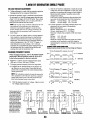
Circuit Breaker ............................................ 36
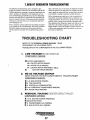
Troubleshooting .......................................... .37
No Load Voltage Adjustment ...................... 38
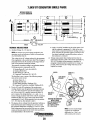
Residual Voltage Check ............................... 39
Bridge Rectifier .......................................... .40
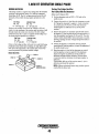
Exciter Rotor Field ..................................... .41
Measuring Resistance ...... ,.......................... .42
Voltage Connection Terminal ..................... .42
Lay-up and Recommissioning .......................... .43
Power Take-Off ..................................................45
Metric Conversion Data (Chart) ........................46
Suggested Spares ..............................................47
Generator Specifications ................................. .21
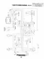
Wiring Diagram #52441.. ...................................22
Engine Adjustments ...........................................23
Drive Belt Adjustment ................................ 23
Torquing the Cylinder Head Bolts .............. 23
Engines & Generators
1
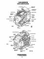
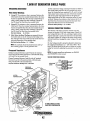
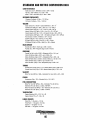
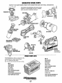
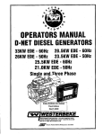
7.6KW GENERATOR
PARTS IDENTIFiCATION
"nlllll:""rlnll FOR
SIPHON BREAK
INJECTION
THERMOSTAT
ASSEMBLY
DRIVE BELT
COVER
Oil PRESSURE SENSOH--.?......
~--STARTER
ZINC
MOTOR
LEFT
SIDE
FRONT
HEAT
EXCHANGER
COOLANT PRESSURE CAP -.......""...
RAW WATER PUMP
AIR
REAR
MOUNTS
Engines & Generators
2
RIGHT SIDE
INTRODUCTION
This WESTERBEKE Diesel Generator is a product of
WESTERBEKE's long years of experience and advanced
technology. We take great pride in the superior durability and
dependable performance of our engines and generators.
Thank you for selecting WESTERBEKE.
In order to get the full use and benefit from your generator it
is important that you operate and maintain it correctly. This
manual is designed to help you do this. Please, read this'
manual carefully and observe all the safety precautions
throughout. Should your generator require servicing, contact
your nearest WESTERBEKE dealer for assistance.
This is your operators manual. A parts catalog is also
provided and a techmcal manual is available from your
WESTERBEKE dealer. If you are planning to install this
equipment contact your WESTERBEKE dealer for
WESTERBEKE'S installation manual.
PRODUCT SOFTWARE
Product software, (tech data, parts lists, manuals,
brochures and catalogs), provided from sources other than
WESTERBEKE are not within WESTERBEKE's control.
WESTERBEKE CANNOT BE RESPONSIBLE FOR THE
CONTENT OF SUCH SOFTWARE, MAKES NO
WARRANTIES OR REPRESENTATIONS WITH RESPECT
THERETO, INCLUDING ACCURACY, TIMEliNESS OR
COMPLETENESS THEREOF AND W/ILIN NO EVENT
BE UABLE FOR ANY TYPE OF DAMAGE OR INJURY
INCURRED IN CONNECTION WITH OR ARISING OUT
OF THE FURNISHING OR USE OF SUCH SOFTWARE.
WESTERBEKE customers should also keep in mind the
time span between printings ofWESTERBEKE product
software and the unavoidable existence of earlier
WESTERBEKE manuals. In summation, product software
provided with WESTERBEKE products, whether from
WESTERBEKE or other suppliers, must not and cannot
be relied upon exclusively as the definitive authority on
the respective product. It not only makes good sense
but is imperative that appropriate representatives of
WESTERBEKE or the supplier in question be consulted
to determine the accuracy and currentness of the
product software being consulted by the customer.
WARRANTY PROCEDURES
Your WESTERBEKE Warranty is included in a separate
folder. If, after 60 days of submittil;lg the Warranty Regiitry
form you have not received a customer identification card
registering your warranty, please contact the factory in
writing with model information, including the umt's serial
number and commission date.
Customer Identification Card
NOTES, CAUTIONS AND WARNINGS
As this manual takes you through the operating procedures,
maintenance schedules, and troubleshooting of your marine
engine, critical inforrr..ation will be .highlighted by NOTES,
CAUTIONS, and WARNINGS. An explanation follows:
, """,WESTERBEKE
I
Engines & Generators
Customer Identification
MR. GENERATOR OWNER
MAIN STREET
HOMETO'WN, USA
Model
Ser. #
Expires
NOTE: An operating procedure essential to note.
A
CAUTION: Procedures, which if not strictly
observed, can result in the damage Dr destruction of
your engine.
A
WARNING: Procedures, which if not properly
followed, can result in personal injury or loss of life.
Engines & Generators
3
INTRODUCTION
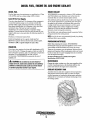
SERIAL NUMBER LOCATION
The engine and generator serial numbers and model numbers
are located on a decal on the generator housing. Take the
time to enter this infonnation on the illustration of the nameplate shown below, as this will provide a quick reference
when seeking technical information andlor ordering repair
parts.
..
..
----~----~--
NOTE: A carbon monoxide warning decal has been provided
by WESTERBEKE. AffIX this decal in a visible position in the
engine room.
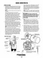
UNDERSTANDING THE DIESEL ENGINE
The diesel engine closely resembles the gasoline engine,
since the mechanism is essentially the same. The cylinders
are arranged above a closed crankcase;the crankshaft is of
the same general type as that of a gasoline engine, and the
diesel engine has the same type of valves, camshaft, pistons,
connecting rods and lubricating system.
Therefore, to a great extent, a diesel engine requires the
same preventive mainte)1ance as a gasoline engine. The
most in1portant factors are proper ventilation and proper
maintenance of the fuel, lubricating and cooling systems.
Replacement of fuel and lubricating filter elements at the
tin?e periods specified is a must, and frequent checking for
contamination (that is water, sediment, etc.) in the fuel sys-
tem is also essential. Another important factor is the use of
the same brand of high detergent diesel lubrication oil
designed specifically for diesel engines.
The diesel engine does differ from the gasoline engine,
however, in its method of handling and firing of fueL The
carburetor and ignition systems are replaced by a single
component - the fuel injection pump - which performs the
function of both.
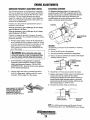
ORDERING PARTS
Whenever replacement parts are needed, always provide the
generator model number, engine serial number, and generator
serial number as they appear on the silver and black nameplate located on the generator end. You must provide us with
this information so we may properly identify your generator
set. In 'addition, include a complete part description and part
number for each part needed (see the separately furnished
Parts List). Insist upon WES1ERBEKE packaged parts
because will fo or generic parts are frequently not made to
the same specifications original equipment.
The engine serial number can also be found stamped into the
engine block just above the injection pump. The generator
serial number is stamped into the generator housing on the
fiat surface on the left side of the generator.
as
SPARES AND ACCESSORIES
Certain spares will be needed to support and maintain your
WESTERBEKE engine. Your local WESTERBEKE dealer
will assist you in preparing an inventory of spare parts.
See the SPARE PARTS page in this manual. For engine
accessories, see WESTERBEKE'S ACCESSORIES brochure.
An identification plate on the engine manifold also displays
the engine model and serial number.
INSTALLATION MANUAL
Publication #43400 provides detailed information for
installing generators and is available at your WES1ERBEKE
dealer.
Engines & Generators
4
DIESEL FUEL, ENGINE OIL AND ENGINE COOLANT
DIESEL FUEL
ENGINE COOLANT
Use fuel that meets the requirements or specification of Class
2-D (ASTM), and has a cetane rating of #45 or better.
WESTERBEKE recommends a mixture of 50% antifreeze
and 50% distilled water. Distilled water is free from the
chemicals that can corrode internal engine surfaces.
The antifreeze performs double duty. It allows the engine to
run at proper temperatures by transferring heat away from
the engine to the coolant, and lubricates and protects the
cooling circuit from rust and corrosion. Look for a good
quality antifreeze that contains Supplemental Cooling
Additives (SCAs) that keep the antifreeze chemically
balanced, crucial to long term protection.
The distilled water and antifreeze should be premixed before
being poured into the cooling circuit.
Care Of The Fuel Supply
Use only clean diesel fuel! The clearance of the components
in your fuel injection pump is very critical; invisible dirt
particles which might pass through the filter can damage
these finely finished parts. It is important to buy clean fuel,
and keep it clean. The best fuel can be rendered
unsatisfactory by careless handling or improper storage
facilities. To assure that the fuel going into the tank for your
engine's daily use is clean and pure, the following practice is
advisable:
Purchase a well-known brand of fuel.
Install and regularly service a good, visual-type fuel
filter/water separator between the fuel tank and the engine.
The Racor 120R is a good example of such a filter.
NOTE: Look for the new environmentallyJriendly long lasting
antifreeze that is now available.
PURCHASING ANTIFREEZE
Rather than preparing the mixture, WESTERBEKE
recommends buying the premixed antifreeze so that so that
when adding coolant the mixture will always be correct.
There are two common types of antifreeze, Ethylene Glycol
(green) and Propylene Glycol (red/purple), either can be used
but do not mix the two and if changing from one to another,
flush the engine thoroughly.
Premixed antifreeze for GASOLINE Engines:
Specification #ASTM 4656.
ENGINE OIL
Use a heavy duty engine oil with an API classification of CF,
CG-4, CH4 or CI-4. Change the engine oil after an initial 50
hours of break-in operation, and every 100 hours of operation
thereafter. For recommended oil use SAE 15W-40
(oil viscosity). WESTERBEKE recommends the use of
synthetic oil.
A
MAINTENANCE
CAUTION: Do not allow two or more brands of
Change the engine coolant every five years regardless of the
number of operating hours as the chemical additives that
protect and lubricate the engine have a limited life.
engi4e oil to mIx. Each brand contains its own additives;
additives of different brands could react in the mixture
to produce properlies harmful to your engine.
COOLANT RECOVERY TANK
A coolant recovery tank kit is supplied with each generator.
The purpose of this recovery tank is to allow for engine
coolant expansion and contraction during engine operation,
without the los!'; of coolant and without introducing air into
the cooling system.
Engines & Generators
5
PREPARATIONS FOR INITIAL START-UP
PRESTARTINSPECTION
A CAUTION: When starting the generator, it is
Before starting your generator set for the first time or after a
prolonged layoff, check the following items:
• Make certain the cooling water thru-hull petcock is open.
• Check the engine oil level: add oil to maintain the level at
the full mark on the dipstick.
• Check the fuel supply and examine the fuel filter/separator
bowls for contaminant's.
• Check the DC electrical system. Inspect wire connections
and battery cable connections. .
• Check load leads for correct connection as specified in the
wiring diagrams.
• Examine air inlet and outlet for air flow obstructions.
• Be sure no other generator or utility power is connected to
load lines.
• Be sure that in power systems with a neutral line that
•
recommended that al/ AC loads, especially large motors,
be switched OFF until the engine has come up to speed
and, in cold climates, starts to warm up. This precaution
will prevent damage caused by unanticipated operation
of the AC machinery and will prevent a cold engine from
stalling.
•
Check the coolant level in both the plastic recovery tank
and at the manifold.
NOTE: After the initial rwming of the generator, the air in
the engine's cooling system will be purged to the coolant
recovery tank. Open the air bleed petcock to ensure that
the neutral is properly grounded (or ungrounded) as the
the cooling system is purged oj air. After shutdown and
system requires, and that the generator neutral is properly
connected to the load neutral. In single phase systems an
incomplete or open neutral can supply the wrong line-toneutral voltage on unbalanced loads.
Visually examine the unit. Look for loose or missing
parts, disconnected wires, unattached hoses, and check
threaded connections. Search for any gasoline leaks.
after the engine IuJs cooled, the coolant from the recovery
tank will be drawn into the engine's cooling system to
replace the purged air.
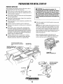
WAIT FOR THE ENGINE TO COOL
BEFORE REMOVING THE RADIATOR
CAP
FROM COOLANT
RECOVERY TANK
~~E~~oJ8::~~ur~RC:p,
TO LIfTOFF
STOP BOLT ADJUSTMENT
SPEED ADJUSTMENT
FACTORY SET
all DIPSTICK
Engines & Generators
6
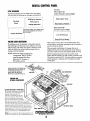
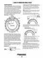
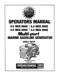
NOTE: DUling operation the color
of the LCD display may vary.
DIGITAL CONTROL PANEL®
Caused by heat, this is nomzal
no cause for concern.
CONTROL BOX
8 AMP FUSE
PROTECTS THE PANEL
ELECTRONICS FROM A
HIGH AMP LJVL,nLLlJ~U
UPARROW
SCROll LOCK
DOWN ARROW
INDICATOR LIGHTS - - l - - - - ; -
20 AMP DC CIRCUIT
BREAKER (ECU)
. START BUTTON
LIGHT
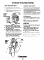
DESCRIPTION
WESTERBEKE'S Digital Control panel provides the
operator with an LCD display that continuously monitors
all the operations of the generator in easy to understand
text messages.
Battery Voltage
Oil Pressure
13.5 VI?C
40 PSI
o
30
o
100
SCROLL
SCROLL
START SEQUENCE
With the prestart inspection completed, Press the START
button and the automatic sequence will begin. The six
indicator lights will illuminate green and the panel will
display the following text:
Engine Hours
3.8 HOURS
Coolant Temperature
172F
o
300
SCROLL
"
Waiting for operator
Press start to
Engines & Generators
To stop the continuing sequence, press the SCROLL WCK
button. This enables the operator to monitor a single function
for any length of time. The word LOCK will appear in the
comer. use the up and down arrows to find and observe other
functions. To resume scrolling, press the SCROLL LOCK
button again.
engage generator
Pre Heating ......
7 Seconds
LpCK·
SCROLL LOCK
Cranking ..... .
Up and Down Arrows
When the display is in its cycling mode, the UP and DOWN
arrows can be used to adjust the dark and light contrast of the
screen.
RUN SEQUENCE
FUEL PRIMING
As the display cycles thru the engine functions, the speed
will come up to 1800 rpms-60Hz (1500 rprns-50Hz) and
the oil pressure and engine coolant will rise to their normal
readings. The functions will cycle in the following sequence:
I
I
l
Engine Speed
. Coolant Temperature
1800 RPM
172F
I
0
!
0
2500
SCROLL
I
!
Use the PRIME button on the digital control panel to purge
air and bring fuel back into the fuel lines after performing
fuel filter maintenance.
LCD DISPLAY
Periodically clean the control panel and its LCD screen using
a soft cloth.
I
300
NOTE: Operating temperatures may cause the LCD display to
vary in color. This is normal and a change in color will not
affect the operation of the control panel.
SCROLL
Engines & Generators
7
DIGITAL CONTROL PANEL
Examples:
Failure Light is red.
Goo/ant Temperature Light is orange.
STOP SEQUENCE
To stop the generator, press the STOP button. The display
will cycle thru the following text messages and shutdown.
High Engine Temp.
Waiting for operator
Shutting
Down
•
Press start to
Reset ECU to ReStart
engage generator
Failure Light is red.
Oil Pressure Light is orange.
THE CONTROL PANEL WILL POWER DOWN
AND IN A FEW MOMENTS THE DISPLAY
WILL GO BLANK
Engine Shutdown
I
Low Oil Pressure
Reset ECU to Restart
FAILURE LIGHT/SHUTDOWN
When a failure occurs, refer to the troubleshooting chart,
wiring diagram, and general operating text in this manual to
assist in solving the trouble_
There are many combinations of messages that can be
displayed but they are all self explanatory and the operator
can easily isolate and correct the problem should one occur.
Before restarting the generator, the 20 amp DC circuit
breaker must be pushed to the OFF position, and back to the
ON position to reset the BCU. Once the problem is corrected
and the generator is restarted, the LCD display will begin
cycling again._
If a problem occurs, the generator will shutdown and the
FAILURE light will illuminate red. In addition, one of the
indicator lights will change from green to orange to reveal
where the trouble has occurred and the display will text
message what has happened.
NOTE: When servicing/ changing DC
components. The DC power
must be turned off using
either the DC breaker or
the battery switch.
WHEN CHANGING THE GENERATORS
FREQUENCY (50/60 HZ) SWITCH #1
ON THE CONTROL PANEL ECU
BOARD MUST BE SWITCHED:
ON FOR 50 HZ AND OFF FOR 60 HZ.
CONTROL BOX
INTERNAL COMPONENTS
CAUTION (WESTERLINK or NMEA·2000):
The electronic components in the Digital
Diesels draw a very small amount of
amperage (milli-amps) from the
generator's starting battery when the
unit is in a static state. This maybe as
much as 50 milli-amps for the system
ECU and 50 milli-amps for each display.
This can be as much as 72 amp-hours in a I1wnths
time with no generator use. It is nat necessary to be
concerned with this slight amperage draw during IlOTIlIal
seasonal use. However, if the generator set is not to be
used for a number of months, such as winter storage, it is
best to disconnect the DC power to the generator with a
NMEA-2000 system or shut off the DC breaker on the
generator's control boxJor a WESTERUNK system.
NOTE: Keep in mind that the Westerbeke generator may -be
the DC power supply for the vessel's NMEA-2000 network.
8
GENERATOR BREAK-IN PROCEDURE
DESCRIPTION
Mter the first 10 hours of the generator's operation, the load
can be increased to the full-load rated output, then periodically vary the load.
Avoid overload at all times. An overload is signaled by smoky
exhaust with reduced output voltage and frequency. Monitor
the current being drawn from the generator and keep it within
the generator's rating. Since the generator operates at 1800
rpm to produce 60 hertz (or at 1500 rpm to produce 50
Hertz), control of the generator's break-in is govemed by the
current drawn from the generator.
Although your engine has experienced a minimum of one
hour of test operations at the factory to make sure accurate
assembly procedures were followed and that the engine
operated properly, a break-in time is required. The service
life of your engine is dependent upon how the engine is
operated and serviced during its initial hours of use.
Breaking-in a new engine basically involves seating the
piston,rings to the cylinder walls. Excessive oil consumption
and smoky operation indicate that the cylinder walls are
glazed or scored, which is caused by overloading the
engine during the break-in period.
Your new engine requires approximately 50 hours of initial
conditioning operation to break in each moving part in order
to maximize the perfolIDance and service life of the engine.
Perform this conditioning carefully, keeping in mind the
following:
Start the engine according to the STARTING PROCEDURE
section. Run the engine while checking that all systems (raw
water pump, oil pressure, battery charging) are functioning.
NOTE: Be aware of motor starting loads and the high current
draw required for starting motors. This starting amperage
draw can be 3 to 5 times normal rnnning amperage. See
GENERATOR INFORMATION in this manual.
GENERATOR ADJUSTMENTS
Once the generator has been placed in operation, there may be
governor adjustments required for engine speed (hertz) during
the engine's break-in period (first 50 hours) or after this
period see ENGINE SPEED (HERTZ) ADJUSTMENT) under
ENGINE ADJUSTMENTS.. A no-load voltage adjustment
may also be required in conjunction with the engine's speed
adjustment see GENERATOR INFORMATION.
AFTER START-UP
Once the generator has been started, check for proper operation and then encourage a fast warm-up. Run the generator
between 20% and 60% of full-load for the first 10 hours.
THE DAILY ROUTINE
CHECK LIST
NOTE: Some unstable rnnning may occur in a cold engine.
This condition should abate as normal operating temperature
is reached and loads are applied.
Follow this check list each day before starting your generator.
• Check that all generator circuit breakers (power panel) are
in the off position before starting.
A CAUTION: Do not operate the generator for iong
• Record the houlIDeter reading in your log (engine hours
relate to ,he maintenance schedule.)
periods oflime without a load being placed on the
generator.
Any' deficiency or problems in the following items must
be corrected before start up.
STOPPING THE GENERATOR
• Visually inspect the engine for fuel, oil, or water leaks.
Remove the AC loads from the generator one at a time.Allow
the generator to run for 3-5 minutes to stabilize the operating
temperature, then turn the key to the off position. Once the
generator is shutdown, close down all circuit breakers as a
safety precaution.
• Check the oil level (dipstick).
• Check the coolant level in the coolant recovery tank.
• Check your fuel supply.
• Check the starting batteries (weekly).
• Check drive belts for wear and proper tension (weekly).
CHECK WITH THE ENGINE RUNNING.
• Check for abnonnal noise such as knocking, vibrating and
blow-back sounds.
• Confirm exhaust smoke:
When the engine is cold - White Smoke.
When the engine is warm - almost Smokeless.
When the engine is overloaded some Black Smoke.
Engines & Generators
9
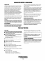
MAINTENANCE SCHEDULE
A WARNING: Never attempt to pedorm any service while the engine is
running. Wear the proper safety equipment such as goggles and gloves, and
use the correct tools for each job. /)isconnect the battery terminals when
servicing any of the engine's DC electrical equipment.
NOTE: Many of the following maintenance jobs are simple but others are more
difficult and may require the expert knowledge of a service mechanic.
SCHEDULED
MAINTENANCE
Fuel Supply
Fuel/Water Separator
Engine Oil Level
Coolant Level
Drive Belts
CHECK
EACH
DAY
HOURS OF OPERATION
50
100
250
500
750 1000 1250
Diesel No.2 rating of 45 cetane or higher.
0
0
Check for water and dirt in fuel (drain/replace filter
if necessary).
I 0
Oil level should indicate between MAX. and LOW on
dipstick.
0
Check at recovery tank; if empty, check at manifold.
Add coolant if needed.
0
Inspect for proper tension (3/8" to 112" deflection)
and adjust if needed. Check belt edges for wear.
weekly
Visual Inspection of Engine
0
/Fuel Filter & Inlet Filte
Starting Batteries
(and House Batteries)
EXPLANATION OF SCHEDULED
MAINTENANCE
NOTE: Please keep engine surface clean. Dirt
and oil will inhibit the engine's ability to
remain cool.
0
0
0
0
0
0
Check for fuel, oil and water leaks. Inspect wiring
and electrical connections. Keep bolts & nuts tight.
Check for loose belt tension.
Initial change at 50 hrs, then change every 250 hrs.
Every 50 operating hours check electrolyte levels
and make sure connections are very tight. Clean off
excessive corrosion.
0
weekly
Engine Oil (and filter)
0
0
0
0
0
0
0
Initial engine oil & filter change at 50 hrs., then
change both every 100 hours.
Generator
0
0
0
D
0
0
r:::J
Check that AC connections are clean and secure
with no chafing. See GENERATOR SECTION
for additional information.
Heat Exchanger Zinc Anode
0
0
D
0
0
0
0
Inspect zinc anode, rep late if needed, clear the heat
exchanger end of zinc anode debris.
0
0
0
[J
C
0
Change every 200 hours.
Fuel/Water Separator
Sea Water Pump
Remove pump and inspect impeller
drive shaft end for wear. Inspect drive
gear slot for wear. Repair/replace as
needed.
CI
0
~~-
Exhaust System
Engine Hoses
0
0
0
0
0
0
0
0
.---
0
Initial check at 50 hrs., then every 250 hrs. Inspect
for leaks. Check anti-siphon valve operation. Check
the exhaust elbow for carbon and/or corrosion
buildup on inside passages; clean and replace as
necessary. Check that all connections are tight.
0
Hose should be hard & tight. Replace if soft or
spongy. Check and tighten all hose clamps.
Engines & Generators
10
\
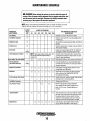
MAINTENANCE SCHEDULE
NOTE: Use the engine hour meter gauge to log your engine hours or record your
engine hours by running time.
SCHEDULED
MAINTENANCE
CHECK
EACH
DAY
HOURS OF OPERATION
50
Raw Water Pump
100 250 500
0
EXPLANATION OF SCHEDULED
750 1000 1250
MAINTENANCE
Remove the pump cover and inspect impeller, gas0
0
ket, cam and cover for wear. Check the bearings
and seals (the shaft can turn, but not wobble).
Lubricate when reassembling.
Coolant System
Electric Fuel Lift Pump
0
0
.
Fuel Filter
0
0
Alternator
0
0
Drain, flush, and refill cooling system with
appropriate antifreeze mixture compatible with
various cooling systern metals.
0
0
0
0
Periodically check the wiring connections and
inspect the fuel line connections.
0
0
0
0
Replace.
0
Check DC charge from alternator. Check the
mounting bracket; tighten electrical connections.
i
0
*Fuellnjectors
Check and adjust injection opening pressure and
spray condition (see ENGINE ADJUSTMENTS).
0
*Starter Motor
D
0
Check solenoid and motor for corrosion. Remove
and lubricate. Clean and lubricate the starter motor
pinion drive.
*Preheat Circuit
C
0
Check operation of preheat solenoid. Remove and
clean glow plugs; check resistance (4-6 ohms).
Reinstall with anti seize compound on threads.
*Engine Cylinder
Compression
0
0
Check compression pressure and timing
(see Engine Adjustments).
*Torque Cylinder Head
Hold-down bolts
0
D
0
At first 50 hours, then every 500 hours
(see ENGINE ADJUSTMENTS).
*Adjust the Valve Clearances
0
D
0
Adjllst Valve Clearances
(see ENGINE ADJUSTMENTS).
*Heat Exchanger
0
=
Remove, have professionally cleaned and
pressure tested.
NOTE: When servicing! changing DC components.
The DC power must be turned off using
"WESTERBEKE recommends this service be performed by an authorized mechanic.
either the DC breaker or the battery switch.
CAUTION (WESTERLINK or NMEA-2000): The electronic components in the Digital Diesels draw a very small amount of amperage (milU-amps) from the
generator's starting battery when the unit is in a static state. This maybe as much ds 50 milli-amps for the system ECU and 50 milli-amps for each display.
This can be as much as 72 amp-hours in a months time with no generator use. It is not necessary to be concerned with this slight amperage draw during
normal seasolUll use. However, if the generator set is not to be used for a number of months, such as winter storage, it is best to disconnect the DC power
to the generator with a NMEA-2000 system or shut off the DC breaker on the generator's control box for a WESTERLlNK system.
NOTE: Keep in mind that the Westerbeke generator may be
DC power supply for the vessel:y NMEA-2000 network.
Engines & Generators
11
FUEL SYSTEM
DIESEL FUEL
ENGINE FUEL FILTER
Use No.2 diesel fuel with a cetane rating of 45 or higher.
Do not use kerosene or home heating fuel.
Periodically check the fuel connections and the bowl for
leakage. Replace the filter element after the first 50 hours
then follow the MAINTENANCE SCHEDULE.
FUEL FILTERS
Changing/cleaning the filter element
The fuel injection pump and the fuel injectors are precisely
manufactured and they must receive clean diesel fuel, free
from water and dirt. To ensure this flow of clean fuel, the fuel
must pass through at least two fuel filters, a fuel water
separator and the engine's spin-on fuel filter. Visually inspect,
clean, and change these filters according to the maintenance
schedule in this manual.
1. Shut off the fuel supply.
2. Unscrew the retainer ring that holds the filter bowl to the
housing and allow the bowl to come away from the
housing,
3. Remove and replace the filter element and clean the bowl.
4. Replace the sealing "0" ring and reassemble the bowl
to the housing. Thread thc retainer ring on carefully
so as not to cross thread. When retainer contacts the
"0" ring, tighten 114 - 112 turns by hand. Open the fuel
supply and run the engine to inspect for leaks.
FUEL WATER SEPARATOR
A primary fuel filter of the water separating type must be
installed between the fuel tank and the engine to remove
water and other contaminants from the fuel before they can
be carried to the fuel system on the engine.
The owner/operator is responsible for making certain the
fuel reaching the engine's injection equipment is free of
impurities. This process is accomplished by installing and
maintaining a proper fuel filter/water separator between the
fuel tank and the generator/engine. Westerbeke recommends
a 10 micron filter be used.
FUEL INJECTION PUMP
The fuel injection pump is the most important component
of the diesel engine, requiring the utmost caution in handling.
The fuel injection pump has been thoroughly bench-tested
and the owner/operator is cautioned not to attempt to service
it. If it requires servicing, remove it and take it to an
authorized fuel injection pump service facility. Do not
attempt to disassembly and repair it.
·RING
LIGHTLY WIPE
WITH CLEAN FUEL
THE O-RING GASKET
ONLY NEEDS TO BE
REPLACES IF IT SHOWS
SIGNS OF AGING.
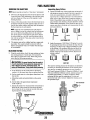
FUEL LIFT PUMP
Periodically check the fuel connections to and out of the pump
and make sure that no leakage is present and that the fittings
are tight and secure. The DC ground connection at one of the
pump's mounting bolts should be clean and well secured by
the mounting bolt to ensure proper pump operation.
When energized thru the preheat circuit, the fuel lift pump will
purge air from the fuel system and provide a continuous flow
of fuel as the engine is running.
FUEL
FILTER
INLET FUEL FILTER
To ensure clean fuel into the fuel lift pump, there is a small
in-line fuel filter connected to the fuel lift pump elbow.
Engines & Generators
12
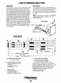
COOLING SYSTEM
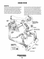
DESCRIPTION
fresh water coolant flows around the tubes; engine heat transferred to the fresh water coolant is conducted through the
tube walls to the raw water which is then pumped into the
exhaust system where finally it is discharged overboard. In
other words, the engine is cooled by fresh water coolant, this
coolant is cooled by raw water, and the raw water carries the
transferred heat overboard through the exhaust system. The
fresh water coolant and raw water circuits are independent of
each other. Using only fresh water coolant within the engine
allows the cooling water passages to stay clean and free from
harmful deposits.
Westerbeke marine diesel engines are designed and equipped
for fresh water cooling. Heat produced in the engine by combustion and friction is transferred to fresh water coolant
which circulates throughout the engine. This circulating fresh
water coolant cools the engine block, its internal moving
parts, and the engine oil. The heat is transferred externally
from the fresh water coolant to raw water by means of a heat
exchanger, similar in function to an automotive radiator. Raw
water flows through the tubes of the heat exchanger while
"-...~
---- ----- ---
--NOTE: KEEP PASSAGE
THROUGH THE MANIFOLD
CLEAR (A PIPE CLEANER
WORKS WELL).
EXHAUST
~ NOTE: AN ANTI-SIPHON
- ", VALVE MAY BE REQUIRED
\.
COOLING CIRCUIT
DIAGRAM (TYPICAL)
FRESH WATER
¢
RAWWATER.
Engines & Generators
13
COOLING SYSTEM
FRESH WATER COOLING CIRCUIT
CHANGING COOLANT
NOTE: Refer to the ENGINE COOLANT section for the recommended antifreeze and water mixture to be used as the
fresh water coolant.
The engine's coolant must be changed according to the
MAINTENANCE SCHEDULE. lfthe coolant is allowed to
become contaminated, it can lead to overheating problems.
Fresh water coolant is pumped through the engine by a
circulating pump, absorbing heat from the engine. The
coolant then passes through the thermostat into the manifold,
to the heat exchanger where it is cooled, and returned to the
engine block via the suction side of the circulating pump.
When the engine is staJ.1ed cold, external coolant flow is
prevented by the closed thermostat (although some coolant
flow is bypassed around the thermostat to prevent the exhaust
manifold from overheating). As the engine warms up, the
thennostat gradually opens, allowing full flow of the engine's
coolant to flow unrestricted to the external portion of the
cooling system.
A CAUTION: Proper cooling system maintenance is
critical; a substantial number of engine failures can be
traced back to cooling system corrosion.
Drain the engine coolant by removing the drain plug-on the
engine block and opening the manifold pressure cap. Flush
the system with fresh water, then reinstall the drain and start
the refill process.
NOTE: The drain petcock on the heat exchanger should also
be used to help drain engine coolant.
KEEP THE
TO COOLANT
RECOVERY TANK
COOLANT PASSAGE
CLEAR
COOLANT DRAIN
ALLEN HD PLUG 6MM
COOLANT EXPANSION
FROM COOLANT
RECOVERY TANK
PRESSURE
I I
/CAP
V-,j
OIL FILTER
Refilling the Coolant C'1
~
After replacing the engine block c'Irain plug, close the heat
exchanger'S coolant petcock. Then run the engine at idle and
slowly pour clean, premixed coolant into the manifold.
Monitor the coolant in the manifold and add as needed. Fill
the manifold to the filler neck and install the manifold
pressure cap.
Remove the cap on the coolant recovery tank and fill with
coolant mix to halfway between LOW and MAX and replace
the cap. Run the engine and observe the coolant expansion
flow into the recovery tank.
After checking for leaks, stop the engine and allow it to cool.
Coolant should draw back into the cooling system as the
engine cools down. Add coolant to the recovery tank if
needed and check the coolant in the manifold. Clean up any
spilled coolant.
COOLANT RETRACTION
NOTE: Periodically check the condition of the manifold
pressure cap. Ensure the upper and lower rubber seals are in
good condition. Check to ensure
the vacuum valve opens and
closes tightly. Cany a spare
cap. Check also to ensure the
coolant passage is clear so
coolant within the system is
able to expand and contract
SEAL
to andfrom the coolant recovery tank.
Coolant Recovery Tank
The coolant recovery tank allows for the expansion and contraction of the engines coolant during engine operation without introducing air into the system. This recovery tank is
provided with fresh water cooled models and with the fresh
water coolant conversion kit and must be installed before
operating the engine.
AIR INTAKE/COOLING
Clean air is drawn into the engine thru the air intake at the
top side of the generators backend. The air serves two
functions: it cools the electronics in the control box and
provides clean fresh air for engine combustion.
The generators air intake must have "breathing space" and
be clear from obstruction and the air intake hose should
periodically be inspected to be sure it is also free from
obstruction.
NOTE: This tank, with its short run ofplastic hose, is best
located at or above the level o/the engines manifold.
A CAUTION: Never perform air intake maintenance
with the generator running.
Engines & Generators
14
COOLING SYSTEM
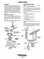
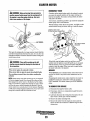
THERMOSTAT
RAW WATER INTAKE STRAINER
A thennostat, located near the manifold at the front of the
engine, controls the coolant temperature as the coolant
continuously flows through the closed cooling circuit When
the engine is first started, the closed thennostat prevents
coolant from flowing (some coolant is by-passed t,brough a
hole in the thennostat to prevent the exhaust manifold from
overheating). As the engine warms up, the thennostat
gradually opens. The thermostat is accessible and can be
checked, cleaned, or replaced easily. Carry a spare thermostat
and gasket
NOTE: Always install the strainer at or below the waterline so
the strainer will always be self-priming.
A clean raw water intake strainer is a vital component of the
engine's cooling system. Include a visual inspection of this
strainer when making your periodic engine check. 'The water
in the glass should be clear.
Perform the following maintenance after every 100 hours of
operation:
1.
2.
3.
4.
5.
6.
7.
Replacing the Thermostat
Remove the cap screws and disassemble the thennostat
housing as shown. "'hen installing the new thennostat and
gasket, apply a thin coat of sealant on both sides of the
gasket before pressing it into place. D6 not over-tighten the
cap screws.
Run the engine and check for nonnai temperatures and that
there are no leaks at the thermostat housing.
Close the raw water seacock.
Remove and clean the strainer filter.
Clean the glass.
Replace the washer if necessary.
Reassemble and install the strainer.
Open the seacock..
Run the engine and check for leaks.
NOTE: Also follow the above procedure after having run luzrd
aground.
If the engine temperature gauge ever shows a higher than
normal reading, the cause may be that silt, leaves or grass
may have been caught up in the strainer, slowing the flow of
raw water tl.trough the cooling system.
WASHER
AIR BLEED PETCOCK
FOR PUSHING AIR FROM THE
COOLING SYSTEM
GASKET
USE HI-TACK SEALANT
STRAINER _...-,.....
r
FIl;TER
i..)..l::,.=-
""'l'-O-LI
r
THERMOSTAT
ASSEMBLY
.,
~--~
TYPICAL RAW WATER STRAINER
(OWNER INSTALLED)
INCOMING
RAW WATER
SENDOR
SEACOCK
Engines & Generators
15
INSPECT AND
CLEAN EVERY
100 HOURS
COOLING SYSTEM
RAW WATER COOLING CIRCUIT
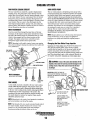
RAW WATER PUMP
The raw water flow is created by a positive displacement
impeller pump. TIus pump draws water directly from the
ocean, lake, or river from a thru-hull opening through a hose
to the water strainer. The raw water passes from the strainer
through the pump to the heat exchanger (through the heat
exchanger tubes) where it cools the engine's circulating fresh
water coolant. The raw water is then discharged into the
water-injected exhaust elbow, mixing with, and cooling the
exhaust gasses. This nllxture of exhaust gas and raw water is
driven through the stern tube and overboard.
The raw water pump is a self-priming, rotary pump with a
non-ferrous housing and a Neoprene impeller. The impeller
has flexible blades which wipe against a curved cam plate
within the impeller housing, producing the pumping action.
On no account should this pump be run dry. There should
always be a spare impeller and impeller cover gasket aboard
(an impeller kit). Raw water pump impeller failures occur
when lubricant (raw water) is not present during engine
operation. Such failures are not warrantable, and operators
are cautioned to make sure raw water flow is present at
start-up. The raw water pump should be inspected
periodica1ly for broken or torn impeller blades. See
MAINTENANCE SCHEDULE.
HEAT EXCHANGER
Cool raw water flows through the inner tubes of the heat
exchanger. As the engine coolant passes around these tubes,
the heat of the interna1 engine is conducted to the raw water
which is then pumped into the exhaust system and discharged. The engine coolant (now cooled) flows back
through the engine and the circuit repeats itself.
NOTE: Should a failure occur with the pumps internal parts
(seals and bearings), it may be more cost efficient to
purchase a new pump and rebuild the original pump as
a spare.
NOTE: Operating in silty and/or tropical waters may require
that a heat exchanger cleaning be perfonned more often then
every 1000 hours.
Changing the Raw Water Pump Impeller
Close the raw water intake valve. Remove the pump cover
and, using an impelleJ;' puller, screw drivers, or pliers,
carefully pry the impeller out of the pump. Insta1l the new
impeller and gasket. Move the blades to confonn to the
curved cam plate and push the impeller into the pumps housing. When assembling, apply a thin coating of lubricant to
the impeller and gasket. Qpen the raw water intake va1ve.
A CAUTION: If any of the vanes have broken off the
impeller, they must be found to prevent blockage in the
cooling circuit. They often can be found in the heat
exchanger.
_-RAW WATER DRAIN
'.lii!L............
CLEAN OUT DEBRIS
INSPECTION: CHECK THE BASE OF
EACH BLADE BY BENDING VIGOROUSLY.
REPLACE THE IMPELLER IF THERE ARE
ANY CRACKS.
HEAT EXCHANGER
CLEAN OUT BOTH ENDS
NEW
REPLACE
ZINC ANODE
CLEAN AND
REUSE
A zinc anode, or pencil, is located in the raw water cooling
circuit within the heat exchanger. The purpose of the zinc
anode is to sacrifice itself to electrolysis action taking place
in the raw water cooling circuit, thereby reducing the effects
of electrolysis on other components of the system. The
condition of the zinc anode should be checked monthly and
the anode cleaned or replaced as required. Spare anodes
should be carried on board.
LIGHTLY GREASE THE
PUMP CHAMBER, a-RING,
AND IMPELLER WITH
GLYCERIN.
NOTE: Electrolysis is the result of each particular installation
and vessel location; not that of the engine.
INSPECT THE a-RING
AND fMPELLER. REPLACE
IF THEY SHOW SIGNS
OF WEAR.
NOTE: The threads of the zinc GJwdes are pipe threads and do
not require sealant. Sealant should not be used as it may
insulate th~ zinc from the metal of the heat exchanger
housing preventing electrolysis action on the zinc.
Engines & Generators
16
ENGINE LUBRICATING OIL
When installing the new oil filter element, wipe the filter
gasket's sealing surface on the bracket free of oil and
apply a thin coat of clean engine oil to the rubber gasket
on the new oil filter. Screw the filter onto the threaded oil
filter nipple on the oil filter bracket, and then tighten the
filter firmly by hand..
ENGINE OIL CHANGE
1. Draining the Oil Sump. Discharge the used oil through
the sump drain hose (attached to the front of the engine)
while the engine is warm. Drain the used oil completely,
replace the hose in its bracket, and replace the end cap
securely.
NOTE: Thread size for the lube oil drain hose capped end
is 114NPT.
Always observe the used oil as it is removed. A
yellow/gray emulsion indicates the presence of water in
the oil. Although this condition is rare, it does require
prompt attention to prevent serious damage. Call a
qualified mechanic should water be present in the oil.
Raw water present in the oil can be the result of a fault in
the exhaust system attached to the engine andlor a
siphoning of raw water through the raw water cooling
circuit into the exhanst, filling the engine. This problem
is often caused by the absence of an anti-siphon valve, its
poor location or lack of maintenance.
2. Replacing the Oil Filter. When removing the used oil
filter, you may find it helpful and cleaner to punch a hole
in the upper and lower portion of the old filter to drain
the oil from it into a container before removing it. This
helps to lessen spillage. A small automotive filter wrench
should be helpful in removing the old oil filter.
NOTE: Do not plUtch this hole without first loosening the
filter to mdke certain it can be renwved.
Place some paper towels and a plastic bag around the
filter when unscrewing it to catch any oil left in the filter.
(Oil or any other fluid on the engine reduces the engine's
cooling ability. Keep your engine clean.) Inspect the old
oil filter as it is removed to make sure that the rubber
sealing gaSket comes off with the old oil filter. If this
rubber sealing gasket remains sealed against the filter
bracket, gently remove it.
NOTE: The engine oil is cooled by engine coolant flowing
through passages in the oil filter bracket housing assembly.
A WARNING: Used engine oil contains harmful
contaminants. Avoid prolonged skin contact. Clean skin
and nails thoroughly using soap and water. Launder or
discard clothing or rags containing used oil. Discard
used oil properly.
NOTE: Generic filters are not recommended, as the
material standards or diameters of important items on
generic parts might be entirely different from genuine
parts. Immediately after an oil filter change and oil fill,
run the engine to make sure the oil pressure is normal
and that there are no oil leaks around the new oil filter.
3. Filling the Oil Sump. Add new oil through the oil filler
cap on the top of the engine or through the side oil fill.
After refilling, run the engine for a few moments while
checking the oil pressure. Make sure there is no leakage
around the new oil filter or from the oil drain system, and
stop the engine. Then check the quantity of oil with the
lube oil dipstick. Fill to, but not over the high mark on
the dipstick, should the engine require additional oil.
LUBRICATION DIAGRAM
Oil PRESSURE
SENDOR
OIL PRESSUm;--1Io-::rfm"~
SWITCH
Oil FIlTER
Oil PRESSURE
RELIEF VALVE
FOR EXTENSION
114" NPT
OIL PUMP
REMOVE USING AN BMM (17116'? SOCKET
TO DRAIN THE OIL OR PUMP THE WARMED
OIL UP THRU THE HOSE.
Engines & Generators
17
REMOTE OIL FILTER (OPTIONAL)
REMOTE OIL FILTER KIT PN#040078
NOTE: Westerbeke is not responsible for engine failure due to
INSTALLATION
incorrect installation of the Remote Oil Filter.
This popular accessory is used to relocate the engine's oil filter from the engine to a more convenient location such as an
c-ngine room bulkhead.
NOTE: Refer to ENGINE OIL CHANGE in this manual for
instructions on removing the oil filter.
'ifb install, snnply remove the engine oil filter and thread on
WESTERBEKE's remote oil filter kit as shown. Always
install this kit with the oil filter facing down as illustrated.
Contact your WESlERBEKE dealer for more information.
APPLY ATHIN COAT OF CLEAN OIL TO THE O-RING WHEN
INSTALLING THIS KIT. THREAD THE KIT ON, THEN HAND
TIGHTEN AN ADDmONAl3f4 TURN AFTER THE O-RING
CONTACTS THE BASE.
A CAUTION: His vital to Install the oil lines correctly. If the 011 flows In the reverse direction, the bypass valve in the filter assemhly will prevent the oil
from reaching the engine causing an Intemal engine
failure. If there Is no oil pressure reading, shutdown
Immediately and check the hose .conrnec~tiollS.
FASTEN SECURELY TO A
(SCREWS ARE OWNER
THE IN CONNECTION HOSE
MUST ATTACH TO THE OUT
CONNECTION AT THE
-oE---RI'Mnn: OIL FilTER.
THE OUT CONNECTION
MUST ATTACH TO THE IN
CONNECTION ATTHE
REMOTE OIL FILTER.
APPLY ATHIN COAT OF CLEAN OIL TO THE FILTER
GASKET WHEN INSTALLING. AFTER THE RLTER
CONTACTS THE BASE, TIGHTEN IT AN ADDITIONAL
Engines & Generators
18
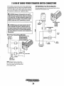
STARTER MOTOR
DESCRIPTION
The starter is a new type, small, light-weight and is called a
high-speed internal-reduction starter. The pinion shaft is
separate from the motor shaft; the pinion slides only on the
pinion shaft. A reduction gear is installed between the motor
shaft and a pinion shaft. The pinion sliding part is not
exposed outside the starter so that the pinion may slide
smoothly without becoming fouled with dust and grease. The
motor shaft is supported at both ends on ball bearings. The
lever mechanism, switch and overrunning clutch inner circuit
are identical to conventional ones.
TERMINALS --~
~~---(M)
TERMINAL
IGNITION
TERMINAL
SOLENOID
To test the ignition circuit, locate the ignition(s) terminal (it
is one of the small terminal studs and is wired to the ignition
circuit). Use a screwdriver, don't touch the blade, to jump
from that ignition terminal to the positive battery connection
terminal on the solenoid.
MOTOR
TYPICAL
STARTER MOTOR
If the starter cranks, the fault lies with the ignition
REFER TO THE WIRING
DIAGRAM IN THIS MANUAL
circuit.
If the solenoid clicks but nothing happens, the starter
TROUBLESHOOTING
motor is probably faulty.
A WARNING: The following emergency starting
SOLENOID
procedures must not be used with gaSOline engines.
Sparks could cause an explosion and fire.
Prior to testing, make certain the ships batteries are at full
charge and that the starting system wiring connections
(terminals) are clean and tight. Pay particular attention to
the ground wire connections on the engine block.
To check the wiring, try cranking the starter for a few
seconds, never more than 10 seconds at a time, then run your
hand along the wires and terminals looking for warm spots
that indicate resistance. Repair or replace any trouble spots.
">
IGNITION
TERMINAL
~
Using a multimeter, test the voltage between the positive
terminal stud on the start solenoid and the engine block
(ground).
If nothing happens at all, the solenoid is not getting
current.. Check the battery isolation switch and inspect the
If you read 12 volts, the starter is faulty.
wiring connections. it is also possible that the solenoid is
defective.
A WARNING: There will be arching and sparks will
fly when jumping terminals. Be certain the engine
space is free of potentially explosive fumes, especially
gasoline, and that there are NO flammable solvents or
materials stored nearby.
Engines & Generators
19
STARTER MOTOR
EMERGENCY START
A WARNING: When performing these procedures,
Corrosion to the starter brushes and/or the solenoid contacts
can cause the sporadic problem of the engine starting one
time but not another. If corrosion is the problem, the starter
will need. to be rebuilt.
It is however, sometimes possible to get started by taping the
starter lightly with a small hammer.
With the battery switch off and no ignition,. tap lightly on the
starter/solenoid casing as shown, then try to start the engine.
position yourself safely away from the moving parts of
the engine in case the engine starts-up. Also warn
other crew members of the danger.
CAREFULLY NOT TO HIT
/
FITTINGS OR WIRE CONNECTIONS
I
(+) POSITIVE
~~'>J
~]TERMINAl
~/
,..,...~---(M) TERMINAL
TAP LIGHTLY WHERE
\. INDICATED
IGNITION
TERMINAL
Test again by jumping the two large terminal studs. Hold the
screwdriver blade finnly between the studs. Do not allow the
screwdriver blade to touch the solenoid or starter casing, this
would cause a short.
If that fails, tum the battery switch on and have a crew
member turn the ignition on and off rapidly as you tap again
with the hammer., This may loosen the brushes and allow
contact to start the engine. When you reach a repair facility,
the starter will need to be repaired.
A WARNING: There will be arching as the full
starting current should be flowing thru the blade of
the screwdriver.
If the starter spins, the solenoid is fanlty.
If the starter fails to spin, the motor is probably faulty.
If no arching occurred, there is no juice reaching the
solenoid.
SERVICE
WESTERBEKE uses a standard starter motor which can be
serviced or rebuilt at any starter motor automotive service
center,
If replacing the starter motor, make certain the new motor is
certified for marine use. Automotive starters do not meet
USCG standards. If in doubt, contact your WESTERBEKE
dealer.
NOTE: Starter motors are either inertia type or pre-engaged.
In the pre-engaged model, the solenoid also moves an arm
that engages the starter motor to the flywheel of the engine.
using a screwdriver to bypass the solenoid on such a starter
will run the motor without engaging the flywheeL Tum the
starter switch on to provide power to the solenoid. Hopefully
it will create enough magneticfieldfor the arm to move even
though the contacts inside the solenoid are bad.
TO REMOVE FOR SERVICE
1. Disconnect the negative battery cable.
2. If necessary, remove any components to gain full access
to the starter motor.
3. Label and disconnect the wiring from the starter. (Do not
allow wires to touch, tape over the terminals).
4. Remove the starter mounting bolts.
5. Remove the starter from the engine. In some cases the
starter will have to be turned to a different angle to clear
obstructions,
Engines & Generators
20
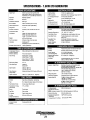
SPECIFICATIONS • 7.6KW ETD GENERATOR
ELECTRICAL SYSTEM
ENGINE SPECIFICATIONS
Engine Type
Aspiration
. Governor
Combustion Chamber
Bore & Stroke
Piston Displacement
Firing Order
Direction of Rotation
Compression Ratio
Dimensions
Diesel, four-cycle, three-cylinder, fresh
water-cooled, vertical in-line overhead valve
mechanism (11 Hp at 1800 rpm maximum)
Naturally aspi rated
Electronic
Swirl type
Starting Battery
Battery Capacity
DC Charging Alternator
Starter
Starting Aid
DC No-Load Current
DC Cranking Current
2.99 x 2.76 inches (76 x 70 mm)
59.09 cubic inches (0.952 liters)
1-3-2
12-Volt, (-) negative ground
800-1000 Cold Cranking Amps (CCA)
51 Amp rated, belt driven
12-Volt, reduction gear, 1.2 KIN
Glow plugs, sheathed type
± 2% of rated amps
195 - 200 Amps (engine cold)
COOLING SYSTEM
Clockwise, when viewed from the front
21:1
Height: 20.4 inches (518.6 mm)
Width: 19.0 inches (482.6 mm)
Length: 27.6 inches (518.6 mm)
Operating Temperature
Fresh Water Pump
Raw Water Pump
Weight
Fuel Consumption
4071bs (184.6 kgs)
0.53 gph (2 Iph) at full rated load
Raw Water Flow,
at 1800 rpm
Fresh water-cooled block, thermostaticallycontrolled with heat exchanger
170 -190° F(77 - 88° C)
Centrifugal type, metal impeller, belt-driven
Positive displacement, rubber irnpeller,
gear-driven
6.5 US gpm (25.8Ipm) (measured
before discharging into exhaust elbow).
Inclination
Continuous 15"
Temporary 25 0 (not to exceed 30 min.)
(fresh water)
System Capacity
4.0 qts (3.79 liters)
Generator Power Take Off
General
1119 hp (maximum)
LUBRICATION SYSTEM
TUNE-UP SPECIFICATIONS
Compression Pressure
(Limit of Difference
Between cylinders)
Valve TIming
General
Oil Filter
Sump Capacity
(not including filter)
Operating Oil Pressure
(engine hot)
Oil Grade
398 psi (28 kg/em') at 280 rpm limit
47.2 psi (3.0 kg/cm')
Intake Opens 17" BTDC
Intake Closes 47" ABDC
Exhaust Opens 51 0 BBDC
Exhaust Closes 13° ATDC
Spill timing (Static)
15° ± .5
Valve Seat Angle
Intake 45"
Exhaust 45°
Engine Speed
1800 rpm 60 Hertz
1500 rpm 50 Hertz
Intake and Exhaust 0.010 inches (0.25 mm)
Valve Clearance
(engine cold)
Injector Pressure
Pressure fed system with external relief valve
Full flow, paper element, spin-on type
3.2 U.S. qts (3.03 liters)
plus filter/cooler assembly
35 - 55 psi (2.5 - 3.8 kg/em')
API Specification CF, CG-4, CH-4 Or CI-4
SAE 30, 10W-30, 15W-40
AC GENERATOR (Single Phase)
General - Single Phase
Voltage - Single Phase
Voltage regulation:
Frequency regulation:
Rating (Volts AC)
1920 + 71 - a psi (135 + 5 - 0 kg/em')
FUEL SYSTEM
General
Open flow, self bleeding - self priming
Fuel
Fuel Injection Pump
No.2 diesel oil (cetane rating of 45 or higher)
In-line plunger (Bosch type)
Fuel Injection TIminQ
(spill timing)
15°±.5 BTDC
Nozzle
Fuel Filter
Throttle type
Spin-on type
Air cleaner
AirFlow
(engine combustion)
Plastic intake silencer
30.2 cfm (0.85 cmm)
Brushless, four-pole, revolving field sealed
lubricated single bearing design.
Reconnectable single phase for 1201240 volts
with solid state voltage regulator.
120 or 1201240 Volts - 60 Hertz
230 Volts - 50 Hertz.
±5% no load to full load.
±0.05 Hertz (5%) no load to lull toad.
7.6 KW - 60 Hertz (1800 rpm)
120 Volts - 31.6 Amps
1201240 Volts - 63.1/31.6 Amps
5.7 KW - 50 Hertz (1500 rpm)
230 Volts - 24.7 Amps
AC GENERATOR (Single Phase)
Air Requirements
200 cfm (5.66 cmm)
(60 Hertz) at 1800 rpm
NOTE: Increase air supply 15% for 50 Hertz operation @ 1500 rpm
Engine Combustion
30.2 cfm (0.85 cmm)
Generator Compartment
120"F (50"C) maximum
Temperature
Compartment Cooling 100 cfm (2.8 cmm)
Engines & Generators
21
7.6KW ETD WIRING DIAGRAM #52414
&217
e;;!
A RElEAS( TO SYSTEM
62:69
f21~·N
B
2'0'0\
C
Ei297
GA
Pi-PIN Z' WAS COHH(CT£O TO KI-PIN 86
GA
DI~GAAM
AOO(O OPTOIN_L REMOTE SIS CaNtlE TIOM
16·A[DI TO 111-16. REMOVE
-RED) BEUHN 112-30 AND
IIl·al (It'YiHTIIf£DI TO IIl- 0
I II-REO) ItEfwHN II)·]Q A 0
U'lO Ill·REO) TO R2-30.
- - ------=:::===-= -,
_
1- 0)--:) --I,.
~tm
~
i:1
~
!ll
I~
16 R[D
,
I
--~
!?-"
~--.. ~J
m
WR"
-+H-_____________-="O~R[~O
_ _ _ _ _ _ _ _ _ _ _ _-----"'-"'-'O""'OR0'-1 '
1' - ---- - -----
---1-+-+---
I
;;
0;
;
~,/~ ___:~;_l:~_;'6_LK__
_
!il
-
!
----*j~JEll/( !
,
~-+~--~---~U
Engines & Generators
22
"-_
: ·';~>?r;'J
_ _ _ _ _ ;_~~il---=-
.18 WHT/GRN
fV.i0;
" , i~
h
~~:
II
li
-- - - -
~
§
GA
~~~~fr.t'..~~p r~~~~ ~~[ I ~~R ~~:P~aS~~rkWIlWiG
tl6
8L~
/
[\1' ",',,""
-yj~~
=~
,,
,
I
,
GA
ENGINE ADJUSTMENTS
NOTE: WESTERBEKE recommends that the following engine adjustments be performed by a competent engine mechanic. The infonnation
below is provived to assist the mechanic.
DRIVE BELT ADJUSTMENT
TORQUING THE CYLINDER HEAD BOLTS
For your safety, WESTERBEKE generator models come
equipped with belt guards that cover over the belt(s) on the
front of the engine. ("Out of sight - out of mind." The belt
guard is NOT installed for that purpose.) Operators are
advised that proper inspection, service, and maintenance is
required.
Excessive drive belt tension can cause rapid wear of the belt
and reduce the serviee life of the fresh water pump's bearing.
A slack belt or the presence of oil on the belt can cause belt
slipping, resulting in high operating temperatures.
The drive belt is properly adjusted if the belt can be
deflected no less than 3/8 inch (lOmm) and no more than 112
inch (l2mm) as the belt is depressed with the thumb at the
midpoint between the two pulleys on the longest span of the
belt. A spare belt or belts should always be carried on board.
After the initial break-in period (approximately 50 hours) and
every 500 hours thereafter, the cylinder head bolts should be
re-torqued.
Tighten the cylinder head bolts according to the sequence
shown. Make sure the engine is cold when this is done.
Before applying the specified torque to the bolt, loo§crr it
114 to 112 of a tum and then apply the torque. Follow this
proeedure according to the numbered sequence shown in the
illustration to the right.
Bolts #1, 2, and 3, (12mm socket) 14 22 ft-Ib
Bolts #4, 5, 6, 7, 8, (14mm socket) (54 -- 61 ft-Ib)
Rockershaft Hold Down Bolts - 12mm socket (11 - 16 ft-Ib).
A
WARNING: Never attempt to check or adjust the
drive belt's tension while the engine is in operation.
Adjusting Belt Tension
1. Remove the belt guard.
2. Loosen the pivot belt that holds the idler sheave and
loosen the adjusting bolt.
3. With the belt loose, inspect for wear, cracks and frayed
edges.
4. Pivot the idler sheave to the left or right as required, to
loosen or tighten.
5. Tighten the pivot bolt and the adjusting bolt.
6. Replace the guard. Operate the generator for about 5
minutes and then shut the generator down.
7. Remove the guard and recheck the belt tension.
8. Replace the guard.
CYUNDER HEAD BOLT PATTERN
FUEL INJECTORS
In case of severe vibrations and detonation noise, have the
injectors checked and overhauled by an authorized fuel
injection service center. Poor fuel quality, contaminant's and
loss of positive fuel pressure to the injection pump can result
in injector faults. Since fuel injectors must be serviced in a
clean room environment, it is best to cany at least one extra
injector as a spare should a problem occur.
Before removing the old injector, clean the area around the
base of the injector to help prevent any rust or debris from
falling down into the injector hole. If the injector will not lift
out easily and is held in by carbon build-up or the like, work
the injector side-to-side with the aid of the socket wrench to
free it, and then lift it out.
The injector seats in the cylinder head on a copper sealing
washer. TIns washer should be removed with the injector and
replaced with a new washer when the new injector is
installed.
START TO INJECTION PRESSURE
1988 ± 142PSI (140 ± 10KG/CM')
IDLER SHEAVE
NOTE: Refer to the .fi::!:.el injector page in this manual for
additional infonnation.
Engines & Generators
23
ENGINE ADJUSTMENTS
GENERATOR FREQUENCY ADJUSTMENT (HERTZ)
ELECTRONIC GOVERNOR
Once the diesel generator set has been placed in operation,
there may be adjustments required for engine speed (Hertz)
during the engine's break-in period (first 50 hours) or after
this period. A no-load voltage adjustment may also be
required in conjunction with the engine's speed adjustment.
These are not warrantable adjustments as they relate to normal break-in and maintenance.
Frequency is a direct result of engine/generator speed, as
inclicated by the following:
When the generator is run at 1800 rpm, the AC voltage
output frequeucy is 60 Hertz.
When the generator is run at 1500 rpm, the AC voltage
output frequency is 50 Hertz.
Therefore to change the generator's frequency, the engine
speed must be changed. To accomplish the frequency change,
pelform the following:
1. With the engine stopped, connect the AC output leads to
the AC terminal block in accordance with the AC voltage
connections diagram specified for your generator set, and
change the Hertz circuit connection to the capacitor.
These connections are shown in the GENERATOR section of this manual. .
The Electronic Governor regulates the engine speed by
sensing the engine's RPM with a magnetic pick-up at the
flywheel. The governor's controller continuously monitors
the engines speed and if there is any discrepancy, the
controller signals the actuator and the actuator adjusts the
engine to the desired speed electronically.
Actuator
The following instructions are for adjusting or replacing
the actuator.
1. Shut-off the DC power to the generator.
2. Disconnect the actuator wires frOm fue wiring harness.
3. Measure the distance between the actuator and the engine
mounting surface as shown.
A WARNING: Before starting the engine make
certain that everyone is clear of moving parts! Keep
away from pulleys and belts during test procedures.
2.
3.
In the control box on the generator is located the
Electronic Control Unit (ECU). Switch #1 contois
engine speed/generator frequency. ON for 50 Hz
and OFF for 60 Hz. Select the correct switch position
for the desired operating hertz.
ACTUATOR
JAM NUT
MEASURE FOR
REFERENCE
Start the engine and observe generator hertz and no
load AC voltage output. Adjust no load AC out put
as needed. Refer to page 38 of this manual.
WHEN CHANGING THE GENERATORS
FREQUENCY (50160 HZ) SWITCH 11
ON THE CONTROL PANEL ECU
BOARD MUST 8E SWITCHED:
ON FOR 50 HZ AND OFF FOR 60 HZ.
ENGINE MOUNTING
hrnmt--I SURFACE
4. Back-offthe 1 7/16" jam nut and unscrew fue actuator.
5. Apply a small amount of teflon sealant to the replacement
actuator and screw the actuator into the engine's
mounting boss. Maintain the same distance between the
actuator and the engine mounting surface as previously
measured Secure the actuator's position with the jam nut
(The standard clistance is 13/16' to 7/8").
6. Reconnect the actuator wires and test the unit
SWITCHES
SCREW/NTO
ORIGINAL MEASURE
3/16" TO 7/8"
STANDAilD
NOTE: For additional infomw.tion and Electronic Governor
Troubleshooting, refer to your WESTERBEKE Service Manual.
Engines & Generators
24
ENGINE ADJUSTMENTS
VALVE CLEARANCE ADJUSTMENT
Re-install the glow plugs (use anti-seize compound on the
threads) and assemble the rocker cover and rocker cover
bolts. See TIGHTENING TORQUE SCHEDULE in this
manual.
NOTE: Retorque the cylinder head bolts before adjusting the
engine's valves. See TORQUING THE CYLINDER HEAD
BOLTS.
ENGINE COMPRESSION
A WARNING: Adjust the valve clearance when the
Check the compression pressure. To do this warm the engine,
remove all fuel injectors, or glow plugs, disconnect the fuel
shut-off solenoid wire, and install a compression adapter in
the injector hole or glow plug hole. Connect a compression
tester on the adapter and crank the engine with the starter
motor until the pressure reaches a maximum value. Repeat
this process for each cylinder. Look for cylinders with dramatically (at least 20%) lower compression than the average
of the others. Compression pressure should not differ by
more than 35.5 psi (2.5 kg/cm2) at 280 rpm.
engine Is cold. Valves are adjusted by cylinder In the flf~
Ing order of the engine. Tighten the cylinder head bolts
to the specified torque before adjusting the valves.
Pull off the air breather pipe from the rocker cover and take
off the rocker cover bolts and the rocker cover to expose the
rocker shaft and valve assembly.
Remove the glow plugs from each of the cylinders to enable
the crankshaft to be easily rotated by hand to position each
cylinder for valve adjustment.
Valves are adjusted with the cylinder in the piston being
adjusted at Top Dead Center (TDC) of its compression
stroke. Each cylinder is adjusted following the engine's firing
order (1-3-2 for WESTERBEKE three cylinder engines).
Valve adjustment beginning with cylinder #1. Rotate the
crankshaft slowly and observe the operation of the valves for
cylinder #1. Watch for the intake valve to open indicating the
piston is on it's intake stroke (the piston is moving down in
the cylinder). Continue to rotate the crankshaft slowly and
look for the intake valve to close. This indicates the piston is
now starting it's compression stroke (the piston is moving up
in the cylinder towards IDC).
Align the IDC mark on the crankshaft front pulley with the
timing marker on the front gear case cover when positioning
the #1 Piston at IDC of it's compression stroke. Confirm this
by rotating the crankshaft approximately 20 degrees before
and after this point and the two valves for the #1 cylinder
should not move.
A
~
~
I
Standard compression pressure 398 IbIln2 at 280 rpm (28.0 k!!1cm2)
If a weak cylinder is flanked by healthy cylinder, the problem
is either valve or piston related. Check the valve clearances
for the weak cylinder, adjust as needed and test again. If the
cylinder is still low, apply a small amount of oil into the
cylinder to seal the rings and repeat the test. If compression
comes up - the rings are faulty.
Abnormally high readings on all cylinders indicates heavy
carbon accumulations, a condition that might be
accompanied by high pressures and noise.
NOTE: In case of severe vibrations and detonation noise, the
cause may be fuel injector problems, see FUEL INJECTORS. Poor fuel quality, contaminates and loss ofpositive
fuel pressure to the injection pump will result in injector
faults.
When re-installing the glow plugs use anti-seize compound.
VALVE CLEARANCE
COMPRESSION TESTER
0.25 mm (0.010 in)
COLD ENGINE
Adjust the valves in #1 cylinder for both intake and exhaust.
Proceed to the next cylinder in the firing order.
Rotate the crankshaft 240 degrees in the normal direction of
rotation and adjust the next cylinder's valves in the firing
order. Rotate the crankshaft another 240 degrees and adjust
the valves of the next cylinder in the firing order.
Adjust each valve's clearance by insertIng a O.OlOin
(0.25mm) feeler gauge between the rocker arm and the valve
stem. Make sure to adjust all valves while the engine is cold.
Engines & Generators
25
ENGINE ADJUSTMENTS
NOTE: WESTERBEKE recommends that the following engine adjustments be peiformed by a competent engine mechanic. The information
below is provided to assist the mechanic.
Injection Pump Timing Adjustment (Spill Timing)
INJECnON PUMP
If your engine's fuel injection timing is not properly adjusted,
the engine will not operate properly, and may be difficult to
start. Have the injection pump delivery rate checked by a
well-established fuel injection shop. Adjust the injection as
follows:
UNION
COLLAR
Q-RING
NOTE: The injection pump fuel rack needs to be in the full
fuel delivery position when peiforming this spill timing. To
do this, unscrew the fuel shut off solenoid and remove the
side cover to expose the injection pump fuel rack. Manually
move the fuel rack to thefuUfuel delivery position (move
fully to the left) secure it in this position then proceed.
1. Remove the high pressure fuel line from between the
No. 1 injector and the No.1 fuel delivery valve holder.
2. Remove the No. 1 fuel delivery valve holder over
"0" ring and remove the delivery valve spring beneath
the holder.
3. Reinstall only the delivery valve holder and reattach the
high pressure fuel line to the delivery holder. Attach it so
that the end that would connect to the fuel injector is
pointing away from the engine fuel will flow from this
line during the timing check.
Rotate the engine's crankshaft in its normal direction of
rotation to position piston No. 1 at the beginning of its
compression stroke.
Move the throttle lever to its full open position and operate
the electric lift pump. Slowly rotate the crankshaft clockwise
(as viewed from the front), catching the fuel from the No.1
fuel line, until the instant the fuel completely stops flowing
(no drips). At this instant, the 15° BTDC timing mark on the
crankshaft pulley should be directly aligned with the timing
indicator on the front of the gear case ± .5 degrees.
If the specified injection timing (15° BIDC) cannot be
attained, adjust the timing by increasing or decreasing the
thickness of shim material under the injection pump's
mounting flange to change the injection timing point.
Changing the shim thickness by 0.004 inch (O.Olmm)
changes the injection timing by approximately one degree.
To advance the timing, decrease the shim thickness, as
required. To retard the timing. increase the shim thickness, as
required. Refer to your Generator's Parts List for shim part
numbers.
DELIVERY
VALVE
STOP WIRE---I
BRACKET
PLUNGER
BARREL
CONTROL RACK
SLEEVE
TAPPET
ROLLER
PLUNGER
CRANKSHAFT
PULLEY
TIMING MARKS
TIMING POINTER
Engines & Generators
26
ENGINE ADJUSTMENTS
NOTE: WESTERBEKE recommends that the following engine adjustments be peiformed by a competent engine mechanic. The information
below is provided to assist the mechanic.
OIL PRESSURE
TESTING GLOW PLUGS
The engine's oil pressnre,is constantly monitored by the control
paneL The red light will illuminate and the generator will
shutdown if the oil pressure fall below 5 psi. Do not restart the
generator without checking the oil and finding the problem.
To inspect the plug, remove the electrical terminal connections, then unscrew or unclamp each plug from the cyIinqer
head. Thoroughly clean each plug's tip and threads with a
soft brush and cleaning solution to remove all the carbon and
oil deposits. \X/hile cleaning, examine the tip for wear and
bum erosion; if it has eroded too much, replace the plug.
NOTE: A newly started, cold engine can have an oil pressure
reading upwa~ds of 60 psi. A warmed engine can have an oil
pressure reading as low as 35 psi. These readings will vary
depending upon the temperature ofthe
and the load
placed on the generator.
LOW OIL PRESSURE
The specified safe minimum oil pressure is 4.3 - 1.4 psi(0.3 0.1 kg/cm2l. An oil pressure of 5 PSI will shut the engine
down. A gradual loss of oil pressure usually indicates worn
bearings. For additional information on low oil pressure readings, see the ENGINE TROUBLESHOOTING chart.
An accurate way to test glow plugs is with an ohmmeter.
Touch one prod to the glow plug's wire connection, and the
other to the body of the glow plug, as shown. A good glow
plug will have a 0.4 - 0.6 ohm resistance. This method can be
used with the plug in or out of the engine. You can also use
an anuneter to test the power drain (5 - 6 amps per plug).
A WARNING: These glow plugs will become very hot
to the touch. Be careful not to burn your fingers when
testing the plugs.
TESTING OIL PRESSURE
~==rc;;;;;;==~==~L
To test oil pressure, remove the oil gallery 'T' plug and
install a mechanical oil pressure gauge in its place. After
warming up the engine, read the oil pressure gauge.
OIL PRESSURE
35.0 Ib/irr(3.8 kg/cnr) or more al1800 rpm
(depending on temperature and load)
SENSOR & GAUGE
9 -13 ft-Ib (1.2 -1.8 m-kg)
TERMINAL
END
TESTING AGLOW PLUG
WITH AN OHMMETER
,-_...I.I-_....:.loo._ _
DO NOT KEEP A GLOW
PLUG ON FOR MORE
THAN 30 SECONDS.
TIP
TESTING A GLOW PLUG
USING ATEST LIGHT
TESTING OIL PRESSURE
Glow Plug Tightening Torque
7 -11-ft-Ib (1.0 -1.5 m-kg)
+
Re-install the plugs in the engine and test them again. The
plugs should get very hot (at the terminal end) within 7 to 15
seconds. If the plugs don't heat up quickly, check for a short
circuit. When reinstalling the glow plugs, use anti-seize compound on the threads.
Engines & Generators
27
FUEL INJECTORS
REMOVING THE INJECTORS
Inspecting Spray Pattern
NOTE: Injector must be serviced in a "clean room" environment.
1. Operate the hand lever of the nozzle tester at intervals of
one stroke per second to check if the fuel is injected correctly in its axial direction. A nozzle is defective if it
injects fuel in an oblique direction or in several separate
strips. Also, a spray in the form of particles indicates a
defect. These defects may sometimes be caused by clogging with dust and, therefore, all parts should be carefully
cleaned before reassembly. (Care should be taken not to
expose ones skin to this spray as it may penetrate the skin
and cause infection.)
1. Disconnect the high pressure lines from the injectors and
loosen the lines at their attachment to the injection pump
and move them out of the way of the injectors. Avoid
bending the lines.
2. Using a 17mm long socket, remove the fuel return line in
its entirety from the top of the injectors. Take care not to
10se the two sealing washers and banjo bolt that attaches
the fuel return line to each injector.
myI WI
NOTE: Clean the area around the base of the injector
prior to lifting it out of the cylinder head to help prevent
any rust or debris from falling down into the injector
hole. If the injector will not lift out easily and is held in
by carbon build up or the like, work the injector side to
side with the aid of the 17mm deep socket wrench to free
it and then lift it out.
~il NORMAL
Ilil
11,111
1
1'1 11
:;:1;\
3. The injector seats in the cylinder head on a copper seal-
/
<i
"~ .FAULTY
~Il,\ fAULTY
I.
~~
,:~~
II
~,
...
'II
,(I,
CHATTERING TEST
'"
2. Apply the pressure of 1635 Ib/in2 (115 kg/cm2) to nozzle
ing washer. This washer should be removed with the
injector and replaced with a new washer when the injector is reinstalled.
by operating the hand lever, and check the drips from the
nozzle tip. If it drips or has a large accumulation of fuel
on the bottom, it is considered defective and should be
repl~ced. A very small amount of fuel may sometimes
remain on the tip of the nozzle; however, this does not
indicate a defect.
INJECTION TESTING
1. Using the nozzle tester, check the spray pattern and injection starting pressure of nozzle and, if it exceeds the
limit, adjust or replace the nozzle. When using nozzle
tester, take the following precautions:
NORMAL
A CAUTION: The spray Injected from the nozzle Is
DRIP TEST
01 such velocity that it may penetrate deeply into the
skin of fingers and handsi destroying tissue. If it
enters the bloodstream, it may cause blood poisoning.
The injection starting pressure for the injectors is adjusted by
increasing or decreasing the thickness of the adjusting shim.
The shim has 10 different thicknesses for every 0.0020 in
(0.05 mm)~ between 0.0049in (l.25mm).to 0.0669in (1.7mm)
With each 0.0020in (0.05mm) increase, injection pressure is
increased approximately 71.1 Ib/in2 (5.0 kg/cm"). When
replacing the shim, grip the retaining nut in a vise and
remove the body with a ,,,,rench. Tighten the retaining nut to
the specified torque.
a. If the diesel fuel of the nozzle tester is discolored,
replace it. At the same time, clean or replace the filter.
b. Set the nozzle tester in a clean place where there is no
dust or dirt.
c. Mount the nozzle and nozzle holder on the nozzle
tester.
d. Use the fuel at the approximate temperature
of 680 F (200 C)
e. Operate the hand lever of nozzle tester several times to
bleed the air in the nozzle line, then move the hand
lever at intervals of one stroke per second while reading the injection starting pressure.
SHIM THICKNESS
ADJUSTING
SHIM
INJECTION PRESSURE
1920 PSI
NOZZLE
TESTER
Engines & Generators
28
I
ENGINE TROUBLESHOOTING
The following troubleshooting table describes certain
problems relating to engine service, the probable causes of
the problems, and the recommendations to overcome these
problems.
Problem
START BUDON depressed, no panel
indications.
NOTE: The engine's DC electrical system is protected by a 20 amp
rocker type manual reset circuit breaker mounted on the
generator's control box next to the LCD Display Panel.
Probable Cause
Veriflcation/Remedy
1. Battery Switch not on.
1. Check switch and/or battery connections.
2. Circuit breaker tripped/off.
2. Reset breaker; if breaker trips again, check preheat solenoid
5. Loose battery connections.
4. Check (+) connection to starter solenoid and (-) connection to
circuit and check circuit for shorts to ground.
engine ground stud. Check battery cable connections.
1. Connection to solenoid faulty.
1. Check connection.
2. Faulty solenoid.
2. Check that 12 volts are present at the solenoid connection.
3. Loose battery connections.
3. Check battery connections.
4. Low battery.
4. Check battery charge state.
5. K1 relay.
5. Check K1 relay.
START BUDON depressed; panel
indications OK; starter solenoid OK
fuel solenoid not functioning.
1. Poor connections to fuel solenoid.
1. Check connections.
2. Defective fuel solenoid.
2. Check that 12 volts are present at the (+) connection on the
Generator engine cranks, but does not
start, fuel solenoid energized.
1. Faulty fueling system.
1. Check that fuel valves are open.
1a. Switch to combine house and start batteries.
1b. Replace batteries.
1c. Check fuel lift pump.
1d. Change inlet fuel filter.
START BUDON depressed, no starter
engagement
fuel run solenoid.
2. Preheat solenoid faulty.
Battery runs down.
~
1. High resistance leak to ground.
2. Low resistance leak.
Battery not charging
2. Check solenoid.
1. Check wiring. Insert sensitive (0 - .25 amp) meter in battery
lines. Do not start engine. Remove connections and replace
after short is located.
2. Check all wires for temperature rise to locate the fault.
3. Poor battery connections.
3. Check cable connections at battery for loose connections,
corrosion.
4. DC alternator not charging.
4. Check connections, check belt tension. test altemator. See
DC ELECTRICAL SYSTEM/ALTERNATOR.
1. DC charge circuit faulty.
1. Perform D.C. voltage check of generator charging circuit. See
DC ELECTRICAL SYSTEM/ALTERNATOR in this manual.
2. Alternator drive.
2. Check drive belt tension. Alternator should turn freely. Check
for loose connections. Check output voltmeter. Ensure 12 volts
are present at the Exc. te rminal.
Generator engine stops.
Engine starts, runs and shuts down.
1. Fuel feed pu mp strainer is di rty.
1. Clean strainer (32 IWV only).
2. Switches and/or wiring loose
or disconnected.
2. Inspect wiring for short circuits and loose connections.
3. Fuel starvation.
3. Check fuel supply, fuel valves, fuel feed strainer.
4. 20 Amp circuit breaker tripping.
4. Check for high DC amperage draw during operation.
Ensure breaker is not overly sensitive to heat which would
cause tripping.
5. Exhaust system is restricted.
5. Check for blockage or collapsed muffler.
6. Water in fuel.
6. Pump water from fuel tank(s); change filters and
bleed fuel system.
7. Air intake obstruction.
7. Check air intake filter cartridge.
1. Faulty oil pressure switch.
1. Check oil pressure switch.
2. Water temperature switch.
2. Check water temperature switch.
Inspect switches for proper operation.
Engines & Generators
29
ENGINE TROUBLESHOOTING
Problem
Exhaust smoking problems
VeriflcationJRemedy
Probable Cause
1. Incorrect grade of engine oil.
1. Blue smoke.
1a. Crankcase is overfilled with engine oil (oil is blowing out
through the exhaust).
2. White smoke.
2. Engine is running cold.
3. Black smoke.
3. Improper grade of fuel.
2a. Faulty injector or incorrect injector timing.
3a. Fuel bum incomplete due to high back pressure in exhaust or
insufficient air for proper combustion (Check for restrictions in
exhaust system; check air intake.).
3b. Improperly timed injectors or valves or poor compression.
3e. Lack of air - check air intake and air filter. Check for proper
ventilation.
3d. Overload.
LCD DISPLAYS
1. Battery on.
No LCD Display
1. Check battery.
2. 20 amp breaker off.
2. Turn breaker on.
OH Pressure
1. Oil level low/oil leak.
1. Check oilleve), add oil and repai r leaks.
2. Lack of oil pressure
2. Test oil pressure. )f OK, test oil pressure sendor, inspect oil
3. Ground connection.
3. Check ground connection.
filter, inspect oil pump.
Coolant Temperature
Exhaust Temperatu re
Battery Voltage
4. Faulty control module.
4. Inspect all the plug connections/replace.
1. Check system coolant level.
2. Check water pump drive belt.
1. Add coolant. Check for leaks.
2. Adjust belt tension. replace belt.
3. Faulty Temp sensor.
3. Check sensor/replace.
4. Ground Connection.
4. Check ground circuit.
5. Faulty control module.
1. Check sea water flow.
2. Faulty exhaust temp switch.
5. Check plug connections/replace.
1. Inspect thru hull fitting, hose and strainer. Correct as needed.
2. Test/replace.
3. Ground Connection.
3. Check ground circuit.
4. Faulty control module.
5. Sea water pump.
1. Check alternator drive belt.
4. Check plug connections.
5. Inspect impeller/replace.
1. Adjust tension/replace if worn.
2. Check charge voltage.
2. Check excitation. replace/repair alternator
3. Check battery connections.
3. Check + and - cables from battery to engine.
4. Faulty control module.
4. Check plug connections/replace.
Generator Voltage
1. Check AC voltage output.
1. Adjust voltageitroubleshoot generator for cause.
Generator Frequency
2. Faulty control module.
1. Check engine speed.
2. Check plug connections/replace.
1. Adjust.
2. Check fuel supply.
2. Inspect filters/replace filters. Test fuel pump operation.
LED Display edges tum pink.
3. Amperage load.
3. Check load with amprobe,
1. Compartment ambient temperature
1. Ventiiate compartment.
too high.
NOTE: Heat will often change the color of an LCD display.
This will not effect the operation of the engine.
Engines & Generators
30
ALTERNATORS TESTING/TROUBLESHOOTING
#100RANGEB
TO STARTER SOLENOID
50 AMP MITSUBISHI
ALTERNATOR
VOLTAGE REGULATOR
The integra] voltage regulator is an electronic switching
device which senses the system voltage level and switches
the voltage applied to the field in order to maintain a proper
system voltage.
The regulator design utilizes all-silicon semi conductors and
thick-film assembly techniques. After the voltage has been
adjusted to the proper regulating valve, the entire circuit is
encapsulated to protect the circuit and the components from
possible damage due to handling or vibration.
CASE GROUND
ALTERNATOR TROUBLESHOOTING
Use this troubleshooting section to determine if a problem
exists with the charging circuit or with the alternator. If it is
determined that the alternator or voltage regulator is faulty,
have a qualified technician check it.
REFER TO THE WIRING
DIAGRAM IN THIS
MANUAL FOR ALL
WIRING CONNECTIONS
DESCRIPTION
A WARNING: A working alternator runs hot. Afailed
The following information applies to the standard alternators
that are supplied with WESTERBEKE'S Engines and
Generators.
alternator can become very hot. Do not touch the
alternator until if has cooled.
ELECTRICAL CHARGING CIRCUIT
LOW BATTERY/FAULTY CIRCUIT
The charging system consists of an alternator with a voltage
regulator, an engine DC wiring harness, a mounted DC
circuit breaker and a battery with connecting cables. Because
of the use of integrated circuits (lC's), the electronic voltage
regulator is very compact and is mounted internally or on the
back of the alternator.
It is desirable to test the charging system (alternator and
voltage regulator) using the wiring harness and electrical
loads that are a permanent part of the system and will then
provide the technician with an operational test of the
charging system as well as the major components of the
electrical system.
If the starter only moans or makes a clicking sound instead
of spinning the engine to life it is likely a low battery or a
faulty connection in. the starting circuit and not an alternator
problem.
PRELIMINARY INSPECTION
Before starting the actual alternator and voltage regulator,
testing the following checks are recommended.
1. Make certain your alternator is securely mounted.
2. Check the drive belts for proper tension. Replace the belt
if it is worn or glazed.
3. Check that all terminals, connectors and plugs are clean
and tight. Loose or corroQed connections cause high
resistance and this could cause overcharging,
undercharging or damage to the charging system. Badly
corroded battery cables could prevent the battery from
reaching a fully charged condition.
4. Check the condition of the battery and charge if necessary.
A low or discharged battery may cause false or misleading
readings in the tests.
ALTERNATOR DESCRIPTION
The stator is connected to a three-phase, full-wave bridge
rectifier package which contains six diodes. The bridge
converts the AC generated in the stator to a DC output for
battery charging and accessories,
Power to the regulator and the field of the integral regulator
alternator is provided by the field diode (or diode trio)
package contained in the alternator.
These alternators produce a rated output of 50 or 51 amps.
rated output is achieved at approximately 6000 alternator
rpm at an ambient temperature of 75°F (23.8°C). The
alternators are designed to operate in an ambient temperature
rangenf -400 to 2l2°P(4{)°to iOO°C).
NOTE: An isolator with a diode, a solenoid, or a battery
selector switch is usually mounted in the circuit to isolate
the batteries so the starting battery is not discharged along
with the Muse batteries. If the isolator is charging the
starting battery but not the house battery, the alternator is
OK and the problem is in the battery charging circuit.
Engines & Generators
31
ALTERNATORS TESTING/TROUBLESHOOTING
MEASURING
BATTERY VOLTAGE
TESTING THE ALTERNATOR
ENGINE OFF)
A CAUTION: Before starting tbe engine make
certain tbat everyone is clear of moving parts! Keep
away from sheaves and belts during test procedures.
1. Start the Engine.
2. After the engine has run for a few minutes, measure the
starting battery voltage at the battery terminals using a
multimeter set on DC volts.
a. If the voltage is increasing toward 14 volts, the
alternator is working.
b. If the voltage remains around 12 volts, a problem
exists with either the alternator or the charging circuit;
continue with Steps 3 through 6l
TESTING THE OUTPUT CIRCUIT
MEASURING
BATTERY VOLTAGE
1. Connect the positiye probe to the output terminal B and
(ENGINE RUNNING)
connect the negative probe to ground.
2. Wiggle the engine wiring harness while observing the
voltmeter. The meter should indicate the approximate
battery voltage, and should not vary. If no reading is
obtained, or if the reading varies, check the alternator
output circuit for loose or dirty connections or
damaged wiring.
3. Start the engine.
3. 'fum off the engine. Inspect all wiring and connections.
Ensure that the battery terminals and the engine ground
connections are tight and clean
4. Repeat the same measurement, the negative probe to
ground, the positive probe to B with the engine running.
The voltage reading should be between 13.5 and 14.5
volts. If your alternator is over or under-charging, have
it repa~red at a reliable service shop.
5. If the previous test reads only battery voltage at
terminal B, use the meter to measure the DC excitation
terminaL If 12 volts is not present at exciter terminal R,
inspect the wiring for breaks and poor connections.
Jump 12 volts from a 12 volt source (such as the
battery) and operate the alternator. If the voltage output
is 13-14 volts, .. then the alternator is OK.
4. If a battery selector switch is in the charging circuit,ensure
that it is on the correct setting.
5. Check the battery voltage. If your battery is in good
condition the reading should be 12 to 13 volts.
j"TER~RINALR
TESTING THE OUTPUT
CIRCUIT ENGINE RUNNING
1#16 VlOLETR
TO K·3 RELAY
Engines & Generators
32
ALTERNATORS TESTING/TROUBLESHOOTING
TESTING THE EXCITATION CIRCUIT
CHECKING THE SERVICE BATTERY
1. Connect the positive (+) multimeter probe to the
excitation terminal R on the alternator and the negative
H lead to ground.
2. 'furn the battery switch to the on position and note
the multimeter reading. The reading should be 1.3 to
2.5 volts (see illustration).
Check the voltage of the service battery. this battery should
have a voltage between 13 and 14 volts when the engine is
running. If not, there is a problem in the service battery
charging circuit. Troubleshoot the service battery charging
circuit by checking the wiring and connections, the solenoid,
isolator, battery switch, and the battery itself.
When the problem has been solved and before the alternator
is back in operation, take the time to tighten and clean the
'terminal studs. Also clean the connecting terminals from the
wiring harness.
TESTING THE
EXCITATION
CIRCUIT
(ENGINE
RUNNING)
EXCITER
TERMINAL
ALTERNATOR REPAIR
If tests indicate a failed alternator, it will need to be disas-
sembled and repaired. Any good alternator service shop can
do the job.
NOT~ WESTERBEKE'S Service Manual has detailed
instructions/or the disassembly and repair a/their
standard alternators.
BATTERY CARE
The minimum recommended capacity of the battery used in
the engine's 12 volt DC control circuit is 600 - 900 Cold
Cranking Amps (CCA).
Review the manufacturer's recommendations and then
establish a systematic maintenance schedule for your
engine's starting batteries and house batteries.
• Monitor your voltmeter for proper charging during
engine operation.
• Check the electrolyte level and specific gravity with a
hydrometer. '
• Use. only distilled water to bring electrolytes to a proper
level.
• Make certain that battery cable connections are clean and
tight to the battery posts (and to your engine).
3. 'If the reading is between .75 and 1.1 volts, the
rotor field circuit probably is shorted or grounded.
4. If the reading is between 6.0 and 7.0 volts, the rotor
field circuit probably is open.
S. If no reading is obtained, an open exists in the
alternator·excitation lead or in the excitation circuit of
the regulator. Disconnect the lead from exc terminal R.
Connect the positive multimeter probe to the excitation
lead and the negative multimeter probe to ground.
If the multimeter now indicates an approximate battery
voltage, the voltage regulator is defective and must be
replaced. If no voltage is indicated, check the
excitation circuit for loose or dirty connections or
damaged wiring.
OUTPUT TERMINAl
EXCITER
TESTING THE
EXCITATION
CIRCUIT
ENGINE
RUNNING
TERMINAL
R
',I
"
Engines & Generators
33
7.6 KW BT SHORE POWER TRANSFER SWITCH CONNECTIONS
230 Volt/5D Hertz Two Wire Configuration
If the installer connects shore power to the vessel's AC circuit, this must be done by means of the SHORE POWER!
Notice the repositioning of the white ground lead on the terminal block to the generator case.
OFF/SHIPS GEN. Set the transfer switch shown in the diagrams to the OFF position. This switch prevents simultaneous connection of shore power to generator output.
,
, 23DV5DHz
A
CAUTION: Damage to the generator can result"
utility shore power and generator output are connected
at the same time. This type of generator damage is not
covered under the warranty; it is the installer's responsibility to make sure al/ AC connections are correct.
o::=n
0
o
0
0
o
a:::::::D
Ship to Shore Switch'
PN3200S
. L1
PN32009
PN 32010
PN32133
~ GENERATOR/SHORE
S
SWITCH
GENERATOR
GROUND
A
CAUTION: Heavy motor leads should be shut off
before switching shore power to generator power or
v!cl?versa because voltage surges Induced by switching with heavy AC loads on the vessel being operated
may cause damage to the exciter circuit components In
the generator.
to
zw
/
, . - .....
'--~-+{1
w
a:
I
C!:I
_
.----3-----+(l3 .
,
~1L1
I
2. I
" ... ....
;'
. SHIP'S
LOAD
.
GENERATOR
(NG1G2.;:.\
I
-
I
I
IL-.
;'- - ,,
---{<j) ~~
Ir----..J~
...... __ ~I
.....
SHORE
t L1
I
T
NJ
SHORE POWER
110V5DHz
II
NOTE: Diagram sOOws connections
for a two-wire, 120 volt system. For a .
three-wire system, use the dotted lines
for the other OOt leg.
Engines & Generators
34
':" GROUND
=
SHlP'S
GROUND
GENERATOR INFORMATION
USE OF ELECTRIC MOTORS
Generator Frequency Adjustment
The power required to start an electric motor is considerably
more than is required to keep it running after it is started.
Some motors require much more current to start them than
others. Split-phase (AC) motors require more current to start,
under similar circumstances, than other types. They are commonly used on easy-starting loads, such as washing
machines, or where loads are applied after the motor is
started,' such as small power tools. Because they require 5 to
7 times as much current to start as to run, their use should be
avoided, whenever possible, if the electric motor is to be driven by a small generator. Capacitor and repulsion-induction
motors require from 2 to 4 times as much current to start as
to run. The current required to start any motor varies with the
load connected to it An electric motor connected to an air
compressor, for example, will require more current than a
motor to which no load is connected.
In general, the current required to start lIS-Volt motors connected
to medium starting loads will be approximately as follows:
Frequency is a direct result of engine/generator speed, as
indicated by the following:
• When the generator is run at 1800 RPM, the AC voltage
output frequency is 60 Hertz.
• When the generator is run at 1500 RPM, the AC voltage
output frequency is 50 Hertz.
Therefore, to change the generator's frequency, the generator's drive engine's speed must be changed. A reconfiguration
of the AC output connections at the generator is also necessary.
MOTOR SIZE
(HPJ
AMPS FOR
RUNNING
(AMPERES)
AMPS FOR
(~TARTING
AMPERES)
1/6
1/4
3.2
4.6
1/3
1/2
5.2
6Mo 22.4*
9.2 to 32.2'
10.4 to 72.8*
14.4 to 29.2*
20.4 to 40.8'
26 to 52
3/4
1
7.2
10.2
13
Generator Maintenance
•
•
•
*NOTE: In the above table the maximum Amps for Starting is
more for some small motors than for larger ones. The reason
for this is that the hardest starting types (split-phase) are not
made in larger sizes.
Because the heavy surge of current needed for starting
motors is required for only an instant, the generator will not
be damaged if it can bring the motor up to speed in a few
seconds. If difficulty is experienced in starting motors, tum
off all other electrical loads and, if possible, reduce the load
on the electric motor.
•
•
Required Operating Speed
•
Run the generator first with no load applied, then at half the
generator's capacity, and finaIly loaded to its full.capacity as
indicted on the generator's data plate. The output volta,ge
should be checked periodically to ensure proper operation of
the generating plant and the appliances it supplies. If an AC
voltmeter or ampere meter is not installed to monitor voltage
and load, check it with a portable meter and amp probe.
Maintaining reasonable cleanliness is important.
Connections of terminal boards and rectifiers may
become corroded, and insulation surfaces may start conducting if salts, dust, engine exhaust, carbon, etc. are
allowed to build up. Clogged ventilation openings may
cause excessive heating and reduced life of windings.
For unusually severe conditions, thin rust-inhibiting petroleum-base coatings, should be sprayed or brushed over all
surfaces to reduce rusting and corrosion. Typical materials
suggested are Daubert Chemical Co. "Non-Rust AC410" and AshIand 'Tectyle 506" or equivalent.
In addition to periodic cleaning, the generator should be
inspected for (a) tightness of all connections, (b) evidence
of overheated terminals and (c) loose or damaged wires.
The drive discs on single bearing generators should be
checked periodically if possible for tightness of screws
and for any evidence of incipient cracking failure. Discs
should not be allowed to become rusty because rust may
accelerate cracking. The bolts which fasten the drive disc
to the generator shaft must be hardened steel SAE grade
8, identified by 6 radial marks, one at each of the 6 corners of the head.
The rear armature bearing is lubricated and sealed; no
maintenance is required. However, if the bearing becomes
noisy or rough-sounding, have it replaced.
Examine bearing at periodic intervals. No side movement
of shaft should be detected when force is applied. if side
motion is detectable, bearings are wearing or wear on
shaft of bearing socket outside bearing has occurred.
Repair Il!ust be made quickly or major components will
rub and cause major damage to generator.
NOTE: When the vessel in which the generator is installed
contains AC equipment of 120 volts only, it is recommended
that the generator's AC tenninal block be configured to provide one 120 volt A C hot leg for the vessel's distribution
panel. This will ensure good nwtor starting response from the
generator.
Engines & Generators
35
7.6KW BT GENERATOR SINGLE PHASE
Circuit Breaker
DESCRIPTION
A circuit breaker is installed on all WESTERBEKE generaThis generator is a four-pole, brushless, self-excited generator
tors. This circuit breaker will automatically disconnect generwhich requires only the driving force of the engine to proator power in case of an electrical overload. The circuit
duce AC output. The copper and laminated iron in the exciter
breaker can be manually shut off when servicing the generastator are responsible for the self-exciting feature of this gentor to ensure no AC power is coming from the generator to
erator. The magnetic field produced causes an AC voltage to
the vessel.
be induced into the related exciter rotor windings during rotation.Diodes located in the exciter rotor rectify this voltage to
NOTE: This circuit breaker is available as a WESTERBEKE
DC and supply it to the windings of the rotating field. This
add-on kit for earlier model generations; contact your
creates an electromagnetic field which rotates through the
WESTERBEKE dealer.
windings of the main stator, inducing an AC voltage which is
supplied to a load. A step down transformer is connected in
parallel to the AC output of the main stator. An AC voltage is
CIRCUIT BREAKER
produced in the auxiliary windings of the transformer and the
main stator and is, in turn, supplied to a full-wave bridge rectifier. The rectifier produces a DC voltage to further excite
WHITEN
the exciter stator windings, enabling the generator to produce
a rated f;.C output.
BREAKER PART NO. 42707
INTERNAL WIRING FOR
12 STUD BT GENERATOR
AC
T
E
R
I
M
I
N
1
iIH:_--~c~
A
L
B
L
o
C
______ J
ORANGE
+
DC
~----------~--------1
GREEN
CI
G
:z
<{
a:
o
AC BLACK
-Kt
K
w
•
@
S
T
U
D
AC~~--------~------------------------------~
YEllOW
D. COMPOUND TRANSFORMER
1. Compound Transformer Windings
2. Compound Transfolmer Windings
3. Compound Transformer Auxiliary Windings
Resistance readings and voltage checks can be accessed
easily for the components in the exciter circuit A, G, C-3 and
D-3 by locating the color coded wires at the connection
points shown on the above schematic. When checking
winding resistance values be sure to lift both of the
component's electrical connections.
G. BRIDGE RECTIFIER
A. EXCITER STATOR WINDING
A-I Exciter Stator Windings
B. EXCITER ROTOR and FIELD
1. Auxiliary Windings (A - B - C)
2. Diodes (6)
3. Rotating Field Windings
4. Pozi Resistor
C. MAIN STATOR
1. Main Stator Windings
2. Main Stator Windings
3. Main Stator Auxiliary Windings
Engines & Generators
36
7.6KW BT GENERATOR TROUBLESHOOTING
Only a few basic tools are necessary for diagnosis and repair.
These are hand tools: an amp probe and a quality volt-ohmmeter capable of reading less than one ohm due to the precision required in reading component winding resistances.
Before attempting any repairs, get a clear an explanation of
the problem as possible, preferably from an individual witnessing the problem. In some cases, this may bring to light a
problem which is related to the method of operation rather
than equipment fault Bring basic repair tools with you on the
initial trip to the problem equipment, such as: diodes and
bridge rectifier, so that if the problem should be found in one
of these easily replaceable parts, the problem can be remedied early and efficiently.
The following troubleshooting chart is designed to give
insight into problems which may be encountered with the BT
brushless generators operating on compound transformer regulation. Owing to the simplicity of the equipment and controls, troubleshooting is ·relatively easy, once the relationship
between cause and effect is understood. Most potential problems are covered in the text of this guide; however should an
omission or an error be found, we would greatly appreciate
'your notifying us of it.
Keep in mind that a basic fundamental knowledge of electricity is required for this troubleshooting, and always remember
that lethal voltages are present in the circuitry; therefore,
extreme caution is essential when troubleshooting a generator.
.TROUBLESHOOTING CHART
REFER TO THE INTERNAL WIRING DIAGRAM WHEN
PERFORMING THE FOLLOWING TESTS.
TROUBLESHOOT THE COMPONENTS IN THE FOLLOWING ORDER:
1. LOW VOLTAGE 60-100 VOLTS AG
COMPONENT CHECKS:
B
A
ROTOR COMPONENTS'
B2. EXCITER ROTOR DIODES
B3. ROTOR FIELO WINDING
B1. EXCITER ROTOR WINDlNG{S) a,b,c.
EXCITER STATOR WINDING
2. NO AC VOLTAGE OUTPUT
MAIN STATOR, ROTOR COMPONENTS, TRANSFORMER
COMPONENT CHECKS:
'
C 1+2 MAIN STATOR 'WINDING
B 4 POSI RESISTOR
B 2 DIODES (4-6 OPEN/SHORTED)
D
B
1+2 COMPOUND TRANSFORMER WINDING
3 ROTOR FIELD WINDING
3. RESIDUAL VOLTAGE EXCITER CIRCUIT FAULTY
.
COMPONENT CHECKS:
A 1-1+2 EXCITER STATOR WINDING(S)
G BRIDGE RECTIFIER
D 3 TRANSFORMER AUX. WINDING
C
3 MAIN STATOR AUX. WINDING
Engines & Generators
37
7.6KW BT GENERATOR SINGLE PHASE
NO-LOAD VOLTAGE ADJUSTMENT
After the no-load hertz adjustment is made, the no-load
voltage may need to be readjusted. In most cases, if the
generator was producing the correct no-load voltage at
the previous hertz setting, it would be correct at the
changed hertz setting.
In the event it needs adjustment, adjust the shim thickness under the laminated steel bar of the transformer.
60 hertz:
no-load voltage, 121 - 124 volts.
50 hertz: no-load voltage, 234 - 238 volts.
d. Load the generator to the rated amperage output corresponding to the hertz speed of the generator.
Rated Loaded Speed
60 hertz: loaded speed, 59.5 60.0 Hertz
50 hertz: loaded speed, 49.5 - 50.0 Hertz
Maximum voltage drop acceptable at full rated output
(amps)
60 hertz:
108 - 110 volts
50 hertz: 215- 220 volts
Should the voltage drop below the proper rate, loaded
excitation can be increased to raise this voltage by
repositioning the connection on the Voltage Connection
Terminal.
TERMINAL BLOCK WIRING CONNECTIONS
Co
1. Voltage adjustment is made with the generator regulation
being governed by the compound transformer.
2. Operate the generator, apply a moderate load momentar~
ily and remove it. Note the voltage output from the gen-
erator's 120 volt leg(s), (230 volt 50 bertz). The no-load
voltage should be between 121-124 volts at 60.0-60.5
hertz (234-238 volts at 50.0-50.5 hertz).
NOTE: The no-load voltage slwuld be adjusted to the voltage produced by the generator once started and a
momentary load should be applied to excite the transformer and then removed. The voltage produced by the
generator after this momentary load is removed is noload voltage.
3. To raise or lower the voltage, shims of varying thickness
(non-conductive material) are placed or removed from
under the steel laminated bar on top of the compound
transformer. The material used for shimming should not
soften at temperatures in the 1760 F (800 C) range. A
small reduction in no-load voltage (l to 3 volts) can
sometimes be accomplished by gently tapping the top of
the laminated steel bar to reduce the gap between the
existing shims and the transformer core.
Winding Connections Needed To Obtain The Proper Voltage and Frequency
3~~~
CHANGING FREQUENCY 50/60Hz
N~~l1
When changing frequency, refer to the digital control
panel pages 7&8 and position switch #1 on the ECU
in the correct position for the hertz selected.
5
5 l1 5 4 4
230V 50Hz
a::::D
b
,0
~
9
9
a::::D
6
&::&
b
120V 50 Hz
0
0
II-r+-:-IICIRCUIT
•
BREAKER
230V50 Hz
10
10
l~CI'CUIT
k±JJ
BREAKER
38
120/240V/6DHz
a::::D
7
N
N L1
N
•
1iI5/2S0V 50Hz
0
b 6 ¢
2
0
10
~,2"V""
Start the engine, monitor AC voltage. Adjust no-load
AC voltage output as needed.
11SV 50Hz
9
12DV5tJ Hz
tlwse installations where the AC circuit has a separate
neutral and ground circuit. This will prevent the unit
from being a ground source in the vessel.
a::::D
7
0
44
5
6
NOTE: The white/green ground wire may be removed in
The frame ground wire must
be moved when changing
from 115 volts and 1101220
volts 50 hertz to 230 volts
50 hertz. From making connections to the AC terminal
block, use terminal ends for
1/4 inch studs that will ,
accept multi-strand copper
wire sized for the amperage
rating from the hot lead connection. The frame ground
wire is white or white with a
green strip. It connects
between the neutral stud
and the generator frame.
4 4
~~~~:,
1. Frequency is a direct result of engine/generator speed:
1800 rpm 60 hertz; 1500 rpm = 50 hertz.
2. To change generator frequency follow the steps below.
a. Configure the AC terminal block for the desired voltage frequency as shown below. Ensure that the case
ground wire is connected to the correct terminal block
neutral ground stud.
b.
5
11DV50Hz
L1
t-:.rih.-l
•
•
CIRCUIT
BREAKER
lir;;lgCIRCUIT
BREAKER
~
II-=-'I-:-II! CIRCUIT
•
•
BREAKER
7.6KW BT GENERATOR SINGLE PHASE
INTERNAL WIRING FOR
12 :lii.iii BT GENERATOR
r-------,
0
I
r-------,
r--------------,
A+:
r--
1
A
B
I
I
-
I
I
B
:
I
: ~ ! 41•
.--+-1--i ~
~ i ! ! 2~ !
DC
GREEN
-
1I
...
3,
I
G
3
2
N
A
8
B
7
I
I
3
I 3
I
I-------J
L
w
Cl
.
z
«a:
:::::::;7'~
I
I
-
I
I WHT/ BLK
.!l~tt-+
~J
I
WHT IGREEN
!
0
AC BLACK
-Kl-AC
1
I
I
I I
c
I I
I
L
2
IL _____________
Jr I
I
L
+
AC
I
I
I I
1>1- ~ )4
ORANGE
C
I
•
•
l
L
o
C
K
@
•
S
T
U
D
YELLOW
a. Apply 12 volt DC excitation to the exciter stator wind-
RESIDUAL VOLTAGE CHECK
1. . Residual Voltage 18 - 22 volts AC.
NOTE: The amount ofno-load voltage produced by the
generator can be an indicator of where in the generator
the problem/fault may lie.
This voltage is the AC voltage produced by the generator
from magnetism in the exciter stator field. This voltage is
measured between the AC neutral and hot leges) with noload on the generator running at its hertz.
The presence of residual voltage is an indication that the
following generator components are OK:
1. Exciter Rotor (B-1 a, b, &c) & (B-2)
2. Rotating Field (B-3)
3. Main Stator (C-l"& C-2)
4. Compound Transformer (D-1 & D-2)
The fault lies in one or more of the following components in the exciter circuit:
A. Exciter Stator (A )
B. Bridge Rectifier (G)
C. Main Stator Auxiliary Windings (C-3)
D. Compound Transformer Auxiliary Winding (D-3)
2. Twelve (12) volts DC excitation of the exciter stator
windings should cause the generator to produce between
125 - 135 volts AC between each hot lead and the neutral. (Twelve volts DC is applied between the lifted (+)
and H leads of the bridge rectifier, + to + and - to -.)
Correct voltage produced with twelve volts DC excitation
indicates the fault is in one or more of the above listed
components B, D aT ·E. If-die generator does not produce
125 - 135 volts AC, then include A and C.
3. The absence of any voltage from the generator indicates a
fault with the main stator windings C-l and C-2 andlor
the compound transformer windings D-l and D-2. Other
failed components that can produce this same no-voltage
output are the posi-resistor in the exciter rotor and four or
more failed diodes in the exciter rotor...
ings as explained in paragraph 2. A fault in the main
stator andlor compound transfoITI1er windings such as a
short will cause the generator engine to load down and
the shorted windings to eventually produce smoke as
the excitation is continued.
4. Voltage output greater than residual and less than the
rated output indicates a fault in the exciter rotor/field B-1,
B-2, B-3. Excitation of the generator as explained in
paragraph 2 should produce a partial rise in voltage output and, when removed, the voltage will return to the
original low output.
JUMPER
START MOTOR
SOLENOID
I'
/
I
,
I
l'''J
POSITIVE (+)
ORANGE
/
::::::i--~
I
/
"
'\:.
BRIDGE ~\
RECTIFIER
+
EXCITING THE GENERATOR
WITH 12 VOLTS
KEEP THE EXCITER CIRCUIT
POLARITY CORRECT:
DCt to Battery at Stader.
DC- to Case Ground
.......
"...
Engines & Generators
39
FROM DC (-J
BLACK
NOTE: Current model bridge
rectifiers are configured
differently, but + and - are
still located at the corners.
7.6KW BT GENERATOR SINGLE PHASE
BRIDGE RECTIFIER
Testing The Bridge Rectifier
For Faults With An Ohmmeter
The bridge rectifier is supplied AC voltage from the auxiliary
windings in the generator stator (c:::-3) and the compound
transformer (D-3). The AC voltage measured across the AC
tenninals of the rectifier during engine operation is as follows:
120 Volts
NILFIL
15
50 Volts AC
(Meter used: Simpson 260)
1. Set the ohmmeter scale on RXI (+ DC) and set the
needle to zero.
2. Connect the positive (+) lead from the ohmmeter to point
#4. Taking the ohmmeter's negative (-) lead, momentarily contact points #1, #2, #3, and #5. The ohmmeter
should register no deflection for any of the points
touched.
120/240 Volts
NIL FIL
15 - 50 Volts AC
Diodes in the rectifier convert this AC voltage to DC and
supply it to the windings of the exciter stator to induce a field
through which the exciter rotor revolves. The DC voltage
measured across the (+) and (-) tenninals of the bridge rectifier during engine operation is as foHows:
120 Volts
120/240 Volts
NIL FIL
NIL FIL ,
8 - 17 Volts DC
8 - 17 Volts DC
Failure of the blidge rectifier will result in a weak field being
produced by the exciter stator windings. A weak field is present, due to the magnetism in the exciter stator, which will
cause the generator to produce residual voltage.
3. Remove the positive (+ ) lead from point #4 and connect
the negative (-) lead to point #4 and, with the positive (+)
lead, momentarily touch points #1, #2, and #3. The ohmmeter's needle should deflect when each point is touched,
showing a passage of meter voltage through the diodes in
the rectifier.
4. Leaving the negative (-) ohmmeter lead on point #4,
touch point #5 with the positive (+) lead. No deflection of
the needle should occur.
5. Place the positive (+) lead of the ohmmeter on point # 1
and the negative (-) lead on point #3. The ohmmeter
should not register any deflection of the needle (no
deflection indicates infinite resistance). Reverse these
connections and the ohnuneter should again register no
deflection.
If the rectifier fails any of the previous tests (1 -4) it is
defective and should be replaced.
NOTE: Different style/model meters may produce opposite
results from the above tests.
BRIDGE RECTIFIER
POINT #1
POINTf3
POINT #4
Engines & Generators
40
7.fiKW BT GENERATOR SINGLE PHASE
The diodes can be easily checked in place with the use of a
common automotive 12-volt high beam headlight bulb, some
jumper leads and the generator's 12 volt starting battery.
A short or an open in a diode can easily be found with the
above without having to unsolder and isolate each diode to
check it with an ohmmeter.
EXCITER ROTORIFIELD
Anxlliary windings group a, band c. Locate the three terminal points on the exciter rotor for these auxiliary winding
groups. Position the exciter rotor as shown in the illustration
and count off the porcelain knobs from the 12 o'clock point
either left or right to Jocate terminal points a, band c.
Measure the resistance value between the pairs of terminal
points A & B, B & C, and C & A. There is no need to unsolder these connections unless a faulty reading appears. If this
occurs, unsolder and verify the winding fault. There should
be no continuity found between any of the three terminal
points and the rotor shaft/case ground.
Auxiliary Windings
NOTE: Attempting to check diodes in place with (JJ1 ohmmeter
will give erroneous readings on the diodes due to the auxiliary winding's connections.
When leads are put across the diode, as illustrated, voltage
passes through the diode allowing the headlight to glow brightly.
1.0 • 1.2 Ohms
RED & WHITE
HIGH BEAM
12 VOLT BULB
GLOWS BRIGHT
Reverse the leads across the diode. The diode should block
voltage passing through it, and the headlight should not glow,
or it may glow faintly.
EXCITER ROTOR
HIGH BEAM 12 VOLT BULB
DOES NOT GLOWjlS VERY FAINT
Rototing Field Wmdings. Refer to the illustration above of
the exciter rotor. The field winding connections are noted as
the (+) and (-) connections of the red & white striped wires.
Measure the resistance value with your ohmmeter between
these two connection points. These connections need not be
unsoldered unless a faulty reading appears. If this occurs
unsolder the connection and verify the resistance reading.
With these connections lifted, there should be no continuity
to the rotor shaft. This would indicate a short to ground with
these field windings.
a. Shciuld the bulb not glow with leads connected in both
directions, the diode is open internally.
b. Should the bulb glow with leads connected in both
directions, the diode is shorted internally.
In both a and b above, the diode should be replaced.
Check the resistance values of the rotating field windings
and the integrity of the resistors connected between tlle
field windings.
Rotating Field Windiltgs 7.0-8.0 ohm. (Reading taken
between the two red & white wires connected to the (+) and
(-) terminals, of the exciter rotor as shown in the illustration.)
. Posi·resistoT. (Infinite readings between both yellow leads
lifted from the (+) and (-) terminals on the exciter rotor.) A
shorted posi-resistor will destroy the rotating field and cause
the AC output voltage to drop to zero.
Diodes. Six diodes are mounted on the exciter rotor; they rectify the AC voltage produced by the three groups of auxiliary
windings to DC voltages and supply this DC voltage to the
rotating field windings.
RESISTANCE VALUE
11'(]HMS rnROUGH THE DIODE
- - - - - 1 1 OHMS
INFINITE
BLOCKING
---If_ I-fa_
INFINITE---....
Engines & Generators
41
7.6KW BT GENERATOR SINGLE PHASE
MEASURING RESISTANCE
Main Stator Windings
1. Group #1. The resistance value is measured between the
lifted lead #4 from the insulated terminal below the trans-
former and lead #6 lifted from the AC terminal block. In
order to totally isolate the stator windings of group #1,
lead #5 should be lifted from the terminal block.
2. Group #2. The resistance value is measured between the
lifted lead #1 from the insulated terminal below the transformer and lead #3 lifted from the AC terminal block. In
order to totally isolate the stator windings of group #2,
lead #2 should be lifted from the terminal block.
Main Stalor Windings
20 - 22 Ohms
3. Main Stator Auxiliary Windings are measured between
the double leads on the AC terminal of the bridge rectifier, unplugged from the rectifier and the double lead central prong connection of the regulator plug.
Main Slator Auxiliary Windings 1.5 -1.8 Ohms
NOTE: No continuity should be found between either of
these winding groups or to the generator case.
Compound Transformer
Group 1 measured between Lead #10 at the AC terminal
block and Lead #4 at the junction box. Lift both leads along
with lead #9 at the terminal block.
Group 2 measured between Lead #8 at the AC tenninal
block and Lead #4 at the junction block. Lift both leads
along with lead #7 at the terminal block.
Compound Transformer Windings 0.019 - 0.021 Ohms
A three connection voltage connection terminal was added to
this circuit located just below the AC terminal block at the
lower left. Isolate the three numbered #1, #2, and #3 red and
white-striped wires coming onto each of the three terminals.
Lift the black and white-striped leads and the green and
white-striped leads off of their connections on the AC terminal block. Measure the resistance value between the #1 red
lead lifted from the terminal strip and the bJack and white
striped lead lifted from the AC terminal block.
Transformer Auxiliarv Windings 4.0 - 4.5 Ohms
VOLTAGE CONNECTION TERMINAL
The addition of the three connection terminal is for the
increase or decrease of full-load voltage output. Should fullload voltage fall below 108 volts, selecting a higher number
terminal strip lead to connect the lead (red or red and white)
will supply a higher AC voltage to the exciter circuit during
full-load conditions, bringing the output voltage of the generatorup.
No-load voltage should be properly adjusted by shimming
the compound transformer: 121 - 124 volts at 60.0 60.5
hertz. The above should not be used as a means of compensating for incorrectly adjusting the generator's no-load vo1t~
age.
NOTE: For engine speedlhert;z adjustment, see ENGINE
ADJUSTMENTS in this manuaL
VOLTAGE CONNECTION TERMINAL
lOW
........-1REPOSITION -- /--.._..
LEADS
HIGH
12 STUD
TERMINAL BLOCK
CIRCUIT
BREAKER
BT SINGLE PHASE (12 STUD)
120/60 VQLT CONFIGURATION
Engines & Generators
42
LAY-UP AND RECOMMISSIONING
GENERAL
A CAUTION: Do not leave the engine's old lubricat-
Many owners rely on their boatyards to prepare th~ir craft,
including engines and generators, for lay-up during the offseason or for long periods of inactivity. Others prefer to
accomplish lay-up preparation themselves.
The procedures which follow will allow you to perform your
own lay-up and recommissioning, or you may use them as a
check list if others do the procedures.
'
These procedures should afford your engine protection during a lay-up and also help familiarize you with the maintenance needs of your engine.
If you have any questions regarding lay-up procedures, call
your local servicing dealer; he will be more than willing to
provide assistance.
Ing oil in the sump over the lay-up period. Lubricating
oil and combustion deposits combine to produce harmful chemicals which can reduce thelile 01 your engine's
internal parts.
FUEL SYSTEM
Top off your fuel tanks with No.2 diesel fuel. Fuel additives
such as BioBor and Sta-Bil should be added at this time to
control algae and condition the fuel. Care should be taken
that the additives used are compatible with the primary fuel
filter/water separator used in the system. Change the element
in your primary fuel filter/water separator, if the fuel system
has one, and clean the separator sediment bowl.
Change the fuel filter elements on the engjne and bleed the
fuel system, as needed. Start the engine and allow it to run
for 5 - 10 minutes to make sure no air is left in the fuel system. Check for any leaks that may have been created in the
fuel system during this servicing, correcting them as needed.
Operating the engine for 5 - 10 minutes will help allow
movement of the treated fuel through the injection equipment
on the engine.
PROPELLER SHAFT COUPLING
The transmission and propeller half couplings should always
be opened up and the bolts removed when the boat is hauled
out of the water or moved from land to water, and during
storage in the cradk The flexibility of the boat often puts a
severe strain on the propeller shaft or coupling or both, while
the boat is taken out or put in the water. In some cases, the
shaft has actually been bent by these strains. This does not
apply to small boats that are hauled out of the water when
not in use, unless they have been dry for a considerable
period of time.
RAW WATER COOLING CIRCUIT
Close the through-hull seacock. Remove the raw water intake
hose from the seacock. Place the end of this hose into a five
gallon bucket of clean fresh water. Before starting the engine,
check the zinc anode found in the primary heat exchanger on
the engine and clean or replace it as required, and also clean
any zinc debris from inside the heat exchanger where the
zinc anode is located. Clean the raw water strainer.
Start the engine and allow the raw water pump to draw fresh
water through the system. When the bucket is empty, stop the
engine and refill the bucket with an environmentally friendly
antifreeze solution slightly stronger than needed for winter
freeze protection in your area.
Start the engine and allow all of this mixture to be drawn
through the raw water system. Onee the bucket is empty, stop
the engine. This antifreeze mixture should protect the raw
water circuit from freezing during the winter lay-up, as well
as providing corrosion protection.
Remove the impeller from your raw water pump (some
antifreeze mixture will accompany it, so catch it in a bucket).
Examine the impeller. Acquire a replacement, if needed, and
a cover gasket. Do not replace the impeller (into the pump)
until recommissioning. but replace the cover and gasket.
FRESH WATER COOLING CIRCUIT
A 50-50 solution of antifreeze and distilled water is
recommended for use in the coolant system at all times. This
solution may require a higher concentration of antifreeze,
depending on the area's winter climate. Check the solution to
make sure the antifreeze protection is adequate.
Should more antifreeze be needed, drain an appropriate
amount from the engine block and add a more concentrated
mixture. Operate the engine to ensure a complete circulation
and mixture of the antifreeze concentration throughout the
cooling system. Now recheck the antifreeze solution's strength.
LUBRICATION SYSTEM
With the engine warm, drain all the lubricating oil from the
oil sump. Remove and replace the oil filter. (Place some
paper towels and a plastic bag around the filter to catch the
oil during its removaL)
When installing the new oil filter, be sure to apply a small
amount of oil on the rubber sealing gasket at the base of the
filter. Fill the sump with the correct amount of oil for your
engine. (Refer to the SPECIFICATIONS section of this manual.) Use an oil with an API specification of CF or CG-4.
Run the engine and check for proper oil pressure and make
sure there are no leaks.
INTAKE MANIFOLD AND THROUGH-HULL EXHAUST
Place a clean cloth, lightly soaked in lubricating oil, in the
opening of the intake manifold to block the opening. Do not
shove the cloth out of sight. (If it is not visible at recommissioning, and an attempt is made to start the engine, you may
need the assistance of a servicing dealer.) Make a note to
remove the cloth prior to start-up. The through-hull exhaust
port can be blocked in the same manner.
Engines & Generators
43
LAY-UP & RECOMMISSIONING
Starter Motor
Spare Parts
Lubrication and cleaning of the starter drive pinion is
advisable, if access to the starter pennits its easy removaL
Make sure the battery connections are shut off before
attempting to remove the starter. Take care in properly
replacing any electrical connections removed from the starter.
Lay-up time provides a good opportunity to inspect your
WESTERBEKE engine to see if external items such as drive
belts or coolant hoses need replacement Check your basic
spares kit and order items not on hand, or replace those items
used during the lay-up, such as filters and zinc anodes. Refer
to SPARE PARTS section of this manual.
Cylinder Lubrication
Recommissioning
If you anticipate a long lay-up period (12 months or more)
The recommissioning of your WESTERBEKE engine after a
seasonal lay-up generally follows the same procedures as
those presented in the PREPARATIONS FOR STARTING
section regarding preparation for starting and normal starts.
However, some of the lay-up procedures will need to be
counteracted before starting the engine.
WESTERBEKE recommends removing the glow plugs or
fuel injectors for access to the cylinders. Squirting light
lubricating oil into the cylinders to prevent the piston rings
from sticking to the cylinder walls. Rotate the engine by hand
two revolutions then replace the glow plugs or injectors.
Make sure you have a replacement if removing the injector
sealing washer for the injector and fuel "return line,
1. Remove the oil-soaked cloths from the intake manifold
Intake Manifold [Gasoline]
2. Remove the raw water pump cover and gasket. and discard
the old gasket. Install the raw water pump impeller
removed during lay-up (or a replacement, if required).
Install the raw water pump cover with a new cover gasket
Clean the filter screen in the flame arrester, and place a clean
cloth lightly soaked in lube oil around the flame arrester to
block any opening. Also place an oil-soaked cloth in the
through-hull exhaust port. Make a note to remove cloths prior
to start-up 1.
3. Reinstall the batteries that were removed during the layup. and reconnect the battery cables, making sure the
terminals are clean and that the connections. are tight.
Check to make sure that the batteries are fully charged.
Intake Manifold and Thru-Hull Exhaust{Diesel]
Place a clean cloth, lightly soaked in lubricating oil, in the
opening of the intake manifold to block the opening. Do not
shove the cloth out of sight. (If it is not visible at recommissioning, and an attempt is made to start the engine, you may
need the assistance of a servicing dealer.) Make a note to
remove the cloth prior to start-up. The through-hull exhaust
port can be blocked in the same manner.
A CAUTION: Wear rubber gloves, a rubber apron,
and eye protection when servicing batteries. Lead acid
batteries emit hydrogen, a highly explosive gas, which
can be Ignited by electrical arcing or a lighted
cigaretfB, cigar, or pipe. Do not smoke or allow an
open flame near the battery being serviced. Shut off
all electrical eqUipment In the viCinity to prevent
electrical arcing during servicing.
BATTERIES
If batteries are to be left on board during the lay-up period,
make sure they are fully charged, and will remain that way,
to prevent them from freezing. If there exists any doubt that
the batteries will not remain fully charged, or that they will
be subjected to severe environmental conditions. remove
the batteries and store them in a warmer. more compatible
environment.
4. Remove the spark plugs. wipe clean, re-gap. and install to
proper tightness [gasoline].
5. Check the condition of the zinc anode in the raw water
circuit and clean or replace the anode as needed. Note that
it is not necessary to flush the antifreeze/fresh water
solution from the raw water coolant system. When the
engine is put into operation, the system will self-flush in a
short period of time with no adverse affects. It is
advisable, as either an end of season or recommissioning
service, to inspect the area where the zinc is located in the
heat exchanger and clear any and all zinc debris from that
area.
A Warning: Lead acid batteries emit hydrogen, a
hlgh/y-explosive gas, which can be ignited by electrical
arcing or a lighted Cigarette, cigar, or pipe. Do not
smoke or aI/ow an open name nIJar the battery being
serviced. Shut off aI/electrical equipment in the
viCinity to prevent electrical arcing during S8rviclng.
Transmission {Propulsion Engine]
6. Start the engine in accordance with procedures described
in the PREPARATIONS FOR INmAL START-UP section of
this manual.
Check or change the fluid in the transmission as required.
Wipe off grime and grease and touch up any unpainted areas,
Protect the coupling and the output flange with an anti-corrosion coating. Check that the transmission vent is open. For
additional information. refer to the TRANSMISSION
SECTION.
Engines & Generators
44
POWER TAKE OFF SYSTEMS
POWER TAKE OFF ADAPTER
A power take off adapter can be attached to the generator
backend. This adapter allows access to the full power of the
engine for a variety of hydraulic and electrical accessories.
The 7.6Kw ETD produces Ilhp at a continuous 1800 rpm
(Shp at 50Hz 1500 rpm). This horsepower can be utilized
either for generator AC output or to operate the power
take off.
Contact your WESTERBEKE DISTRIBUTOR/or additional
information.
REMOVE COVER
-@
POWER TAKE OFF
KIT #34786 (SAE-B)
STUDS AND HARDWARE
HOLD ACCESSORY TO THE
,ADAPTER
~~
@ "
ADAP~
ADAPTER
BOLTS FASTEN
TO GENERATOR HOUSING
/0
,.~
.. ,/.,'U(! ~~.
j{IY/
"
t~·,
0:/ ~~.
o
({
"-
.
HYDRAULIC PUMP
,
(TYPICAL)
OWNER SUPPLIED
.
Engines & Generators
45
::-...
STANDARD AND METRIC CONVERSION DATA
LENGTH-DISTANCE
Inches (in) x 25.4 Millimeters (mm) x .0394 Inches
Feet (tt) x .305 :: Meters (m) x 3.281 Feet
Miles x 1.609 :: Kilometers (km) x .0621 :: Miles
DISTANCE EQUIVALENTS
1 Degree ofLatitude :: 60 Nm 111.120 km
1 Minute of Latitude:: 1 Nm = 1.852 km
VOLUME
s
Cubic Inches (inS) x 16.387:: Cubic Centimeters x .061 =in
Imperial Pints (IMP pt) x .568 :: Liters (L) x 1.76 :: IMP pt
Imperial Quarts (IMP qt) x 1.137 = Liters (L) x.88 ::: IMP qt
Imperial Gallons (IMP gal) x 4.546 :: Liters (L) x .22 =IMP gal
Imperial Quarts (IMP qt) x 1.201 :: US Quarts (US qt) x .833:: IMP qt
Imperial Gallons (IMP gal) x 1.201 US Gallons (US gal) x .833 :: IMP gal
Fluid Ounces x 29.573 = Milliliters x .034 = Ounces
US Pints (US pt) x .473 = Liters(L} x 2.113 = Pints
US Quarts (US qt) x .946 Liters (L) x 1.057 '" Quarts
US Gallons (US gal) x 3.785 = Liters (L) x .264 :: Gallons
MASS-WEIGHT
Ounces (oz) x 28.35 Grams (g) x .035 :: Ounces
Pounds (lb) x .454 :: Kilograms (kg) x 2.205:: Pounds
PRESSURE
Pounds Per SQ In (psi) x 6.895 :: Kilopascals (kPa) x .145 :: psi
Inches of Mercury (Hg) x .4912:: psi x 2.036 = Hg
Inches of Mercury (Hg) x 3.377 Kilopascals (kPa) x .2961 :: Hg
Inches of Water (H20) x .07355:: Inches of Mercury x 13.783 =H20
Inches of Water (H20) x .03613 = psi x 27.684 =H20
Inches of Water (H20) x .248 = Kilopascals (kPa) x 4.026 = H20
TORQUE
Pounds-Force Inches (in-Ib) x .113:: Newton Meters (Nm) x 8.85 =in-Ib
Pounds-Force Feet (ft-Ib) x 1.356 :: Newton Meters (Nm) x .738 =ft-Ib
VELOCITY
Miles Per Hour (MPH) x 1.609 :: Kilometers Per Hour (KPH) x .621 :: MPH
POWER
Horsepower (Hp) x .745 = Kilowatts (Kw) x 1.34 = MPH
FUEL CONSUMPTION
Miles Per Hour IMP (MPG) x .354 ;::; Kilometers Per Liter (Km/L)
Kilometers Per Liter (Km/L) x 2.352 ;;; IMP MPG
Miles Per Gallons US (MPG) x .425 :: Kilometers Per Liter (Km/L)
Kilometers Per Liter (Km/L) x 2.352 ;; US MPG
TEMPERATURE
Degree Fahrenheit (OF) = (oG X 1.8) + 32
Degree Celsius (OC) = (OF - 32) x .56
LIQUID WEIGHTS
Diesel Oil:: 1 US gallon =7.131bs
Fresh Water =1 US gallon", 8.33 Ibs
Gasoline = 1 US gallon:: 6.1 lbs
Salt Water =1 US gallon =8.56 Ibs
Engines & Generators
46
SUGGESTED SPARE PARTS
CONTACT YOUR WESTERBEKE DEALER FOR SUGGESTIONS AND ADDITIONAL INFORMATION
WESTERBEKE RECOMMENDS CARRYING ENOUGH
ENGINE OIL (YOUR BRAND) FOR AN OIL CHANGE
AND A GALLON OF PREMIXED COOLANT.
THERMOSTAT
SPARE DRIVE
BELTS
FUEL SYSTEM
HARDWARE KIT
MOLDED
HOSE KIT
INA CANVAS
CARRYING BAG
IN-LINE
FUEl/WATER
FILTER CARTRIDGE
INJECTOR
SPARE PARTS KITS
WESTERBEKE also offers two Spare Parts Kits,
each packaged in a rugged hinged toolbox.
Kit "A" includes the basic spares.
Kit "B" is for more extensive off-shore cruising.
KIT B
ZINC ANODES
DRIVE BELTS
OIL FILTER
FUEL FILTER
HEAT EXCHANGER GASKET
IMPELLER KIT
KIT A
ZINC ANODES
DRIVE BELTS
OIL FILTER
FUEL FILTER
HEAT EXCHANGER GA~KET
IMPELLER KIT
FUEL SYSTEM HARDWARE KIT
FUEL PUMP INLET FILTER
INJECTOR
OVERHAUL GASKET KIT
GLOW PLUG
FUEL SYSTEM HARDWARE KIT
FUEL PUMP INLET FILTER
Engines & Generators
47
Engines & Generators
WMDW11096/05