1
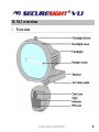
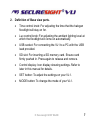
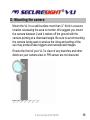
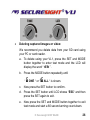
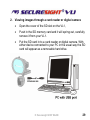
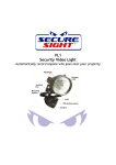
VL1 User’s Manual Version 1.5 Sept 07 Manual Contents: A. Camera kit contents 3 B. VL1 overview 4 C. Definition 6 D. Mounting the camera 13 E. Camera setup – Getting started 14 F. Setting the MODE of your VL1 22 G. Driver and Ulead Photo Explorer installation 27 H. Viewing images via PC or digital camera 28 I. Web Cam Mode 30 J. Web Cam software and enhanced security 32 K. Technical Specifications 33 L. General information and safety 36 M. CE and ROHS compliance 37 © Securesight 2007 E&OE 2 A. Camera kit contents • Model VL1 Lighting Camera • 512Mb SD card • USB lead • Ulead Photo Explorer software and camera driver CD • User Manual © Securesight 2007 E&OE 3 B. VL1 overview 1. Front view © Securesight 2007 E&OE 4 2. Base view © Securesight 2007 E&OE 5 C. Definitions 1. Definitions of Front view parts. • Flood light screw: Used to open or close the flood light case to replace the halogen lamp. • Flood light cover: Open to replace lamp • Floodlight: • Halogen lamp: For lighting purpose, please use the correct voltage and wattage of halogen light for this product. Halogen lamp R7S, Max power: 500W. • Bracket: For mounting the VL1. • AC cable outlet: For connecting the external AC cable to VL1. • Cam Lens: This is the digital camera lens. Use a soft cloth to clear if necessary, • PIR lens: Passive Infrared movement sensor. • TEST Indicator: A red indicator behind the PIR lens which lights when testing the PIR coverage area and flashes during the arming count down time. © Securesight 2007 E&OE 6 2. Definition of Base view parts. • Time control knob: For adjusting the time that the halogen floodlight will stay on for. • Lux control knob: For adjusting the ambient lighting level at which the floodlight will come on automatically. • USB socket: For connecting the VL1 to a PC with the USB lead provided. • SD slot: For inserting a SD memory card. Ensure card firmly pushed in. Press again to release and remove. • Control display: Icon display showing settings. Refer to later in this manual for details. • SET button: To adjust the settings on your VL1. • MODE button: To change the mode of your VL1. © Securesight 2007 E&OE 7 3. Definition of Control display. © Securesight 2007 E&OE 8 • : Still image capture icon. Indicates your VL1 will capture a single image. • : 2 Photos burst capture icon. Indicates your VL1 will capture two consecutive images. • : Image counter to show how many images or videos have been captured. • : Storage status icon. Only present if an external SD card installed. If no icon your VL1 will use its internal built memory. • : Video-capturing icon. Indicates your VL1 is in video capturing mode and will capture 10 second video bursts. • : High-resolution icon. Indicates the VL1 is in highresolution still image capturing mode. © Securesight 2007 E&OE 9 • : Low-resolution icon. Indicates the VL1 is in lowresolution still image capturing mode. • D: Date setting mode. Indicates when your VL1 is in Date setting mode. • T: Time setting mode. Indicates when your VL1 is in Time setting mode. • • : Rubbish bin icon, Indicates the VL1 is in delete mode. : Floodlight control icon, When showing, the floodlight will turn on if the camera sensor detects the light levels are too low. When the Icon is not showing the floodlight is turned on when the photo sensor detects the light level has dropped below the threshold set with the LUX control. • • : Shows the Date and time. : Pressing the SET button will exit the current mode. © Securesight 2007 E&OE 10 4. Picture / Image Capacity High 2.0M 1600x1200 Low 1.3M 1280x1024 AVI QVGA 320x240 Built In memory 8 12 2 16MB 26 40 8 32MB 52 80 16 64MB 104 160 32 128MB 208 320 64 256MB 416 640 128 512MB 832 1280 256 1GB 1664 2560 512 SD card © Securesight 2007 E&OE 11 NOTE: Picture / Image Capacity Chart shows the approximate number of images or video clips that can be stored based on the resolution setting and the size of memory card. These figures may vary depending on the amount of detail in the image. Also, when your memory card is full, your VL1 will begin overwriting the earliest data ensuring you always have the most recent images. Memory Options – Up to 1Gb SD card Your VL1 lighting camera is equipped with 16MB built in SDRAM memory. Please note:- data stored on internal memory may be lost in the event of a power failure. We therefore recommend the use of external memory using the media card slot capable of accepting up to 1GB SD card (sold separately). With no memory card inserted into the slot, the camera will use the built in 16MB SDRAM memory. If a SD card is inserted into the slot then the camera will bypass the built in memory and write to the SD memory. It is not recommended that a card is inserted or removed during operation as this can cause malfunction. The counter display will show the number of images on the built in memory and will change to show the number on a memory card if one is fitted. © Securesight 2007 E&OE 12 D. Mounting the camera Mount the VL1 to a solid surface more than ½” thick in a secure location overseeing the area to monitor. We suggest you mount the camera between 2 and 4 meters off the ground with the camera pointing at a downward angle. Be sure to avoid mounting the camera facing east or west as the rising and setting of the sun may produce false triggers and overexposed images. Ensure the front of your VL1 is clear of any branches and other debris so your camera view or PIR sensor are not obscured. © Securesight 2007 E&OE 13 E. Camera setup – getting started 1. Inserting SD card SD cards must not contain any other images and you must ensure your VL1 is disconnected to AC power when adding or removing an SD memory card. Failure to observe these rules may result in malfunction. • Your VL1 is supplied with a 512Mb SD card. Insert the SD memory card in to the SD card slot completely and in the correct direction as shown on the inside of the housing. • • DO NOT FORCE THE SD CARD To remove the SD memory card, push the SD card in and it will spring out, now pull out the card gently. 2. Connect the VL1 to AC power. (See section L) Please make sure your VL1 is rated for your voltage before connection. Incorrect voltage will damage the camera. This product is intended for 220-240 VAC. © Securesight 2007 E&OE 14 © Securesight 2007 E&OE 15 • Ensure you connect your VL1 in accordance with the wiring diagram. Failure to do so may result in damage to your VL1 and will void your warranty. • We recommend using a supply that you can switch off if required. Once wired correctly, turn on the mains supply. • When connected the VL1 lamp will turn on for approximately 60 seconds whilst self-testing. It is then ready for operation and will begin recording images each time the motion sensor is triggered. Replacing the halogen lamp if faulty CAUTION your lamp will be very hot. • Always disconnect the power to your VL1 before opening. • Release the floodlight screw to open the floodlight cover. • Carefully remove the Halogen lamp – it may be HOT. • Insert a new Halogen lamp making sure you do not touch the lamp with bare skin. Halogen Lamp : Max 500W R7S • Close the floodlight cover and screw together carefully. © Securesight 2007 E&OE 16 2. Settings. You can change the settings on your VL1. The parameters that can be changed and the default values are shown below. Please note after changing any settings the test LED will flash and the unit will count down for approx. 60 seconds before arming. Setting Default Time 00:00 HH:MM Date 04:01:06 MM:DD:YY Flicker frequency 50 Hz 50 / 60 Image capture interval 1 minute 0-60 Resolution High High/Low Image capture method Video Video/Photo Floodlight control Off On/Off Your VL1 can be used straight away but before use you may wish to change some or all of the settings – see the next sections. © Securesight 2007 E&OE 17 3. Set the Data and Time. • After mounting your VL1 (with SD card already fitted if required) connect the camera to the AC power. The camera will turn on automatically and will begin to count down ready to arm. • Press the SET and MODE button together once to enter TEST MODE, the LCD will display the word “ t E S t ”. • Press the MODE button repeatedly untill the LCD displays: “ T, 00-00 “ and are flashing. • Press the SET button repeatedly to set the HOURS • Press the MODE button to confirm. • Now press the SET button repeatedly to set the MINUTES, then press the MODE button to confirm. © Securesight 2007 E&OE 18 • The display will now change to “4.01.06” representing the date in the format MM.DD.YY • Press the SET button to set the MONTH followed by the MODE button to confirm. • Repeat this process to set the Day and Year. • Still images will be stamped with the time and date you set here. NOTE: Settings and images stored on internal memory may be lost in the event of a power failure. Always ensure you reset your VL1 following a loss of power. 4. Setting the flicker frequency 60Hz or 50Hz By adjusting your VL1 to reflect the AC power frequency you will eliminate any flicker effect on captured images. For the UK this must be set to 50Hz. • When VL1 is in TEST MODE, press the MODE button repeatedly until the LCD flashes “ 60HZ ” © Securesight 2007 E&OE 19 • Now press MODE button to change to 50Hz (UK) • Press the SET button to confirm your choice. The LCD will display “ dONE “ and then display “ ESC “ • Press the SET button again to exit and return to TEST MODE. • Press the MODE and SET button together again to leave the TEST MODE. 5. Testing the sensor coverage area In test mode the VL1 allows you to test the coverage area. • After mounting connect your camera to AC power, the camera will turn on automatically. • It will now start to count down to arm – approx 60 seconds. © Securesight 2007 E&OE 20 • Pressing the SET and MODE button together to enter TEST MODE, the LCD will display the word “ t E S t ”. • Whilst in test mode, each time the PIR sensor is triggered a red indicator behind the PIR lens will flash to indicate a trigger. Walk around the coverage area to determine if your camera is suitably mounted. • Adjust the position of your VL1 if necessary and repeat testing until the desired coverage area is achieved. • When you have completed the coverage area testing, press the MODE and SET button together again to leave the TEST MODE. • The VL1 will start a 60 seconds count down again. • Alternatively, when you have finished testing if you leave the VL1 for approximately 5 minutes it will automatically begin the 60 seconds count down. • Please leave the coverage area within 60 seconds to avoid being photographed or videoed. © Securesight 2007 E&OE 21 F. Setting the MODE for your VL1 Press and hold the MODE button until the camera ICON begins to flash. 1. Image capture interval setting: This determines the delay between successive image capture. When set, the VL1 will take a picture when triggered and then wait for the set delay before taking another image even if triggered in that time. • Press the MODE button repeatedly until LCD flashes “ to-xx “ where “xx” represents the minutes e.g. 05 • Press the SET button to increase the interval – when it reaches 60 the value will revert to 0. • If you want continuous recording of either photos or video each time movement is detected, set this interval to 0. • Press the MODE button to confirm and exit. © Securesight 2007 E&OE 22 2. Resolution settings: • Press the MODE button repeatedly until the LCD displays “ “ or “ “ flashing. (Use the MODE button to toggle) is high resolution 2.0M. is Low resolution 1.3M. • Press the SET button to confirm and LCD will display “ dONE ”, and then enter into next setting. © Securesight 2007 E&OE 23 3. Still image or video capture: • Press the MODE button repeatedly until LCD shows “ “ or “ “ or “ “ flashing. is one still image shot per PIR trigger. is two still image shot per PIR trigger. is 10 seconds video clip per PIR trigger. • Use MODE to change the setting and press the SET button to confirm. The LCD will display “ dONE ” 4. Floodlight control setting: • Press the MODE button repeatedly untill LCD shows “ Auto “ or “ oFF “ flashing. In the Auto mode the floodlight is controlled by the camera sensor when light levels drop. In the oFF mode the floodlight is controlled by the photo sensor when light levels drop. © Securesight 2007 E&OE 24 If set to OFF the icon • will disappear from the LCD. Press the SET button to confirm and LCD will display “ dONE ”, then enter into next setting. 5. Exit MODE setting: • Press the MODE button repeatedly until the LCD flashes “ ESC “ • Press the SET button to confirm and the LCD will display “ dONE ”, the VL1 will start a 60 second countdown ready to operate. 6. Other settings: • Floodlight on timer control: Turn the time control knob to “ + “ side to increase the floodlight on time, turn the control knob to “ – “ side to reduce the floodlight on time. Save power by setting this low. • Lux control: Turn the Lux control knob to “ SUN ” side; the floodlight will turn on in brighter conditions. • Turn the Lux control knob to “ Moon “ side; then floodlight will not turn on until conditions are darker. © Securesight 2007 E&OE 25 • Deleting captured images or video: We recommend you delete data from your SD card using your PC or card reader. a. To delete using your VL1, press the SET and MODE button together to enter test mode and the LCD will display the word “ tESt ”. b. Press the MODE button repeatedly until “ c. ONE “ or “ ALL “ is shown. Now press the SET button to confirm. d. Press the SET button until LCD shows “ESC“ and then press the SET again to exit. e. Now press the SET and MODE button together to exit test mode and start a 60 second arming count-down. © Securesight 2007 E&OE 26 G. USB Driver and Ulead Photo Explorer installation Attention - Your VL 1 is supplied with the driver on a CD-ROM which is designed for PC’s only. Playing this CD-ROM on a stereo or CD player may cause damage to it. The driver software can also be downloaded from www.securesight.info • Before installing the software ensure the USB cable is unplugged from your PC. • Insert the CDROM in CD driver of your PC. • The auto-run program should start. • Follow the instructions to first install the driver, then install the Ulead Photot Explorer software. Now restart windows. • If the installation software doesn’t run automatically, please click “Start” and choose “Run”, and then browse the CD drive and select autorun.exe to start the installation. • To install the Ulead Photo Explorer software you will need to enter the serial number which is printed on the CD cover supplied. © Securesight 2007 E&OE 27 H. Viewing images via PC or digital camera • You can connect directly to the memory or SD card of your VL1 using the USB lead provided. Alternatively you can use a card reader or a digital camera to read the SD card. • When connected the SD card will show as a removable hard drive and you can use Windows Explorer, the Ulead Photo Explorer software or another viewing application to navigate to \DCIM\100MEDIA and access your VL1 captured images or video. • You can copy images to your PC or delete them from your VL1 memory or SD card using your PC directly. 1. Viewing images via your VL1 directly on your PC • Connect the USB lead to your VL1 and then to a USB port on your PC. • Your VL1 will automatically change to USB mode and the display will show “ USb “ • The internal memory or SD card will now show on your computer as a removable drive. © Securesight 2007 E&OE 28 2. Viewing images through a card reader or digital camera • Open the cover of the SD slot on the VL1, • Push in the SD memory card and it will spring out, carefully remove it from your VL1. • Put the SD card in to a card reader or digital camera. With either device connected to your PC in the usual way the SD card will appear as a removable hard drive. © Securesight 2007 E&OE 29 I. Web Cam Mode • Your VL1 can also be used as a web cam • To enable web cam mode the power to the VL1 must be turned off and the camera driver already installed on your PC. With the power off neither the light or the integrated digital video recorder will function. Digital recording can be performed using your PC and our recommended software. • Turn off the power to your VL1. • Connect a USB cable to your VL1 and then your PC. • Your PC will beep to indicate a new device has been found. • Your VL1 will be powered by the USB port of your PC and the display will show “ PC-C“ • Note : If you are using a long USB lead or your computer’s USB port is unable to provide enough power for the VL1 you may experience difficulties such as no operation, black and white or poor picture quality. Please try a different USB port or shorter cable. © Securesight 2007 E&OE 30 • If you have difficulties you can test your camera by selecting the Scanners and Cameras folder from within your PC control panel. If correctly installed an icon will show for your camera – double click this and select the option to test the camera. • If no icon is present disconnect the USB lead and repeat the process to install the driver before reconnecting the USB lead from the VL1. • To use your VL1 as a web cam you can now open the Ulead Photo Explorer software or use another application to view live images. • From within the Ulead Photo Explorer select Video, Capture Video option to view live video from your VL1. © Securesight 2007 E&OE 31 J. Web Cam Software and enhanced security • With your VL1 operating as web cam you can record video directly to your PC hard disc, use motion detection to automatically email images and even upload or stream images directly to the web to be viewed anywhere in the world. • To enable the full potential of your VL1 as a web cam we recommend the free web cam software that can be downloaded from www.visiongs.de • The VisionsGS PE Private Edition is free. Listed below are just some of the features it offers that enables you to use your VL1 and your PC for web surveillance. ¾ Scheduled/timed image/video capture and/or upload ¾ Time and date stamp ¾ Motion detection with selective masks ¾ Automatic image emailing ¾ FTP image upload ¾ Image colour filtering ¾ Live streaming © Securesight 2007 E&OE 32 K. Technical Specifications 1. System Requirements and Compatibility • Windows 98/98se/2000/Me/XP. • Pentium III 450MHz or equivalent processor. • 128MB SDRAM or above. • VGA Video Card with 32MB RAM minimum • Colour 16 bit or higher. • An available CDROM driver and an available USB Port. • 600 MB free hard disc space. If you have any questions regarding your PC specifications please refer to your PC manufacturer. © Securesight 2007 E&OE 33 2. Features and specification • PIR detection angle 52 Deg and detection range up to 9M. • Colour CMOS Image Sensor 1.3M pixels. • Max Resolution: 2.0M pixels, 1600 x 1200 pixels by hardware interpolation • 3 Capture options: Still image, 2P burst capturing, 10 seconds video recording • Image performance for video stream: 10fps at 320 x 240 pixels • Built in 16MB SDRAM for image buffer and image storage • Built in status LCD display • Built in SD card slot for SD memory card • Built in TEST indication to show the PIR coverage area • SD Card slot for additional storage, max memory size up to 1GB • Automatic exposure control, white balance and sharpness • Auto Date & Time stamp • High precision 4 piece glass lens with IR coating © Securesight 2007 E&OE 34 • Focusing: 1.5m (minimum) to Infinity • Effective viewing angle: 48 deg • Built in USB plug for PC access • Interface type: USB 1.1 • Image format: JPG, Motion JPEG • Powered by AC 110V or 220V (subject to requirement). • Floodlight tube is 500W, type R7S • Auto light sensor. • Lux control • Floodlight turn on time control • Product measurements: W185 x H265 x T130mm. Weight 1.2Kg. • Operating Environment: 14 to 104 deg F (-10 to 40 deg C). 20-85% relative humidity, non-condensation. © Securesight 2007 E&OE 35 L. General Information and safety Storing conditions • Storage conditions: -20ºC to 55ºC, 20-85% R.H., non-condensing Special care instructions!! • The VL1 is designed only to be weather resistant. Never attempt to immerse the unit in water or any other liquid. This will damage the unit and void the warranty. • Use a soft lens cloth for cleaning lens. Avoid touching lens with fingers. • Remove dirt or stains with a soft cloth dampened with water or mild detergent. Keep the VL1 in a dry and cool dust-free environment or container when it is NOT used. • Do not open the VL1 for unauthorized service. This could cause serious damage to the unit and will void your warranty. • This VL1 is a precision electronic device. Do not attempt to service this camera yourself, as opening or removing covers may expose you to dangerous voltage points or other risks. • Do not touch the floodlight when the power is on, it is extremely hot. © Securesight 2007 E&OE 36 Changes to building regulations As of January 1st 2005, changes to the Building regulations affected domestic electrical installations in England and Wales. You don’t need to be a qualified electrician to make changes to your home’s electrical system, but the work must be done in accordance with the standards in the Regulations. To find out more visit http://www.communities.gov.uk/electricalsafety M. CE and RoHS Information This device has CE approval and to the best of our knowledge is in accordance with the applicable directives 89/336/EEC Electromagnet Compatibility (as amended) EMC EN 55022: 1998+A1: 2001+A2: 2003 Class B EN 55024: 1998+A1: 2001+A2: 2003 EN 61000-3-2: 2000+A2: 2005 EN 61000-3-3: 1995+A1: 2001+A2: 2005 This statement confirms that to the best of our knowledge this product complies with the European Union’s directive 2002/95/EC, Restrictions of Hazardous Substances (”RoHS” directive) and similar regulations that may be adopted by other countries. RoHS directive becomes valid on Jul 1 2006 in the member states of European Union. It states that all new electrical and electronic equipment put on the market within the member states must not contain certain hazardous materials. © Securesight 2007 E&OE 37 Technical support on Securesight products • Please visit www.securesight.info for a list of troubleshooting tips and our support email. • Alternatively call 0870 60 999 44 9am to 5pm Mon – Fri for technical support. © Securesight 2007 E&OE 38