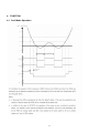
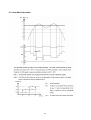
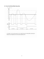
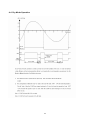
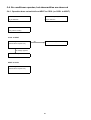
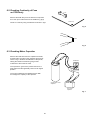
1
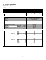
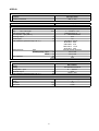
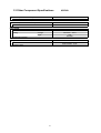
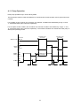
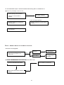
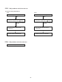
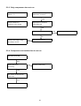
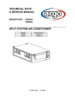
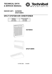
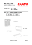
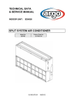
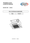
TECHNICAL DATA
& SERVICE MANUAL
INDOOR UNIT:
®
AS52AL
SPLIT SYSTEM AIR CONDITIONER
Model No.
AS52AL
Product Code No.
387006130
0.8180.416.0
07/2005
• Ground the unit following local electrical codes.
• The Yellow/Green wire cannot be used for any connection
different from the ground connection.
• Connect all wiring tightly. Loose wiring may cause overheating
at connection points and a possible fire hazard.
• Do not allow wiring to touch the refrigerant tubing, compressor,
or any moving parts of the fan.
• Do not use multi-core cable when wiring the power supply and
control lines. Use separate cables for each type of line.
IMPORTANT!
Please read before installation
This air conditioning system meets strict safety and operating
standards.
For the installer or service person, it is important to install or
service the system so that it operates safely and efficiently.
For safe installation and trouble-free operation, you must:
• Carefully read this instruction booklet before beginning.
• Follow each installation or repair step exactly as shown.
• Observe all local, state and national electrical codes.
• Pay close attention to all warning and caution notices given in
this manual.
•The unit must be supplied with a dedicated electrical line.
When transporting
Be careful when picking up and moving the indoor and outdoor
units. Get a partner to help, and bend your knees when lifting to
reduce strain on your back. Sharp edges or thin aluminium fins on
the air conditioner can cut your fingers.
WARNING
When installing...
This symbol refers to a hazard or unsafe practice which can result
in severe personal injury or death.
… In a ceiling
Make sure the ceiling is strong enough to hold the unit-weight.
It may be necessary to build a strong wooden or metal frame to
provide added support.
… In a room
CAUTION
Properly insulate any tubing run inside a room to prevent
"sweating", which can cause dripping and water damage to
walls and floors.
This symbol refers to a hazard or unsafe practice which can result
in personal injury or product or property damage.
... In moist or uneven locations
Use a raised concrete base to provide a solid level foundation
for the outdoor unit. This prevents damage and abnormal
vibrations.
If necessary, get help
These instructions are all you need for most installation sites and
maintenance conditions.
If you require help for a special problem, contact our sale/service
outlet or your certified dealer for additional instructions.
... In area with strong winds
Securely anchor the outdoor unit down with bolts and a metal
frame. Provide a suitable air baffle.
In case of improper installation
The manufacturer shall in no way be responsible for improper
installation or maintenance service, including failure to follow the
instructions in this document.
... In a snowy area (for heat pump-type systems)
Install the outdoor unit on a raised platform that is higher then
drifting snow. Provide snow vents.
SPECIAL PRECAUTIONS
When connecting refrigerant tubing
• During installation, connect before the refrigerant system and
then the wiring one; proceed in the reverse orden when removing
the units.
• Keep all tubing runs as short as possible.
• Use the flare method for connecting tubing.
• Apply refrigerant lubricant to the matching surfaces of the flare
and union tubes before connecting them; screw by hand and
then tighten the nut with a torque wrench for a leak-free
connection.
• Check carefully for leaks before starting the test run.
WARNING
When wiring
ELECTRICAL SHOCK CAN CAUSE SEVERE
PERSONAL INJURY OR DEATH. ONLY QUALIFIED,
EXPERIENCED ELECTRICIANS SHOULD ATTEMPT
TO WIRE THIS SYSTEM.
NOTE:
Depending on the system type, liquid and gas lines may be either
narrow or wide. Therefore, to avoid confusion, the refrigerant
tubing for your particular model is specified as narrow tube for
liquid, wide tube for gas.
• Do not supply power to the unit until all wiring and tubing are
completed or reconnected and checked, to ensure the grounding.
• Highly dangerous electrical voltages are used in this system.
Carefully refer to the wiring diagram and these instructions when
wiring.
Improper connections and inadequate grounding can cause
accidental injury and death.
When servicing
• Turn the power OFF at the main power board before opening
the unit to check or repair electrical parts and wiring.
• Keep your fingers and clothing away from any moving parts.
• Clean up the site after the work, remembering to check that no
metal scraps or bits of wiring have been left inside the unit being
serviced.
• Ventilate the room during the installation or testing the refrigeration
system; make sure that, after the installation, no gas leaks are
present, because this could produce toxic gas and dangerous
if in contact with flames or heat-sources.
2
Table of Contents
Page
4
4
5
6
1. SPECIFICATIONS
1-1 Unit specifications
1-2 Major Component specifications
1-3 Other Component specifications
2. DIMENSIONAL DATA
7
3. ELECTRICAL DATA
8
8
3-1 Electric Wiring Diagrams
9
9
10
11
12
13
13
15
18
18
18
19
4. FUNCTION
4-1 Cool Mode Operation
4-2 Heat Mode Operation
4-3 Auto Mode Operation
4-4 Dry Mode Operation
4-5 Fan Mode Operation
4-6 Protections in Cool/Dry Mode
4-7 Protections in Heat Mode
4-8 Sleep Function
4-9 Daily Timer
4-10 I FEEL Function
4-11 Drain Pump Operation
5. TROUBLESHOOTING
5-1 Check before and after troubleshooting
5-2 Air conditioner does not operate
5-3 Some part of air conditioner does not operate
5-4 Air conditioner operates, but abnormalities are observed
5-5 If a sensor is defective
6. CHECKING ELECTRICAL COMPONENTS
6-1 Measurement of Insulation Resistance
6-2 Checking Continuity of Fuse on PCB Ass'y
6-3 Checking Motor Capacitor
3
20
20
20
24
26
28
29
29
30
30
1. SPECIFICATIONS
1-1 Unit Specifications
AS52AL
Power source
220 - 240V ~ 50Hz
Voltage rating
230V
Performance
Capacity
Air circulation (High/Med./Low)
m³/h
Features
Controls/Temperature controls
Control unit
Timer
Fan speed
Airflow direction
Air Filter
Operation sound
Refrigerant tubing connections
Refrigerant
tube diameter
Refrigerant
Refrigerant tube kit / Air clean filter
Dimensions & Weight
Dimensions
Unit
Ceiling panel
Package dimensions
Unit
Ceiling panel
Weight
Unit
Ceiling panel
Vertical
High/Med./Low
dB-A
Narrow tube
Wide tube
mm(in.)
mm(in.)
Cooling
Heating
See catalogue with the requested matching
750/630/530
Microprocessor/ I.C. thermostat
Wireless remote control unit
ON/OFF 24 hours
3 and Auto /1(Hi)
Auto
Washable, Anti-Mold
53/48/45
Flare type
6,35 (1/4)
12,7 (1/2)
R410A
Optional / -------
273
mm
575
mm
575
mm
64
mm
730
mm
730
mm
380
mm
744
mm
650
mm
0,18
m3
110
mm
800
mm
800
mm
0,07
m3
18,2
kg
22,7
kg
2,50
kg
4,70
kg
DATA SUBJECT TO CHANGE WITHOUT NOTICE
Height
Width
Depth
Height
Width
Depth
Height
Width
Depth
Volume
Height
Width
Depth
Volume
Net
Shipping
Net
Shipping
4
AS52AL
Controller PCB
Part No.
Controls
Control circuit fuse
KSA
Microprocessor
250 V - 5 A
Remote Control Unit
RC-7 (RC)
Fan & Fan Motor
Type
Q'ty ……. Dia. and lenght
Fan motor model…Q'ty
No. Of poles…rpm (230 V)
Running Amps
Power input
Coil resistance (Ambient temp. 20 °C )
Safety devices
mm
A
W
Ω
Type
Operating temp. Open
Close
Run capacitor
Flap Motor
Type
Model
Rating
No of poles …rpm
Nominal output
Coil resistance (Ambient temp. 20 °C )
°C
°C
µF
VAC
W
kΩ
Heat Exch. Coil
Coil
Rows
Fin pitch
face area
Centrifugal fan
1…. Ø 280 / L 175
R4E280-AK45-12…1
4 … 890/750/650/280
0,33
75
BLU-BLK: 231,0
BLK-GRY: 50,2
GRY-RED: 27,8
RED-WHT: 119,5
WHT-BLU: 49,5
Internal thermal protector
160 ± 10K
130 ± 15K
2
450
Synchro motor
M2LJ24ZE31
AC 208/230V 50/60Hz
8 …. 2,5/3,0
3/2,5
16,45 ± 15%
Aluminium plate fin / Copper tube
2
1,3
mm
0,258
m2
DATA SUBJECT TO CHANGE WITHOUT NOTICE
5
1-3 Other Component Specifications
AS52AL
Thermistor ( Coil sensor TH1)
Resistance
ΚΩ
10 ± 3%
Thermistor ( Room sensor TH2)
Resistance
ΚΩ
10 ± 5%
Drain pump
Model
Rating
PC 309564003
220/240V - 50Hz
14W
0,4 l/min
Voltage
Input
Total head capacity
Safety float switch
Model
Contact rating
BI 1300 2725
230V AC/DC - 0,5A
6
2. DIMENSIONAL DATA
Units: mm
7
3. ELECTRICAL DATA
3-1 Electric Wiring Diagrams
8
4. FUNCTION
4-1 Cool Mode Operation
9
4-2 Heat Mode Operation
10
4-3 Auto (Cool/Heat) Mode Operation
11
4-4 Dry Mode Operation
12
4-5 Fan Mode Operation
4-6 Protection operations in Cool and Dry Mode
1. Indoor Coil Defrost Protection
5 Protection Operations in Cool and Dry Modes
13
2. Outdoor Coil High Pressure Protection
14
4-7 Protection Operations in Heat Mode
1. Outdoor Coil Deice Protection
15
16
2. Indoor Coil High Pressure Protection in Heat Mode
17
4-8 Sleep Function
4-9 Daily Timer Function
4-10 IFEEL Function
18
4-11 Pump Operation
Drain pump operates only in Cool and Dry Mode.
The float switch used for water level detection is closed under normal condition, and is open when wate
overflow.
For the NEC version of MCU, the "Overflow" and “Normal” conditions are indicated by a logic “0” and
“1” at the float switch pins connector respectively.
For the Fujitsu version of MCU, the "Overflow" and “Normal” condition are indicated by a logic “1” and
“0” at the float switch pins connector respectively. The overflow condition can activate the water pump in
Standy and operating modes
Overflow when
unit is ON
Overflow
Water Level
Overflow when
unit is OFF
Normal
ON
OPER
LED
COMP
(WVL)
OFF
BLINK
ON
COMP/WVL is
forced OFF
OFF
ON
PUMP
OFF
8 min
8 min
19
1 min
5.
6. TROUBLESHOOTING
5-1.
6-1. Check before and after troubleshooting
WARNING
Hazardous voltage can cause ELECTRIC SHOCK or
DEATH. Disconnect power or turn off circuit breaker
before you start checking or servicing.
6-1-1. Check power supply wiring.
5-1-1.
● Check that power supply wires are correctly connected to terminals L and N on the terminal plate in the indoor
unit.
6-1-2. Check inter-unit wiring.
5-1-2.
● Check that inter-unit wiring is correctly connected to the outdoor unit from the indoor unit.
6-1-3. Check power supply.
5-1-3.
● Check that voltage is in specified range (±10% of the rating).
● Check that power is being supplied.
6-1-4. Check lead wires and connectors in indoor and outdoor units.
5-1-4.
● Check that coating of lead wires is not damaged.
● Check that lead wires and connectors are firmly connected.
● Check that wiring is correct.
5-2. Air conditioner does not operate.
5-2-1. Circuit breaker trips (or fuse blows).
A. When the circuit breaker is set to ON, it trips immediately. (Resetting is not possible.)
● There is a possibility of ground fault.
● Check insulation resistance.
If resistance value is 2MΩ or less, insulation is defective (“NO”).
WARNING
* Set circuit breaker to OFF.
1
Remove inter-unit wires from
terminal plate in outdoor unit.
• Measure insulation resistance
of outdoor unit.
NO
Insulation of
outdoor unit
is defective.
• Measure insulation
resistance of electrical
parts in outdoor unit.
2
Remove inter-unit wires from
terminal plate in indoor unit.
Then, pull the power plug out of
the wall outlet
• Measure insulation resistance
of indoor unit.
NO
Insulation of
indoor unit
is defective.
20
• Measure insulation
resistance of electrical
parts in indoor unit.
B. Circuit breaker trips in several minutes after turning the air conditioner on.
● There is a possibility of short circuit.
• Check capacity of circuit breaker.
Replace with suitable
one (larger capacity).
NO
Capacity of circuit breaker is
suitable.
In case of Heating operation :
• Measure resistance of 4-way valve's
winding.
• Measure resistance of outdoor fan
motor winding.
• Measure resistance of compressor
motor winding.
5-2-2. Neither indoor nor outdoor unit runs.
5-2-2.
6-2-2.
A. Power is not supplied.
• Check power supply.
Circuit breaker
is tripped.
Reset breaker.
Power failure
Wait for recovery
or contact power
company.
NO
Power is being supplied to the
indoor unit.
B. Check
switch
Check "OPERATION
PUSH BUTTONselector"
in the indoor
unitin the indoor unit.
• OPERATION
selector
switch
is set
Press
the PUSH
BUTTON
switch
YES
Indoor PCB Ass'y is defective.
in ON position.
NO
Set OPERATION
selector
switch
Neither
the indoor nor
the outdoor
to ON.
units
run
21
C. Check remote control unit.
• Try to run with another remote
control unit.
OK
First remote control unit is defective.
• Check for residue buildup on
transmitter of remote control unit.
Clean transmitter.
• Check for residue buildup on remote
control receiver on front of indoor
unit.
Clean receiver.
D. Check fuse on the indoor PCB Ass'y.
• Check fuse on indoor PCB Ass'y
for continuity.
(F01)
If fuse has been blown,
Measure resistance of indoor and
outdoor fan motor winding.
(FM)
OK
OK
• Check operation lamp to see
if light is ON.
Measure resistance of compressor
motor winding.
(CM)
Light is OFF
OK
Measure resistance of 4-way valve's
windings
• Measure resistance of primary and
secondary winding of transformer.
(TR)
OK
OK
• Indoor PCB Ass'y is defective.
Replace the fuse.
E. Check TIMER on the remote control unit.
• Timer is turned ON. Check to see
if ON
or
is displayed on
remote control
YES
Cancel the timer mode.
22
6-2-3. Only outdoor unit does not run.
5-2-3.
A. Check setting temperature.
COOL
HEAT
Is room temperature too low ?
Is room temperature too high ?
NO
NO
Try to lower setting temperature by
temperature setting button ( button).
Try to raise setting temperature by
temperature setting button ( button).
Outdoor unit still does
not run.
Outdoor unit still does
not run.
• Try to run using another remote
control unit.
• Try to run using another remote
control unit.
OK
OK
Remote control unit is defective.
Remote control unit is defective.
6-2-4. Only Indoor unit does not run.
5-2-4.
• Indoor PCB Ass'y is defective.
23
5-3. Some part of air conditioner does not operate.
5-3-1. Only indoor fan does not run.
• Check fan rotation.
Turn fan gently once or twice by
hand.
• Check fan casing
foreign matter on
inside.
Fan cannot
be turned.
Fan motor burnout
or foreign matter in
bearings.
Remove foreign
matter or repair.
Repair or replace.
• Measure resistance of indoor fan
motor winding.
OK
• Check fan motor capacitor.
OK
PCB assy is defective.
5-3-2. Only flap motor does not run.
• Measure resistance of flap motor
winding.
5-3-2 Only outdoor fan does not run.
5-3-3.
• Check fan rotation.
Turn fan gently once or twice by
hand.
• Check fan casing
foreign matter on
inside.
Fan cannot
be turned.
Fan motor burnout
or foreign matter in
bearings.
• Measure resistance of outdoor fan
motor winding.
OK
• Check fan motor capacitor.
24
Remove foreign
matter or repair.
Repair or replace.
5-3-3. Only compressor does not run
Check compressor motor
Overload relay is working
capacitor C1
(either OLR T or OLR A)
YES
Measure resistance of
Temperature of compressor
compressor motor winding
is abnormally high
YES
Refrigerant gas shortage
NO
Measure power supply voltage
NO
Rotor may be locked up
The voltage is too low
5-3-4. Compressor and outdoor fan do not run
Float switch turned ON
YES
Check if drain pump
NO
Replace the drain pump
runs normaly
YES
Verify if drain condensate tube
is obstructed
YES
Remove obstruction
25
YES
Charge refrigerant gas
5-4. Air conditioner operates, but abnormalities are observed
5-4-1. Operation does not switch from HEAT to COOL (or COOL to HEAT)
Remote control unit
Receiver in lamp ass'y
may be defective
may be defective
Measure resistance of
4-way valve's winding
COOL to HEAT
Check voltage between
terminals N and 6 (230V AC)
OK
Outdoor PCB ass'y is defective
No voltage appears
Indoor PCB ass'y is defective
HEAT to COOL
Check voltage between
terminals N and 6 (230V AC)
26
6-4-2. Poor cooling or heating.
5-4-2.
• Check position of remote control unit.
• Cool or warm air from air conditioner
reaches position directly.
YES
Change position of remote
control unit.
• Wide and narrow tubes between
indoor unit and outdoor unit are
insulated.
NO
Insulate both wide and narrow
tubes separately and then
tape together.
(only with I FEEL feature selected)
YES
• Measure temperature of suction and
discharge air of air conditioner.
Temperature
difference
is small.
Possibility of
gas shortage.
Charge refrigerant
gas.
Temperature difference between
suction and discharge air is
large enough (approx. 10 deg. or more).
Check for clogging of air filter.
Clean filter.
Air filter is clogged.
• Fan speed is set to LOW.
YES
Set fan speed to either
HIGH or MEDIUM.
Reduce cooling or heating
load or replace the air
conditioner with larger
capacity.
• Review cooling load estimate,
if performance of air conditioner is
normal.
6-4-3. Excessive cooling or heating.
5-4-3.
• Set temperature is suitable.
• Remote control unit is placed where
it can detect room temperature
properly.
Set temperature to higher or
lower value using temperature
setting buttons of the remote
control unit.
NO
NO
Change position of remote
control unit.
27
6-5 If a sensor is defective
6-5-1 ICT (indoor coil sensor) OCT(outdoor coil sensor) RAT (room ambient temperature) are defective.
•
Stand by lamp on front side of indoor
unit is flashing on and off. (*)
YES
•
Thermistor ICT and OCT and RAT are
defective
YES
•
Repalce thermistor.
NOTE Allarm signal (*)
Stan by lampoon on the front side of the indoor unit will flash on and off when the thermistor is defective.
At the same time the outdoor unit will stop. Indoor operate only for ventilation.
Temperature sensor
Lead wires
28
6. CHECKING ELECTRICAL COMPONENTS
6-1 Measurement of Insulation
Resistance
power plug
(Local supply)
Ground
The insulation is in good condition if the
resistance exceeds 2MΩ
probe
Insulation
tester
NOTE
6-1-1. Power supply wires
The shape of the power plug may differ from that
of the air conditioner which you are servicing.
Clamp the grounding terminal of the power plug
with a lead clip of the insulation resistance tester
and measure the resistance by placing a probe
on both the two power terminals. (fig.1)
Fig. 1
Terminal plate
Then, also measure the resistance between the
grounding and other power terminals. (fig.1)
Probe
6-1-2. Indoor Unit
Clamp a metallic part of the unit with the lead
clip of the insulation resistance tester and measure
the resistance by placing a probe on each terminal
screw where power supply lines are connected on the
terminal plate. (fig.2)
Clip
Copper
tube or
metallic part
Insulation
tester
Fig. 2
6-1-3. Outdoor Unit
Clamp an aluminium plate fin or copper tube with
the lead clip of the insulation resistance tester
and measure the resistance by placing a probe
on each terminal screw on the terminal plate. (fig.2)
Note that the ground line terminal should be skipped
for the check.
Probe
Clip
Copper
tube or
metallic part
6-1-4. Measurement of Insulation
Insulation
tester
Resistance for Electrical Parts
Disconnect the lead wires of the desired electric
part from terminal plate, capacitor, etc.
Similary disconnect the connector.
Then measure the insulation resistance. (fig.3 and 4)
From fan motor,
compressor and
other parts
Metallic
part
NOTE: Refer to electric wiring diagram
Fig. 3
Probe
Clip
If the probe cannot enter the poles because the
hole is too narrow then use a probe with a
thinner pin.
Insulation
tester
Fig. 4
29
6-2 Checking Continuity of Fuse
on PCB Ass'y
Fuse
Remove the PCB Ass'y from the electrical component
box. Then pull out the fuse from the PCB Ass'y. (fig.5)
PCB Ass’y
Check for continuity using a multimeter as shown in fig.6
Fig. 5
Fuse
Fig. 6
6-3 Checking Motor Capacitor
Remove the lead wires from the capacitor terminals,
and then place a probe on the capacitor terminals as
shown in fig.7. Observe the deflection of the pointer,
setting the resistance measuring range of the
multimeter to the maximum value.
Multimeter
The capacitor is "good" if the pointer bounces to a
great extent and then gradually returns to its original
position.
The range of deflection and deflection time differ
according to the capacity of the capacitor.
Compressor motor
capacitor
Fan motor
capacitor
Fig. 7
30
Via Varese, 90 - 21013 Gallarate - Va - Italy
Tel. +39 0331 755111 - Fax +39 0331 776240
www.argoclima.it