1
CRR FT$1VlRW
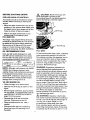
3.5 Horsepower
9 Inch
EDGER
MODEL NO.
536.797460
Caution:
Read and follow all Safety
Rules and Operating
Instructions before first use
of this product.
SEARS, ROEBUCK
337726
3125/96
AND CO., Hoffman Estates 60179 U.S.A.
Table of Contents
Warranty
Safety Rules
Contents of Shipping Carton
Assembly
Operation
Maintenance
LIMITED
ONE-YEAR
2
2
2-3
4
4-6
7-10
10-12
Service and Adjustments
Storage
Troubleshooting
Edger Repair Parts
Engine Repair Parts
Spanish(EspaRol)
Parts Ordering/Service
WARRANTY
ON CRAFTSMAN
12-13
13-14
14
15-17
18-21
22-35
Back Cover
EDGER
For one year from the date of purchase, when this Craftsman Edger is maintained, lubricated, and tuned up according to the operating and maintenance instructions in the
owner's manual, Sears will repair, free of charge, any defect in material or workmanship.
ff this Craftsman Edger is used for commercial or rental purposes, this warranty applies for only 90 days from the date of purchase.
This warranty does not cover the following:
• Expendable items which become worn during normal use, such as spark plugs, etc.
• Repairs necessary because of operator abuse or negligence, including bent crank
shafts and the failure to maintain the equipment according to the instructions contained in the owner's manual.
WARRANTY SERVICE IS AVAILABLE BY RETURNING THE CRAFTSMAN EDGER
TO THE NEAREST SEARS SERVICE CENTER/DEPARTMENT
IN THE UNITED
STATES. THIS WARRANTY APPLIES ONLY WHILE THIS PRODUCT IS IN USE IN
THE UNITED STATES.
This warranty gives you specific legal rights, and you may also have other rights which
may vary from state to state.
Sears, Roebuck and Co., D817WA, Hoffman Estates, IL 60179
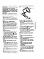
A_
Look for this symbol to point out Important safety precautions.
ATTENTION!!!
Become alert!!! Your safety is involved.
/_
CAUTION: Always disconnect spark
plug wire and place wire where it cannot
contact spark plug to prevent accidental
starting when setting-up, transporting,
adjusting or making repairs.
IMPORTANT: Safety standards require
operator presence controls to minimize the
risk of injury. Your edger is equipped with
such controls. Do not attempt to defeat the
function of the operator presence control
under any circumstances.
BEFORE
USE
• Read the owner's manual carefully. Be
thoroughly familiar with the controls and
the proper use of the edger. Know how to
stop the edger and disengage the
controls quickly.
• Do not operate the edger without
wearing adequate outer garments. Wear
It means---
footwear that will improve footing on
slippery surfaces.
• Keep the area of operation clear of all
persons, particularly small children and
pets.
• Thoroughly inspect the area where the
edger is to be used and remove all
foreign objects.
FUEL SAFETY
• Handle fuel with care; it is highly flammable.
• Use an appro'_ed container.
• Check fuel supply before each use,
allowing space for expansion as the heat
of the engine and/or sun can cause fuel to
expand.
• Fill fuel tank outdoors with extreme care.
Never fill fuel tank indoors. Replace fuel
tank cap securely and wipe up spilled
fuel.
• Never remove the fuel tank cap or add
fuel to a running or hot engine.
• Never store fuel or edger with fuel in the
tank inside a building where fumes may
reach an open flame.
OPERATING
SAFETY
• Never allow children or young teenagers
to operate the edger. Keep them away
while it is operating. Never allow adults to
operate the edger without proper instruction.
• Do not operate this machine if you are
taking drugs or other medication which
can cause drowsiness or affect your
ability to operate this machine.
• Do not use this machine if you are
mentally or physically unable to operate
this machine safely.
• Always wear safety glasses or eye
shields during operation or while performing an adjustment or repair to protect
your eyes from foreign objects that may
be thrown from the edger.
• Do not put hands or feet near or under
rotating parts.
• Exercise extreme caution when operating
on or crossing gravel drives, walks, or
roads. Stay alert for hidden hazards or
traffic.
• Exercise caution to avoid slipping or
falling.
• Never operate the edger without proper
guards, plates, or other safety protective
devices in place.
• Never operate the edger at high transport
speeds on slippery surfaces. Look behind
and use care when backing.
• Never allow bystanders near the edger.
• Keep children and pets away while
operating.
• Never operate the edger without good
visibility or light.
• Do not run the engine indoors. The
exhaust fumes are dangerous, containing
CARBON MONOXIDE, an ODORLESS
and DEADLY GAS.
• Take all possible precautions when
leaving the edger unattended. Stop the
engine.
• Do not overload the edger capacity by
attempting to edge too deep at too fast a
rate.
SAFE STORAGE
'
• Always refer to the owner's manual
instructions for important details if the
edger is to be stored for an extended
period.
• Never store the edger with fuel in the fuel
tank inside a building where ignition
sources are present such as water and
space heaters, clothes dryers, and the
like. Allow the engine to cool before
storing in any enclosure.
• Keep the edger in safe working condition.
Check all fasteners at frequent intervals
for proper tightness.
REPAIR/ADJUSTMENTS
SAFETY
• After striking a foreign object, stopthe
engine (motor). Remove the wire from the
spark plug, and keep the wire away from
the plug to prevent accidental starting.
Thoroughly inspect the edger for any
damage, and repair the damage before
restarting and operating it.
• If edger should start to vibrate abnormally,
stop engine (motor) and check immediately for the cause. Vibration is generally
a warning of trouble.
• Stop the blade whenever you leave the
operating position. Also, disconnect the
spark plug wire before unclogging the
blade and when making any repairs,
adjustments, or inspections.
• When cleaning, repairing, or inspecting,
shut off the engine and make certain all
moving parts have stopped.
• Never attempt to make any adjustments
while the engine is running except when
specifically recommended by the manufacturer.
Z_ WARNING:
The engine exhaust
from this product contains chemicals
known to the State of California to cause
cancer, birth defects or other reproductive
harm.
L_
WARNING:
This unit is equipped with
an internal combustion engine and should
not be used on or near any unimproved forest-covered, brush-covered or grass-covered land unless the engine's exhaust system is equipped with a spark arrester meeting applicable local or state laws (if any). If a
spark arrester is used, it should be maintained in effe(_tive working order by the operator.
In the state of California the spark arrester is
required by law (Section 4442 of the California Public Resources Code). Other states
may have similar laws. Federal laws apply
on federal lands. A spark arrester/muffler is
available through your nearest Sears Authorized Service Center (See ENGINE REPAIR
PARTS section in this manual).
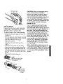
Contents of Parts Bag (shown full size)
(2)- Hex Head Screws
5/16-18x 1-1/4 inch
(2) - Hex Head Nuts
5/16-18
(2) - Flatwashers(large)
(2) - Flatwashers(small)
,520xl .25x.209
.504x.75x.059
(2) - Hair Pins
(3) - Retaining Rings
(1 is a spare)
Parts packed separately in carton (not shown full size)
(1)-Control
Rod
1 - Container SAE30 oil
(2) - Tire & Rims
1 - Owner's Manual (not shown)
1 - Parts Bag (not shown)
,4k
Z.L_CAUTION:
Always wear safety
glasses or eye shields while assembling
edger.
TOOLS
REQUIRED
Control Lever
Handle
FOR ASSEMBLY
Lever
1 - 7/16 inch Wrench
(or adjustable wrench)
Handle
2 - 1/2 inch Wrenches
(or adjustable wrenches)
1 - Pair Pliers
1 - Knife
The figure to the right shows the edger
completely assembled.
References to the right or left hand side
of the edger are from the viewpoint of the
operator's position behind the unit.
Handle
Blade
tard
TO REMOVE
EDGER
FROM
CARTON
• Remove the control rod from the carton,
• Remove wheels, parts bag and packing
material from the carton.
• Cut down all four corners of the carton.
TO ASSEMBLE
THE
EDGER
• Pivot the upper handle upward being
careful not to pinch or pull the engine
control wire, until the mounting holes in
the upper handle align with the mounting
holes in the lower handle. Install (2) 5/1618 x 1-1/4 inch hex head screws and (2)
5/16-18 hex lock nuts (found in parts
bag) in the empty handle holes and
tighten all four clamping bolts. Locknuts
should be to the inside of the handles as
• Insert one end of the control rod from right
to left through the hole in the depth
control lever and attach with a hair pin
found in parts bag. See figure below.
• Place the depth control lever in the rear
selection slot and insert the lower end of
the control rod through the hole in the
pivot bracket arm located inside the frame
on the rear axle. Attach with hairpin.
Rear
Selection,
Con_ol
Rod
Hair Pin
shown in figure below.
Lower
Handle
5/16-18
Hex
Locknuts
5/16-18X1-1/4 inch
Hex Head wide
flange Screws
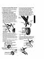
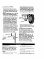
• Attach left rear wheel to the edger as
shown below. Place two large flatwashers
(need to keep wheel away from side
frame bolts) between the wheel and the
frame. Place one small flatwasher outside
of the wheel and install the retaining ring
on the axle.
• Attach right rear wheel as shown below to
the edger. Place a flatwasher and
retaining ring to rear axle.
VIEW FROM LEFT REAR WHEEL
Flatwasher (large)
.520x 1.25x.209
Flatwasher(small)
,504x.75x.059
g Ring
520xl .25x
VIEW FROM RIGHT REAR WHEEL
Flatwasher(small)
.504x.7!
Retaining
Hair Pin
Pivot
Arm
Rod
• Loosen the rope guide nut located on the
inside of the right handle as shown below.
• Thread starter rope through the guide.
• Tighten nut.
Starter
Nut
Rope
/'
CHECKLIST
,/
All fasteners have been properly
stalled and tightened.
While learning how to use your edger,
pay extra attention to the following
important items:
Before you operate your new Edger, to
ensure that you receive the best performance and satisfaction from this quality
product, please review the following
checklist:
/
All assembly
completed.
/
No remaining loose parts in carton, except spare retaining ring. Keep in safe
place.
instructions
in-
,#/
Engine oil is at proper level.
,//
Fuel tank is filled with fresh, clean,
regular Unleaded gasoline.
//
Become familiar with all controls, their
location and function. Operate controls
before starting engine.
have been
KNOW YOUR EDGER
READ THIS OWNER'S
MANUAL AND SAFETY RULES BEFORE OPERATING
YOUR
EDGER. Compare the illustrations with your EDGER to familiarize yourself with the location
of various controls and adjustments. Save this manual for future reference.
•
Fast
Slow
I+
Stop
Primer Button
Engine Control
Throttle
Contro_Rod
3ap
Blade Guard
Blade Guide
Throttle Control - Used to control the engine speed.
Primer Button - Injects fuel directly into the
carburetor manifold for faster starts.
when cleaning, replacing or inspecting the
edger.
Engine Control
Lever
Starter Handle - The engine On this edger
is equipped with an easy pull recoil starter.
Depth Control Lever - Controls the depth
of the blade.
Blade Guard - Used to prevent stones or
other material from being thrown at the operator.
Engine control Lever - Must be held back
to allow engine to start and run.
L_
WARNING:
Blade is rotating when
engine is running or being started. Keep
hands and feet away from blade to prevent
injury.
HOW TO USE YOUR EDGER
L_
WARNING:
The operation of this
edger can result in foreign objects being
thrown into the eyes, which can cause severe eye damage. Always wear safety
glasses or eye shields while operating the
edger.
We recommend standard safety glasses or
Wide Vision Safety Mask for over your
glasses.
TO STOP EDGER
• Make sure the depth control lever is all
the way forward and releaseengine
control lever to the STOP _
position.
Wait for all moving parts to stop before
leaving the operator position.
L_
CAUTION:
Never leave the edger
unattended while the engine is running.
Always raise the cutting blade and stop the
engine.
TO USE THE
LEVER
ENGINE
CONTROL
• Pull the engine control lever back with
your left hand and hold it in contact with
the upper handle cross tube to allow engine to start and run. See next figure.
TO USE THROTTLE
• Run at full'_
engine speed during
normal use.
• Push throttle control lever forward to
increase speed; beck to decrease
speed.
• Pulling the throttle control lever all of the
way back will stop _
the engine.
TO USE PRIMER BUTTON
|.1
• Push primer button r"_ five times. See
page 6 figure for location. Wait about two
seconds between each push.
NOTE: Do not use primer button to restart a warm engine after a short shutdown.
TO USE THE DEPTH CONTROL
LEVER
• Position your edger in desired edging location, before operating.
• Start the engine and move the depth
control lever back to lower the cutting
blade.
• Select the edging depth you need.
There are 4 selections up to 2-1/2
inches deep.
IMPORTANT:
• Release the engine control lever to stop
the engine.
an,
Ln__ CAUTION:
Always stop
engine
make sure all parts have stopped
whenever leaving the operator's position or
If very deep edging is
required, we recommend that a shallow
cut be made first, then cuts at greater
depths until the desired depth is obtained.
NOTE: If engine continues to run after lever is released, see your Sears service
center.
the
CONTROL
L_
WARNING:
Keep away from the ro-
tating blade. The blade can cause injury.
BEFORE STARTING
PRE-USECHECK
ENGINE
OFCONTROLS
All controls should be checked for proper
function before servicing or starting the
engine.
,l_
CAUTION:
Never fill the gas tank
while the engine is running or hot.
Immediately wipe off any spilled gasoline
before attempting to start the engine.
• Move the depth control lever into all four
positions in the selector plate. Make sure
the depth control lever snaps into all four
holes as shown in figure on page 6.
Fill Cap
• Return the depth control lever to the
forward hole in the selector plate.
FILL/ADD
OIL:
This edger was shipped with a 20 ounce
container of SAE30 motor oil. This oil must
be added to the engine before operating.
Remove the oil fill cap and fill the crankcase to 1/4 inch from top of oil fill hole,
residual oil remaining. DO NOT OVERFILL.
-Fuel Fill Cap
FILL GAS:
OIL RECOMMENDATIONS
the oil's SAE viscosity grade according to
your expected operating temperature:
Fill the fuel tank with clean, fresh, unleaded
grade automotive gasoline. Be sure that
the container you pour the gasoline from is
clean and free from dust or other foreign
particles. Never use gasoline that may be
stale from long periods of storage in the
I,, Coldersw30"
container.
Only use high quality detergent oil rated
with API service classification SG. Select
NOTE:
32°F
>_Warmer-- '>
_ _ -'_--A_30
Although multi-viscosity
oils (5W30,
10W30, etc.) improve starting in cold
weather, these multi-viscosity oils will result
in increased oil consumption when used
above 32°F. Check your engine oil level
more frequently to avoid possible engine
damage from running low on oil.
TO ADD ENGINE OIL
• Place the edger on a level surface.
• Remove the oil fill cap as shown in next
figure.
• Fill the engine crankcase, pouring slowly.
Do not overfill. For approximate capacity
sea PRODUCT SPECIFICATIONS
on
page 10 of this manual.
• Reinstall the oil fill cap and tighten
securely. Wipe away excess oil.
• Check oil before each use. Add if
needed.
• Change oil after the first 2 operating
hours and every 25 operating hours
thereafter.
WARNING:
Reinstall fuel cap.
Experience
indicates that
alcohol blended fuels (called gasohol or
using methanol) can attract moisture which
leads to separation and formation of acids
during storage. Acidic gas can damage the
fuel system of an engine while in storage.
To avoid engine problems, the fuel system
should be emptied before storage of 30
days or longer. Drain fuel tank, start engine
and let it run until fuel lines and carburetor
are empty. Use fresh fuel next season. See
Storage Instructions for additional information. Never use engine or carburetor
cleaner products in the fuel tank or permanent damage may occur.
"_
WARNING:
Gasoline
is flammable
and caution must be used when handling or
storing it. Do not fill fuel tank while Edger is
running, hot, or when Edger is in an
enclosed area. Keep away from open
flame, electrical spark, and do not smoke
while filling the fuel tank. Never fill fuel tank
completely; but fill the tank to within 1/4-1/2
inch from the top to provide space for
NOTE: The cutting blade speed is
controlled by the engine speed. To
reduce the cutting blade speed, push
back on the throttle control lever. To
expansion of fuel. Always fill fuel tank
outdoors and use a funnel or spout to
prevent spilling. Make sure to wipe up any
spilled fuel before starting the engine. Store
gasoline in a clean, approved container,
and keep the cap in place on the container.
Keep gasoline in a cool, well ventilated
place; never in the house. Never buy more
than a 30 day supply of gasoline to ensure
volatility. Gasoline is intended to be used as
a fuel for internal combustion engines;
therefore, do not use gasoline for any other
purpose. Since many children like the smell
of gasoline, keep it out of their reach
because the fumes are dangerous to inhale,
as well as being explosive.
TO START THE ENGINE
Before starting the engine, be sure you
have read and understood all the instructions on the preceding pages. The edger is
equipped with a recoil starter. The operation of the engine is controlled by the
throttle control lever. See page 6.
• Push the depth control lever forward and
latch in the forward slot of the adjustment
bracket to raise the blade.
• Move the throttle control lever, see figure
on page 6, to the FAST '_
position.
• Push primer button I_-
five times, see
I/
figure on page 6. wait about two
seconds between each push.
NOTE:
Do not use primer to restart a
warm engine after a short shutdown.
• Pull the engine control lever back to
contact the upper handle tube and hold
the edger handle and control lever firmly
with your left hand.
• Tostart engine, grasp the engine starter
handle firmly with your right hand.
• Pull back sharply on the recoil starter
handle. DO NOT allow the starter rope to
snap back, let it rewind slowly while
holding the starter handle.
NOTE:
If engine fails to start after three
pulls, push primer button two times and
pull starter rope again.
• When the engine starts, run at fult engine
speed during normal use.
increase the blade speed, push the
throttle control lever forward.
• To stop IO
the engine, make sure the
depth control lever is all the way forward
and release the engine control lever to
the stop position. See figure on page 6.
Z_
WARNING:
Never run the engine
indoors or in a poorly ventilated area.
Engine exhaust contains carbon monoxide,
an odorless gas and deadly gas. Keep
hands, feet, hair and loose clothing away
from any moving parts on the engine or
edger. Avoid the muffler and surrounding
areas. Temperatures may exceed 150' F.
EDGING TIPS
• Edging is best performed when conditions
are dry. if the soil is too wet, dirt becomes
packed in and around the blade causing
premature belt wear and decreased
performance.
• If dirt does become packed around the
blade, stop the engine, remove the spark
plug wire, and remove the packed debris
before continuing to edge.
• ff very deep edging is required, we
recommend that a shallow cut be made
first, then cuts at greater depth until the
desired depth is obtained.
• Uniform edging can be performed when
the blade guide (see figure on page 6)
rides on and against the surface which
you are edging.
• Edging can be customized by varying the
number of passes and by the distance
your blade is from the surface you are
edging.
CUSTOMER
RESPONSIBILITIES
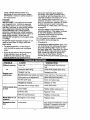
SCHEDULE
SERVICE
RECORDS
Fill In dates as
you complete
regular service
SERVICE
DATES
After
Before Fie.
E_en/ Every Every Begin
Before
First
Each quently
10
25
_Each
Storaga
2
Use
Hours
Hours
Hours
Season
Hours
Lubricateall Pivot Points
tJ
LubricateWheel Axles
Ivj
tJ
Check Engine Oil Level
Change Engine Oil
tJ
tf
_
tJ
t,J
!Replace Air Cleaner Filter
Check Spark Plug
p,_
Check Drive Belt
T_ghtenAll Screws and Nuts
jvj
Check Blade Wear/Damage
PRODUCT
_'_
V 'l
SPECIFICATIONS
HORSEPOWER:
3.5
NOTE: If the edger is being used in sandy
or dusty areas, change the oil more frequently to prevent premature engine wear.
DISPLACEMENT:
9.06 cu. in. (148 cc)
TO CHANGE
GASOLINE
CAPACITY:
LUBRICATION:
SPARK PLUG:
(Gap .030)
GENERAL
ENGINE OIL
• Disconnect the spark plug wire from the
spark plug.
1.25 qt.
(unleaded regular)
• Remove the oil drain plug as shown below and drain the oil into a flat pan.
20 oz. SAE-30W
• After draining all the oil, reinstall the oil
drain plug securely.
Champion RJ19LM
or Equivalent
NOTE: The oil will drain more freely when
the engine is warm.
RECOMMENDATIONS
• Remove the oil fill cap. See figure on
page 8.
The warranty on this Edger does not cover
items that have been subjected to operator
abuse or negligence. To receive full value
from the warranty, the operator must maintain the Edger as instructed in this manual.
The above chart is provided to assist the
operator in properly maintaining the Edger.
• Fill the engine crankcase, pouring slowly.
DO NOT OVERFILL. For approximate capacity see PRODUCT SPECIFICATIONS.
NOTE: The quill assembly bearings are
factory sealed and will require no lubrication.
o
LUBRICATION
• After each 25 hours of use of your Edger,
apply light machine oil to all moving
parts, particularly the wheels.
• Reconnect the spark plug wire on the
spark plug.
• The oil in the engine crankcase must be
changed after the first 2 hours of operation and after each 25 hours of use thereafter.
10
Oil Drain Plug
CAUTION:
Never run the engine without
the air cleaner element installed. A
defective air cleaner can result in loss of
engine power and can cause excessive
wear or damage to the engine components
if dirt or dust is permitted to enter the
engine through the carburetor. A damaged
air cleaner, or one that is clogged with dust
or dirt should be replaced immediately.
SPARK
AIR CLEANER
Replace the filter once a year; more often
under dusty or dirty conditions. DO NOT
attempt to c_ean or oil the air filter.
To install a new air filter, do the following:
• Disconnect
the spark plug wire from the
spark plug.
• Turn the cover as shown below to the left
(counterclockwise)
and remove the cover
and the air filter from the flange.
• Discard the air filter.
• Clean the cover and the flange thoroughly.
• Insert the new air filter into the cover.
• Push the cover firmly
and turn it to the right
as it will go as shown
sure the retainers are
against the flange
(clockwise) as far
in figure below. Be
locked around the
flange.
• Reconnect
"_
the spark plug wire.
_Turn
cover to the left
_"_==,.J _[ (counterclockwise)
v to remove
F_ange
Iter
Slot
Tab
cover
to the right
(clockwise)
to install
PLUG
Clean the spark plug and reset the gap
periodically. Clean the area around the
spark plug base before removal, to prevent
dirt from entering the engine. Replace the
spark plug if the electrodes are pitted or
burned or if the porcelain is cracked. Clean
the spark plug by carefully scraping the
electrodes (do not sand blast or use a wire
brush). Be sure the spark plug is clean and
free of foreign material. Check the electrodes gap with a wire feeler gauge and
reset to .030 if necessary. If a new spark
plug is needed, refer to the PRODUCT
SPECIFICATIONS
for the proper replacement spark plug.
Before reinstalling the spark plug, coat the
threads lightly with graphite or light oil to
insure easy removal. Tighten the spark plug
firmly into the engine. If a torque wrench is
available, torque the spark plug to 15 footpounds.
BLADE REPLACEMENT
,_
CAUTION:
Always stop the engine
and disconnect the spark plug wire before
making any repairs to the edger.
The cutting blade is subject to wear and
damage such as nicks and dents. This will
not generally affect its function.
V-BELT REPLACEMENT
This blade is specially designed to not require sharpening. Do not attempt to sharpen
this blade. If worn or damaged the blade
should be replaced.
Your edger is equipped with a V-belt made
of a special compound. If the belt becomes
worn or breaks, replace it with an orignal
equipment belt as shown in the Repair
Parts section of this manual. Never use a
substitute.
CAUTION:
When removing or tightening
the blade nut, always use the method
shown in figure below. The holding wrench
must always be positioned on the nut behind the cutting blade.
• Disconnect the spark plug wire.
• Drain gasoline and oil from edger.
• Tip edger backwards on handle and
block top of handle against wall or bench.
• Remove three screws and flatwashers
,_
CAUTION:
Do not attempt to sharpen
this blade. You could cause damage to the
blade which could result in breakage and
possible user or bystander injury.
from the belt guard as shown in figure
below.
To replace the blade, do the following:
• Disconnect spark plug wire.
• Remove the 1/2-20 Iocknut shown in
figure below securing the blade to the
drive shaft.
• Remove the blade.
IMPORTANT:
Note the position of the
washer and the blade cutting edge to
ensure proper re-assembly. The blade is
marked THIS SIDE OUT.
• Position the replacement blade against
the washer on the drive shaft and secure
with flange nut. Be sure to tighten nut
securely.
• Reconnect the spark plug wire.
p.Bearing
Housing
Tightening
Wrench
twist
• Push blade bearing housing back towards
engine to compress spring and release
tension on belt.
• Remove old belt (carefully note direction
of twist around engine pulley).
• While spring is compressed, install new
belt on quill and engine pulleys being sure
to twist belt in proper direction as shown
in figure.
Holdin_
NOTE: If belt is not installed properly the
blade will not turn in the proper direction and
could damage the blade or bolt. Refer to
figure above for proper direction of belt
travel.
_2
LEVELING
raise the blade and out (countemlockwise) to lower the blade. The adjustment
is correct when there is a 1/4 inch space
between the edging guide and the bench
top. When the rod is adjusted correctly,
insert the hook of the rod into the hole in
the linkage bracket and replace the
hairpin cotter in the hole in the hook.
ADJUSTMENT
• When the depth control lever is in the
forward adjustment slot, the engine
platform should be approximately level
and the edging blade tip should be 1-1/4
to 1-1/2 inches above the surface of the
ground.
• When the depth control lever is in the rear
adjustment slot the edging guide (see
figure below) should be approximately 1/4
inch above the surface which you
are edging and the blade tip should be
2-5/8 to 2-7/8 inches below the surface of
the ground. The two middle adjustment
slots provide shallower edging depths.
Lower
Rod
• To adjust the depth control lever to give
the proper blade proper blade positions,
remove the ignition wire from the spark
plug and keep the wire away from the
spark plug. Place the edger on a work
bench or sturdy table. Position edger so
that the blade can extend below the top of
the bench top, put the depth control lever
in the rear adjustment slot and place a
1/4 inch thick shim between the edging
guide and the top of the bench, see figure
below. Remove the hairpin cotter from the
hook in the lower control rod and slide the
hook out of the hole in the linkage
bracket. Turn the rod in (clockwise) to
• When the adjustment procedure is
complete, put the edgar back on the floor
and install the _jnition wire on the spark
plug.
CARBURETOR
ADJUSTMENT
The carburetor has been pre-set at the
factory and readjustment should not be
necessary. However, if the carburetor does
need to be adjusted, contact your nearest
Sears Service Center.
Edging Guide--
IMPORTANT:
Never tamper with the
engine governor, which is factory set for
proper, engine speed. Overspeeding the
engine above the factory high speed
setting can be dangerous. H you think the
engine-governed high speed needs
adjusting, contact your nearest Sears
Service Center, which has the proper
Table
-Blade
1/4 inch
Space
equipment and experience to make any
necessary adjustments.
,/_
WARNING:
• Inspect the edger for worn or damaged
parts and*tighten all loose hardware.
Never store your
edger indoors or in an enclosed, poody
ventilated area. If gasoline remains in the
tank, fumes may reach an open flame,
spark or pilot light from a furnace, water
heater, clothes dryer, cigarette, etc.
• Oil all points described in the Lubrication
paragraph in the MAINTENANCE section
of this manual.
• Store the edger in a protected area and
cover for additional protection.
EDGER
• Clean the edger thoroughly; remove all
debris and wipe the unit dry.
IMPORTANT:A
13
yearly checkup or tune-
up by a Sears Service Center is a
good way of ensuring that your Edger
will Provide maximum performance for
the next season.
the tank to minimize gum deposits
and acids. If the tank is almost empty,
mix stabilizer with fresh gasoline in a
separate container and add some to the
tank. Always follow instructions on
stabilizer container. Then run engine at
least 10 minutes after stabilizer is added
to allow mixture to reach carburetor.
Store edger in a safe place. See warning
on page 13.
ENGINE
IMPORTANT:
It is important to prevent
gum deposits from forming in essential
fuel system parts such as the carburetor,
fuel filter, fuel hose, or tank during storage.
Also, experience indicates that using
alcohol-blended fuels (called gasohol,
ethanol or methanol) can attract moisture
which leads to separation and formation of
acids during storage. Acidic gas can
damage the fuel system of an engine while
in storage.
• Store the edger in the wheels-down,
operating position. If the edger is stored
in any other position, oil from the
crankcase could enter the cylinder,
causing a service problem.
You can keep your engine in good operating condition during storage by:
To prevent engine damage (if edger is not
used for more than 30 days) follow the
steps below.
• Changing oil.
• Lubricating the piston/cylinder area. This
can be done by first removing the spark
plug and squirting clean engine oil into
the spark plug hole. Then cover the spark
plug hole with a rag to absorb oil spray.
Next, rotate the engine by pulling the
starter two or three times. Finally,
reinstall spark plug and attach spark plug
wire.
• To remove gasoline, run the engine
until the tank is empty and the engine
stops.
• If you do not want to remove gasoline,
a fuel stabilizer (such as Sears
Craftsman fuel stabilizer No. 33500)
may be added to any gasoline left in
TROUBLE
CAUSE
Difficult starting
CORRECTION
Stale fuel
Drain fuel tank. Fill with fresh
fuel
Defective spark plug
Clean and re-gap spark plug
Clogged fuel line
Replace fuel filter
Blocked fuel line or empty fuel tank
Clean fuel line; check gas tank
Carburetor out of adjustment
Have carburetor adjusted
Fouled spark plug
Clean and adjust gap
Clogged air cleaner
Replace air filter
Jammed due to foreign object
Clear obstruction
Loose blade
Tighten blade retaining nut
Defective belt
Replace V-belt
Defective quill bearings
RepTace the bearings
Blade falls to cut
properly
Damaged or worn blade
Replace blade
Excessive
tlon
Loose parts
Stop engine immediately; tighten
all bolts. If vibration continues,
take the unit into the nearest
Sears Service Center
or
Engine runs
erractlcally
Cutting blade falls
to turn
vibra-
14
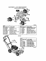
CRAFTSMAN 9" - 3.5 H.P. EDGER 536.797460
ENGINE/FRAME ASSEMBLY
@
@
@
Note: Always use original equipment
parts. Use of service/replacement
partsother than original parts may void
your warranty.
All unnumbered
interchangeable
side
items ere
with opposite
339589A
REF.
NO. PART NO.
10
ENGINE
12
2O
22
100
300
301
302
305
310
311
48148
52052
102580
337658-833
339283
51603
412281
32668
336555
57072
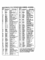
REF,
PART NAME
NO.
PART NO.
3.5 HP 143.963508
(See Engine pages)
Screw, 3/8-16 x 1.00
Pulley, V3L 2.50X.75
Screw, 5/16-18 x .25
Frame Assembly
Quill Assembly
Spring
P{n, Spring
Belt, V 4L 32.60Lg
Guard, Blade
Carriage Bolt, 5/16-18x.63
312
313
314
315
316
317
318
319
320
321
120393
1498
22265
20562"
46023
337792-833
338582
1501
336631
411666
337726
15
PART NAME
Flatwasher .344x.69x.065
Nut, 5/16-18 Reghexctrlk
Flatwasher.515x1.38x. 119
Blade, Edger
Nut, 1/2-20 WDFL
Plate, Rubber Flap
Deflector, Rubber
Flatwasher .203x.56x.040
Belt Guard
Screw, 10-16x.50 TAP
Owner's Manual Eng/Sp
I
I
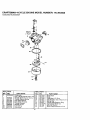
CRAFTSMAN
9" - 3.5 H.P. EDGER 536.797460
HANDLE ASSEMBLY
@
339591
REF.
NO. PART NO.
PART NAME
NO.
400
401
402
403
404
405
406
407
4081
4O9
410
411
412
Bracket, Handle
Carriage Bolt 5/16-18x 75
Nut, 5/16-18 Hexwdfllk
Handle, Lower 7/8"
Flatwasher .333x.87x 119
Handle, Depth Adjust
Screw, 5/16-18xl.25
Spring
Nut, 5/16-18 Reghexctrlk
Bracket, Quadrant
Rope Guide
Screw, 1/4-20xl .25
Nut, 1/4-20 Reghexctrlk
415
416
417
418
419
420
421
422
423
424
425
426
427
337323-833
57101
45174
332232-853
45602
337321-853
180081
25644
1498
337322-8531
321354
180024
1502
REF
16
PARTNO.
337713-853
337744
337775
314276
339489
°
339229
57796
340162
57444
180081
1498
337326
36368
PART NAME
Handle, Upper
Bail, Operator Control
Spring, Torsion
Nut, Push on 1/4
Cap, Operator Control
Insulator, Operator Control
Screw, #6x.50 Plastite
Clip, Grounding
Cable Tie
Screw, 5/16-18x 1.25
Nut, 51/6-18 Reghexctrlk
Control Rod
Hair Pin
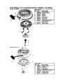
CRAFTSMAN
9" - 3.5 H.P. EDGER 536.797460
WHEELS/LINKAGE ASSEMBLY
O
339590A
REF
NO.
PARTNO.
PART NAME
101
102
103
104
105
106
107
108
109
339286
339146
20864
337871-833
339284
417098
337333
339079
27142
Front Axle
Spring, Axle Torsion
Ring, Ret. E.
Bracket, Front Wheel
Axle, Rear Vertical
Flatwasher .531 x 1.06x.063
Bracket, Linkage
Tire & Rim 7xl.50
Shoulder Bolt, 3/8-16
REF
NO.
110
111
115
116
117
118
120
121
PARTNO.
120394
1499
337327
584593
4230
36368
49998
2968
PART NAME
Flatwasher .406x.81x.065
Nut, 3/8-16 Reghexctrlk
Rod. Control
Nut, Trunnion 5/16-24
Flatwasher .328x.68x. 104
Hair Pin .072 Diaxl. 13Lg
Flatwasher .520xl .25x.209
Flatwasher .504x.75x.059
DECALS
REF.
NO. PART NO.
800
801
802
803
804
805
8_
807
808
69711
338984
338980
324860
3_475
324476
402862
402859
PART NAME
Reference Only
Decal, Information Danger
Decal, Recoil Cover
Decal, Engine Sears
Decal, Blade Rotation
Decal, Danger Blade
Decal, Warning Edger
Decal, Eng. Cont. Lever
Decal, Blade Height
339592A
17
CRAFTSMAN
4-CYCLE
ENGINE MODEL NUMBER:
143.963508
1
301
370A
260 f
Q"- 292
4OO
• 285
135
130
126
/
120
119
125
t5
.14
18
174
46
185
178
18
17
CRAFTSMAN
REF.
NO.
PART NO.
1
36470A
2
6
7
26727
33734
36557
12A
36558
12B
14
15
16
17
18
19
20
30
40
40
34695
28277
30589
32651
131335
$50548
36281
32600
34460A
34514
34515
40
34516
41
32538B
41
32548B
41
32549B
42
42
42
43
45
28986
28987
28988
20381
30963B
46
48
49
50
52
69
70
32610A
27241
28594
35990
29914
35261
30571C
72
75
80
81
82
36083
26208
30574A
30590A
30591
83
86
89
90
92
93
100
103
30588A
650488
610961
611123
650815
650816
34443A
651007
110
110A
119
120
125
36816
36230
36437
36474
36471
125
36472
126
29314B
4-CYCLE
ENGINE MODEL NUMBER:
PART NAME
Cylinder
(Incl. 2, 7, 20, & 125)
Dowel
Breather Element
Breather Assy(Incl.6 &
12A)
Breather Cover & Tube
(thcL 12B)
Breather Tube Elbow
Washer
Governo Rod(Inc114)
Governor Lever
Governor Lever Clamp
Screw, 8-32 x 5/16"
Extension Spring
Oil Seal
Crankshaft
Piston,Pin&RingSet(std)
Piston,Pin & Ring Set
(().010 OS)
Piston,Pin & Ring Set
(0.020OS)
Piston& Ring Assy
(Std) (lnc143)
Piston& Pin Assy
(.010" OS) Inc143
Piston& Pin Assy
(.020" OS (Inc143)
Ring Set (Std)
Ring Set (.010" OS)
Ring Set (.020" OS)
Piston Pin Retain Ring
Connecting Rod Assy
(Inc146 & 49)
Connecting Rod Bolt
Valve Lifter
Oil Dipper
Camshaft (BCR)
Oil Pump Assy.
Mountin I Flange Gasket
Mountin 1Flange
(Incl 72 hru 83, 311)
Oil Drain Plug
Oil Seal
Governor Shaft
Washer
Governor Gear Assy
(tncl 81 )
Governor Spool
Screw 1/4-20 x 1-1/4"
Flywheel Key
Flywheel
Belleville Washer
Flywheel Nut
Solid State Ignition
Screw, TorxT-15, 10-24
x 15/16"
Ground Wire
Ground Wire
Cylinder Head Gasket
Cylinder Head (Inc1130)
Exhaust Valve (Std)
(Incl. 15I)
Exhaust Valve (1/32" OS
(Inc1151)
Intake Valve (Std)
(Inc1151)
REF.
NO.
PART NO.
126
29315C
130
132
135
6021A
650708
35395
150
151
169
172
174
178
35991
31673
27234A
32755
30200
29752
179
182
184-
30593
6201
26756
185
i 186
J200
36544
34337
35727
202
203
204
205
206
207
209
215
223
224
238
239
241
245
250
260
261
262
275
277
285
287
290
292
300
36482
31342
650549
650777
610973
34336
30200
32410
650451
34690A
650932
34338
35797
35066
35065
36420A
30200
650831
35708
650795
35000A
650926
34357
26460
35586
301
311
313
370A
370B
380
390
400
35355
27625
34080
36261
35169
632046A
590694
36475
•
143.963508
PART NAME
Intake Valve (1/32" OS)
(Ind 151)
.
Screw 5/16-18 x 1-1/2
Washer
Resistor Spark Plug
(RJ 19LM)
Valve Spring
Valve Spring Cap
Valve Cover Gasket
Valve Cover
Screw 10-24 x 9/16"
Nut & Lock Washer
1/4-28
Retainer Clip
Screw 1/4-28 x 7/8"
Carburetorto intake
Pipe Gasket
Intake Pipe
Governor Link
Control Bracket (Ind.
202 thru 206)
CompressionSpring
CompressionSpring
Screw 5-40 x 7/16
Screw, 6-32 x 21/32"
Terminal
Throttle Link
Screw 10-32 x 9/16"
Control Knob
Screw 1/4-20 x 1•
Intake Pipe Gasket
Screw 10-32 x 49/64"
Air Cleaner Gasket
Air Cleaner Collar
Air Cleaner Filter
Air Cleaner Cover
Blower Housing
Screw 10-24 x 9/16"
Screw 1/4-20 x 1/2"
Muffler (Inc1277)
Screw 1/4-20 x 2-1/4"
Starter Cup
Screw 8-32 x 21/64"
Fuel Line
Fuel Line Clamp
Fuel Tank
(Inc1292 & 301)
Fuel Cap
Oil Fill Plug
Spacer
Lubrication Decal
Control Decal
Carburetor (Inc1184)
Rewind Starter
Gasket Set
You may order a spark arrestor kit 36664 which
contains muffler, screen and hardware.
This engine could have been built with 590737
starter. Refer to the design of the rope pulley
strength ribs for part identification. Individual
starter parts do not interchange.
!9
CRAFTSMAN
Carburetor
4-CYCLE ENGINE MODEL NUMBER:
143.963508
No,632046A
I
I
I
-30
REF. PART
NO. NO.
0
632046A
1
2
4
5
6
7
16
25
631615
631767
631184
631183
631616
650506
631775
631700
PART NAME
Carburetor
_nct, 184 of Engine Parts List)
hrottle Shaft & Lever Ass'y,
Throttle Return Spring
Dust Seal Washer
Dust Seal (Throttle)
Throtter Shutter
Shutter Screw
Fuel Fitting
Float Bowl
REF.
PART
NO.
27
28
29
30
31
35
40
44
48
NO.
631024
632019
631028
631021
631022
632047
631937A
631334
631027
2O
• PART NAME
Float Shaft
Float
Folat Bowl "O" Ring
Inlet Needle, Seat, Clip (incl 31
Spring Clip
Primer Bulb/Retainer Ring
High Speed Bowl Nut
Bowl Nut Washer
Welch Plug Atmosphe=ic Vent
CRAFTSMAN
4-CYCLE ENGINE MODEL NUMBER: 143.963508
Starter No. 590694
]
REF. PART
NO. NO.
590694
1
590599,4
2
590600
3
590696
4
590601
5
590697
6
590698
7
590699
8
590700
590695
12
8
13
590535
590701
PART NAME
Rewind Smiler
Spring Pin (Incl.4)
Washer
Retainer
Washer
Brake Spring
Starter Dog
Dog Spring
Pulley & Rewind Sprg Assy.
Starter Housing Assy
(_40° grommet)
Starter Rope
Starter Handle
11
n 5
2
Starter No. 590737
11
8
I REF, PART
NO. NO.
!3"
16
11
12
13
14
21
590737
590740
590616
590617
59O618A
590687A
590535
590701
590741
PART NAME
Rewind Starter
Retainer
Starter Dog
Dog Spring
Pulley&RewindSpring Ass)
Starter HousingAssy
Starter Rope
Starter Handle
LockingTab
For the repair or replacement parts you
need delivered directly to your home
Call 7 am-7 pm, 7 days a week
1-800-366-PART
(1-800-366-7278)
Pare ordenar piezas con entrega
a domicilio -1-800-659-7084
For in-house major brand repair service
Call 24 hours a day, 7 days a week
1-800-4-REPAIR
(1-800-473-7247)
Para pedir servicio de reparacion a
domicilio - 1-800-676-5811
For the location of a Sears Parts and
Repair Center in your area
Call 24 hours a day, 7 days a week
1-800-488-1222
For information on purchasing a Sears
Maintenance Agreement or to inquire
about an existing Agreement
Call 9 am -5pm, Monday-Saturday
1-800-827-6655
When requesting service or ordering
parts, always provide the following
information:
• Product Type
• Part Number
• Model Number
• Part Description
8I/AR8
America's
Repair
Specialists
Printed In U.S.A.