1
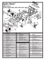
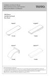
LITERATURE NUMBER MPD 33179 hydro flame TM 8500-IV Series Furnace MODELS 9 8516, 8520, 8525, 8531, 8535 Technical Installation Manual ENGLISH, FRANCAIS •Installation •Maintenance (et Canada) Effective 1/08 THIS INSTRUCTION MANUAL IS FOR USE BY AN AUTHORIZED SERVICE TECHNICIAN TO INSTALL AN ATWOOD - hydro flame TM INDEX FURNACE. ..............................................................1 ..................................................................1 WEIGHT ........................................................................1 MINIMUM CLEARANCE TO FLOORBOARDS, WALLS, & SIMILAR COMBUSTIBLE BUILDING MATERIALS..................................2 SAFETY INFORMATION ..................................................................1-2 FURNACE INSTALLATION ..................................................................2 WALL CUTOUTS ..........................................................................2 DUCTING ................................................................................2-3 Required Minimum Discharge Chart ............................................3 Flexible Ducting ......................................................................3 Floor Ducting ........................................................................3 OPTIONAL INSTALLATION - BOTTOM DISCHARGE KIT ..................................3 OPTIONAL INSTALLATION - EXTENSION BOX KIT ......................................3 OPTIONAL INSTALLATION - FLEX ADAPTER KIT ........................................3 PROPANE GAS CONNECTION ............................................................3 ELECTRICAL CONNECTIONS ..............................................................3 Conductor Sizing Table ............................................................3 Thermostat Installation ............................................................4 DOOR INSTALLATION ....................................................................4 Horizontal and Vertical Door Option ............................................4 Recess Bezel Door Option ........................................................4 DRAFT CAP ASSEMBLY ..................................................................4 OPTIONAL FURNACE INSTALLATION - Recessed Furnace ........................4-5 SYSTEM CHECK TESTS ....................................................................5 PROPANE GAS PRESSURE ..............................................................5 STATIC PRESSURE ........................................................................5 DC WIRING DIAGRAM ......................................................................5 ILLUSTRATIONS ............................................................................6 REPLACEMENT PARTS LIST & DRAWING ..............................................7 FURNACE SPECIFICATIONS TO THE INSTALLER: THESE INSTRUCTIONS MUST BE SUPPLIED WITH THE FUR- DIMENSIONS NACE TO THE CONSUMER. TO THE CONSUMER: PLEASE RETAIN THESE INSTRUCTIONS FOR FURTHER REFERENCE. This furnace design has been certified for installation in recreation vehicles as a MSP Category III furnace. Follow this installation instruction to insure safe operation of the furnace. Failure to install furnace according to this installation instruction nullifies the furnace warranty. SAFETY ALERT SYMBOLS Safety Symbols alerting you to potential personal safety hazards. Obey all safety messages following these symbols. WARNING avoid possible injury or death CAUTION avoid possible injury and/or property damage WARNING FIRE OR EXPLOSION • If the information in this manual is not followed exactly, a fire or explosion may result causing property damage, personal injury or loss of life. FOR YOUR SAFETY WARNING FIRE OR EXPLOSION SPECIFICATIONS MODEL WHAT TO DO IF YOU SMELL GAS # 8516-IV 8520-IV 8525-IV (W.C. = Water Column) 8531-IV 8535-IV BTU Input 16,000 20,000 25,000 30,000 34,000 Duct Static Pressure .20˝ W.C.* .10˝ W.C.* .10˝ W.C.* .10˝ W.C.* .10˝ W.C.* 12 Volt Amperage (AMPS) 4.6 4.6 7.6 7.6 9.8 Watts 55 55 91 91 118 12 12 12 12 12 Power Supply (VOLT DC) Recommended Return Air 80 in2 80 in2 80 in2 80 in2 80 in2 2 2 2 2 MINIMUM RETURN AIR 65 in 65 in 65 in 65 in 65 in2 • Evacuate ALL persons from vehicle. • Shut off gas supply at gas container or source. • DO NOT touch any electrical switch, or use any phone or radio in vehicle. • DO NOT start vehicle’s engine or electric generator. • Contact nearest gas supplier or qualified Service Technician for repairs. • If you cannot reach a gas supplier or qualified Service Technician, contact the nearest fire department. • DO NOT turn on gas supply until gas leak(s) has been repaired. Installation and service must be performed by a qualified Service Technician, Service Center or gas supplier. DIMENSIONS 1 ALL MODELS WIDTH HEIGHT DEPTH Casing Door Recess Bezel 16-1/2˝ 19-1/4˝ 20-9/16˝ 7-3/8˝ 9-1/4˝ 11-1/2˝ 18˝ 1/4˝ WEIGHT FURNACE SHIPPING 30 lbs 32 lbs MINIMUM CLEARANCE TO NOTE: The direct high voltage spark ignition generates a radio frequency that could cause interference with other microprocessor based equipment. Locate equipment at least five feet (5’) from furnace location. If this distance cannot be maintained, purchase MPD 37773 (a shielded high voltage lead). FLOORBOARDS, WALLS & SIMILAR COMBUSTIBLE BUILDING MATERIALS* MUST BE PROVIDED THE FULL LENGTH AND WIDTH OF UNIT HORIZONTAL TOP AND SIDES ------1/2˝ REAR VERTICAL TOP AND SIDES ------1/2˝ REAR --1˝ --1˝ BOTTOM BOTTOM --3/16˝ ------0˝(SLIDE PLATE) Spacing of 1/4˝ to ducting within 3 feet of furnace must be provided unless UL listed wire bound vinyl ducts are used. All ducting material should be rated for continuous use at 200˚F. NOTE: Clearances are specifically for plywood or similar building materials surrounding furnace (i.e. furnace should NOT be located under furniture or in closet space where clothing or other material could be located.) NOTE: Furnace efficiency rating is a thermal rating determined under continuous operating conditions, independent of any installation. Efficiency rate is given at 77% minimum, actual efficiency rating may be higher. *When furnaces are installed to minimum clearances, an additional 16 in2 of return air must be provided to blower side of furnace, or a 2˝ clearance the full length and height on blower side must be maintained. WARNING CARBON MONOXIDE POISONING Properly seal door, adjust draft cap (OR ON MODELS WITHOUT DOOR) install vent assembly) to prevent carbon monoxide from entering coach. • DO NOT draw combustion air from living area. DO NOT vent exhaust air into the living area or an enclosed porch. Return air is supplied through openings in furnace casing. All return air passages must be kept clear for furnace to function properly. Refer to MINIMUM CLEARANCE TO FLOORBOARDS, WALLS & SIMILAR COMBUSTIBLE BUILDING MATERIAL. The total unobstructed return air opening size(s) must NOT BE LESS than specified in SPECIFICATIONS - MINIMUM RETURN AIR. Failure to meet minimum return air requirements nullifies furnace warranty. WARNING STANDARD FURNACE INSTALLATION General Installation - LOCATION CARBON MONOXIDE POISONING Install furnace through an exterior wall. install furnace near tilt-out rooms, slide-outs, doors or other projections that could obstruct furnace exhaust. • Locate furnace near midpoint of coach for single furnace applications. • DO NOT install vent in areas where projections or door openings come within 6˝ of vent tube opening. • DO NOT install furnace in an area where wires, pipes, or other objects will interfere with installation or operation of furnace. • It is not recommended to install furnace on material that restricts return air, such as directly on carpet, or soft material (like vinyl). • If you must install furnace on carpet or soft material, install furnace on cleats, or on a wood or metal panel extending the full width and depth of furnace plus minimum clearances to combustibles. • DO NOT use petroleum or citrus type cleaners on plastic parts, as damage may occur. • Furnace must be installed and vented to these instructions. • Improper installation, adjustment, alteration, service or maintenance can cause injury or property damage. • Improper installation location may cause furnace to produce negative pressure, affecting combustion air or venting of other appliances. • • DO NOT CRITICAL INSTALLATION WARNINGS install furnace on material that restricts return air, like carpet or any soft material such as vinyl. • DO NOT install furnace where clearance to combustibles cannot be maintained. • DO NOT modify furnace in any way. • DO NOT alter furnace for a positive grounding system. • DO NOT HI-POT furnace unless electronic ignition system (circuit board) has been disconnected. • DO NOT use battery charger to supply power to DC model furnace even when testing. • DO NOT use 120 volt AC current with DC models. • DO NOT use furnace cabinet area as a storage compartment. • DO NOT vent furnace with venting system serving another appliance. • DO NOT vent furnace to an outside enclosed porch area. • DO NOT use for temporary heating of buildings or structures under construction. • Protect building materials from degrading from flue gas exhaust. • Protect furnace electrical components from water. • DO NOT USA AND CANADA • WALL CUTOUT OPTIONS RECOMMENDED WALL THICKNESS DO NOT OVERSIZE HOLE 1-1/2˝ to 2-1/2˝ - OVERSIZING CAN RESULT IN WATER LEAKAGE A B C (FIG 1) 17˝ 7-1/2˝ 19˝ VERTICAL (FIG 2) 7-1/2˝ 17˝ 19˝ (FIG 1) 19-1/2˝ 10˝ * RECESS BEZEL *RECESS BEZEL:To cut rounded corners: with radius blocks 2-1/8˝ radius without radius blocks a 45˚ angle EXTERIOR WALL CUTOUT HORIZONTAL CAUTION PERSONAL INJURY allow furnace tabs to protrude through side wall cutout opening during installation process until door is installed and tabs are bent over. Tabs have sharp edges. - FOLLOW ALL APPLICABLE STATE AND LOCAL CODES - • DO NOT IN THE ABSENCE OF LOCAL CODES OR REGULATIONS, REFER TO CURRENT STANDARDS OF: Recreation Vehicles ANSI A119.2/NFPA 501C. National Fuel Gas Code ANSI Z223.1 and/or CAN/CGA B149 Installation Codes • Federal Mobile Home Construction & Safety Standard, Title 24 CFR, part 3280, or when this Standard is not applicable, the Standard for Manufactured Home Installations (Manufactured Home Sites, Communities and Set-Ups), ANSI A255.1 and/or CAN/CSA-Z240 MH Series, Mobile Homes. • Ground-National Electrical Code ANSI/NFPA No. 70 and/or CSA C22.1 • Park Trailers ANSI 119.5 • • ALL OPTIONS: Place furnace in cavity. DO NOT have tabs protrude outside exterior wall until door is ready to be installed. DUCTING (FIG 4-7) Proper duct installation is critical to operation of furnace. When installing ducts, use materials rated for continuous use at 200˚F. - USING SIDE DUCT OPTIONS - must have a minimum of one duct from both left and right side of casing. HORIZONTAL INSTALLION 2 Required Minimum Discharge - (also see STATIC PRESSURE TEST) MODELS 4. Fasten plenum plate over cutout. 5. Position gasket on plenum plate. 6. Set furnace on gasket, make sure gasket remains in position. 7. Fasten extension box to floor with two 1/2˝ sheet metal screws. 8. Additional ducting can be used to maintain correct static pressure. REQUIRED DISCHARGE 8516-IV, 8520-IV ............................................................24in2 8525-IV & 8531-IV ........................................................36in2 8535-IV ..........................................................................48in2 ALL MODELS - TOP OR BOTTOM DISCHARGE SYSTEMS ..................48in2 8525-IV, 8531-IV, 8535-IV VERTICAL INSTALLATION ..............48in2 - FLEX ADAPTER KIT (FIG. 7) A flex adapter FIG 15 #26 may be used to provide more flexibility for alignment of discharge opening on hard duct systems. This system can be used on all models installed horizontally or vertically providing ducting from rear of furnace without using side ducts. 1. Remove three knockouts from rear of furnace. 2. If cutout is required, use placement and cutout dimensions for the EXTENSION BOX (FIG. 6). 3. Install duct adapters (7-A) in each opening. 4. Place flex adapter plate (7-C) with foam tape against hard ducting, making sure openings line up. 5. With plate held in place, fasten plate to ducting (7-D). 6. Install three duct adapters into flex adapter plate. 7. Attach flexible ducting (7-B) from furnace to flex adapter plate and secure ducting in place. 8. Additional ducting can be used to maintain correct static pressure. OPTIONAL INSTALLATION (EXCEPT WHEN USING THE THREE REAR DUCT OPENINGS OR MODELS WITHOUT DOOR) See MINIMUM CLEARANCE TO FLOORBOARDS, WALLS & SIMILAR COMBUSTIBLE BUILDING MATERIALS. • Each 4-inch duct opening provides 12 in2 of discharge area. Provide an extra 12 in2 of non closeable duct discharge area for each closeable register used. • Use of 2˝ ducts does not count toward achieving minimum discharge requirements. Ducting in dead air space with no return air, such as holding tank areas, does not count toward achieving minimum discharge requirements. • Adjust ducting installation to obtain air rise of 100˚F-130˚F. • Flexible Ducting Systems When designing Flexible Duct Systems: • avoid sharp bends or crushed ducts • stretch all ducts and run them directly to outlets, keeping quantity and angles of bends to a minimum 1. Remove knockout plates from desired outlets. 2. Attach a duct adapter to each opening, by inserting flange over casing, locking the tab into casing slot and turning adapter 90˚. 3. Attach and secure FOUR-INCH flexible ducts to adapters. 4. Run ducts to desired location within RV, secure to registers. 5. Additional ducting may be needed to maintain correct static pressure. PROPANE GAS CONNECTION (FIG. 1) 1. Connect gas line to brass fitting on right side of furnace. Be sure all male pipe threads, other than flare fittings, are treated with a sealing compound resistant to the action of propane (LP) gas. DO NOT put sealing compound on flare fittings. WITH DOOR ONLY - BOTTOM/TOP DISCHARGE OR VERTICAL BOTTOM (FIG 5) 1. Remove bottom/top discharge cover plate. This ducting option must be connected to a ducting system. FIG 15 #4 -GASKET AND PLENUM PLATE is available when attaching furnace. 2. If cutout is required: • Remove slide plate (1-E) and gas inlet plug (1-F) from furnace. • Insert gas line (1-G) through gas inlet plug (DO NOT CUT). • Connect gas line through gas inlet plug inside furnace casing immediately ahead of gas control valve. • A 1/8˝ N.P.T. plug is accessible for test gauge connection on gas valve assembly. 2. A 3/8˝ flared fitting connection is provided at gas control valve inlet for gas supply connection to furnace. The gas supply line of the furnace must be of adequate size to provide 11˝ W.C. gas pressure. This pressure must be maintained under maximum flow conditions with all gas appliances in operation. 3. Use two wrenches to hold brass fitting and flare nut when tightening gas line to brass fitting. DO NOT twist valve assembly (FIG. 8). BOTTOM DISCHARGE(FIG 5) ELECTRICAL CONNECTION (FIG. 14) Hard Ducting Floor Systems When designing Hard Ducting Systems: • undersize ducting will cause high temperature limiting • oversize ducting will cause inadequate air flow from registers • when hard ducting is 1-1/2˝ in depth, an additional flex duct may be needed to maintain installation static requirements • DO NOT install floor registers within 2 feet of return air openings. OPTIONAL INSTALL FLOOR CUTOUT A 8-1/4˝ B 9-1/2˝ C 6-1/4˝ D 1/4˝ WARNING 3. Fasten plenum plate (5-E) over floor cutout. If a gasket and plenum plate are not used, seal furnace to hard duct system making sure seal is air-tight and continue with STEP 5. 4. Position gasket (5-F) on plenum plate. 5. Set furnace on gasket, make sure gasket remains in position. 6. Additional ducting can be used to maintain correct static pressure. OPTIONAL INSTALLATION INJURY OR PROPERTY DAMAGE • Label all wires before disconnecting for servicing. Wiring errors can cause improper and dangerous operation. Verify proper operation after servicing. • Disconnect electrical power before servicing. Conductor Sizing Table - MAX. 10% VOLTAGE DROP - (12 VDC) - EXTENSION BOX KIT (FIG 6) CURRENT DRAW (AMPS) FIG 15 #7 Extension Box #7 and FIG 15 #54 Plenum Plate may be used for top or bottom discharge installation. A casing extension box adds 6˝ of depth to furnace. 1. Remove three knockouts from rear of furnace. 2. If cutout is required: FLOOR CUTOUT (FIG. 6) EXTENSION BOX A 18˝ B 1/2˝ C 5˝ D 16˝ 3 GAGE 18 16 4 5 6 7 8 9 57 87 43 65 34 52 29 43 25 37 21 33 19 29 CAUTION E 1/4˝ 10 15 MAX. LENGTH OF SAE CONDUCTOR (IN FEET) FROM SOURCE TO DEVICE 17 26 11 17 PROPERTY DAMAGE • This connection is for low-voltage battery or direct current only. Do not connect to 120- or 240- volts AC. 3. Place extension box with foam gasket against furnace, making sure the three openings are enclosed within extension box. With extension box held in place, secure with two 1/2˝ sheet metal screws. 3 This furnace is designed for negative ground 12 volts DC only. DO NOT attempt to alter furnace for a positive ground system or connect the furnace directly to 120 volts AC. Damage to furnace components will occur and warranty will be voided. Use a minimum of 18 GA wire to minimize voltage drop. Furnace must be installed so electrical components are protected from water. To make electrical connections see wiring diagram FIG. 14. 1. Route wiring to left side of furnace. 2. Connect red wire to positive side of power supply. 3. Connect yellow wire to grounded side of power supply. 4. Connect blue wire marked positive thermostat to + side wire of thermostat using 22-18 GA stranded wire. 5. Connect other blue wire to other thermostat lead using minimum 22-18 GA stranded wire. around gas line where it enters gas inlet plug. along welded joints of two bottom corners of casing. 4. The inlet plug and slide plate must be in closed position and bezel flange inside of casing. Insert six mounting tabs through slots provided in bezel, bezel must be tight against casing and cutting into RTV sealant on bezel. 5. Bend tabs flush with door bezel, aligning holes in tabs with slots in door bezel. 6. Install 12 mounting screws. DO NOT deform bezel. 7. Remove excess sealant from around door bezel and visually inspect door bezel to make sure it is completely sealed. 8. Secure mounting legs on the back of the unit to floor for horizontal installation. For vertical installation secure legs to a vertical member that is attached to floor. Seal around slide plate, gas plug and joint between control box right side and back wall. • • For best furnace performance when power supply is from a converter equipped with a charging port, wire converter to furnace parallel with battery. This provides consistent voltage to furnace, increasing component life, filtering power surges and AC spikes. OPTIONAL INSTALLATION Each model with door is shipped with a standard field harness connection with 12˝ wire leads. An optional field harness with a double end is available in bulk FIG 15 #55. This harness contains 12˝ leads, a four pin housing, and standard six pin housing FIG. 10-F NOTE: All units are supplied with a power switch which when turned off or servicing will remove power through furnace wiring. Switch must be in ON position for furnace to operate FIG 1-D. POWER SUPPLY Atwood Mobile Products highly recommends the use of an electronic (solid state) converter with clean, clear power output. This will assure the life of the electronic controls and motor life could be extended as much as 500% beyond typical linear converter applications. DRAFT CAP ASSEMBLY (FIG. 12) WARNING THERMOSTAT INSTALLATION CARBON MONOXIDE POISONING • Properly adjust draft cap to prevent carbon monoxide from entering coach. The thermostat is very sensitive. HANDLE WITH CARE AT ALL TIMES. Locate thermostat 48˝ to 54˝ above floor on an INTERIOR wall away from areas of abnormal heat or cold. EXTERIOR wall location must have a 3/4˝ spacer between thermostat and exterior wall. Follow manufacturer’s installation instructions provided with thermostat. When thermostat is not supplied, use a thermostat rated for 12 VDC or 24 VDC minimum 1 AMP. With wing nut 12-C loose on draft cap assembly, close door 12-A and adjust draft cap 12-D. The draft cap assembly must be pulled out tight gainst door screen 12-B. Open door 12-A and tighten wing nut 12-C. OPTIONAL FURNACE INSTALLATION DOOR INSTALLATION (FIG. 9-11) RECESSED FURNACE - FIG 13 INSERT WARNING • - RECESS BEZEL 1. Position and secure mounting brackets to door framing on each side of opening, allowing 5/16˝ from end of bracket face to outside of coach. 2. Pull furnace forward until edge of control box is flush with recess pan, with mounting tabs protruding through exterior wall. 3. Insert recess bezel and door bezel until furnace tabs go through notches on door bezel. RTV type sealant must be applied to entire back flange of both parts creating a water tight seal. Secure to mounting brackets. 4. Fasten recess bezel and door bezel to brackets with three screws on each side. Do not deform recess bezel or door bezel. 5. Bend tabs over and secure with six screws. Fill tab slots with RTV type sealant after installing furnace. Only intake and exhaust portion of furnace is viewed from exterior of coach when furnace is installed. • Furnace must be removable for service. 2 • All 65 in return air should be taken from interior of coach. CARBON MONOXIDE POISONING Properly seal door to prevent carbon monoxide from entering coach. Areas to be sealed. • Coach access door butting against furnace pan cover. • Bottom edge of cut out section in metal pan cover. • Draft cap assemblies to be maintained tight against the coach outside compartment doors where intake screens will be mounted. • INSTALLATION OF DRAFT CAP ASSEMBLY-DO NOT PULL COMPLETELY OUT OF EXHAUST TUBE. Draft Cap assembly must over lap 1.25˝ inside exhaust tube. HORIZONTAL & VERTICAL INSTALLATION NOTE: STANDARD DOOR (FIG 10) or DELUXE DOOR (FIG 9) may be used alone or with optional RECESSED BEZEL (FIG 11). 1. Pull furnace forward until mounting tabs protrude through exterior wall. The edge of control box is flush with coach’s outer skin, (VERTICAL - with gas connection on bottom). 2. The door bezel must fit tightly, to prevent water leakage. NOTE: The furnace must always be installed level (front to back, side to side) to prevent water intrusion into the interior. 3. To prevent moisture from entering inside of coach, apply RTV type sealant to the following areas: HORIZONTAL & VERTICAL INSTALLATION • entire mounting surface of door bezel, making sure caulking is tight against inner flange of bezel. • fill tab slots with caulking after bending tabs over, securing with screws. VERTICAL INSTALLATION - YOU MUST CALK • around red gas inlet plug (slide plate and casing bottom intersect). • around back slide plate where it joins metal casing. 4 1. Remove four (4) outside tabs located on control box. Leave two (2) center tabs to mount door. Bend these two center tabs toward inside of control box area 90˚, as close to control box as possible, to maintain a good seal. Install two fastening clips provided. 2. Install furnace in coach as close to outer compartment door as possible. Furnace must maintain a pressure seal against gasket on screen to prevent flue products and water leakage from entering interior of coach. 3. Connect gas line to right side of furnace. Tighten gas fitting using two wrenches. Attach electrical wiring to left side of furnace. Attach red wire to positive connection and yellow wire to negative. Attach two blue wires to the thermostat wires. 4. Secure furnace to coach floor with four screws. LOCATE SCREWS TO AVOID DAMAGE TO ANY WORKING COMPONENTS, WHILE MAINTAINING PRESSURE SEAL AGAINST GASKET ON SCREEN. STATIC PRESSURE TEST (FIG. 1) Please refer to Engineering Addendum when installing the furnace. This will provide you with allowable maximum case static pressures with each possible variation of duct configurations. The addendum is available from your Atwood Field Service Representative or by calling Atwood Service Toll Free. CUTOUT RECOMMENDED WALL THICKNESS DO NOT OVERSIZE HOLE 1-1/2˝ - 2-1/2˝ - OVERSIZING CAN RESULT IN WATER LEAKAGE A 4-3/4˝ EXTERIOR WALL CUTOUT RECESS FURNACE(FIG 13) Reducing the number of duct turns and stretching the ducts will increase airflow and reduce static pressure. Adding ducts or increasing the discharge (hard duct) system will also reduce static pressure. B 5˝ 5. Place recess cover over top of furnace with all edges of door outside of control box. Hold firmly into place while using holes in door to locate mounting tabs and clips. Use #8 or #10 sheet metal screws to fasten door in place. You must follow the manufacturer’s recommendations and specifications for optimum performance and proper operation. DIAGNOSTIC CHART FAULT Follow STANDARD FURNACE INSTALLATION instructions for ducting, thermostat and draft cap assembly. LED INDICATION Internal Circuit Board Failure Limit switch/Airflow problems Flame Sense Fault Ignition Lockout Fault SYSTEM CHECKS WARNING Steady on, no flashing 1 flash with 3-second pause 2 flashes with 3-second pause 3 flashes with 3-second pause FIRE OR EXPLOSION • Never check for leaks with an open flame. PROPANE GAS PRESSURE TEST The furnace and any individual shut-off valve must be disconnected from gas supply piping system during any pressure testing of system at test pressures of more than 1/2 PSI. Before furnace is connected piping systems must be tested to be leak free. The test must maintain air pressure of at least 6˝ of mercury or 3 PSI for at least 10 minutes. The entire piping system must be maintained within a range of 10-14˝ W.C. when all appliances are in operation. Test gas connections for leakage with a leak test solution. 14 INSIDE FURNACE GROUND ELECTRODE MOTOR BLACK YELLOW RED RED VALVE YELLOW CIRCUIT BREAKER ON/OFFON SWITCHOFF YELLOW BLUE BLUE YELLOW BLW PWR SAIL SWITCH BLUE LIMIT SWITCH 4 4 5 5 3 3 6 6 + 12V DC NEG +THERMO THERMO THERMOSTAT IGNITION CONTROL RED WHITE RED 1 1 BLUE 2 2 12V DC SUPPLY WHITE RED YELLOW HIGH TENSION CUSTOMER SUPPLIED WIRING IMPORTANT: If any original wire has to be replaced, it must be replaced with type 105° C or its equivalent. Terminal Block on 85 Models only. 5 Note: On/OFF Switch may be separate or combined with Circuit Breaker. Access to Static Port (Accès à l’orifice statique) 8 1 2 A B E A C F Vertical Installation G D 1-1/4" B D 12 C B (Installation Verticale) C OR 1-1/4" 9 A 10 10 11 9 OR AVANT DU VEHICULE (EX 6 A B TE OU RIE TSID UR E DU RV VE HIC U LE 13 4 E OR OR A D C B A B D VERTICAL FOOT PRINT F E C A D C 7 B 5 6 ) hydro flame TM 8500-IV Series Furnace Models 8516, 8520, 8525, 8531, 8535 30 26 52 7 18 42 32 20 54 1 47 41 3 57 36 49 15 Cut Out & Cover Plate on Full Side Discharge ONLY 43 46 51 8 35 28 27 50 48 4 22 30 23 6 56 46 10 14 45 9 17 37 24 11 19 13 12 DRAWING 1 3 4 6 7 8 9 10 11 12 13 14 15 17 18 19 20 22 23 24 26 27 28 30 32 35 36 37 41 42 43 45 46 # DESCRIPTION Blower Wheel Motor Clamp Gasket/Plenum Plate Kit- Top & Bottom Burner Assembly Extension Box ON/OFF Switch Replacement Coil Combustion Wheel Door Hinges Door, Standard ORDER BY COLOR Door, Deluxe -SPECIFY COLOR Slide Plate Thermostat - specify color Valve Field Wiring Harness Draft Cap Assembly - Specity model Electronic Ignition Board Duct Adapters Duct Cover Plate Electrode Flex Adapter Plate Assembly Kit Gas Inlet Plug High Tension Lead Top/Bottom/Side Cover Limit Switch Motor Gasket Motor - specify rate Orifice - specify rate Sail Switch Element Assembly - specify model Exhaust Wall Gasket Recess Pan Assembly-SPECIFY COLOR Mounting Bracket DRAWING 47 48 49 50 51 52 54 56 57 N/S # DESCRIPTION Venturi Blower Housing Back Blower Housing Motor/Combustion Wall Circuit Breaker Control Board Mounting Bracket Plenum Plate, Extension Boot Door Fastener Kit Double Housing Field Harness High Voltage Lead - noise suppresion N˚ SUR LE SCHÉMA 1 3 4 DESCRIPTION 6 7 8 9 10 11 12 Ventilateur Bride de fixation du moteur Kit de joint d'étanchéité et de plaque de répartition d'air - haut et bas Brûleur Extension de boîtier Interrupteur MARCHE/ARRÊT Bobine de rechange Ventilateur d'air de combustion Charnières du panneau extérieur Panneau extérieur, standard DOIT ÊTRE COM- 13 Panneau extérieur, de luxe - PRÉCISEZ LA 14 15 17 18 19 20 Plaque coulissante Thermostat - PRÉCISEZ LA COULEUR Soupape Faisceau de câblage sur place Capuchon de refoulement Panneau d'allumage électronique MANDÉ PAR COULEUR 22 23 24 26 27 28 30 32 35 36 37 41 42 43 45 46 47 48 49 50 51 52 54 COULEUR 7 56 57 N/S Adaptateurs de conduit Couvercle d'ouverture de branchement de conduit Électrode Plaque adapatatrice de flexibles kit Raccord d'admission de gaz Fil haute tension Plaque de répartition d'air du haut, du bas et latéral Rupteur thermique Joint d'étanchéité du moteur Moteur - précisez la puissance nominale Lumière - précisez le calibre Interrupteur à abattant Élément de chauffage Joint entre le système d'évacuation et la paroi Cadre de fond-PRÉCISEZ LA COULEUR Support de fixation Pavillon d'aspiration Arrière du boîtier du ventilateur Boîtier du ventilateur Paroi moteur/ventilateur d'air de combustion Coupe-circuit Support de fixation du tableau de commande Plaque de répartition d'air, Extension de b oîtier Kit de fermeture du panneau extérieur Queue de cochon double Fil haute tension – suppression du bruit