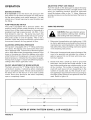
1
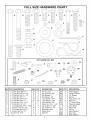
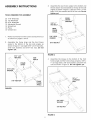
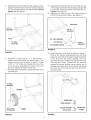
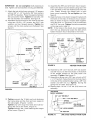
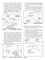
Agri-Fab ®
OWNERS
MANUAL
Model No.
45-0325
45 GALLON
ATV SPRAYER
CAUTION:
Read Rules for
Safe Operation
and Instructions
Carefully
•
•
•
•
Assembly
Operation
Maintenance
Repair Parts
SpeedEPart the
ra,,e,,
wa_
topurch_,_
partswww.speedepart.com
PRINTED
IN USA
FORM NO. 48598 (2/04)
RULES
FOR SAFE OPERATION
Any power equipment can cause injury if operated improperly
the equipment.
Exercise caution at all times when operating
or if the user does not understand
equipment.
how to operate
1.
2.
3.
4.
5.
6.
7.
8.
9.
Read this owners manual carefully before attempting to assemble or operate this sprayer.
Read your vehicle owners manual for operating and safety rules before using this equipment.
Never allow children to operate this sprayer, and do not allow adults to operate without proper instructions.
Do not allow anyone to ride on or sit on this sprayer. Do not allow passengers on the towing vehicle.
Keep the area of operation clear of all persons, particularly
small children. Also keep area clear of pets.
Read the chemical label carefully for instructions
and caution notes on handling and mixing of chemicals.
Wear eye and hand protection and wear protective clothing when handling and applying lawn chemicals.
Do not spray on windy days.
Attachment of this sprayer may affect your vehicle's braking and stability. Be aware of your vehicle's capabilities.
Refer to the safety rules in the vehicle owner's manual concerning
safe operation on slopes. Be aware of
changing conditions on slopes. STAY OFF OF STEEP SLOPES.
10. Operate at reduced speed on rough terrain, along ditches and on hillsides to prevent loss of control.
11. Follow maintenance
and lubrication instructions
as outlined in this manual.
LOOK FOR THIS SYMBOL TO POINT OUT
IMPORTANT
SAFETY PRECAUTIONS.
IT
MEANS--ATTENTION!
BECOMEALERT! YOUR
SAFETY IS INVOLVED.
Your sprayer carton contains parts as shown in the diagram below. The hardware package contains parts as shown
in the Full Size Hardware Chart on page 3. Identify all parts and lay out as shown.
CARTON CONTENTS
LOOSE PARTS IN CARTON
1.
2.
3.
4.
5.
6.
Spray Gun
Side Angles (2)
Tongue
Hose Hooks (2)
Transport Bracket
Wheels (2)
7
7.
8.
9.
10.
11.
12.
Hitch Bracket
Boom Mount Brackets (2)
Return (Bypass) Hose
Boom Hose Assembly
Tank
Rear Frame Angle
ii fJ
13.
14.
15.
16.
17.
18.
19.
Frame
Front
Boom
Boom
Boom
Boom
Axle
Strap
Frame Angle
Mount Assembly, L.H.
Mount Assembly, R.H.
Arm Assembly, R.H.
Arm Assembly, L.H.
FULL SIZE HARDWARE
CHART
J
H
jl
L
U
j
KEY QTY. DESCRIPTION
A
B
C
D
E
F
G
H
I
J
K
L
M
2
2
8
1
2
6
10
2
1
2
4
2
16
Hex Bolt, 3/8" x 4"
Hex Bolt, 3/8" x 2-1/2"
Hex Bolt, 3/8" x 1-1/4"
Hex Bolt, 3/8" x 1"
Hex Bolt, 3/8" x 3/4"
Hex Bolt, 5/16" x 1"
Hex Bolt, 5/16" x 3/4"
Hex Bolt, 1/4" x 2"
Carriage Bolt, 5/16" x 1-3/4"
Screw, #10-24 x 1/2"
Carriage Bolt, 3/8" x 1"
Hex Lock Nut, 1/4"
Hex Nut, 5/16"
KEY QTY.
N
O
P
Q
R
S
T
U
V
W
X
Y
Z
15
2
4
12
2
16
17
2
2
1
1
1
1
AA
DESCRIPTION
KEY QTY.
DESCRIPTION
Hex Nut, 3/8"
Hex Lock Nut, 3/8"
Flat Washer, 1"
Flat Washer, 3/8"
Lock Washer, 3/16"
Lock Washer, 5/16"
Lock Washer, 3/8"
Cotter Pin, 1/8" x 1-1/2"
Hair Cotter Pin, 3/32"
Hair Cotter Pin, 1/8"
Mounting Clamp
Plastic Knob
Hitch Pin
AA
BB
CC
DD
EE
FF
GG
HH
It
JJ
KK
LL
MM
NN
Wheel Spacer
Flanged Spacer
1/2" Spacer,
Spring
Hose Clamp, 1/4"
Nylon Tie
"Y" Valve Fitting
Pressure Gauge
Drain Body
Nylon Cap
O-Ring
Nylon Washer
Nylon Nut
Hose Gasket
2
2
6
2
1
8
1
1
1
1
1
1
1
3
ASSEMBLY INSTRUCTIONS
,
Assemble the rear frame angle to the bottom and
the two boom mount brackets to the top of the side
angles as shown in figure 2. Use four 5/16" x 1" hex
bolts, 5/16" lock washers and 5/16" hex nuts. Do not
tighten yet.
TOOLS REQUIRED FOR ASSEMBLY
J
(2)
(2)
(2)
(1)
(1)
(1)
(1)
1 ,
2,
7/16" Wrenches
1/2" Wrenches
9/16" Wrenches
Adjustable Wrench
Screwdriver
Pliers
Grease Gun
_°/
BOOM
5/16" x 1"
'_
MOUNT_BRACKET
/ i
HEX BOLT
I
REAR
FRAME
ANGLE
/
_
;,-
Remove all items from the carton and lay them out
as shown on pages 2 and 3.
Assemble the frame strap and the front frame
angle to the bottom of the two side angles as
shown in figure 1. Use eight 5/16" x 3/4" hex bolts,
5/16" lock washers and 5/16" hex nuts. Do not
tighten
yet.
FIGURE 2
5/16" x 3/4"
HEX BOLT
SIDE
4,
ANGLE
FRAME
STRAP
Assemble the tongue to the bottom of the front
frame angle and the frame strap using four 3/8" x
1" carriage bolts, 3/8" lock washers and 3/8" hex
nuts as shown in figure 3. Do not tighten
yet.
\
5/16" LOCK
WASHER
\
t
5/16" HEX NUT
318" x 1"
CARRIAGE
BOLT
FRONT
FRAME
ANGLE
FIGURE 1
I
FIGURE 3
4
5.
Assemble the axle through the side angles and the
tongue. Fasten the axle to the side angles using two
1/4" x 2" hex bolts and two 1/4" hex lock nuts. Do not
tighten
8.
Assemble the hitch bracket down through the slot
in the tongue and fasten it to the tongue using a 3/8"
x 1" hex bolt, a 3/8" lock washer and a 3/8" hex nut.
Tighten.
See figure 6.
Assemble the hitch pin and 1/8" hairpin cotter to
the hitch bracket and tongue. See figure 6.
yet. See figure 4.
9.
HITCH PIN
3/8" X 1"
HEX BOLT
AXLE
j.°
1/4" HEX
LOCK NUT
BRACKET
FIGURE 6
FIGURE 4
6.
7.
Assemble a wheel spacer, a 1" flat washer, a
wheel (valve stem facing out) and another 1" flat
washer onto the axle as shown in figure 5. Place
a 1/8" x 1-1/2" cotter pin through the hole at the
end of the axle, spreading the ends of the pin to
secure it. Repeat on other end of axle.
Fill wheel hubs with general purpose grease using
a grease gun.
10. Install the drain in the tank as shown in figure 7.
Place a 3/4" garden hose gasket onto the drain
body and insert the drain body through the bottom
of the tank from the inside. Beneath the tank,
assemble the nylon washer and then the nylon nut
onto the drain body. Tighten the nut securely
enough to prevent leaking, being careful not to
damage the plastic parts. Place the O-ring inside
the nylon cap and screw the cap onto the end of
the drain body.
f
1" FLAT
WASHER
\
1/8" x 1-1/2"
COTTER PIN
FIGURE 5
,,,
WHEEL
NYLON CAP__
FIGURE 7
O-RING
IMPORTANT:Do not overtighten bolts fasteningto
tank.Tightenuntillockwashersaresnugandflattened.
11. Attachthe tanktothe frameusingsix 1/2"spacers
withsix 3/8"x 1-1/4"hex bolts,3/8" lockwashers
and3/8"flat washers.Placethe spacersbetween
the tankandthe frame.Tighten the six boltsuntil
the lockwashersare flattened.Seefigure8.
12. Assemblethe hosehooksto the front of the tank
using two #10-24 x 1/2" screws, two 3/16" lock
washersand two flanged spacers.Tighten the
screwsuntil the lock washersare flattened.See
figure8.
14. Assemble the (RH) and (LH) boom mount assemblies to the boom mount brackets using two 5/16"
x 3/4" hex bolts, 5/16" lock washers and 5/16" hex
nuts. Fasten through the slotted hole in each
boom mount assembly. Do not tighten yet. See
figure 9.
15. Align the holes in the boom transport bracket with
the holes in the ends of the boom mount assemblies as shown in figure 9. Fasten them together
using two 5/16" x 1" hex bolts, 5/16" lock washers
and 5/16" hex nuts. Tighten the bolts assembled
in this step and in step 14.
NOTE:
If the holes in the boom mount assemblies
won't line up, temporarily
loosen the bolts which
fasten the boom mount brackets to the frame.
s
_.....
4\\\
!
FLANGED
3/16" LOCK /
WASHER
ii
Ji
rf
i
5116" x 314"
HEX BOLT
"BOOM
5116" x 1"
HEX BOLT /TRANSPORT
/ BRACKET
/
MOUNT
(LH) BOOM
ASSEMBLY
LOCK
5/16"
WASHERS
/
%
I
.5/16
........ HEX
....
NUTS
(RH) BOOM
MOUNT
ASSEMBLY
F
FIGURE 9
VIEWED
FROM REAR
16. Assemble a 3/8" x 3/4" hex bolt, 3/8" lock washer
and 3/8" hex nut to the hole shown in the bottom
of the welded bracket on the (RH) boom arm
assembly. Tighten. See figure 10.
17. Assemble a spring and a 3/8" hex nut onto a 3/8"
x 1-1/4" hex bolt. Fasten the bolt to the hole shown
3/8" FLAT
WASHER
3/8" LOCK
WASHER
3/8" x 1-1/4"
HEX BOLT
FIGURE 8
in the top of the welded bracket using a 3/8" lock
washer and 3/8" hex nut. Tighten,
leaving the
spring free to rotate. See figure 10.
18. Repeat steps 16 and 17 for the (LH) boom arm
assembly.
(RH) BOOM
MOUNT ASSEMBLY
318" x 314" HEX BOLT
13. Tighten securely the 12 bolts and nuts fastening
the frame strap and the front and rear angles to
the side angles. (Figures 1 and 2)
Tighten only until snug the 2 bolts and nuts fastening the axle to the frame. (Figure 4)
Tighten securely the 4 nuts fastening the tongue
to the frame. (Figure 3)
7_------ 318"x 1-1/4" HEX BOLT
SPRING
_3/8" REX NUT
(RH) BOOM
ARM ASSEMBLY
LOCK WASHER
3/8" HEX NUT
FIGURE 10
(RH) SIDE VIEWED
FROM REAR
19. Attachthe (RH) boomarm assemblyto the (RH)
boom mount assemblyas shown in figure 11,
usinga 3/8"x 4" hex bolt,three 3/8"flat washers,
andone 3/8" hex lock nut. Do not overtighten.
20. Place a 3/8" x 2-1/2" hex bolt throughthe loose
endofthe springandthenassemblea3/8" hexnut
onto the bolt. Fasten the hex bolt to the boom
mountassemblyusinga 3/8"lock washerand 3/8"
hex nut. Tighten the nuts, exposingone or two
threadson the end of the bolt. Seefigure 11.
21. Repeatsteps 19 and 20 for the (LH) boomarm
assembly.
3/8" x 2-1/2"
HEX BOLT
318"
HEX
NUT
7
24. Tie the hoses to the front of the boom using four
nylon ties per side as shown in the front view in
figure 13. After tightening,
cut excess length off
ends of ties.
25. Insert a 3/32" hair cotter pin into the welded pin at
each end of the boom. These pins will be used to
lock the boom arm to the transport bracket when
the arm is in the folded position. See figure 13.
3/32" HAIR COTTER PIN
o.q-oFF
VALVE
\%
(RH) BOOM
ARM ASSEMBLY
TIE TO
FRONT OF
BOOM
318"x 4" HEX BOLT
l
" FLAT WASHER
_
TIE TO FRONT
OF BOOM
3/8" FLAT WASHER
NYLON TIES
VIEWED
FIGURE 13
FROM FRONT
_ _'"_-"-_ 3/8" HEX LOCK NUT
3/8" LOCK WASHER
NOTE: To help prevent leaking, use thread tape when
assembling the "Y" valve fitting and the pressure
gauge in the following paragraphs.
3/8" HEX NUT
(RH) BOOM MOUNT ASSEMBLY
FIGURE 11
(RH) SIDE VIEWED
FROM REAR
26. Carefully screw the "Y" valve fitting onto the fitting
attached to the tee support bracket. The valve
levers should face up. See figure 14.
27. Carefully screw the pressure gauge into the top of
the tee fitting as shown in figure 14.
28. Place the 1/4" hose clamp over the end of the
spray gun hose. Push the hose onto the hose barb
on the front of the tee fitting. Secure the hose to
the barb with the hose clamp. See figure 14.
22. Attach the hose assembly
to the front of the
boom, with the nozzles pointing to the rear. Remove the nozzle nut, nozzle, strainer screen and
elbow nut, from the elbow fittings and place the
elbow through the hole at the end of the boom arm.
Secure it using the plastic elbow nut. Insert the
strainer screen and then assemble the spray nozzle
and the nozzle nut, keeping the nozzle opening
facing down while tightening.
See figure 12.
23. Attach the hose assembly tee fittings to the boom
using the same procedure as was used for the
elbows. See figure 12.
_
TEE SUPPORT "_-.
BRACKET
TEE FITTING
BOOM CONNECTING HOSE
ELBOW
ON-OFF VALVE
TEE
1/4"HOSE_
CLAMP J
ELBOW NUT
STRAINER
SPRAY GUN HOSE
SCREEN
SPRAY NOZZLE
NOZZLENUT
FIGURE 12
(RH) SIDE VIEWED
PRESSURE
GAUGE
FIGURE 14
FROM REAR
7
29. Connecttheboomconnectinghoseandthe return
(bypass)hose to the "Y" valve fitting, placinga
hosegasketin theswivel nuton eachhose.Insert
the returnhoseintothe top of tank.Seefigure15.
HOSE
IM PO RTANT:
31. Hook up
the red
positive
tion on
GASKET
Connect sprayer to 12 volt batteries only!
the wiring to the vehicle battery. Connect
wire on the fused wire harness to the
post on the battery or the "HOT" conneca vehicle switch or the ammeter.
The
brown wire may be grounded or connected to the
negative battery post. See figures 17 and 18.
IMPORTANT:
Keep wiring away from hot engine parts,
rotating parts and pinch points.
PUMP SWITCH
QUICK COUPLER
FIGURE 17
FIGURE 15
plug to come in contact with positive "hot"
CAUTION:
Never Fire
allowor negative
on
post
on battery.
explosionpinmay
result!
_.
30. Attach the sprayer to the vehicle hitch and then
attach the switch bracket to the rear rack of the
vehicle. Use the plastic knob, mounting clamp and
5/16" x 1-3/4" carriage bolt. See figure 16.
POSITIVE
"HOT"
POST
PLUG
PLASTIC KNOB
SWITCH BRACKET
NEGATIVE
POST
NEGATIVE PIN
t
12 VOLT TRACTOR BATTERY
FIGURE 18
i'_
MOUNTING
CLAMP
5116" x 1-3/4"
CARRIAGE BOLT
FIGURE 16
ADJUSTING
OPERATION
BEFORE
STARTING
It is important
to test the boom and spray gun with
plain water first to check the sprayer for leaks and to
set the spray pattern and nozzle pressure. If a leak
should occur, thread tape may be used to better seal
the fitting.
PUMP PRESSURE
OPERATING
ADJUSTMENT
OF BOOM NOZZLES
The boom valve on the "Y" fitting controls the flow to
all the boom nozzles. It should be either completely
open or completely closed. The two valves located on
the boom will turn the flow on or off to each outside
nozzle. Each valve should
open or completely
closed.
WIDTH
FIGURE 19
USING THE SPRAYER
[&
be set either
OF SPRAY
completely
PATTERN
CAUTION: Wear eye protection, gloves
and protective clothing when handling
and working with lawn chemicals.
1 ,
Determine the application rate (gallons per 1,000
sq. feet or gallons per acre) based on the chemical
manufacturers
recommendations.
Use this rate to
help select the pressure setting and tractor speed
in the following instructions.
2.
Determine the approximate square footage of the
area to be sprayed and estimate the number of
gallons required. Do not fill tank with more solution than needed.
PRESSURE
The sprayer is equipped with a "Y" fitting containing
two valves. The bypass valve controls the flow to the
return (bypass) hose. The amount of flow through the
return hose determines the operating pressure of the
boom or the spray gun. Adjust the bypass valve while
either the boom or the spray gun is in use to obtain the
desired pressure, indicated by the pressure gauge.
The tip chart on page 11 shows how different pressure
settings affect boom application rates.
ON-OFF
GUN NOZZLE
SWITCH
The pump is equipped with a pressure switch. The
pressure switch senses outlet pressure of the pump
and will turn off the electrical power to the pump at a
predetermined
high pressure point (45 PSI). If the
flow demand is very low, the pump may reach this
high pressure point and the switch will cause "cycling"
(the pump cycles on and off rapidly). This is not a
problem unless the pump continuously
cycles within
one second intervals for long periods of time.
ADJUSTING
SPRAY
Turn the nozzle on the spray gun to adjust the spray
from a cone shaped fine mist to a straight stream. The
spray gun operating pressure should be controlled
using the bypass valve on the "Y" fitting. Maximum
spray gun pressure can be attained when the boom is
shut off.
,
Decide how wide a swath you wish to spray with
each pass. Use just the two inside nozzles, or the
two inside nozzles plus one outside nozzle, or use
all four nozzles. The number of square feet covered with each pass will vary depending on the
number of nozzles used, but the amount of solution applied per square foot will not vary as long as
the same system pressure and speed of travel are
used. Refer to figure 19.
USING
2, 3 OR 4 NOZZLES
4. Set the desired boom pressure,spraying with
plain water while makingpressureadjustments.
Forbestresultsstayin the 20 to30 PSIrange.(At
10 PStthe spray patternbeginsto breakup, and
at 40 PSI somedrift develops.)Refer to the tip
chart on page 11.
5. Determinetheappropriatespeedatwhichtotravel,
based on the chosen pressure setting and the
recommendedapplicationrate. Usethe tip chart
on page 11.
.
7.
.
9.
MAINTENANCE
1
.
2.
Do not store sprayer
with any solution
left in tank.
Periodically
clean the strainer in the end of the
intake hose at the bottom of the tank. Remove the
nylon swivel nut from the hose, pull out the screen
and flush it with clear water.
AFTER
To determine the throttle setting for attaining the
appropriate speed, mark off 100,200 and 300 feet
intervals. The speed chart at the bottom of page
11 indicates the number of seconds it takes to
travel these distances. Set the throttle and, with a
running start, travel the distances in the number of
seconds indicated by the speed chart. Once you
have determined
the throttle and gear settings
needed, mark the throttle location so that you can
easily resume the same speed after stopping.
.
EACH USE
After use, fill the sprayer part way with water, start
the sprayer and allow clear water to be pumped
through the plumbing system and out through the
boom assembly and the handgun.
Use the handgun to thoroughly
wash all internal parts of the
tank, the outside of the tank and the boom.
Refill the tank about half full with plain water and
a chemical neutralizer
and repeat the cleaning
instructions
above. Flush the entire sprayer with
the neutralizing agent. Follow the chemical manufacturers instructions
for disposal of all wash or
rinsing water.
4.
Add the chemical solution to the tank and drive to
the starting place for spraying.
Set the throttle at the position determined
in step
6 to attain the proper ground speed. Reach back
and flip the pump/motor switch to the "ON" position to start the solution spraying from the nozzles.
ATTENTION!
Do not allow chemicals
to sit in pump for
extended times of idleness. Some chemicals
will damage the pump valve if allowed to soak
untreated for a length of time. Always flush
the pump with water after each use. Follow
the procedures
in the AFTER EACH USE
instructions for flushing and disposal.
When not being used, the outer boom arm assemblies may be folded in and attached to the boom
transport bracket at the center of the boom.
10. Stay clear of flowers, shrubs and evergreen trees
when spraying weed control solutions to prevent
contact of the solution with these sensitive plants.
WINTER
.
.
10
STORAGE
Drain all water out of the sprayer, paying special
attention to the pump and handgun. These items
are especially prone to damage from chemicals
and freezing weather.
The sprayer should be winterized before storage
by pumping a 50-50 solution of water and R. V.
antifreeze
through the entire plumbing.
Proper
care and maintenance
will prolong the life of the
sprayer.
U.S. GALLON
Tip Spray
No. Width
Inches
#3 80"-160"
Tip Spray
No. Width
Inches
#3
80"-160"
Pressure
PSt
Tip Capacity
US Gallons
Per Minute
.30
.42
.52
Pressure
PSt
Tip Capacity
US Gallons
Per Minute
1 MPH
.30
.42
.52
1.0
1.4
1.8
10
20
3O
44.2
63
76.8
IMPERIAL
Jet
Size
Spray
Width
Inches
Pressure
PSI
(Bar)
(mm)
10
#3
80"- 1 60"
(2032 mm)
(4064 mm)
Jet
Size
Spray
Width
Inches
(mm)
(0.7)
20
(1.4)
30
(2.1)
Pressure
PSI
(Bar)
10
#3
80"- 1 60"
(2032 mm)
(4064 mm)
(0.7)
20
(1.4)
30
(2.1)
GALLONS PER ACRE (BASED ON WATER)
Not affected by spray width
2 MPH
3 MPH
4MPH
5 MPH 7.5 MPH
1 MPH
10
20
30
TIP CHART
22.1
31.5
38.4
(1.135)
.35
(1.59)
.433
(1.97)
0.50
0.72
0.88
(1.135)
.35
(1.59)
.433
(1.97)
(83.6)
26.2
(119.2)
32.0
(145.3)
10 MPH
4.4
6.3
7.7
0.26
0.35
0.44
0.20
0.29
0.35
0.14
0.19
0.24
0.10
0.14
0.18
TIP CHART
(56.0)
17.4
(79.1)
21.5
(97.7)
(42.0)
13.1
(59.4)
16.1
(73.1)
(33.7)
10.5
(47.7)
12.8
(58.3)
(22.3)
7.0
(31.8)
8.6
(39.0)
(16.7)
5.2
(23.8)
6.4
(29.1)
0.85
0.42
0.28
0.21
0.17
0.11
0.08
(3.85)
1.21
(1.92)
0.60
(2.74)
0.74
(3.34)
(1.29)
0.40
(1.82)
0.49
(2.24)
(0.97)
0.30
(1.37)
0.37
(1.68)
(0.77)
0.24
(1.10)
0.29
(1.34)
(0.51)
0.16
(0.73)
0.20
(0.90)
(0.38)
0.12
(0.55)
0.15
(0.67)
(6.68)
SPEED
CHART
Time Required
in Seconds
Travel a Distance
of:
to
100 ft (30.5 M' 200 ft (61 M) 300 ft (91.5 M',
(1.6)
(3.2)
(4.8)
(6.4)
(8.0)
(9.7)
(11.3)
(12.9)
(14.5)
(16.1)
5.9
8.4
10.3
IMPERIAL GALLONS (Liters) PER 1000 SQ. FT. (BASED ON WATER)
Not affected by spray width
1 MPH
2 MPH
3 MPH
4 MPH
5MPH
7.5MPH 10 MPH
1.6 K/H 3.2 K/H 4.8 K/H 6.4 K/H
8 K/H
12 K/H
16 K/H
GROUND
1.0
2.0
3.0
4.0
5.0
6.0
7.0
8.0
9.0
10.0
8.9
12.6
15.4
IMPERIAL GALLONS (Liters) PER ACRE (BASED ON WATER)
Not affected by spray width
1 MPH
2 MPH
3 MPH
4 MPH 5 MPH
7.5MPH 10 MPH
1.6 K/H 3.2 K/H 4.8 K/H 6.4 K/H
8 K/H
12 K/H
16 K/H
36.8
18.4
12.3
9.2
7.4
4.9
3.7
(5.48)
1.47
M.P.H.(K/H)
0.34
0.48
0.59
(LITER)
(167.3)
52.5
(238.5)
64.0
(290.7)
Tip Capacity
Imperial Gallons
per minute
(liters per minute)
.25
11.1
15.7
19.3
GALLONS PER 1000 SQ. FT. (BASED ON WATER)
Not affected by spray width
2 MPH
3 MPH
4MPH
5 MPH 7.5MPH
10 MPH
GALLON
Tip Capacity
Imperial Gallons
per minute
(liters per minute)
.25
14.8
20.9
25.8
68
34
23
17
14
11
9.7
8.5
7.6
6.8
136
68
45
34
27
23
19
17
15
14
11
205
102
68
51
41
34
29
26
23
20
REPAIR
PARTS FOR 45 GALLON
MODEL
SPRAYER
45-0325
21
/
20
..19
8O
21
80
15
80
\
i
_-19
23
18
\
23
,
24
83
31
i29
J;
44 _.
46
82
42 40
25
39
31
33 oy_
43
B
i
;
i
I
/
B
i
/
66
65
6
6
\
66
I
74
46 65
60 _ 6
tO
65
10
!
/
67
/
/
8
/
78
72
73
12
REPAIR
REF.
NO.
PART
NO.
QTY.
1
2
3
4
5
6
7
8
9
10
11
12
13
14
15
16
17
47419
46700
24506
24507
24508
47049
24952
23014
24931
25210
24509
24517
63834
63797
63798
63799
63800
1
1
1
2
1
2
1
1
1
1
2
1
1
1
1
1
1
18
19
20
21
22
47396
45029
45028
45037
47420
2
4
4
4
2
23
24
25
26
27
28
29
30
31
32
33
34
35
36
37
38
39
40
41
42
43
44
45
46
47
48
49
50
45026
47421
47422
47423
47416
47394
45034
47412
45032
45033
45025
45022
47424
47425
45024
46276
45031
47426
24547
45050
47390
44692
47393
43086
47406
47427
47475
45069
14
2
1
4
2
1
1
4
3
1
4
1
1
1
1
1
1
1
1
1
1
1
1
17
1
1
2
4
PARTS FOR 45 GALLON
DESCRIPTION
SPRAYER
MODEL
REF.
NO.
PART
NO.
QTY.
Tank (45 Gallon)
Lid
51
52
Angle, Frame (Rear)
Angle, Frame (Side)
Axle
Wheel
Angle, Frame (Front)
Hitch Bracket
Strap, Frame
Tongue
Bracket, Boom Mount
Bracket, Boom Transport
Assembly, Boom Mount (R.H.)
Assembly, Boom Mount (L.H.)
Assembly, Boom Arm (R.H.)
Assembly, Boom Arm (L.H.)
Assembly, Boom Hose (Not Shown)
Contains items 18 through 31
Elbow with Nut
Strainer, Screen Type
Nozzle, Spray #3
Nut, Screen Body (Nozzle Nut)
Tee, Plastic 11/16" Thd. x 3/8" Barb
with Nut
Clamp, 3/8" Hose
Hose, 3/8" ID x 28" Lg.
Hose, 3/8" ID x 35" Lg.
Hose, 3/8" ID x 19" Lg.
Valve, Nylon 1/4"
Tee, Plastic - 3/8" Hose Barbs
Hose Barb, 3/8"
Adapter, Nylon 1/4 NPT x 3/8" Barb
Nut, Swivel 3/4" Garden Hose
Hose Barb, 1/2"
Hose Clamp, 1/2"
Hose, 1/2" ID x 14" Lg.
Hose, 1/2" ID x 23" Lg.
Hose, 1/2" tD x 2-1/2" Lg.
Strainer, Cap Type 1"
Adapter, 3/4" GH x 1/2" Barb
Adapter, 1/2" NPT x 3/4" GH
Elbow, Nylon 1/2" NPTx 1/2" Barb
Bracket, Tee Support
Tee, 1/2" x 1/2" x 1/2" x 1/4" Port
Adapter, 1/2" NPT x 1/4" Barb
Bolt, 5/16-18 x 1/2"
Hose, 1/4" ID x 12'6" Lg.
Lock Washer, 5/16"
Spray Gun
Pump and Motor
Elbow, Swivel
Screw, Pan Head #10-24 x 1" Lg
53
54
55
56
57
58
59
60
61
62
63
64
65
66
67
68
69
70
71
72
73
74
75
76
77
78
79
80
81
82
83
84
85
86
87
88
89
90
91
92
93
94
95
96
97
98
99
43910
23889
45084
45080
45048
45082
45087
45018
43063
43083
43182
46699
43013
46088
43601
43093
43001
43350
43432
43087
43407
43003
43015
43070
43082
43036
46959
43343
43055
726-0178
45072
45017
45071
23884
45041
44911
736-0722
45040
47398
47399
47206
47402
47403
47405
47623
48914
23442
44215
49075
45085
45086
48598
4
1
1
1
1
1
1
1
6
16
10
2
2
2
4
2
1
4
2
8
2
17
15
12
2
2
2
1
2
8
3
1
1
2
2
6
2
2
1
1
1
1
1
1
1
1
1
1
1
1
1
1
45-0325
DESCRIPTION
Washer, Flat #10 SAE
Bracket, Switch Mounting
Switch, On-Off
Plate, On-Off Switch
Nut, Hex 15/32-32 Thread
Boot, Rubber Switch
Bushing, Strain Relief
Connector with Wire
Bolt, 5/16-18 x 1" Lg.
Nut, Hex 5/16-18 Thread
Bolt, Hex 5/16-18 x 3/4" Lg.
Bolt, Hex 1/4-20 x 2" Lg.
Nut, Hex Lock 1/4-20 Thread
Spacer, Wheel
Washer, 1.59" x 1.032" x .06"
Cotter Pin, 1/8" x 1-1/2"
Bolt, Hex 3/8-16 x 1" Lg.
Bolt, Carriage 3/8-16 x 1" Lg.
Bolt, Hex 3/8-16 x 2-1/2" Lg.
Bolt, Hex 3/8-16 x 1-1/4" Lg.
Bolt, Hex 3/8-16 x 3/4" Lg.
Lock washer, 3/8"
Nut, Hex 3/8-16 Thread
Washer, Flat 3/8" Std. Wrt.
Nut, Hex Lock 3/8-16 Thread
Bolt, Hex 3/8-16 x 4" Lg.
Spring
Pin, Hair Cotter 1/8" #4
Pin, Hair Cotter 3/32" #3
Tie, Nylon
Gasket, 3/4" Garden Hose
Hose "Y" with Valves 3/4"
Gauge, 2" Pressure
Hook, Hose
Spacer, Flanged 3/16" ID x 1/4" Lg.
Spacer, .39" ID x 1-1/4" OD x 1/2" Lg
Lock washer, 3/16"
Screw, Rnd. Hd. #10-24 x 1/2" Lg.
Washer, Nylon
Drain Body
O-Ring 5/8" OD
Nut, Nylon 11/16" Thread
Cap, Nylon 11/16" Thread
Clamp, 1/4" Hose
Hitch Pin
Knob, Plastic
Clamp, Mounting
Bolt, Carriage 5/16-18 x 1-3/4"
Lead Wire, Red
Terminal, Male (Not Shown)
Terminal, Female (Not Shown)
Owners Manual
www.speedepart.com
13
NOTES
14
NOTES
15
$#eedEPmrt_ _
_ to_
REPAIR
PARTS
Agri-Fab, Inc.
303 West Raymond
Sullivan, IL. 61951
217-728-8388
www.agri-fab.com
_
www.speedepart.com