1
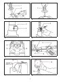
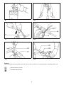
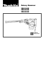
Rotary Hammer
HR3520B
HR3850B
HR3850K
DOUBLE
INSULATION
SPECIFICATIONS
Model
HR3520B
Capacities
Tungsten-carbide bit ....................................................................... 35 mm
Core bit ........................................................................................... 79 mm
No load speed (min–1) ....................................................................... 440
Blows per min. ................................................................................... 3,300
Overall length .................................................................................... 400 mm
Net weight .......................................................................................... 5.8 kg
HR3850B
HR3850K
38 mm
118 mm
240
2,900
442 mm
7.5 kg
38 mm
118 mm
240
2,900
455 mm
7.5 kg
• Due to our continuing program of research and development, the specifications herein are subject to change
without notice.
• Note: Specifications may differ from country to country.
Power supply
The tool should be connected only to a power supply of the same voltage as indicated on the nameplate, and
can only be operated on single-phase AC supply. They are double-insulated in accordance with European
Standard and can, therefore, also be used from sockets without earth wire.
For European countries only
Noise and Vibration of Model HR3520B
EC-DECLARATION OF CONFORMITY
The typical A-weighted noise levels are
sound pressure level: 95 dB (A)
sound power level: 108 dB (A)
– Wear ear protection. –
The typical weighted root mean square acceleration
value is 8 m/s2.
The undersigned, Yasuhiko Kanzaki, authorized by
Makita Corporation, 3-11-8 Sumiyoshi-Cho, Anjo,
Aichi, 446-8502 Japan declares that this product
(Serial No. : series production)
manufactured by Makita Corporation in Japan is in
compliance with the following standards or standardized documents,
HD400, EN50144, EN55014, EN61000
in accordance with Council Directives, 73/23/EEC,
89/336/EEC and 98/37/EC.
Noise and Vibration of Model HR3850B
The typical A-weighted noise levels are
sound pressure level: 94 dB (A)
sound power level: 107 dB (A)
– Wear ear protection. –
The typical weighted root mean square acceleration
value is 12 m/s2.
Yasuhiko Kanzaki CE 94
Noise and Vibration of Model HR3850K
The typical A-weighted noise levels are
sound pressure level: 94 dB (A)
sound power level: 107 dB (A)
– Wear ear protection. –
The typical weighted root mean square acceleration
value is 12 m/s2.
Director
MAKITA INTERNATIONAL EUROPE LTD.
Michigan Drive, Tongwell, Milton Keynes,
Bucks MK15 8JD, ENGLAND
2
1
2
3
4
5
6
7
8
3
9
10
11
12
13
14
Symbols
The following show the symbols used for the tool. Be sure that you understand their meaning before use.
[ Read instruction manual.
[ DOUBLE INSULATION
4
ENGLISH
1
2
3
4
5
6
7
8
Side grip
Grip base
Red dot (Tool holder)
Red dot (Tool retainer)
Tool retainer
Press in
Turn 180°
Change lever
Explanation of general view
9
10
11
12
13
14
15
16
For rotation with hammering
For hammering only
Wing bolt
Depth gauge
Switch trigger
Core bit
Adapter
Center bit
17
18
19
20
21
22
23
24
Rod
Hex wrench
Rear cover
Screwdriver
Brush holder cap
Lock nut wrench
Crank cap
Hammer grease
12. Secure work
Use clamps or a vise to hold work. It’s safer than
using your hand and it frees both hands to operate
tool.
13. Don’t overreach
Keep proper footing and balance at all times.
14. Maintain tools with care
Keep tools sharp and clean for better and safer
performance. Follow instructions for lubricating
and changing accessories. Inspect tool cords
periodically and, if damaged, have repaired by
authorized service facility. Inspect extension cords
periodically and replace if damaged. Keep
handles dry, clean and free from oil and grease.
15. Disconnect tools
When not in use, before servicing, and when
changing accessories such as blades, bits and
cutters.
16. Remove adjusting keys and wrenches
Form the habit of checking to see that keys and
adjusting wrenches are removed from tool before
turning it on.
17. Avoid unintentional starting
Don’t carry plugged-in tool with finger on switch.
Be sure switch is off when plugging in.
18. Outdoor use extension cords
When tool is used outdoors, use only extension
cords intended for use outdoors and so marked.
19. Stay alert
Watch what you are doing. Use common sense.
Do not operate tool when you are tired.
20. Check damaged parts
Before further use of the tool, a guard or other part
that is damaged should be carefully checked to
determine that it will operate properly and perform
its intended function. Check for alignment of moving parts, binding of moving parts, breakage of
parts, mounting, and any other conditions that
may affect its operation. A guard or other part that
is damaged should be properly repaired or
replaced by an authorized service center unless
otherwise indicated elsewhere in this instruction
manual. Have defective switches replaced by and
authorized service center. Do not use tool if switch
does not turn it on and off.
21. Warning
The use of any other accessory or attachment
other than recommended in this operating instruction or the catalog may present a risk of personal
injury.
SAFETY INSTRUCTIONS
Warning! When using electric tools, basic safety
precautions should always be followed to reduce
the risk of fire, electric shock and personal injury,
including the following.
Read all these instructions before attempting to
operate this product and save these instructions.
For safe operation:
1. Keep work area clean
Cluttered areas and benches invite injuries.
2. Consider work area environment
Don’t expose power tools to rain. Don’t use power
tools in damp or wet locations. Keep work area
well lit. Don’t use power tools in presence of
flammable liquids or gases.
3. Guard against electric shock
Prevent body contact with grounded surfaces
(e.g. pipes, radiators, ranges, refrigerators).
4. Keep children away
Do not let visitors contact tool or extension cord.
All visitors should be kept away from work area.
5. Store idle tools
When not in use, tools should be stored in dry,
high, or locked-up place, out of the reach of
children.
6. Don’t force tool
It will do the job better and safer at the rate for
which it was intended.
7. Use right tool
Don’t force small tools or attachments to do the
job of a heavy duty tool. Don’t use tools for
purposes not intended; for example, don’t use
circular saw for cutting tree limbs or logs.
8. Dress properly
Do not wear loose clothing or jewelry. They can be
caught in moving parts. Rubber gloves and nonskid footwear are recommended when working
outdoors. Wear protective hair covering to contain
long hair.
9. Use safety glasses and hearing protection
Also use face or dust mask if cutting operation is
dusty.
10. Connect dust extraction equipment
If devices are provided for the connection of dust
extraction and collection facilities, ensure these
are connected and properly used.
11. Don’t abuse cord
Never carry tool by cord or yank it to disconnect it
from receptacle. Keep cord from heat, oil and
sharp edges.
5
Installing or removing drill bit or other bits
(bull point, etc.) (Fig. 3 & 4)
22. Have your tool repaired by an expert
This electric appliance is in accordance with the
relevant safety rules. Repairing of electric appliances may be carried out only by experts otherwise it may cause considerable danger for the
user.
Important:
Always be sure that the tool is switched off and
unplugged before installing or removing the bit.
Press in the tool retainer and turn it until the red dots
on the tool retainer and the tool holder are aligned.
Release the tool retainer. (Fig. 3)
ADDITIONAL SAFETY RULES
1. Wear a hard hat (safety helmet), safety glasses
and/or face shield. It is also highly recommended that you wear a dust mask, ear protectors and thickly padded gloves.
2. Be sure the bit is secured in place before
operation.
3. Under normal operation, the tool is designed
to produce vibration. The screws can come
loose easily, causing a breakdown or accident.
Check tightness of screws carefully before
operation.
4. In cold weather or when the tool has not been
used for a long time, let the tool warm up for
several minutes by operating it under no load.
This will loosen up the lubrication. Without
proper warm-up, hammering operation is difficult.
5. Always be sure you have a firm footing.
Be sure no one is below when using the tool in
high locations.
6. Hold the tool firmly with both hands.
7. Keep hands away from moving parts.
8. Do not leave the tool running. Operate the tool
only when hand-held.
9. Do not point the tool at any one in the area
when operating. The bit could fly out and
injure someone seriously.
10. When drilling or chipping into walls, floors or
wherever “live” electrical wires may be
encountered, DO NOT TOUCH ANY METAL
PARTS OF THE TOOL!
Hold the tool by the insulated grasping surfaces to prevent electric shock if you drill or
chip into a “live” wire.
11. Do not touch the bit or parts close to the bit
immediately after operation; they may be
extremely hot and could burn your skin.
Insert the bit into the tool holder as far as it will go.
Press in the tool retainer and turn it a full 180 degrees.
Then release it to secure the bit. (Fig. 4)
CAUTION:
Never use A-type shank bits. They can cause damage
to the tool.
To remove the bit, follow the installation procedure in
reverse.
Selecting action mode (Fig. 5)
(Not available for HR3520B)
Rotation with hammering:
For drilling in concrete, masonry, etc., rotate the
change lever to the
position.
Hammering only:
For chipping, scaling or demolition operations, rotate
the change lever to the position.
CAUTION:
• Do not rotate the change lever when the tool is
running under load. The tool will be damaged.
• To avoid rapid wear on the mode change mechanism, be sure that the change lever is always
positively located in one of the two action mode
positions.
Adjusting depth of drilling (Fig. 6)
Loosen the wing bolt and adjust the depth gauge to
the desired depth. After adjusting, tighten the wing
bolt.
Switch action (Fig. 7)
SAVE THESE INSTRUCTIONS.
CAUTION:
• Before plugging in the tool, always check to see that
the switch trigger actuates properly and returns to
the “OFF” position when released.
• Do not tape, tie or otherwise secure the trigger in
the “ON” position.
OPERATING INSTRUCTIONS
Side grip (auxiliary handle) (Fig. 1 & 2)
For maximum control and safer operation, always use
the side grip with this tool. The side grip swings
around to either side, allowing easy handling of the
tool in any position. Loosen the side grip by turning it
counterclockwise, swing it to the desired position and
then tighten it by turning clockwise. (Fig. 1)
To start the tool, simply pull the trigger. Release the
trigger to stop.
The side grip can also be installed in the position
shown in Fig. 2. Remove the side grip from the grip
base by turning the side grip counterclockwise. Screw
the side grip on either side of the tool, whichever is
convenient.
6
Hammer drilling operation
MAINTENANCE
Position the bit at the location for the hole, then pull
the trigger.
Do not force the tool. Light pressure gives best
results. Keep the tool in position and prevent it from
slipping away from the hole.
Do not apply more pressure when the hole becomes
clogged with chips or particles. Instead, run the tool at
an idle, then remove from the hole. By repeating this
several times, the hole will be cleaned out.
CAUTION:
Always be sure that the tool is switched off and
unplugged before carrying out any work on the tool.
Replacement of carbon brushes (Fig. 12 & 13)
Whenever carbon brushes must be replaced, they cut
out the tool automatically. When this occurs, replace
both carbon brushes at the same time. Use only
identical carbon brushes.
CAUTION:
When the bit begins to break through concrete or if
the bit strikes reinforcing rods embedded in concrete,
the tool may react dangerously. Maintain good balance and safe footing while holding the tool firmly with
both hands to prevent dangerous reaction.
Lubrication (Fig. 14 & 15)
This tool requires no hourly or daily lubrication
because it has a grease-packed lubrication system.
Lubricate the tool every time the carbon brushes are
replaced.
Run the tool for several minutes to warm it up. Switch
off and unplug the tool. Remove the crank cap using
a Makita lock nut wrench 35 (optional accessory).
Rest the tool on the table with the bit end pointing
upwards. This will allow the old grease to collect
inside the crank housing. Wipe out the old grease
inside and replace with a fresh grease (60 g). Use
only Makita genuine grease (optional accessory).
Filling with more than the specified amount of grease
(approx. 60 g) can cause faulty hammering action or
tool failure. Fill only with the specified amount of
grease. Reinstall the crank cap and tighten with the
lock nut wrench. Do not tighten the crank cap excessively. It is made of resin and is subject to breakage.
Chipping / Scaling / Demolition
Hold the tool firmly with both hands. Turn the tool on
and apply slight pressure on the tool so that the tool
will not bounce around, uncontrolled. Pressing very
hard on the tool will not increase the efficiency.
Core bit (optional accessory)
When using the center bit
Screw the core bit on the adapter. Install the adapter
with the core bit in the tool in the same manner as a
drill bit. (Fig. 8)
Install the center bit. (Fig. 9)
Rest the core bit on the concrete and turn the tool on.
Once the core bit has cut a shallow groove into the
concrete, remove the center bit. Then resume drilling.
To maintain product safety and reliability, repairs,
maintenance or adjustment should be carried out by a
Makita Authorized Service Center.
To remove the core bit, follow the procedures (1)
or (2).
(1) Rotate the change lever to the position. Then
rest the core bit on the concrete and turn the tool
on. The core bit will come loose from the hammering action. (Fig. 10)
(2) Hold the adapter with the wrench, insert the rod
(optional accessory) into the hole in the core bit
and tap with a hammer to unscrew. (Fig. 11)
When not using the center bit
Screw the core bit on the adapter. Install the adapter
with the core bit in the tool in the same manner as a
drill bit. (Fig. 8)
Rotate the change lever to the position. Rest the
core bit on the concrete and turn the tool on. Once the
core bit has cut a shallow groove into the concrete,
rotate the change lever to the
position and resume
drilling.
NOTE:
No problem is caused even if the core bit unscrews
slightly during brief use since the core bit rotates in
the tightening direction.
To remove the core bit, follow the same removal
procedures covered in When using the center bit.
7
Made in Japan
883660H1