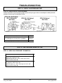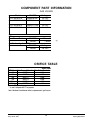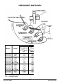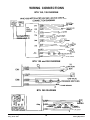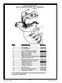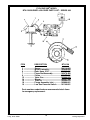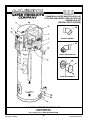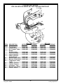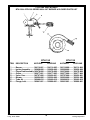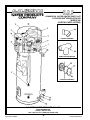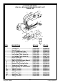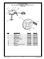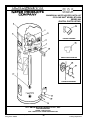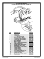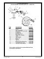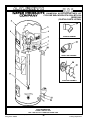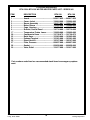
1
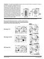
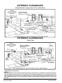
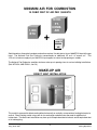
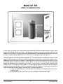
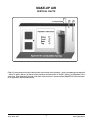
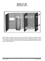
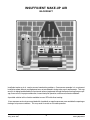
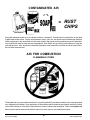
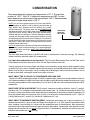
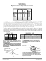
BTH 120, 150, 199, 250
Service Handbook
Includes Parts List For
Series 960 through 967
This Service Handbook was prepared by:
The Training Department
Irving, Texas
$15.00 Printed in the U.S.A. 3 00
Part No. TC-044R2
BTH HANDBOOK
TABLE OF CONTENTS
PAGE
PAGE
Introduction. .................................. 2
Troubleshooting - continued
Pressure Switch Continuity .......... 27-28
Voltage Test - Igniter .................... 29
250 Blower Test ........................... 29
Gas Pressure Test ....................... 30
Installation
Clearances.................................. 3-4
Air Requirements ........................ 5-9
Contaminated Air ........................ 10
Flammable .................................. 10
Condensation .............................. 11
Venting ........................................ 12
Tables
Component Part .......................... 31
Orifice Tables .............................. 31
Pressure Switches ...................... 32
Sequence of Operation
Mechanical .................................. 13
Wiring Schematics
Natural and Propane Gas ............ 33
Information
Multiple Unit Piping ...................... 14
Controls ...................................... 15-17
Service Aids. ................................. 34
General Questions & Answers. .... 35
Error Codes ................................... 36
Troubleshooting
Pre-Service ................................. 18
Igniter Continuity Check ............... 18-19
Control Board Check ................... 20
Transformer ................................. 21-22
Control Board .............................. 22-23
Temperature ................................ 24
Blower ......................................... 25-26
A. O. Smith Water Products Company
Irving, Texas 2000©
Service Checklist .......................... 37
Parts Lists
966 & 967 Series ........................ 38-49
960 Series .................................. 50-53
962 Series .................................. 54-61
1
Service Handbook
Training Department
BTH HANDBOOK INTRODUCTION
This service handbook is designed to aid in servicing and troubleshooting A. O. Smith BTH water
heaters in the field. No duplication or reproduction of this book may be made without the express
written authorization of the A. O. Smith Water Products Company.
The following text and illustrations will provide you with a step by step procedure to verify proper
installation, operation and troubleshooting procedures. Additional quick reference data is included to
assist you in servicing this product.
The information contained in this handbook is designed to answer commonly faced situations encountered in the operation of the BTH product line and is not meant to be all inclusive. If you are
experiencing a problem not covered in this handbook, please contact the A. O. Smith Technical
Information Department at 1-800-527-1953 or your local A. O. Smith Water Products company
representative for further assistance. This handbook is intended for use by licensed plumbing
professionals and reference should be made to the instruction manual accompanying the product.
This handbook contains supplemental information to the BTH instruction manual.
Qualifications: Installation or service of this water heater requires ability equivalent to that of a
licensed tradesman in the field involved. Plumbing, venting, gas supply and electrical testing skills are
required.
Tools Required:
• Phillips head screw driver
• Flat tip screw drivers
• Set of marked drill bits
• Electric multimeter tester
• Gas pressure gauge or manometer (gauge - AOS part number 8099-2)
• Water pressure gauge (AOS part number 4798)
• Draft gauge
• Thermometer (AOS part number 4870 - range 0 thru 220°F)
• 1/2 inch socket with extension for removal of the cleanout
• 1 1/8 inch socket for removal of the anode
• 1 inch socket for hot surface igniter removal
• Pipe wrench for union disconnect
*Note: Also, have a copy of the instruction manual for the model and series BTH
that you are servicing.
Revision 2 includes an added Multiple Venting statement on page 3 and a new Blower Motor Ohms
Resistance Table on page 25. The Pressure Switch Table on page 32 was expanded/revised.
A. O. Smith Water Products Company
Irving, Texas 2000©
2
Service Handbook
Training Department
Installation: This portion of the handbook will review often overlooked installation considerations, taking note
of necessary instruction requirements for the
BTH 120 - 250 / 966 and 967 Series. The installation manual covers most of these items in detail. BTH heaters are approved for installation on
combustible flooring. Most can be installed in an
alcove with minimum clearances to combustibles
or non-combustibles of 0 inches from the sides
and rear, 0 inches from vent piping, and 1.5 inches
from the top cover. A 24 inch clearance for all
serviceable parts is recommended. Clearances
may vary between BTH models. See instruction
manual or the label on the heater for clearances
applicable to your specific model.
This illustrates the exterior clearances for these BTH units when installed as direct vent heaters.
Note: 24 inches between inlet and outlet is a minimum. Greater distance is
recommended. In colder climates increasing the 24" minimum to a maximum
practical distance, will reduce the possibility of frost over from side winds blowing exhaust vapors to the air intake of the direct vent.
BTH Model 120
BTH Model 150-199
BTH Model 250
A. O. Smith Water Products Company
Irving, Texas 2000©
3
Service Handbook
Training Department
EXTERIOR CLEARANCES
Horizontal Vent (using room air for combustion)
WarningVent Hood(s) May Be
Extremely Hot During
Operation
Vent Hood Must Be
Mounted 4' Minimum
Below Doors and Windows
4' Minimum
Exhaust
4' Minimum
Regulator
3' Min.
Exhaust
4' Minimum
3' Above Any Forced
Air Intake Within 10'
Gas
Meter
Exhaust
Exhaust
Vent Hood Must Be
Mounted 4' Minimum
Below Windows
Vent Hood Must Be
Mounted 1' Minimum
Below Windows
3' Minimum
From
Inside Corner
Recommended
1' Above
Grade*
*Recommended Clearance of 1' Above "Anticipated Snow Level" Where Applicable
EXTERIOR CLEARANCES
Direct Vent
WarningVent Hood(s) May Be
Extremely Hot During
Operation
Exhaust
Regulator
Air
intake
(optional)
Vent Hood Must Be
Mounted 9" Minimum
Above Doors
and Windows
Minimum
Intake
3' Min.
Exhaust
Intake
3' Above Any Forced
Air Intake Within 10'
Gas
Meter
Exhaust
Intake
Exhaust Intake
Vent Hood Must Be
Mounted 1' Away
Horizontally From Doors
and Windows
Intake Air Must Be
Mounted 1' Minimum
Below Windows
Exhaust 4"
3' Minimum From
Inside Corner
Recommended
1' Above
Grade*
*Recommended Clearance of 1' Above "Anticipated Snow Level" Where Applicable
When multiple units are direct vented through a wall, all intake vent terminals must be no lower than the
highest exhaust vent terminal.
CAUTION
DO NOT TERMINATE THE VENTING WHERE NOISE FROM THE EXHAUST OF INTAKE WILL BE OBJECTIONABLE.
THIS INCLUDES LOCATIONS CLOSE TO OR ACROSS FROM WINDOWS AND DOORS. AVOID ANCHORING THE
VENT AND INTAKE PIPES DIRECTLY TO FRAMED WALLS, FLOORS OR CEILINGS UNLESS RUBBER ISOLATION
PIPE HANGERS ARE USED. THIS PREVENTS ANY VIBRATIONS FROM BEING TRANSMITTED INTO THE LIVING
SPACES.
A. O. Smith Water Products Company
Irving, Texas 2000©
4
Service Handbook
Training Department
MINIMUM AIR FOR COMBUSTION
10 CUBIC FEET OF AIR PER 1,000 BTU
1,000
BTU
10 CU.
FT.
COMB.
AIR
+
2.5 CU. FT.
EXCESS
AIR
Stoichiometric or theoretical complete combustion requires 10 cubic feet of air per 1000 BTUH input of the gas
input. The National Fuel Gas Code also recommends an additional 2.5 cu.ft. of "excess air". This
12.5 cu.ft. minimum supply air per 100 BTUH input applies to natural and propane gas models.
The National Fuel Code also specifies minimum make-up air opening sizes for various building installations.
(Ref: NFPA 54, ANSI Z223.1, sec 5.3).
MAKE-UP AIR
DIRECT VENT INSTALLATION
This model is approved for direct venting either horizontally or vertically or conventional venting horizontal or
vertical. Direct venting avoids using room air for combustion and eliminates the need for additional air
intake ducts. The direct vent installation may have up to 50 equivalent feet of exhaust and 50 equivalent feet
of air intake piping
A. O. Smith Water Products Company
Irving, Texas 2000©
5
Service Handbook
Training Department
MAKE-UP AIR
DIRECT COMMUNICATION
A fresh supply of make-up air for combustion can be supplied to the heater through make-up air ducts, which
directly communicate with the out of doors. Two openings are required - one within 12 inches of the top of the
enclosure and one within 12 inches of the bottom of the enclosure. Each opening shall have a free area of not
less than 1 square inch per 4000 BTUH of the total input of all appliances within the enclosure.
The lower opening is primarily providing combustion air. The upper opening is providing vent dilution air and
acts as a relief opening for flue gases should the vent become obstructed or a down draft condition occur.
Additionally, when the heater is installed in a confined space and communicating with the outdoor air, one
permanent opening, commencing within 12 inches (30 cm.) of the top of the enclosure, shall be permitted
where the equipment has clearances of at least 1 inch (2.5 cm.) from the sides and back and
6 inches (16 cm.) from the front of the appliance. The opening shall directly communicate with the outdoors
and shall communicate through a vertical or horizontal duct to the outdoors or spaces (crawl or attic) that
freely communicate with the outdoors, and shall have a minimum free area of:
a. 1 sq. in. per 3000 BTU per hr (7 cm2 per kW) of the total input of all equipment located in the
enclosure, and
b. Not less then the sum of the areas of all vent connectors in the confined space.
A. O. Smith Water Products Company
Irving, Texas 2000©
6
Service Handbook
Training Department
MAKE-UP AIR
VERTICAL DUCTS
Often it is more practical to install vertical make-up air ducts to the out doors. Again, two openings are required
- within 12 inches (30 cm.) of the top of the enclosure and one within 12 inches (30 cm.) of the bottom of the
enclosure. Each opening shall have a free area of not less than 1 square inch per 4000 BTUH of the total input
of all appliances within the enclosure.
A. O. Smith Water Products Company
Irving, Texas 2000©
7
Service Handbook
Training Department
MAKE-UP AIR
HORIZONTAL DUCTS
r
h Ai
Fres
r
h Ai
s
e
r
F
When the heater is installed in an interior room with no roof access for vertical ducts, horizontal make-up
ducts should be installed. When using horizontal ducts, two openings are required - within
12 inches (30 cm.) of the top of the enclosure and one within 12 inches (30 cm.) of the bottom of the enclosure. Each opening shall have a free area of not less than 1 square inch per 2000 BTUH of the total input of all
appliances within the enclosure.
A. O. Smith Water Products Company
Irving, Texas 2000©
8
Service Handbook
Training Department
INSUFFICIENT MAKE-UP AIR
BACKDRAFT
Insufficient make-up air is a major cause of combustion problems. One common example is in a restaurant
installation where exhaust vent equipment was not considered in sizing make-up air requirements. This may
result in air being backdrafted by the restaurant exhaust equipment through the heater causing flue gas spillage, flame roll out, improper combustion, inconsistent pilot operation, and/or erratic heater shutdown.
A possible solution to this situation would be to use a BTH with direct venting.
A less common service issue associated with a backdraft or negative pressure room would be the opening or
closing of air pressure switches. This may result in erratic or no heater operation.
A. O. Smith Water Products Company
Irving, Texas 2000©
9
Service Handbook
Training Department
CONTAMINATED AIR
= RUST
CHIPS
Along with adequate make-up air, the quality of the air is important. Contaminants in combustion air can lead
to premature heater failure. Vapors from bleaches, soaps, salts, etc. are drawn into the combustion chamber
with the make up air and, once fired, mix with water vapor in the gasses to form extremely corrosive hydrochloric or hydrofluoric acid an other corrosive byproducts. Dust drawn in may build up on the blower or clog the
main burner ports. Also, be certain to examine the exterior area around the air intake of a direct vent installation for these contaminants.
AIR FOR COMBUSTION
FLAMMABLE ITEMS
Flammable items or pressurized containers or any other potentially hazardous articles must never be placed
on or adjacent to the heater. Open containers of flammable material should not be stored or used in the same
room with the heater or in the area of the exterior air intake of a direct vent installation. Direct venting does not
eliminate the need to remove flammable or corrosives from the area surrounding the heater.
A. O. Smith Water Products Company
Irving, Texas 2000©
10
Service Handbook
Training Department
CONDENSATION
The average dewpoint of natural gas flue products is 127 °F. Propane flue
products is 119° F. With 70° F ambient air temperature and 180° F stored
water temperature, exhaust gas will be approximately 140° F. Recommended
safe water storage temperature is 120° F.
NOTE: This unit can be vented using only PVC (Class 160, ASTM D2241; Schedule 40, ASTM D-1785; or Cellular Core Schedule 40
DWV, ASTM F-891), Schedule 40 CPVC (ASTM F-411), or ABS
(ASTM D-2661) pipe. The fittings, other than the TERMINATIONS
should be equivalent to PVC-DWV fittings meeting ASTM D-2665
(Use CPVC fittings, ASTM F-438 for CPVC pipe and ABS fittings,
ASTM D-2661/3311 for ABS pipe. If CPVC or ABS pipe and fittings
are used, then the proper cement must be used for all joints, including
joining the pipe to the Termination Tee (PVC Material). PVC Materials
should use ASTM D-2564 Grade Cement; CPVC Materials should
use ASTM F-493 Grade Cement and; ABS Materials should use
ASTM D-2235 Grade Cement.
NOTE: for Water heaters in locations with high ambient temperatures
(above 100°F) and/or insufficient dilution air, it is recommended that
CPVC or ABS pipe and fittings (MUST USE SUPPLIED VENT
TERMINAL) be used.
CONDENSATE
DRAIN HOSE
MUST DRAIN.
The extra high thermal efficiency of the BTH will result in condensation in the flue passage. The following
answers common questions about this condensation.
Can I drain this condensation to the floor drain? The "Corrosion Resistance of Cast Iron Soil Pipe" by the
Ductile Metals Association (formally the Cast Iron Soil Pipe Institute) states that:
"Internal corrosion of cast iron soil pipe and fittings can be caused by strong acids or other reagents having
an acidity of pH 4.3 or less if allowed to contact cast iron pipe for an extended period of time without sufficient
dilution to raise the pH valve about 4.3. By avoiding low pH discharges, internal corrosion problems can be
limited or eliminated, assuring the owner many years of service."
WHAT ABOUT THE Ph VALUES OF CONDENSATE AND SODA POP?
The pH of the BTH condensate average 4.5 which is approximately 4 times less concentrated than the limit
of 4.3 recommended by the DMA. Any water flow in the drain rapidly dilutes the condensate even more. A can
of leading carbonated cola drink measured a pH of 2.5 which is 300 times more condentrated than the BTH
condensate.
WHAT DOES THE Ph SCALE MEAN? The PH value is a measure of acidity or alkalinity. A pH of 7 is neutral.
Numbers from 7 to 1 indicate increasing acidity and numbers from 7 to 14 indicate increasing alkalinity. The
pH scale is similar to the Richter scale used to measure earthquakes. Each number indicates a change of 10
times the concentration of the previous value. A pH-6 is 10 times more concentrated than a pH-7, a pH-5 is
(10x10) 100 times pH-7 and pH-4 is (10x10x10) 1,000 times pH-7, etc.
WHAT ABOUT CONDENSATE NEUTRALIZERS? Condensate neutralizers are usually not necessary. A
condensate neutralizer is easy to make by filling a short length of 2" or 3" PVC pipe with landscape marble
chips, capping it and installing it in series with the condensate drain of the equipment. Most commercial
neutralizers are off the market because of poor demand for the product. Condensation from the exhaust vent
piping and tank internal flue way must be allowed to drain. A "blocked flue" indication will often be your first
indication that condensate is not draining.
A. O. Smith Water Products Company
Irving, Texas 2000©
11
Service Handbook
Training Department
VENTING
Equivalent Feet of Pipe Intake or Exhaust
VENT LENGTH TABLE
Number of
90° Elbows
One (1)
Two (2)
Three (3)
Four (4)
Five (5)
Six (6)
4"
Maximum
3"
Pipe
3" Minimum Maximum
Pipe (Feet) Pipe (Feet)
(Feet)
7
45
115
7
40
110
7
35
105
7
30
100
-7
95
-7
90
4-inch PVC may be used for a MAXIMUM intake of ONE HUNDRED TWENTY (120) EQUIVALENT FEET
and a MAXIMUM exhaust of ONE HUNDRED TWENTY (120) EQUIVALENT FEET. The maximum number
of 90° elbows with the 4-inch venting is six (6) on the intake and six (6) on the exhaust. A 90° elbow is equal
to five (5) equivalent feet of pipe. One (1) 90° elbow is equal to two (2) 45° elbows. Any venting configuration
using less than 50 equivalent feet should use 3-inch venting. See Vent Length Table.
The 3-inch venting terminals (provided) must be used with the 4-inch venting by adding 4 x 3 reducing
couplings at the venting terminals. A reducing coupling is also needed immediately after the condensate
elbow (exhaust) and immediately before the 3-inch blower adapter (intake) if direct venting is installed. See
Vent Length Table.
SUPPLY GAS
Minimum Maximum
Inches
Inches
Gas Type
W.C.
W.C.
Natural
5
10.5
Propane
11
13.8
MANIFOLD GAS
Gas Type
Natural
Propane
NOTE: Pressure without capacity will result in
lockout. Follow the piping guidelines in the
instruction manual.
The supply gas pressure in normally measured
at the dirt leg or at the inlet gas pressure tapping
on the gas valve. This reading must be measured
with 'flowing' gas.
Minimum/Maximum
Inches W.C.150/199
3.5
10
Minimum/Maximum
Inches W.C. 120/250
4.0
10.0
The manifold gas pressure is measured at the
manifold pressure tap of the gas valve when the
gas is flowing.
Pressure Regulator Adjustment
(Cover Screw)
Regulated Gas Supply
Line
Main Gas Shutoff Valve
Gas Valve On/Off
Inlet Pressure Tap
TH & TR Terminals
(Main Valve)
Gas Inlet
Manifold
Pressure Tap
Gas Outlet
Dirt Leg Tee
Pipe Cap
A. O. Smith Water Products Company
Irving, Texas 2000©
The gas valves used on all BTH water heaters are
24 volt AC combination step opening gas valves.
They incorporate the main valve, and gas pressure
regulators into one body.
12
Service Handbook
Training Department
BTH Sequence of Operation
Power Off
Display Sequence
Power On
If ECO is closed low
gas pressure switch
is closed
(120 & 250
models only)
Display "00"
Call for heat (Temp.
setting less diff.)
Supply Volts
"120"
Blower Prepurge
20 Seconds
Pressure Switch Information
Blocked Inlet-NC
Opens .75" wc
Neg. Press
BTH 120 and 250
Only
Low Supply Gas
Pressure
Switch NC 4.3"
w.c. gas
press. to close
Blocked Outlet-NC
Opens at 2.5"
Positive Press
Blower Prover
Closes at .45"
Positive Press
Draft Prover
Switches to
Proper State
HSI is Energized
Blower speed
reduces BTH 250
only
If reset is pushed
and released while
this is displayed, the
board will do an
operational self
check.
Temperature
Offset 12%
Weighted Average
Tank Termpature
Bottom vs Top
Igniter
warm-up period
Pushing the reset at
this time will display
tank temp. setting.
Push once and hold
to increase setting.
Push twice and hold
to decrease settings
110°-180°
Gas Valve Opens
Blower to Full RPM
BTH-250 only
7.5 Sec Trial
for ignition
NO
YES
Flame Rod Does
Not Prove Flame
Flame Rod Senses
Flame .7 microamp
minimum
Tank Water Heated
to Set Point
30 Second
Purge
Gas Valve Closes
Retry-Max
3 times
30 Sec Post Purge
Display Failure Code
Note: If the lower temperature probe is defective or unplugged, display will show upper tank
temperature. Heater may fire but stack.
If upper high limit/tank temp. thermistor is defective or disconnected, cycling power off then on
displays will be: 00, 120, 12, water temp at lower probe, flashing "04" code.
A. O. Smith Water Products Company
Irving, Texas 2000©
13
Service Handbook
Training Department
MULTIPLE UNIT - WATER PIPING
PARALLEL PIPING
HOT TO FIXTURES
REVERSE RETURN PIPING
2"
1 1/2"
RETURN
COLD
EXHAUST
VENT TO
OUTDOORS
2"
PUMP
NOTES APPLY TO ALL SYSTEMS:
*ADD GATE VALVES TO INLET AND OUTLET OF EACH UNIT
FOR ISOLATION FLEXIBILITY. LOCATE AT THE SAME POINT
FROM TEE.
CHECK
VALVE
** ADD THERMAL EXPANSION TANK TO COLD WATER
SUPPLY IF NECESSARY.
PARALLEL PIPING WITH TANK
CONDENSATION HOSE MUST BE ALLOWED TO DRAIN.
NOTE: T&P VALVES MUST BE PIPED TO OPEN DRAIN OR
PER LOCAL CODE.
T&P VALVE
REVERSE RETURN PIPING
WITH TANK
T&P
1 1/2"
PIPE TO OPEN
DRAIN
1 1/2"
2"
HOT
TANK
THERMOMETER
COLD
SUPPLY
COLD
RETURN
PUMP
CIRCULATOR THERMOSTAT
SET 5° COOLER THAN
HEATER SETTINGS
2"
CHECK
VALVE
1 1/2"
RETURN
2"
1 1/2"
A. O. Smith Water Products Company
Irving, Texas 2000©
14
Service Handbook
Training Department
CYCLONE BTH
NORMAL INDICATIONS / READINGS
DURING CALL FOR HEAT
Tank temperature below control setting
(to check control setting, press reset button)
• On/off switch “on”
Note: Power must be on at least 4 seconds before reset can be pressed to indicate control setting.
•
•
•
•
•
•
•
•
•
•
Control panel indication lights “on”
On/off switch light “on”
120 VAC
24 VAC
High limit
Blower fan (while fan is running)
Pressure switch (while blower is running)
Control status
Thermostat “on”
Gas valve (during 4 second trial for ignition and while
burner is on)
• Current average tank water temperature displayed
A. O. Smith Water Products Company
Irving, Texas 2000©
15
DISPLAY PANEL (CONTROL PANEL)
Service Handbook
Training Department
CYCLONE BTH
NORMAL INDICATIONS / READINGS
120 VAC present to ground and:
• Each black terminal of on/off switch
• CN1 black term 1
• CN 2 black term 1
• CN 4 black term 1
• CN 5 white term 1 (only while ignitor is heating)
Note: CN 6 black term 2 will give reading of 90-100 volts – ignore
this reading.
24 VAC present to ground and:
• CN 3 red term 1 and red term 4
• CN 4 blue term 4
• CN 6 blue term 3, brown term 4, and brown term 6
• Each terminal of the 3 or 4 pressure switches
A. O. Smith Water Products Company
Irving, Texas 2000©
16
Service Handbook
Training Department
NORMAL INDICATIONS / READINGS
AFTER TANK IS SATISFIED
Tank temperature above control setting
• On/off switch is “on”
Normal conditions will be 120 volts present to ground and:
• Each black terminal of on/off switch
• CN 1 black term 1
• CN 4 black term 1
Note: CN 6 black term 2 (flame sensor) may display 90-100 VAC – this is a non-reading, ignore it
24 VAC present to ground and:
• CN 3 red term 1 and red term 4
• CN 4 blue term 4
• CN 6 brown term 4
• Blocked inlet switch – each terminal (tube connects to inlet of blower)
• Blower prover switch – upper terminal (this is the jumper wire from the blocked inlet switch)
Control panel indication light “on”
• On/off switch light
• 120 VAC
• 24 VAC
• High limit
• Control status
• Current (average) tank temperature will be displayed
(BTH 120, 250 Only)
A. O. Smith Water Products Company
Irving, Texas 2000©
17
Service Handbook
Training Department
TROUBLESHOOTING
PRE-SERVICE TIPS
CHECK THAT:
• Tank is full of water
• Exhaust and intake vent do not exceed allowable limits
• All plugs into boards are secure
• Condensate hose is drained and open
• 115-120 VAC is supplied to the heater (including polarity
check a neutral to ground check results in "0" volts reading)
• Proper (natural or propane) gas is supplied
CONTINUITY CHECKS
Condition:
After 20 second prepurge is complete
No main burner
•
On/Off switch is off
•
Igniter wires disconnected from CN5
•
Multimeter set to "continuity check"
2000 OHMS scale
STEP 1 - IGNITER CONTINUITY CHECK
Connector from CN5
STEP 1. Check continuity through the leads of the igniter.
IF…
THE
a continuity range of 50-300 ohms is not present
a continuity range of 50-300 ohms is present
rep
rea
A. O. Smith Water Products Company
Irving, Texas 2000©
18
Service Handbook
Training Department
TROUBLESHOOTING
STEP 2 - CHECK CONTINUITY THROUGH THE VALVE COIL
STEP 2. Check Continuity Through The Valve
Coil
•
•
•
•
Power off
Gas valve - coil continuity check
Disconnect wires from gas valve
Multimeter set to scale.
OHMS RESISTANCE TABLE
BTH Model
Gas
OHMS Resistance
120
N
100
150, 199
N
560
150, 199
P
63
250
N
63
IF…
meter does not indicate +/- 7.5% of table
meter indicates +/- 7.5% of table
Usually a defective coil will be indicated by a "0" or "1" on the meter.
A. O. Smith Water Products Company
Irving, Texas 2000©
19
Service Handbook
Training Department
TROUBLESHOOTING
STEP 3 - CONTROL BOARD CHECK
STEP 3. 120 VAC SUPPLIED
TO CONTROL BOARD - CN1
CONNECTION
• Disconnect plug from CN1
terminal
• Power switch "On" - 120 VAC
indicator light should be "On"
Check for 120 VAC black wire
terminal to white wire terminal
on plug.
Volts
IF …
1 2 0 V A C is n o t p re s e n t
1 2 0 V A C is p re s e n t
R e a t t a c h p lu g t o C N 1 t e rm in a l.
A. O. Smith Water Products Company
Irving, Texas 2000©
20
Service Handbook
Training Department
TROUBLESHOOTING
STEP 4 - TRANSFORMER TEST
STEP 4. 120 VAC SUPPLIED TO 24 VAC TRANSFORMER CN4.
• Disconnect CN 4 plug from board
Check for 120 VAC between the black terminal connect and white terminal connect on the control board.
IF…
120 VAC is not present
120 VAC is present
THEN
check CN 1
replace contr
go to Step 5.
Reconnect the plug to CN 4 terminal.
A. O. Smith Water Products Company
Irving, Texas 2000©
21
Service Handbook
Training Department
TROUBLESHOOTING
STEP 5 - 24 VAC FROM TRANSFORMER
STEP 5. 24 VAC FROM TRANSFORMER
24 VAC transformer indicator light should be "on".
Insert probe into back of connect. Check for 24 VAC
blue wire connect to ground and yellow wire connect
to ground.
Meter Should
Read 24 VAC
IF…
blue to ground does not have 24 VAC
blue to ground does have 24 VAC
yellow to ground does have 24 VAC
yellow ground does not have 24 VAC
THEN
replace trans
continue
replace trans
go to Step 6.
STEP 6 - CONTROL BOARD TEST
STEP 6. 24 VAC FROM CONTROL BOARD TERMINAL CN3 TO E.C.O.
Plug to CN 3 disconnected. (Energy Cutoff)
Check for 24 VAC red terminal 4 to ground on CN 3 terminal (red wires are the ECO wires).
A. O. Smith Water Products Company
Irving, Texas 2000©
22
Service Handbook
Training Department
TROUBLESHOOTING
STEP 6. (continued)
IF…
THEN
24 VAC is not present
replace
24 VAC is present
go to St
STEP 7 - TEST FOR 24 VAC THRU ECO
STEP 7. 24 VAC THRU ECO (ECO IS NOT A THERMISTOR).
Reinstalled plug.
Check for 24 VAC from back of red 1 plug to ground.
IF ...
TH E N
24 V A C is not pres ent
replac e
go to s t
24 V A C is pres ent
N ote: R es is tanc e thru E C O - plug red 1 to plug red 4 - is .5 o
A. O. Smith Water Products Company
Irving, Texas 2000©
23
Service Handbook
Training Department
TROUBLESHOOTING
STEP 8 - TEMPERATURE THERMISTOR CHECK
STEP 8. TEMPERATURE THERMISTOR CHECK.
The ohm’s resistance thru a thermistor is interpreted by the control board as a water temperature reading.
• Note tank water temperature on display board or tank a thermometer reading from the T&P valve and
drain valve
• Disconnect plugs from CN 3 and CN 8
• Set multimeter to read “resistance” (20 K scale)
Check the ohm’s resistance from black to black on the CN 3 plug and black to black on the CN 8 plug.
IF…
Ohm reading does not (approximately) correspond
to table information
Ohm reading does correspond (approximately) to
the table information.
Water Temp
°C
°F
3
40
21
70
37.5
100
49
120
54.5
130
60
140
71
160
82
180
OHMS
Resistance
26,435
11,974
5,862
3,780
3,066
2,503
1,698
1,177
THEN
replace
go to St
Note: Thermistors are very reliable unless a wire is cut or
connection loose. A "bad" thermistor temperature sensor is
unlikely to be the problem.
Lower Temperature Probe Plug
Upper Temperature Probe Plug
A. O. Smith Water Products Company
Irving, Texas 2000©
24
Service Handbook
Training Department
TROUBLESHOOTING
STEP 9 - BLOWER SPEED TEST
Reconnect plugs to board.
Blower operation check
• Tank must be calling for heat (minimum setting available is 80 F)
• Set multimeter to read 120 VAC
STEP 9. Check for 120 VAC from the back of CN 2 plug term 1 (black) to ground and from CN 2
term 2 (white) to ground.
He a te r m ode ls Ohm s re sista nce
966 or 967
de sire d +/- 7.5%
BTH 120
11.5
BTH 150 AND 199
11.2
BTH 250
7.4
Note: A shorted blower motor may damage the
control board or, on BTH 250 models, the blower
speed reduction board. Conduct a continuity
check between the black and white terminals of the
C2 blower plug.
IF…
terminal 1 to gnd. does not show 120 VAC
terminal 1 to gnd. does show 120 VAC
AND
blower is not runn
blower is running
A. O. Smith Water Products Company
Irving, Texas 2000©
25
Service Handbook
Training Department
TROUBLESHOOTING
STEP 9A - BLOWER SPEED REDUCTION TEST
BTH 250 ONLY
HAS BLOWER SPEED REDUCTION BOARD
Blower wires (CN 2), igniter wires (CN 5), gas valve pressure switches and flame sense (CN6) plug directly
into blower speed reduction board.
The cables from the blower speed reduction board plug into the control board recepticles CN 2, CN 5, and
CN 6.
• 120 VAC present at CN 2 term 1 to gnd.
• Blower not running
• Tank is calling for heat
STEP 9A. Check for 120 VAC from blower speed reduction board plug (CN 2) term 1 (black wire) to
ground.
IF…
120 VA C is not present
120 VA C is present
THE N
replace the blower s
replace the blower
120 Volts on meter
STEP 9A
*
*Voltage from blower at low speed
will be approximately 80 VAC.
STEP 9B
STEP 9B - BLOWER TEST
STEP 9B.
IF …
THEN
blower runs but does not reduce
replace blower spee
speed during igniter warm up or stops
during igniter warm up
blower operates OK
A. O. Smith Water Products Company
Irving, Texas 2000©
go to Step 10.
26
Service Handbook
Training Department
TROUBLESHOOTING
STEP 10 - CONTINUITY PRESSURE SWITCH TEST - ALL MODELS
Power Off
STEP 10. CONTINUITY CHECK OF EACH PRESSURE SWITCH - TERMINAL TO TERMINAL.
(Meter buzz indicates continuity)
IF…
Block inlet switch does not show continuity
Block inlet switch does show continuity
Blower proving switch does not show continuity
Blower proving switch does show continuity
Low gas pressure switch (BTH 120 and 250 only) does
not show continuity
THEN
replace
continue
continue
replace
check
replac
Low gas pressure switch does show continuity
continue
Blocked outlet pressure switch does not show continuity replace
Blocked outlet pressure switch does show continuity
continue
24 VAC check through pressure switches – blower off.
• Power on
• Tank not calling for heat
• Multimeter set to check for 24 VAC
Note: Power flows from bottom terminal to top terminal of each switch – check wiring
A. O. Smith Water Products Company
Irving, Texas 2000©
27
Service Handbook
Training Department
TROUBLESHOOTING
STEP 11 - 24 VAC CHECK
STEP 11. 24 VAC CHECK –
Each terminal of pressure switch to ground; bottom (B) first then top (T) to ground next.
IF…
blocked inlet (B) to gnd does not have 24 VAC
blocked inlet (B) to gnd does have 24 VAC
blocked inlet (T) to gnd does not have 24 VAC
blocked inlet (T) to gnd does have 24 VAC
blower prover (B) to gnd does not have 24 VAC
blower prover (B) to gnd does have 24 VAC
blower prover (T) to gnd does not have 24 VAC
blower prover (T) to gnd does have 24 VAC
THEN
check w
continue
replace
continue
check w
continue
go to St
replace
STEP 12 - 24 VAC CHECK THROUGH PRESS SWITCHES
STEP 12. CONTINUATION OF 24 VAC CHECK THROUGH PRESS SWITCHES
• Tank calling for heat
• Blower on (See Table on Page 32 for Opening/Closing Pressures).
IF...
blower prover (T) to gnd does not have 24 VAC
blower prover (T) to gnd does have 24 VAC
(BTH 120 and 250 only)
low gas press (B) to gnd does not have 24 VAC
low gas press. (B) to gnd does have 24 VAC
low gas press (T) to gnd does not have 24 VAC
low gas press (T) to gnd does have 24 VAC
blocked outlet (B) to gnd does not have 24 VAC
blocked outlet (B) to gnd does have 24 VAC
blocked outlet (T) to gnd does not have 24 VAC
blocked outlet (T) to gnd does have 24 VAC
A. O. Smith Water Products Company
Irving, Texas 2000©
THEN
• check for pos
• air tubing is c
• replace switc
continue.
check wire con
continue.
• check supply
• connection tu
• replace switc
continue.
• check wire co
• blower prover
• if BTH 120 or
continue.
• check for blo
• check for pos
• replace switc
continue to Ste
28
Service Handbook
Training Department
TROUBLESHOOTING
STEP 13 - VOLTAGE TEST ON 250 MODELS ONLY
STEP 13. VOLTAGE TEST TO IGNITER. HSI PLUG MAY BE REMOVED.
Check for 120 VAC on the control circuit board - plug CN 5, term 1 to ground.
IF…
120 VAC is not present
120 VAC is present
THEN
replace control b
igniter should be
STEP 13
STEP 13A
STEP 13A - BLOWER SPEED CHECK ON 250 MODELS ONLY
STEP 13A. ON BTH 250 MODELS ONLY.
Also check for 120 VAC on the blower speed board - CN 5 term 1 to ground.
(Blower should be at reduced RPM)
IF…
120 VAC is not present
120 VAC is present
blower is not running or is at full RPM
blower is reduced RPM
A. O. Smith Water Products Company
Irving, Texas 2000©
THEN
replace b
continue
replace b
go to Ste
29
Service Handbook
Training Department
TROUBLESHOOTING
STEP 14 - SUPPLY GAS PRESSURE TEST
STEP 14. CHECK SUPPLY GAS PRESSURE
Attach monometer or gas pressure gauge to pressure tap on gas valve or use adapter to check pressure
ahead of valve as near as possible to valve.
BTH 150, 199 Propane
BTH 250 Natural
Gas Valve
BTH 150, 199 Natural
Gas Valve
IF…
supply gas pressure is not between 4.5 and 14"
w.c. natural gas or 11.0 and 14" w.c. propane
THEN
adjust sup
minimum i
proper supply gas pressure is present
go to Step
BTH 120 Natural
Gas Valve
STEP 15 - GAS PRESSURE MANIFOLD TEST
STEP 15. CHECK GAS PRESSURE TO MANIFOLD
IF…
TH
•pressure is not 3.5" w.c. ± 0.2" on natural gas or 10.0" on rep
propane gas on BTH 155, 199
•pressure is not 4.0" w.c. ± 0.2" natural gas or 10.0"
propane on BTH 120 or 250
•pressure is 3.5" w.c. ± 0.2" natural gas or 10.0" w.c. ±
ign
0.2" propane on BTH 155 or 199
•pressure is 4.0" w.c. ± 0.2" natural gas or 10.0" ± 0.3"
propane on BTH 120 or 250
A. O. Smith Water Products Company
Irving, Texas 2000©
30
Service Handbook
Training Department
COMPONENT PART INFORMATION
GAS VALVES
Model
AOS PT#
W.R. 36E36-319
192966-0 Nat.
Hnwl VR8305M-4009 192797-Nat.
Voltage
24 VAC
24 VAC
W.R. 36C68-814
W.R. 36C68-809
24 VAC
24 VAC
192454-1 Prop
1922454-0 Nat.
HSI
Flame Rod
AOS PT#
192478
Hot Surface Igniter (HSI)
AOS PT#
192478
Flame S
.7 Micro
(µ)
Voltage
120 VAC
ORIFICE TABLE
Orifice Table
BTH Model Main Burner Orifice No. Main Orifice Size Inches
199
192477-0
0.304
150
192477-1
0.235
250
192477-2
0.360
120
192477-3
0.204
199 Prop
192477-4
.166*
150 Prop
192477-5
.141*
*-4 and -5 Red plated for propane.
** -4 and -5 stamped with "P" for propane
Note: Hex head of main burner orifice is upstream end - gas flows ou
A. O. Smith Water Products Company
Irving, Texas 2000©
31
Service Handbook
Training Department
PRESSURE SWITCHES
Inches
Model
Series
BTH 120
966
BTH 120
967
BTH 150
960
BTH 150
962
BTH 150
966
BTH 150 967 (Prop.)
BTH 199
960
BTH 199
962
BTH 199
966
BTH 199 967 (Prop.)
BTH 250
962
BTH 250
966
N.C. = normally closed
N.O. = normally open
A. O. Smith Water Products Company
Irving, Texas 2000©
Blocked Inlet
Blow
N.C. Opens Prover
Closes
at:
-1.0
-2.0
-0.75
-1.6
-1.6
-0.76
-0.77
-2.0
-0.95
-0.77
0.45
0.45
0.42
0.45
0.45
0.45
0.42
0.45
0.45
0.45
0.43
0.45
32
Service Handbook
Training Department
WIRING CONNECTIONS
BTH 150, 199 DIAGRAM
BTH 120 and 250 DIAGRAM
BTH 250 DIAGRAM
A. O. Smith Water Products Company
Irving, Texas 2000©
33
Service Handbook
Training Department
SERVICING AIDS
1.
2.
3.
4.
5.
6.
7.
8.
9.
10.
11.
This type product is polarity sensitive. Be certain that your electrical supply wire neutral has no
voltage.
This unit will produce condensation--quite heavily at times. The outlet drain hose must be allowed
to drain. Exhaust Vent piping must also drain condensate. Code 11 error would imply that these
must be checked.
If this unit is located in a cold climate, take steps to ensure that exhaust vapors are not inhaled by
the air intake vent. Terminate both vents in the same area but maximize the distance between
them.
Do not combine vent these units.
Pushing the reset button at random times may alter setting of the control. Note the sequence of
operation comments on when to push this button.
If you make a setting change, cycle the heater with this new setting to lock it into memory.
The first items to check on a service call
a. Correct venting installation
b. Drainage of condensate from hose and exhaust vent pipe
BTH models are certified to 6.800 ft. ASL with the standard orifices--air and gas
The temperature display board indicates average tank water temperature. If one tank sensor is "open,"
the indicator will display the active sensor temperature. (Because the top tank sensor also contains
the high limit-24V-sensor, disconnecting this from the control board results in an error code (04).)
Temperature and pressure relief valve operation. Weeping usually indicates thermal expansion. Large
volume discharge usually indicates excessively hot water operation.
BTH models are well within decimal level limits but, if you desire to lower the installation level
approximately 6 decibels a muffler (AOS No. 192718) may be installed in the exhaust vent.
A. O. Smith Water Products Company
Irving, Texas 2000©
34
Service Handbook
Training Department
QUESTIONS AND ANSWERS
Q:
How much electrical power is required for a BTH water heater?
A. The BTH models draw approximatley 5.0 Amps Max.
Q.
When should BTHs be delimed?
A. Many variables affect the lime build up process including:
• Water temperature - the amount of lime accumulation during the same period of time will be nearly
2 times greater if water is stored at 140 degress F than at 120 degrees F. A 180° setting may
accumulate seven times more lime - in a period of time - than a 140° setting.
• Volume of water - the more gallons flowing through the BTH, the more rapid the accumulation.
• Hardness - the harder the water the quicker lime build up occurs. 1 to 3.5 grains per gallon is "soft,"
3.5 to 7 grains per gallon is "moderate," 7 to 10.5 grains per gallon is "hard" and 10.5+ grains per
gallon is "very hard." (An aspirin is about 5 grains. One grain is equal to 17.1 parts per million.)
A. Deliming should be done when a slight rumbling or popping sound is detected when the main burner
is on. Check for accumilation through the clean-out opening.
Q.
What effect will lime build-up have on the BTH water heater?
A. One eighth inch of scale buildup may reduce efficiency as much as 22%; a 1/4 inch buildup, as much
as 38%.
Less efficient heat transfer means more heat exchanger expansion/contraction stress and premature
leakage.
Because heat transfer to the water is made through a (relatively) small diameter, coil type exchanger
tube, expansion and contraction as well as the shape of the exchanger greatly reduces buildup on the
heat transfer surface. The bottom of the tank should be checked for dislodged accumulation.
Q.
Anode rodes (4) provide additional protection against corrosion. When should these be
replaced?
A. When large gauges or pits appear in the anodes, replace them.
Q.
How often should these anodes be inspected?
A. Approximately every six months.
A. O. Smith Water Products Company
Irving, Texas 2000©
35
Service Handbook
Training Department
BTH ERROR CODES
BTH COMMON ERROR CODES Code 04 - ECO Open
The hi-limit has been tripped or is malfunctioning -- Try to reset the ECO. Test
to see if ECO is malfunctioning. Also make sure to test the lower temp probe
for continuity. If it has failed the unit may be stacking
Code 02 - Ignition fail after
Has failed to ignite after 3 tries -- Could be a gas pressure problem,
3 attempts
condensate tee, or venting.
Code 05 - Open
Open temperature probe -- the upper temperature probe is malfunctioning
Temperature Probe
(not the lower probe). Test for continuinty thru upper temp probe. An open
circuit means the upper probe and its wiring needs to be replaced. If
continuity is present, check connections to replace board.
Code 11 - Pressure switch
Pressure switch fails to close/open after 5 minutes -- Check condensate tee
fail
and venting. Jump switch temporarily, or test wiht manometer. 90% of the
time its going to be a problem with condensation or venting installation
problem. (too long, too short, manifold venting)
Codes higher than 199 -
These are software errors -- the electric noise is causing unnecessary lockouts.
Replace the board.
Solid "00" or "01" -
The first number which comes up is "00". If the heater is stuck on the startup
Condensate tee
process, you'll get the solid 00. This is an indication that the condensate tee
is clogged.
OTHER SERVICE HINTS
Condenstate tee
BTH produces quite a bit of condensation. If the tee is not installed properly
or kinked or plugged or is going up hill, the venting will fill up quickly and the
problem may be registered as another error.
Chattering gas valve
Low or High supply gas pressure. Possibly plugged condensate hose.
Noisy heater
Short runs on the venting can increase noise. By adding a few elbows
in the venting or extending the run, the noise will diminish. The muffler
will help. Using 4" vent - if possible - may also help.
A. O. Smith Water Products Company
Irving, Texas 2000©
36
Service Handbook
Training Department
SERVICE CHECKLIST
This is not intended to be an all-inclusive list of the problems that the Service Agent may encounter. Any item checked "no" on this
list should be thoroughly investigated and corrective action taken, if required.
SERVICE AGENT: __________________________
MODEL NUMBER: _________________________
SERIAL NUMBER: _________________________
GAS TYPE - CHECK ONE
NATURAL _____
PROPANE _____
PROPER GAS VALUE VERIFIED
INSTALLATION DATE: __________________________
SERVICE DATE: ______________________________
LOCATION ADDRESS: _________________________
PHONE (
) ________ - _____________
YES ___NO___
I.
CHECK CLEARANCE (CIRCLE ANSWER)
A. Are exterior clearances adequate ______________________________________________ yes no
B. Are interior clearances adequate ______________________________________________ yes no
Comments: _______________________________________________________________
_______________________________________________________________
II.
CHECK MAKEUP AIR REQUIREMENTS
A. Is the quality of make-up air adequate? _________________________________________ yes no
Comments: _______________________________________________________________
_______________________________________________________________
B. Is the quantity of make-up air adequate? ________________________________________ yes no
Comments: _______________________________________________________________
_______________________________________________________________
III.
GAS PRESSURE (FILL IN BLANK) - ALL UNITS ON.
A. Supply gas pressure ___ inches of w.c. (flowing)
B. Manifold gas pressure (main burner) ___ inches of w.c. (flowing)
Comments: _______________________________________________________________
_______________________________________________________________
IV.
VENTING (CHECK)
A. Acceptable equivalent footage ________________________________________________ yes no
B. Proper material ____________________________________________________________ yes no
C. Proper exterior installation ___________________________________________________ yes no
D. Condensate will drain _____________________________________________________ yes no
Comments: _______________________________________________________________
_______________________________________________________________
V.
WATER PIPING
Is the system properly sized? ____________________________________________________
Is the system properly installed? _________________________________________________
Are there any water leaks? ______________________________________________________
Does the installation have a recirculating system? ___________________________________
If so, is it operational? __________________________________________________________
VI.
yes
yes
yes
yes
yes
no
no
no
no
no
SAFETY
A. Air
If exhaust is blocked will unit lockout? __________________________________________ yes no
If air intake is blocked will unit lockout? _________________________________________ yes no
B. Water Temperature
- Is the thermostat adjusted to the lowest acceptable temperature? __________________
- Does the installation have a mixing valve? _____________________________________
- If so, is it operational? _____________________________________________________
- What is the outlet temperature of the mixing valve? _______________________________
yes
yes
yes
yes
no
no
no
no
NOTE: To minimize the risk of scalding, the manufacturer recommends storing water at 120°F.
Is a properly rated temperature and pressure relief valve installed? _____________________ yes no
Is there a properly installed expansion tank? ________________________________________ yes no
Should there be? ______________________________________________________________ yes no
C. Electrical
Is the 120 VAC electrical powers supply properly wired? (including polarity) ____________ yes no
Are all the BTH control covers in place? _________________________________________ yes no
Is the 120 VAC electrical power supply properly fused? ____________________________ yes no
D. Flammables
Are flammable materials located in the area of the water heater? or air intake? _________ yes no
Are flammable vapors located in the area of the water heater? or air intake? ___________ yes no
E. Gas
If the gas supply is reduced or turned off will the unit turn off? _______________________ yes no
Comments: _______________________________________________________________
_______________________________________________________________
[This service checklist may be photo copied to assist with BTH service calls].
A. O. Smith Water Products Company
Irving, Texas 2000©
37
Service Handbook
Training Department
COMMERCIAL WATER HEATER PARTS LIST
CYCLONE XHE® MODEL BTH-120
SERIES 966
(PARTIAL PARTS LISTING)
33
EXHAUST TERMINAL
DIRECT VENT INTAKE TEE
CLEAN OUT ASSEMBLY
A.O. SMITH WATER PRODUCTS CO., INC.
PARTS INFORMATION
PHONE: 1-800-433-2545
FAX: 1-800-433-2515 • WWW.HOTWATER.COM
A. O. Smith Water Products Company
Irving, Texas 2000©
38
Service Handbook
Training Department
CYCLONE XHE® MODEL
BTH-120 WATER HEATER PARTS LIST (PARTIAL)
SERIES 966
ITEM
1 .....................
2 .....................
5 .....................
6 .....................
20 ...................
22 ...................
24 ...................
25 ...................
27 ...................
28 ...................
29 ...................
30 ...................
33 ...................
36 ...................
A. O. Smith Water Products Company
Irving, Texas 2000©
DESCRIPTION
BTH-120
Anode ......................................... 043817-029
Panel, Front ............................... 192935-000
Panel, Left Side.......................... 193237-000
Panel, Right Side ....................... 193238-000
Condensate Hose ..................... 181864-072
Barb, Hose ................................. 181863-000
Exhaust Terminal ...................... 192815-000
Intake Terminal .......................... 192815-000
Plate, Pressure .......................... 099037-000
Gasket ........................................ 099038-000
Valve, Relief ............................... 192467-000
Clamp, Hose, Nylon Snap ......... 191794-001
Panel, Back ................................ 193239-000
Instructional Manual.................. 194119-000
39
Service Handbook
Training Department
CYCLONE XHE® MODEL
BTH-120 CONTROLS PARTS LIST - SERIES 966
ITEM
DESCRIPTION
BTH-120
1 ..................... Transformer ............................... 192608-001
2 ..................... Control Board ............................ 193822-000
3 ..................... E.C.O./Temperture Probe .......... 192606-000
4 ..................... Blower Proving Air Switch ....... 193295-000
7 ..................... Blower Assembly ...................... 193341-000
8 ..................... Igniter Assembly........................ 192638-000
9 ..................... Cable to Control Display Board 192623-000
10 ................... Board, Display Panel. ............... 192622-001
11 .................... Blocked Outlet Proving Switch. 193294-000
12 ................... Temperature Probe, Lower . ..... 192609-000
14 ................... Tubing, Pressure ....................... 192024-002
15 ................... Tubing, Pressure ....................... 192024-006
16 ................... Tubing, Connector .................... 192152-000
17 ................... Switch-On/Off ............................ 193243-000
18 ................... Low Gas Pressure Switch ........ 191149-001
19 ................... Blocked Inlet Switch. ................ 193293-000
Part numbers underlined are recommended stock items for
emergency replacement.
A. O. Smith Water Products Company
Irving, Texas 2000©
40
Service Handbook
Training Department
CYCLONE XHE® MODEL
BTH-120 BURNER & BLOWER PARTS LIST - SERIES 966
ITEM
1 .....................
2 .....................
6 .....................
7 .....................
9 .....................
13 ...................
14 ...................
15 ...................
18 ...................
19 ...................
DESCRIPTION
BTH-120
Burner ........................................ 194114-003
Igniter Assembly........................ 192638-000
Barb, Hose, 3/16" ...................... 181863-000
Flame Rod Assembly ................ 192478-000
Orifice ......................................... 192477-003
Valve, Gas .................................. 192966-000
Blower ........................................ 193341-000
Tube, Air ..................................... 192469-010
Flange Assembly, Inlet .............. 192886-001
Low Gas Pressure Switch. ....... 191149-001
Parts numbers underlined are recommended stock items
for emergency replacement.
A. O. Smith Water Products Company
Irving, Texas 2000©
41
Service Handbook
Training Department
COMMERCIAL WATER HEATER PARTS LIST
CYCLONE XHE® MODEL BTH-150, BTH-199
SERIES 966 & 967
(PARTIAL PARTS LISTING)
EXHAUST TERMINAL
DIRECT VENT INTAKE TEE
CLEAN OUT ASSEMBLY
A.O. SMITH WATER PRODUCTS CO., INC.
PARTS INFORMATION
PHONE: 1-800-433-2545
FAX: 1-800-433-2515 • WWW.HOTWATER.COM
A. O. Smith Water Products Company
Irving, Texas 2000©
42
Service Handbook
Training Department
CYCLONE XHE® MODELS
BTH-150& BTH-199 SERIES 966 & 967 CONTROLS PARTS LIST (PARTIAL)
ITEM
DESCRIPTION
1 ........ Anode ..........................
2 ........ Panel, Front .................
3 ........ Burner Assembly .........
4 ........ Blower .........................
5 ........ Panel, Left Side ..........
6 ........ Panel, Right Side ........
19 ........ Valve, Drain .................
20 ........ Condensate Hose .......
22 ........ Barb, Hose ..................
24 ........ Exhaust Terminal ........
25 ........ Direct Vent Kit .............
27 ........ Plate, Pressure ...........
28 ........ Gasket .........................
29 ........ Valve, Relief ................
33* ....... Screen, Exhaust..........
34 ........ Panel, Back .................
37 ........ Gasket .........................
BTH-150
NATURAL
PROPANE
043817-053 ........
192935-000 ........
194114-001 ........
193354-000 ........
193237-000 ........
193238-000 ........
026273-004 ........
191746-072 ........
181863-000 ........
192815-000 ........
193202-000 ........
099037-000 ........
099038-000 ........
192467-000 ........
181662-000 ........
193239-000 ........
192331-000 ........
BTH-199
NATURAL
PROPANE
043817-053 ....... 043817-053 ......... 043817-053
192935-000 ....... 192935-000 ......... 192935-000
194114-005 ....... 194114-000 ......... 194114-004
193354-000 ....... 193354-000 ......... 193354-000
193237-000 ....... 193237-000 ......... 193237-000
193238-000 ....... 193238-000 ......... 193238-000
026273-004 ....... 026273-004 ......... 026273-004
181894-072 ....... 191746-072 ......... 181894-072
181863-000 ....... 181863-000 ......... 181863-000
192815-000 ....... 192815-000 ......... 192815-000
193202-000 ....... 193202-000 ......... 193202-000
099037-000 ....... 099037-000 ......... 099037-000
099038-000 ....... 099038-000 ......... 099038-000
192467-000 ....... 192467-000 ......... 192467-000
181662-000 ....... 181662-000 ......... 181662-000
193239-000 ....... 193239-000 ......... 193239-000
192331-000 ....... 192331-000 ......... 192331-000
* Not Illustrated
A. O. Smith Water Products Company
Irving, Texas 2000©
43
Service Handbook
Training Department
CYCLONE XHE® MODELS
BTH-150 & BTH-199 SERIES 966 & 967 CONTROLS PARTS LIST
BTH-150
ITEM
1........
2........
3........
4........
7........
8........
9........
10........
11........
12........
14........
15........
16........
17........
18........
DESCRIPTION
NATURAL
PROPANE
BTH-199
NATURAL
PROPANE
Transformer ................. 192608-001 ........ 192608-001 ........192608-001 .......... 192608-001
Control Board .............. 193822-000 ........ 193822-000 ........193822-000 .......... 193822-000
E.C.O./Upper Probe .... 192606-000 ........ 192606-000 ........192606-000 .......... 192606-000
Blower
Proving Switch ............ 193295-000 ........ 193295-000 ........193295-000 .......... 193295.000
Blower Assembly ......... 192880-000 ........ 192880-000 ........192880-000 .......... 192880-000
Igniter Assembly .......... 192638-000 ........ 192638-000 ........192638-000 .......... 192638-000
Cable to Control
Display Board .............. 192623-001 ........ 192623-000 ........192623-000 .......... 192623-000
Board, Display Panel ... 192622-001 ........ 192622-001 ........192622-001 .......... 192622-001
Blocked Outlet Switch 193362.000 ......... 193357-000 ........193364-000 .......... 193357-000
Temperature Probe,
Lower ........................... 192609-000 ........ 192609-000 ........192609-000 .......... 192609-000
Tubing, Pressure ........ 192024-006 ........ 192024-006 ........192024-006 .......... 192024-006
Tubing, Pressure ........ 192024-004 ........ 192024-004 ........192024-004 .......... 192024-004
Connector, Tube ......... 192152-000 ........ 192152-000 ........192152-000 .......... 192152-000
Blocked Inlet Switch ... 193355-000 ........ 193355-000 ........193363-000 .......... 193356-000
ON/OFF Switch ............ 193243-000 ........ 193234-000 ........193234-000 .......... 193234-000
A. O. Smith Water Products Company
Irving, Texas 2000©
44
Service Handbook
Training Department
CYCLONE XHE® MODELS
BTH-150 & BTH-199 SERIES 966 & 967 BURNER & BLOWER PARTS LIST
BTH-150
ITEM
DESCRIPTION
NATURAL
PROPANE
1 ....... Burner........................ 194114-001 ...... 194114-005
2 ....... Igniter Assembly ....... 192638-000 ...... 192638-000
7 ....... Flame Rod Assembly 192478-000 ...... 192478-000
9 ....... Orifice ........................ 192477-001 ...... 192477-005
13 ....... Valve, Gas.................. 192797-000 ...... 192454-001
14 ....... Blower ....................... 193354-000 ...... 193354-000
15 ....... Tube, Air .................... 192469-010 ...... 192469-010
18 ....... Flange, Inlet ............... 192641-001 ...... 192886-001
A. O. Smith Water Products Company
Irving, Texas 2000©
45
BTH-199
NATURAL
PROPANE
.... 194114-000 ....... 194114-004
.... 192638-000 ....... 192638-000
.... 192478-000 ....... 192478-000
.... 192477-000 ....... 192477-004
.... 192797-000 ....... 192454-001
.... 193354-000 ....... 193354-000
.... 192469-010 ....... 192469-010
.... 192641-001 ....... 192886-001
Service Handbook
Training Department
COMMERCIAL WATER HEATER PARTS LIST
CYCLONE XHE® MODEL BTH-250
SERIES 966
(PARTIAL PARTS LISTING)
EXHAUST TERMINAL
DIRECT VENT INTAKE TEE
CLEAN OUT ASSEMBLY
A.O. SMITH WATER PRODUCTS CO., INC.
PARTS INFORMATION
PHONE: 1-800-433-2545
FAX: 1-800-433-2515 • WWW.HOTWATER.COM
A. O. Smith Water Products Company
Irving, Texas 2000©
46
Service Handbook
Training Department
CYCLONE XHE® MODEL
BTH-250 WATER HEATER PARTS LIST (PARTIAL)
SERIES 966
ITEM
1 .....................
2 .....................
3 .....................
4 .....................
5 .....................
6 .....................
17 ...................
19 ...................
20 ...................
22 ...................
24 ...................
25 ...................
27 ...................
28 ...................
29 ...................
33 ...................
DESCRIPTION
BTH-250
Anode ......................................... 043817-053
Panel, Front ............................... 192935-000
Burner Assembly ...................... 194114-002
Blower ........................................ 193203-000
Panel, Left Side .......................... 193237-000
Panel, Right Side ....................... 193238-000
Temperature Probe, Lower ....... 192609-000
Valve, Drain ................................ 026273-004
Condensate Hose ..................... 181894-072
Barb, Hose ................................. 181863-000
Exhaust Terminal ...................... 192815-000
Direct Vent Intake Terminal ....... 181762-000
Plate, Pressure .......................... 099037-000
Gasket ........................................ 099038-000
Valve, Relief ............................... 192467-000
Panel, Back ................................ 193239-001
Part numbers underlined are recommended stock items for emergency replacement.
A. O. Smith Water Products Company
Irving, Texas 2000©
47
Service Handbook
Training Department
CYCLONE XHE® MODELS
BTH-250 CONTROLS PARTS LIST - SERIES 966
ITEM
DESCRIPTION
BTH-250
1 ..................... Transformer ............................... 192608-001
2 ..................... Control Board ............................ 193822-000
3 ..................... E.C.O./Temperture Probe .......... 192606-000
4 ..................... Blower Proving Air Switch ....... 193295-000
7 ..................... Blower Assembly ...................... 193203-000
8 ..................... Igniter Assembly........................ 192638-000
9 ..................... Cable to Control Display Board 192623-000
10 ................... Board, Display Panel. ............... 192622-001
11 .................... Blocked Outlet Proving Switch. 193357-000
12 ................... Temperature Probe, Lower . ..... 192609-000
14 ................... Tubing, Pressure ....................... 192024-001
15 ................... Tubing, Pressure ....................... 192024-006
16 ................... Tubing, Connector .................... 192152-000
17 ................... Blower Speed Reducing Panel 192987-000
18 ................... Low Gas Pressure Switch ........ 191149-001
19 ................... Blocked Inlet Switch. ................ 193361-000
21 ................... Switch-On/Off ............................ 193243-000
A. O. Smith Water Products Company
Irving, Texas 2000©
48
Service Handbook
Training Department
CYCLONE XHE® MODELS
BTH-250 BURNER & BLOWER PARTS LIST - SERIES 966
ITEM
1 .....................
2 .....................
7 .....................
9 .....................
13 ...................
14 ...................
15 ...................
18 ...................
19 ...................
DESCRIPTION
BTH-250
Burner ........................................ 194114-002
Igniter Assembly........................ 192638-000
Flame Rod Assembly ................ 192478-000
Orifice ......................................... 192477-002
Valve, Gas .................................. 192454-000
Blower ........................................ 193203-000
Tube, Air ..................................... 192469-010
Flange Assembly, Inlet .............. 192886-001
Low Gas Pressure Switch. ....... 191149-001
Parts numbers underlined are recommended stock items
for emergency replacement.
A. O. Smith Water Products Company
Irving, Texas 2000©
49
Service Handbook
Training Department
COMMERCIAL WATER HEATER PARTS LIST
CYCLONE XHE® MODEL BTH-150, BTH-199
SERIES 960
EXHAUST TERMINAL
DIRECT VENTTERMINAL
CLEAN OUT ASSEMBLY
A.O. SMITH WATER PRODUCTS CO., INC.
PARTS INFORMATION
PHONE: 1-800-433-2545
FAX: 1-800-433-2515 • WWW.HOTWATER.COM
A. O. Smith Water Products Company
Irving, Texas 2000©
50
Service Handbook
Training Department
CYCLONE XHE® MODEL
BTH-150 & BTH-199 WATER HEATER PARTS LIST
SERIES 960
ITEM
1 .....................
2 .....................
3 .....................
4 .....................
5 .....................
6 .....................
17 ...................
20 ...................
22 ...................
24 ...................
25 ...................
27 ...................
28 ...................
29 ...................
DESCRIPTION
BTH-150
BTH-199
Anode ................................................ 043817-053 ..... 043817-053
Cover, Jacket .................................... 192664-000 ..... 192664-000
Burner Assembly ............................. 192417-001 ..... 192417-001
Motor, Blower ................................... 192880-000 ..... 192880-000
Cage, Housing .................................. 192420-000 ..... 192420-000
Bracket, Control Panel ..................... 192716-000 ..... 192716-000
Temperature Probe, Lower .............. 192609-000 ..... 192609-000
Condensate Hose ............................ 191746-072 ..... 191746-072
Barb, Hose ........................................ 181863-000 ..... 181863-000
Exhaust Terminal ............................. 181901-000 ..... 181901-000
Direct Vent Kit ................................... 182167-000 ..... 182167-000
Plate, Pressure ................................. 099037-000 ..... 099037-000
Gasket ............................................... 099038-000 ..... 099038-000
Valve, Relief ...................................... 191617-000 ..... 191617-000
A. O. Smith Water Products Company
Irving, Texas 2000©
51
Service Handbook
Training Department
CYCLONE XHE® MODEL
BTH-150 & BTH-199 WATER HEATER PARTS LIST
SERIES 960
ITEM
1 .............
2 .............
3 .............
4 .............
5 .............
6 .............
7 .............
8 .............
9 .............
10 ...........
11 ............
12 ...........
13 ...........
14 ...........
15A .........
16A .........
17A .........
18A .........
19 ...........
DESCRIPTION
BTH-150
Transformer ....................................... 192608-000 .........
Control Board .................................... 192624-000 .........
E.C.O./Temperture Probe .................. 192606-000 .........
Blower Proving Air Switch ............... 193811-000 .........
Low Voltage Cable Assembly........... 192605-000 .........
Line Voltage Cable Assembly ........... 192607-000 .........
Blower Assembly .............................. 192468-000 .........
Igniter Assembly ................................ 192638-000 .........
Cable to Control Display Board ....... 192623-000 .........
Board, Display Panel ........................ 192622-001 .........
Blocked Flue Proving Switch ........... 192810-000 .........
Temperature Probe, Lower ............... 192609-000 .........
Wire Assembly, Air Flow Switch ....... 192802-000 .........
Tubing, Pressure ............................... 192024-014 .........
Tubing, Pressure ............................... 192024-004 .........
Tubing, Pressure ............................... 192024-004 .........
Tubing, Pressure ............................... 192024-008 .........
Connector, Tube ................................ 192152-000 .........
Tubing, Pressure ............................... 192024-008 .........
A. O. Smith Water Products Company
Irving, Texas 2000©
52
BTH-199
192608-000
192624-000
192606-000
193811-000
192605-000
192607-000
192468-000
192638-000
192623-000
192622-001
192810-000
192609-000
192802-000
192024-014
192024-004
192024-004
192024-008
192152-000
192024-008
Service Handbook
Training Department
CYCLONE XHE® MODEL
BTH-150 & BTH-199 BURNER & BLOWER PARTS LIST
SERIES 960
ITEM
1 .....................
2 .....................
4 .....................
5 .....................
6 .....................
7 .....................
9 .....................
10 ...................
13 ...................
14 ...................
15 ...................
17 ...................
18 ...................
DESCRIPTION
BTH-150
BTH-199
Burner ........................................ 192416-000 ..... 192416-000
Igniter Assembly........................ 192638-000 ..... 192638-000
Air Deflector ............................... 192414-000 ..... 192414-000
Air Restrictor .............................. 192450-001 ..... 192450-001
Barb, Hose, 3/16" ...................... 192800-000 ..... 192800-000
Flame Rod Assembly ................ 192478-000 ..... 192478-000
Orifice ......................................... 192477-001 ..... 192477-000
Orifice Holder. ............................ 192447-000 ..... 192447-000
Valve, Gas .................................. 192797-000 ..... 192797-000
Blower ........................................ 192468-000 ..... 192468-000
Tube, Air ..................................... 192469-000 ..... 192469-000
Bracket, Blower Mounting ........ 192482-000 ..... 192482-000
Flange Inlet ................................ 192641-000 ..... 192641-000
A. O. Smith Water Products Company
Irving, Texas 2000©
53
Service Handbook
Training Department
COMMERCIAL WATER HEATER PARTS LIST
CYCLONE XHE® MODEL BTH-250
SERIES 962
(PARTIAL PARTS LISTING)
EXHAUST TERMINAL
DIRECT VENT INTAKE TEE
CLEAN OUT ASSEMBLY
A.O. SMITH WATER PRODUCTS CO., INC.
PARTS INFORMATION
PHONE: 1-800-433-2545
FAX: 1-800-433-2515 • WWW.HOTWATER.COM
A. O. Smith Water Products Company
Irving, Texas 2000©
54
Service Handbook
Training Department
CYCLONE XHE® MODEL
BTH-250 WATER HEATER PARTS LIST (PARTIAL)
SERIES 962
ITEM
1 .....................
2 .....................
3 .....................
4 .....................
5 .....................
6 .....................
17 ...................
20 ...................
22 ...................
24 ...................
25 ...................
27 ...................
28 ...................
29 ...................
DESCRIPTION
BTH-250
Anode ................................................ 043817-004
Cover, Jacket .................................... 192664-000
Burner Assembly ............................. 192417-003
Motor, Blower ................................... 193203-000
Cage, Housing .................................. 192420-000
Bracket, Control Panel ..................... 192716-000
Temperature Probe, Lower .............. 192609-000
Condensate Hose ............................ 181864-000
Barb, Hose ........................................ 181863-000
Exhaust Vent Terminal ..................... 192815-000
Direct Vent Intake Tee ...................... 181762-000
Plate, Pressure ................................. 099037-000
Gasket ............................................... 099038-000
Valve, Relief ...................................... 192467-000
Part numbers underlined are recommended stock items for emergency replacement.
A. O. Smith Water Products Company
Irving, Texas 2000©
55
Service Handbook
Training Department
CYCLONE XHE® MODELS
BTH-250 CONTROLS PARTS LIST - SERIES 962
ITEM
1 .............
2 .............
3 .............
4 .............
5 .............
6 .............
7 .............
8 .............
9 .............
10 ...........
11 ............
12 ...........
13 ...........
14 ...........
15 ...........
16 ...........
17 ...........
18 ...........
19 ...........
20 ...........
21 ...........
A. O. Smith Water Products Company
Irving, Texas 2000©
DESCRIPTION
BTH-250
Transformer ....................................... 192608-001
Control Board .................................... 192624-000
E.C.O./Temperture Probe .................. 192606-000
Blower Proving Air Switch ............... 193221-000
Low Voltage Cable Assembly........... 192605-000
Line Voltage Cable Assembly........... 192607-000
Blower Assembly .............................. 193203-000
Igniter Assembly ................................ 192638-001
Cable to Control Display Board ....... 192623-000
Board, Display Panel......................... 192622-000
Blocked Outlet Proving Switch. ....... 192946-000
Temperature Probe, Lower . ............. 192609-000
Wire Assembly, Air Flow Switch ....... 192802-001
Tubing, Pressure ............................... 192024-002
Tubing, Pressure ............................... 192024-006
Tubing, Connector ............................ 192152-000
Blower Speed Reducing Panel ........ 192987-000
Low Gas Pressure Switch ................ 191149-001
Blocked Inlet Switch. ........................ 192947-000
Wire Assembly, Air Flow Switch ....... 192802-000
Switch-On/Off..................................... 192699-000
56
Service Handbook
Training Department
CYCLONE XHE® MODELS
BTH-250 BURNER & BLOWER PARTS LIST - SERIES 962
ITEM
1 .....................
2 .....................
3 .....................
4 .....................
5 .....................
6 .....................
7 .....................
9 .....................
10 ...................
13 ...................
14 ...................
15 ...................
17 ...................
18 ...................
19 ...................
DESCRIPTION
BTH-250
Burner ........................................ 192416-000
Igniter Assembly........................ 192638-000
Rivet, Blind, 1/8" Dia 316 SS ..... 192730-000
Air Deflector ............................... 192414-000
Air Restrictor .............................. 192450-002
Barb, Hose, 3/16" ...................... 192800-000
Flame Rod Assembly ................ 192478-000
Orifice ......................................... 192477-002
Orifice Holder. ............................ 192447-000
Valve, Gas .................................. 192454-000
Blower ........................................ 193203-000
Tube, Air ..................................... 192469-010
Bracket, Blower Mounting ........ 192482-000
Flange Assembly, Inlet .............. 192886-000
Low Gas Presure Switch. ......... 191149-001
Parts numbers underlined are recommended stock items
for emergency replacement.
A. O. Smith Water Products Company
Irving, Texas 2000©
57
Service Handbook
Training Department
COMMERCIAL WATER HEATER PARTS LIST
CYCLONE XHE® MODEL BTH-150 & BTH-199
SERIES 962
(PARTIAL PARTS LISTING)
EXHAUST TERMINAL
DIRECT VENT TERMINAL
CLEAN OUT ASSEMBLY
A.O. SMITH WATER PRODUCTS CO., INC.
PARTS INFORMATION
PHONE: 1-800-433-2545
FAX: 1-800-433-2515 • WWW.HOTWATER.COM
A. O. Smith Water Products Company
Irving, Texas 2000©
58
Service Handbook
Training Department
CYCLONE XHE® MODEL
BTH-150 & BTH-199 WATER HEATER PARTS LIST - SERIES 962
ITEM
1 .....................
2 .....................
3 .....................
4 .....................
5 .....................
6 .....................
17 ...................
20 ...................
22 ...................
24 ...................
25 ...................
27 ...................
28 ...................
29 ...................
DESCRIPTION
BTH-150
BTH-199
Anode ................................................ 043817-053 ..... 043817-053
Cover, Jacket .................................... 192664-000 ..... 192664-000
Burner Assembly ............................. 192417-001 ..... 192417-001
Motor, Blower ................................... 192880-000 ..... 192880-000
Cage, Housing .................................. 192420-000 ..... 192420-000
Bracket, Control Panel ..................... 192716-000 ..... 192716-000
Temperature Probe, Lower .............. 192609-000 ..... 192609-000
Condensate Hose ............................ 191746-072 ..... 191746-072
Barb, Hose ........................................ 181863-000 ..... 181863-000
Exhaust Terminal ............................. 181901-000 ..... 181901-000
Direct Vent Kit ................................... 182167-000 ..... 182167-000
Plate, Pressure ................................. 099037-000 ..... 099037-000
Gasket ............................................... 099038-000 ..... 099038-000
Valve, Relief ...................................... 191617-000 ..... 191617-000
Part numbers underlined are recommended stock items for emergency replacement.
A. O. Smith Water Products Company
Irving, Texas 2000©
59
Service Handbook
Training Department
CYCLONE XHE® MODELS
BTH-150 & BTH-199 CONTROLS PARTS LIST - SERIES 962
ITEM
DESCRIPTION
BTH-150
1 ..............
2 ..............
3 ..............
4 ..............
5 ..............
6 ..............
7 ..............
8 ..............
9 ..............
10 ..............
11 ..............
12 ..............
13 ..............
14 ..............
15 ..............
16 ..............
17 ..............
18 ..............
Transformer ...................................... 192608-000
Control Board ................................... 192624-000
E.C.O./Temperture Probe ................. 192606-000
Blower Proving Air Switch .............. 193221-000
Low Voltage Cable Assembly.......... 192605-000
Line Voltage Cable Assembly .......... 192607-000
Blower Assembly ............................. 192468-000
Igniter Assembly ............................... 192638-000
Cable to Control Display Board ...... 192623-000
Board, Display Panel........................ 192622-000
Blocked Flue Proving Switch. ......... 192878-000
Temperature Probe, Lower . ............ 192609-000
Wire Assembly, Air Flow Switch ...... 192802-000
Tubing, Pressure .............................. 192024-014
Tubing, Pressure .............................. 192024-004
Connector, Tube ............................... 192152-000
Blocked Inlet Proving Switch. ......... 192882-000
Switch-On/Off.................................... 192699-000
BTH-199
........
........
........
........
........
........
........
........
........
........
........
........
........
........
........
........
........
........
192608-000
192624-000
192606-000
193221-000
192605-000
192607-000
192468-000
192638-000
192623-000
192622-000
192878-000
192609-000
192802-000
192024-014
192024-004
192152-000
192882-000
192699-000
Parts numbers underlined are recommended stock items for
emergency replacement.
A. O. Smith Water Products Company
Irving, Texas 2000©
60
Service Handbook
Training Department
CYCLONE XHE® MODELS
BTH-150 & BTH-199 BURNER & BLOWER PARTS LIST
SERIES 962
ITEM
DESCRIPTION
BTH-150
BTH-199
1 ......................
2 ......................
4 ......................
5 ......................
6 ......................
7 ......................
9 ......................
10 ......................
13 ......................
14 ......................
15 ......................
17 ......................
Burner ........................................ 192416-000 ..... 192416-000
Igniter Assembly........................ 192638-000 ..... 192638-000
Air Deflector ............................... 192414-000 ..... 192414-000
Air Restrictor .............................. 192450-001 ..... 192450-001
Barb, Hose, 3/16" ...................... 192800-000 ..... 192800-000
Flame Rod Assembly ................ 192478-000 ..... 192478-000
Orifice ......................................... 192477-001 ..... 192477-001
Orifice Holder. ............................ 192447-000 ..... 192447-000
Valve, Gas (Honeywell) ............. 192797-000 ..... 192797-000
Blower ........................................ 192468-000 ..... 192468-000
Tube, Air ..................................... 192469-010 ..... 192469-010
Bracket, Blower Mounting ........ 192482-000 ..... 192482-000
Parts numbers underlined are recommended stock items for
emergency replacement.
A. O. Smith Water Products Company
Irving, Texas 2000©
61
Service Handbook
Training Department
Notes
A. O. Smith Water Products Company
Irving, Texas 2000©
62
Service Handbook
Training Department
Notes
A. O. Smith Water Products Company
Irving, Texas 2000©
63
Service Handbook
Training Department