1
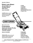
Operator's
Manual
Rotary Lawn Mower
26-inch Wide Cut
Variable Speed
Rear Drive
• Safety
Model 536.885600
• Service And Adjustment
• Repair Parts
• Assembly
• Operation
• Maintenance
CAUTION: Before using this
product, read this manual
and follow all of its Safety
Rules and Operating
Instructions.
/
Manual del usario
Cortac sped
Ancho de corte de 26 pulg.
Velocidad variable
Traccibn trasera
Modelo 536.885600
PRECAUCION:
Antes de usar este
producto, lea este manual y siga
todas las reglas de seguridad e
instrucciones de operaci6n.
•
•
•
•
Seguridad
Ensamblaje
Operacibn
Mantenimiento
• Servicio y ajustes
• Piezas de repuesto
Sears, Roebuck and Co., Hoffman Estates, IL. 60179 U.S.A.
F-010472M
www.sears.com/craftsman
TABLE OF CONTENTS
WARRANTY
....................................
OWNER'S INFORMATION
........................
CUSTOMER RESPONSIBILITIES
.................
PREPARATION ..................................
UNPACKING INSTRUCTIONS
IMPORTANT!
OPERATION
2
HOW TO CHANGE THE OIL .....................
15
4
HOW TO CLEAN THE COOLING SYSTEM ........
15
4
HOW TO CHECK THE MUFFLER
15
6
...................
HOW TO CLEAN THE AIR FILTERS (FLAT TYPE)
6
BEFORE YOU START MOWING ....
....................................
SERVICE AND ADJUSTMENT
8
9
HOW TO ENGAGE THE BLADE
9
.................
HOW TO CHANGE THE HEIGHT OF CUT .........
17
DRIVE SYSTEM ..
17
HOW TO REPLACE THE BELTS .................
18
HOW TO ADJUST THE DRIVE CABLE
19
...........
9
...
11
BEFORE STARTING THE ENGINE ...............
12
HOW TO START THE ENGINE ...................
12
.................................
......................................
20
10
MULCHING TIPS ...............................
MAINTENANCE
16
....................
HOW TO ADJUST THE BLADE
STORAGE
HOW TO OPERATE THE REAR WHEEL DRIVE
. 16
HOW TO CHECK THE SPARK PLUG .............
7
HOW TO USE THE THROTTLE CONTROL ........
................
FOLDING HANDLE STORAGE
..................
20
STORAGE (OVER 30 DAYS) .....................
TROUBLESHOOTING
SLOPE GUIDE
13
20
CHART ....................
21
..................................
22
ENGINE TIPPING ...............................
13
INDEX ..........................................
26
HOW TO REMOVE AND INSTALL THE BLADE ....
14
REPAIR PARTS
27
HOW TO SHARPEN THE BLADE
14
ESPANOL
15
REPAIR PARTS ORDERING INFORMATION ........
HOW TO CHECK THE OIL
................
......................
LIMITED
WARRANTY
ON CRAFTSMAN
.................................
......................................
EQUIPMENT
40
64
PARTS
For two (2) years from the date of purchase, if this Craftsman Equipment is maintained, lubricated and tuned up according to
the instructions in the owner's manual, Sears will repair or replace free of charge any parts found to be defective in material
or workmanship. Warranty service is available free of charge by taking your Craftsman equipment to your nearest Sears Service
Center. In-home warranty service is available but a trip charge will apply. This Warranty applies only while this product is in the
United States.
This Warranty does not cover:
•
•
Expendable items which become worn during normal use, such as blades, spark plugs, air cleaners, belts, and oil filters.
Tire replacement or repair caused by punctures from outside objects, such as nails, thorns, stumps or glass.
•
Repairs necessary because
capability of the equipment,
Repairs necessary because
by improper storage, failure
debris, or failure to maintain
•
•
•
of operator abuse, including but not limited to, damage caused by towing objects beyond the
impacting objects that bend the frame or crankshaft, or over-speeding the engine.
of operator negligence, including but not limited to, electrical and mechanical damage caused
to use the proper grade and amount of engine oil, failure to keep the deck clear of flammable
the equipment according to the instructions contained in the owner's manual.
Engine (fuel system) cleaning or repairs caused by fuel determined to be contaminated or oxidized (stale). In general, fuel
should be used within 30 days of its purchase date.
Equipment used for commercial or rental purposes.
TO LOCATE THE NEAREST SEARS SERVICE CENTER OR TO SCHEDULE SERVICE, SIMPLY CONTACT SEARS AT
1-800-488-1222.
This warranty gives you specific legal rights, and you may also have other rights, which vary, from state to state.
Sears, Roebuck and Co., D/817WA, Hoffman Estates, IL 60179.
F-010472M
2
/
Congratulations
onyourpurchase
ofa Craftsman
Rotary
Lawn
Mower.
Ithasbeendesigned,
engineered
andmanufactured
to
giveyouthebestpossible
dependability
andperformance.
Ifyouexperience
anyproblems
youcannot
easilyremedy,
please
seeyournearest
SearsService
Department.
Wehave
competent,
welltrained
technicians
andtheproper
toolsto
service
orrepairthisunit.
Please
readandkeepthismanual.
Theinstructions
willenable
youtoassemble
andmaintain
yourunitproperly.
Always
observe
the"Safety
Rules".
FEATURES
Rotary
Lawn Mower
Record in the space below the serial number and the date
of purchase of this unit.
The model number and serial number are found on a decal
attached to the unit.
Model Number: 536.885600
Serial Number:
Date of Purchase:
Variable Speed Transmission:
Quickly and easily set the for-
Keep these numbers for future reference.
ward speed.
Large Cutting
Width:
26-inch cutting width.
Mow or Mulch: Side discharge attachment can be easily
installed.
Quick Type Height Adjustment:
MAINTENANCE
A Sears Maintenance Agreement is available on this unit. See the
nearest Sears Store for information.
Single lever adjust all wheels.
NOTE: This unit is equipped with an internal combustion engine
and must not be used on or near any unimproved forest-covered,
brush-covered or grass-covered land unless the engine's
exhaust system is equipped with a spark arrester meeting
applicable local or state laws (if any). If a spark arrester is used, it
must be maintained in effective working order by the operator.
Engine Exhaust, some of its constituents,
and
certain vehicle components
contain or emit
chemicals
known to the State of California to
cause cancer and birth defects
ductive harm.
or other
In the State of California, the above is required by law (Section
4442 of the California Public Resources Code). Other states may
have similar laws. Federal laws apply on federal lands. See a
Sears Service Center for a spark arrester for the muffler.
repro-
Battery posts, terminals
and related accessories contain lead and lead compounds,
chemicals known to the State of California to cause
cancer and birth defects or other reproductive
harm. WASH HANDS AFTER HANDLING.
F-010472M
AGREEMENT
3
OWNER'S
INFORMATION
CUSTOMER
It is the owner's responsibility to follow the instructions
low.
1.
2.
3.
4.
5.
6.
7.
8.
RESPONSIBILITIES
be-
Carefully read and follow the rules for safe operation.
Follow all the assembly instructions.
Inspect the unit.
Make sure that the operator of the unit knows how to correctly
use all standard and accessory equipment.
Operate the unit only with guards, shields, and other safety
items in place and working correctly.
Correctly adjust the unit.
Service the unit only with authorized or approved replacement
parts.
Complete all maintenance on the unit.
SAFE OPERATION
PRACTICES
Environmental
Awareness
•
Do not fill the engine's fuel tank completely full.
•
Drain fuel for off-season
•
Use only unleaded gasoline.
•
Service the air cleaner regularly.
•
Change oil regularly. Use 10W-30 oil in summer.
•
Tune-up the engine regularly.
•
Keep equipment in efficient operating condition.
•
Dispose of used engine oil properly.
storage.
FOR WALK-BEHIND
MOWERS
WARNING: This cutting machine is capable of amputating hands and feet and throwing objects. Failure to observe the
following safety instructions could result in serious injury or death.
This cutting machine is capable of amputating hands and feet
and throwing objects. Failure to observe the following safety instructions could result in serious injury or death.
L
General
Operation
1. Read, understand, and follow all instructions on the machine
and in the manual(s). Be thoroughly familiar with the controls
and the proper use of the mower before starting.
2.
Do not put hands or feet near or under rotating parts. Keep
clear of the discharge opening at all times.
3. Only allow responsible individuals, who are familiar with the
instructions, to operate the mower.
4. Thoroughly inspect the mower and area where the equipment
is to be used. Clear the area of objects such as rocks, toys,
wire, bones, sticks etc., which could be picked up and thrown
by the blade.
5. Be sure the area is clear of other people before mowing. Stop
mower if anyone enters the area.
13. Mow only in daylight or good artificial light.
14. Do not operate the mower while under the influence of alcohol, drugs or other medication which can cause drowsiness or
affect your ability to operate this machine safely.
15. Never operate mower in wet grass. Always be sure of your
footing; keep a firm hold on the handle and walk; never run.
16. Disengage the self-propelled mechanism or drive clutch on
mowers so equipped before starting the engine (motor).
17. If the equipment should start to vibrate abnormally, stop the
engine (motor) and check immediately for the cause. Vibration
is generally a warning of trouble such as a blade that is damaged, a loose blade, or the engine mounting bolts are loose.
18. Always wear safety goggles or safety glasses with side
shields when operating mower to protect your eyes from foreign objects which can be thrown from the unit.
19. Plan your mowing pattern to avoid discharge of material toward roads, sidewalks, bystanders and the like.
6.
Do not operate the mower when barefoot or wearing open
sandals. Always wear substantial foot wear.
20. After striking a foreign object, stop the engine. Remove the
wire from the spark plug. Inspect the blade and mower for
damage. If damaged, repair before starting and operating the
mower.
7.
Do not pull mower backwards unless absolutely necessary.
Look down and behind before and while moving backwards.
21. Keep any washout ports and other mower housing service
openings closed when mowing.
8.
Do not operate the mower without proper guards, plates,
grass catcher or other safety protective devices in place.
9. See manufacturer's instructions for proper operation and
installation of accessories. Only use accessories approved by
the manufacturer.
10. Stop the blade(s) when crossing gravel drives, walks, or
roads.
11. Stop the engine (motor) whenever you leave the equipment,
before cleaning the mower or unclogging the chute.
12. Shut the engine (motor) off and wait until the blade comes to
complete stop before removing grass catcher.
F-010472M
II. Slope
Operation
Slopes are a major factor related to slip and fall accidents which
can result in severe injury. All slopes require extra caution. If you
feel uneasy on a slope, do not mow it.
DO:
Mow across the face of slopes; never up and down. Do not
mow excessively steep slopes (maximum 15 degrees) or
areas where the ground is very rough. See the "Guide" in the
back of this manual to check a slope. Exercise extreme caution when changing direction on slopes.
Remove objects such as rocks, tree limbs, etc.
OWNER'S
INFORMATION
Watch for holes, ruts, or bumps. Tall grass can hide obstacles.
ning. Disconnect the spark plug wire, and keep the wire away
from the plug to prevent accidental starting. Always wear eye
protection when you make adjustments or repairs.
DO NOT:
Do not mow near drop-offs, ditches, or embankments.
operator could lose footing or balance.
Do not mow excessively
The
steep slopes.
Do not mow on wet grass. Reduced footing could cause slipping.
Tragic accidents can occur if the operator is not alert to the presence of children. Children are often attracted to the mower and
the mowing activity. Never assume that children will remain
where you last saw them.
1. Keep children out of the mowing area and under the watchful
care of a responsible adult.
3. Before and while moving backwards, look behind and down
for small children.
5.
Use extra care when approaching blind corners, shrubs, trees,
or other objects that may obscure vision.
Never tamper with safety devices. Check their proper operation regularly.
7.
Stop and inspect the equipment if you strike an object. Repair,
if necessary, before restarting.
8.
Never attempt to make wheel height adjustments while the
engine (motor) is running.
10. Grass catcher components are subject to wear, damage, and
deterioration, which could expose moving parts or allow objects to be thrown. Frequently check components and replace
with manufacturer's recommended parts, when necessary. For
storage, always make sure grass catcher is empty.
11. Mower blades are sharp and can cut. Wrap the blade(s) or
wear gloves, and use extra caution when servicing them.
IV. Service
"1. Use extra care in handling gasoline and other fuels. They are
flammable and vapors are explosive.
12. Do not change the engine governor setting or over-speed
engine.
a. Use only an approved container.
c. Never refuel the machine indoors.
d. Never store the machine or fuel container inside where there
is an open flame, such as a water heater.
*2. Never run an engine indoors or inside a closed area.
14. Use only original equipment or authorized replacement parts.
Never make adjustments or repairs to items such as the
height adjusters or grass catcher with the engine (motor) run-
* Asterisked items do not apply to electric mowers.
precautions.
symbol
indicates:
"Attention!
Look for this This
symbol
to indicate
important
safety
Become Alert! Your Safety Is At Risk."
F-010472M
the
13. Frequently check the blade for wear or damages such as
cracks and nicks. A blade that is bent or damaged must be
immediately replaced with a factory replacement blade. For
safety and good cutting performance, replace the blade every
two years. Frequently check the blade bolt and the engine
mounting bolts. Replace damaged bolts and tighten loose
bolts.
b. Never remove gas cap or add fuel with the engine running. Allow engine to cool before refueling. Do not smoke.
3.
5.
9. Always disconnect electric mowers (live operated) before
cleaning, repairing, or adjusting.
2. Be alert and turn mower off if children enter the area.
Never allow children to operate the mower.
Keep all nuts and bolts, especially blade attachment bolts,
tight and keep equipment in good condition.
6. To reduce fire hazard, keep mower free of grass, leaves, or
other debris build-up. Clean up oil or fuel spillage. Allow mower to cool before storing.
II1. Children
4.
4.
5
PREPARATION
UNPACKING
INSTRUCTIONS
Folded Position
The mower was fully assembled at the factory. When the mower
was put in the carton, the handle was put in a folded position (see
Figure 1). To put the handle in the operating position, follow the
steps below.
Handle
1.
Remove the packing material from the carton.
2.
Remove the side discharge attachment, the oil, and the fuel
stabilizer from the carton. Put the fuel stabilizer in a safe
place until needed for storage.
Side Discharge Attachment
Figure 1
Blade Rotation
Control
3.
Upper Handle
Cut down all four corners of the carton.
Knob
CAUTION: Be careful when you fold or raise the handle. Do
not damage the cables. A cable that is bent will not work
correctly. Before you use the unit, replace a bent or damaged cable.
/
J
Lower Handle
Adjuster Arm
Rope Guide
Knob
4.
Raise the upper handle and the lower handle to the operating position (see Figure 2). Tighten the knobs that secure
the upper handle to the lower handle.
Adjuster Arm
5.
Each adjuster arm has three mounting holes. These
mounting holes will raise the height of the handle approximately four inches. Determine the desired height and mount
the adjuster arms to the lower handle (see Figure 3).
6.
Tighten the knobs that secure the lower handle to the handle brackets.
Figure 2
Adjuster Arm
Lower Handle
Handle Bracket
7.
Knob
To attach the recoil-start
grip to the rope guide, twist the
rope through the rope guide mounted on the right side of the
handle (Figure 2).
F-010472M
Figure 3
6
PREPARATION
HOW TO PREPARE
THE ENGINE
ENGINE DOES NOT CONTAIN OIL OR GASOLINE
See "Before Starting The Engine" in the Operation section for the
type of oil and gasoline to use. Before you use the unit, read the
information on safety, operation, maintenance, and storage.
IMPORTANT: This unit is equipped with an internal
combustion engine and must not be used on or near any
unimproved forest-covered,
brush-covered or
grass-covered land unless the engine's exhaust system is
equipped with a spark arrester meeting applicable local or
state laws (if any). If a spark arrester is used, it must be
maintained in effective working order by the operator.
In the State of California the above is required by law
(Section 4442 of the California Public Resources Code).
Other states may have similar laws. Federal laws apply on
federal lands. See a Sears Service Center for a spark
arrester for the muffler.
In some areas, local law requires the use of a resistor spark
plug to control the ignition signals. See a Sears Service
Center for a resistor spark plug for the engine.
FINAL PREPARATION
IMPORTANT!
Before you mow, check the handle and the controls. Make sure
all fasteners are tight.
C) The engine was shipped without engine oil. Make
_
YOU START MOWING
sure to fill the engine with the correct amount of engine oil,
nance
to theBefore
mower,doing
remove
wire from orthemaintespark
ARNING:
anytheassembly
plug.
F-O10472M
BEFORE
E_I Fill the fuel tank with gasoline.
7
OPERATION
Blade Rotation Control
Drive Lever
\
Blade Rotation
Transmission"
Speed Control
Throttle Control
Recoil-Start
Grip
Oil Fill
Single Lever
Height Adjuster
Gas Fill
Primer Button
Mulch Cover
Attachment
Side Discharge
Attachment
Figure 4
KNOW YOUR
BLADE ROTATION
CONTROL:
For the blade to ro-
tate, the blade rotation control must be in the ENGAGED position
(against the handle). To quickly stop the blade, release the control.
PRODUCT
MULCH COVER
ATTACHMENT:
Useto
mulch the
grass.
SIDE DISCHARGE
ATTACHMENT:
Useto dis-
charge the grass out the side.
BLADE
CONTROL
LEVER:
Usethe
blade control
SINGLE
LEVER HEIGHT
lever to engage the blade.
quickly change the cutting height.
DRIVE LEVER:
THROTTLE
To quickly disengage the drive, release the
drive lever.
Useto
Use the throttle control lever to
increase or decrease the speed of the engine.
RECOIL-START
the recoil-start
CONTROL:
ADJUSTER:
GRIP:
PRIMER
To start the engine, quickly pull
grip.
TRANSMISSION
BUTTON:
When starting a cold engine, use the
primer button the choke the engine.
SPEED
CONTROL:
the forward speed, move the transmission
F-010472M
OIL FILL / DIPSTICK:
Toincrease
GAS FILL:
speed control forward.
8
Useto check
Use to add gasoline.
and add oil.
OPERATION
HOW TO USE THE THROTTLE
CONTROL
Use the throttle control to increase or decrease the speed of the
engine.
1. To increase the engine speed, move the throttle control
forward to the FAST position. For normal operation and when
using a grass bagger, move the throttle control to the FAST
position. Also, for a cooler running engine, operate the engine in the FAST position.
2.
The engine governor is set at the factory for maximum performance. Do not adjust the governor to increase the speed
of the engine.
HOW TO ENGAGE
THE BLADE
Blade Control Lever
1.
When you start the engine, do not engage the blade rotation control.
2.
To rotate the blade, hold the blade rotation
ENGAGE position (against the handle).
3.
With the blade rotation control
blade control lever forward.
4.
To stop the blade, release the blade rotation control. Before you leave the operator's position, make sure the blade
has stopped rotating.
HOW TO CHANGE
control
Throttle Control
5.
in the
1.
Disengage the adjuster
Move the adjuster
THE HEIGHT
_
OF CUT
arm.
arm to another position.
r Arm
Rear Wheel
F-010472M
Before you go across a sidewalk or a road, release the
blade rotation control to stop the blade.
against the handle, push the
To change the height of cut, move the position of the adjuster arm
(see Figure 6).
2.
Figure 5
Figure 6
9
from
the blade,
deflector
opening,
thefeet
mower
ARNING:
Always
keep your
handsand
and
away
housing when the engine runs.
OPERATION
HOW TO OPERATE
THE REAR WHEEL
DRIVE
IMPORTANT: When you operate, always operate with the
throttle control in the FAST position.
NOTE: To stop the engine, move the throttle control lever to the
OFF position.
WARNING:
For safe operation, the drive system
Height Of Cut
is
released.
If the drive
systemwhen
doesthe
notdrive
disengage
must
immediately
disengage
lever
correctly, do not operate the mower until the drive
system is adjusted or repaired by a Sears service
center.
Set the height of cut. See "How To Change The Height Of Cut". In
high or thick grass, cut the grass in the highest position first and
then change to a lower position.
Rear Wheel
Drive System
Engage
Hold Ag;
The mower has a multi-speed transmission with a rear wheel
drive system. To change the speed, follow the steps below.
1.
Start the engine. See "How To Start The Engine".
2.
DO NOT engage the drive lever.
3.
Move the transmission
speed control
sired speed (see Figure 7).
forward to the deDrive Lever
,_
WARNING:
better
select a safe For
speed.
control
of the unit,
always
4.
To go forward, hold the drive lever against the handle in the
ENGAGED position.
5.
When operating, always keep both hands on the handle (see
Figure 8).
6.
To stop forward motion, release the drive lever.
7.
To shift to a different speed, release the drive lever. Move
the transmission
speed control to another speed.
TransmissionSpeed
Control
Figure 7
Check the operation of the drive system as follows.
1.
With the engine not running and the drive lever in the DISENGAGED position, pull the mower backwards. The rear
wheels must freely turn.
2.
With the engine not running and the drive lever in the ENGAGED Position, pull the mower backwards. The rear
wheels must now be engaged and will not turn.
3.
If the drive system does not operate correctly, adjust the
drive cable. See "How To Adjust The Drive Cable" in the
maintenance section.
F-010472M
Figure 8
10
OPERATION
HOW TO INSTALL
THE SIDE DISCHARGE
ATTACHMENT
_
ARNING:
prevent
the spark
engineplug.
from starting, disconnect
theTo
wire
from the
1.
Remove the three wingnuts that secure the mulch cover to
the mower housing (see Figure 9).
2.
Remove the mulch cover.
3.
Mount the side discharge attachment on the mower housing (see Figure 10).
4.
Make sure the side discharge attachment is mounted on all
three bolts and fasten with the wingnuts that were removed
in step 1.
Wingnut
Wingnut
Side Discharge
Attachment
Wingnut
Wingnut
Figure 9
MULCHING
Figure 10
TIPS
When you use a mulcher attachment, the grass is cut into very
small pieces. These small pieces will quickly break down.
Because the nutrients are returned to the soil, the lawn will need
less fertilizer. To correctly mulch the grass, follow the steps
below.
1.
2.
Set the throttle in the FAST position. Operate the mower at a
slower ground speed. If ground speed is too fast, the grass
will not have an even cut.
Keep a sharp edge on the blade. A blade that is not sharp
will cause the ends of the grass to become brown.
F-010472M
11
3.
Make sure the grass is dry. Wet grass is difficult to cut.
4.
Set the height of the mower housing so that only the top third
of the grass is cut. If the grass is too high, set the height of
the mower housing to the maximum height. Then, lower the
mower housing for the second cut. Also, instead of using the
full width of the mower housing, mulch at half the width.
5.
Clean the bottom of the mower housing. Grass and other
debris can keep the mower from working correctly.
6.
If the grass grows fast, mulch more often.
7.
If an area needs improvement,
mulch a second time.
OPERATION
BEFORE
STARTING
THE ENGINE
ADD GASOLINE
WARNING: Always use a safety gasoline container.
Do not smoke when adding gasoline to the fuel
tank. Do not add gasoline when you are inside an
enclosure. Before you add gasoline, stop the engine and let the engine cool for several minutes.
ADD OIL
NOTE: This unit is shipped without oil in the engine. Before
adding oil, be sure that the engine is level.
TO FILL WITH OIL
CAUTION: DO NOT overfill the engine with oil or it will
smoke on startup.
1.
Remove the oil dipstick from the oil fill spout. Make sure that
the rim of the oil fill spout is clean.
2.
You received a 20 oz. container of oil with the unit. Slowly
pour 3/4 (15 oz.) of the oil from the container down the oil fill
spout into the engine.
3.
Wait one minute to allow oil to settle. Insert and tighten the
dipstick, then remove it to check the oil level.
4.
Continue adding small amounts of oil and rechecking the
dipstick until it reads full. DO NOT overfill, or the engine will
smoke on startup.
5.
Fuel Tank
Fill the fuel tank with regular
unleaded gasoline. Do not use
premium unleaded gasoline.
Make sure the gasoline is fresh
and clean. Leaded gasoline will
increase deposits and shorten
the life of the valves.
CAUTION: A mixture of alcohol (ethanol or methanol) and
gasoline (called gasohol), will attract moisture and cause
acid deposits during storage. While the unit is in storage, the
acids in the fuel can damage the fuel system.
To prevent engine problems with the fuel system, empty the fuel
system before storage of 30 days or longer as follows.
1. Drain the fuel tank.
Always make sure to retighten the oil dipstick before starting
the engine.
2.
Start the engine. Let the engine run until the fuel lines and
the carburetor are empty.
3.
After storage, make sure you use fresh fuel. See the storage
instructions for additional information.
4.
Never use engine cleaner or carburetor cleaner in the fuel
tank or permanent damage can occur.
HOW TO START THE ENGINE
NOTE: The mower is equipped with a no-adjust carburetor.
For increased performance, the carburetor has been preset
to run in the FAST position. The FAST position will also
improve lubrication and prolong engine life.
1.
Move the throttle control lever to the FAST position.
NOTE: For the engine to start, the throttle control lever
must be in the FAST position.
2.
Push the primer button (see Figure 11). Every time you
push the primer button, wait two seconds. For the number
of times required to push the primer button, see the decal
located on the engine.
Primer Button
Figure 11
NOTE: Do not use the primer button when starting a
warm engine.
3.
Make sure the drive lever is in the DISENGAGED
(see Figure 12).
Position
4.
Stand behind the mower. Rapidly pull the recoil-start
Slowly return the recoil-start grip.
grip.
,__Drive
Lever
NOTE: If the engine does not start after four or five tries,
see the TROUBLESHOOTING
CHART.
5.
Let a cold engine run for several minutes. Begin work when
the engine is warm.
6.
To stop the engine, move the throttle control lever to the
OFF position.
F-010472M
Recoil-StartGrip
12
Figure 12
MAINTENANCE
MAINTENANCE
PROCEDURE
EACH
USE
CHART
FIRST
2
HOURS
Blade, Inspect and Sharpen
Oil, Check
EVERY
25
HOURS
EVERY
50
HOURS
EVERY
100
HOURS
BEFORE
STORAGE
_/
_j
Oil, Change*
_/
_/
Cooling System, Clean
_/
_j
Muffler, Check
_/
Air Filter, Clean / Change
_j
_j
Spark Plug, Check
_/
_/
Spark Plug, Replace
_j
Dusty conditions every 25 hours.
GENERAL
RECOMMENDATIONS
1.
The owner's responsibility is to maintain this product. This
will extend the life of the product and is also necessary to
maintain warranty coverage.
2.
Check the spark plug, blade brake, lubricate the unit, and
clean or replace the air filter once a year.
3.
Check the fasteners. Make sure all fasteners are tight.
4.
Follow the Maintenance section and the Service And Adjustment section to keep the unit in good operating condition.
WARNING:
_
Before you make an inspection, adjust-
theent,
spark
plug. to
Remove
thedisconnect
wire from the
or repair
the unit,
the spark
wire to
plug to prevent the engine from starting by accident.
NOTE: Torque is measured in foot pounds (metric Nm). This
measurement describes how tight a nut or bolt must be, The
torque is measured with a torque wrench,
ENGINE TIPPING
When you service the engine, inspect the blade, or clean the underside of the mower housing; make sure to always tip the engine with the spark plug up. Transporting or tipping the engine
with the spark plug down will cause:
•
Hard starting.
•
Engine smoking.
•
Spark plug fouling.
•
Oil or gas saturation of the air filter.
DO NOT TIP OR STORE UNIT WITH
SPARK PLUG POINTING DOWN.
Figure 13
F-010472M
13
MAINTENANCE
INSPECT
BLADE
10. Tighten the nut that holds the blade to a torque of 35 foot
pounds (47,5 N-m).
WARNING: Before you inspect or remove the blade,
disconnect the wire to the spark plug. If the blade
hits
an object,
stop has
the engine.
Check When
the unit
damage.
The blade
sharp edges.
youfor
hold the blade, use gloves or cloth material to protect your hands.
Blade Adapter
If you keep the blade sharp and inspect the blade for damage,
the blade will cut better and be more safe to operate. Frequently
check the blade for excessive wear, cracks, or other damage.
Frequently check the nut that holds the blade. Keep the nut tight.
If the blade hits an object, stop the engine. Disconnect the wire to
the spark plug. See if the blade is bent or damaged. Check the
blade adapter for damage. Before you operate the unit, replace
damaged parts with original equipment parts. See a Sears
service center in your area. Every three years, have an
authorized service person inspect the blade or replace the old
blade with an original equipment part.
HOW TO REMOVE
AND INSTALL
Blade
Belleville Washer
(Outside rim must be
against the blade.)
HOW TO SHARPEN
THE BLADE
_'J
[_
J
Nut
I
Figure 15
THE BLADE
1.
Drain the fuel tank.
WARNING:
2.
Lift the side of the mower that has the muffler or spark plug.
3.
As you loosen the nut, use a piece of wood to keep the blade
from rotating.
notblade
correctly
if thecracks
blade can
is damaged.
A
that isbalanced
damagedorwith
break and
cause an accident.
4.
Remove the nut, washers, and blade (Figure 14).
Keep a sharp edge on the blade. A blade that is not sharp will
cause the tips of the grass to become brown.
1. Sharpen the blade two times a year or every 25 hours.
2.
Remove the blade according to the instructions in "How To
Remove And Install The Blade".
3.
Hi-Lift
4.
Edge Up _
Mandrel
5.
Blade Adapter
Blade
Belleville Washer
Nut_
_._
Figure 14
Check the blade and the blade adapter according to the
instructions for "Inspect Blade". Replace a badly worn or
damaged blade with an original equipment blade. See a
Sears service center in your area.
6.
Clean the bottom of the mower housing. Remove all the
grass and debris.
7.
Mount the blade and blade adapter on the mandrel
(Figure 14).
8.
Mount the blade so that the hi-lift edges are up. If the
blade is upside down, the blade will not cut correctly and
can cause an accident.
9.
Fasten the blade with the original washers and nut. Make
sure the outside rim of the Belleville washer is against the
blade (Figure 15).
_
A new blade will cut better than a badly worn blade. Every
three years, have an authorized service person inspect the
blade or replace the old blade with an original equipment
blade.
7.
Assemble the blade according to the instructions "How To
Remove And Install The Blade".
Blade
Screwdriver
File
I
Blade is balanced
I when para e to the ground.
Ground
ARNING:
Always
keep
thecan
nut cause
tight that
holds the
blade.
A loose
nut or
blade
an accident.
F-010472M
Clean the blade with a brush, soap and water. Check the
blade. Look for cracks, nicks, or other damage. Replace a
badly worn or damaged blade with an original equipment
blade. See a Sears service center in your area.
Sharpen the blade with a file (Figure 16). Make sure you
keep the original bevel angle.
Make sure the blade is balanced. Use a screwdriver and
hold the blade parallel to the ground (Figure 16). A blade
that is balanced will stay parallel to the ground. If the blade
is not balanced, the heavy end will rotate toward the ground.
Sharpen the heavy end until the blade is balanced.
6.
Washer
5.
Vibration can be caused if the blade is
14
Figure 16
MAINTENANCE
ENGINE
HOW TO CHECK
THE OIL
Fuel Cap
Dipstick
NOTE: Do not check the level of the oil while the engine
runs.
1.
Make sure the unit is level.
2.
Clean the area around the dipstick (Figure 17). Remove the
dipstick. Wipe the oil from the dipstick.
3.
Insert the dipstick into the oil fill tube. Turn the dipstick
clockwise until it is tight. Remove the dipstick. Check the oil
level on the dipstick. The oil level must reach the FULL
mark on the dipstick.
4.
If necessary, add oil until the oil reaches the FULL mark on
the dipstick. The quantity of oil needed from ADD to FULL is
shown on the dipstick. Do not add too much oil.
HOW TO CHANGE
THE OIL
Required
NOTE: Do not drain the oil from a cold engine. Before you
drain the oil, let the engine run for several minutes. Make
sure you do not get oil on the belts.
1.
2.
c 30
grades
2o 321o
1'o
RANGE
_
ANTICIPATED
1_
_,o
BEFORE
_o
NEXT
_,o
3'0
OIL
lo0
4'0
CHANGE
NOTE: Although multi-viscosity oils (5W30, 10W30, etc.)
improve starting in cold weather, these multi-viscosity oils
will result in increased oil consumption when used above
320 F. Check the engine oil level more frequently to avoid
possible engine damage from running low on oil.
Open the oil drain cap.
NOTE: To make the job
cleaner, use an optional
hose to drain the oil.
,o
2_
TEMPERATURE
Oil DrainValve
Turn oil drain valve counterclockwise and pullto release Oil DrainCap
the oil drain valve. See
Figure 18.
SAE viscosity
<
F?
Loosen the oil fill cap to
serve as an air vent.
\
3.
Engine Shroud
Figure 17
Hose
7.
Remove oil dipstick from oil fill spout. Make sure that rim of
oil fill spout is clean.
4.
After draining the oil, close
the oil drain cap.
8.
Slowly pour 15 oz. of the oil down the oil fill spout into the
engine.
5.
To lock the oil drain valve,
push and turn the oil drain
valve clockwise.
9.
Wait one minute to allow the oil to settle. Insert and tighten
the dipstick, then remove it to check the oil level.
6.
Container
Figure18
Only use a high quality detergent oil rated with API service
classification SG. Select the oil's SAE viscosity grade according to the expected operating temperature using the
temperature chart below:
HOW TO CLEAN THE COOLING
SYSTEM
The engine is air cooled. The air that cools the engine enters
through the air screen on top of the engine. Clean the engine
every 100 hours or every year as follows.
1.
Remove any grass, dirt or debris from the air screen with a
cloth or brush.
10. Continue adding small amounts of oil and rechecking the
dipstick until it reads FULL. DO NOT overfill, or the engine
will smoke on startup.
11. Always be sure to retighten oil dipstick before starting engine.
HOW TO CHECK
THE MUFFLER
Check the muffler every 50 hours. Make sure the muffler is correctly mounted and is not loose. If the muffler is worn or burnt,
replace with a new muffler. A worn muffler is a fire hazard and
can damage the engine.
If you mount a spark arrester to the muffler, also check the spark
Inspect the edge of the engine shroud for grass or debris.
arrester when you check the muffler. If the spark arrester is worn
Remove any grass or debris visible at the bottom edge of the
or damaged, replace it with a new spark arrester. See your nearengine shroud.
est Sears service center for a spark arrester.
F-010472M
15
2.
MAINTENANCE
HOW TO CLEAN THE AIR FILTERS
(FLAT TYPE)
NOTE: Never run the engine with the air filters removed. The air
filters will help protect the engine against wear. For the correct
replacement filter, see the parts list for the engine.
1.
Loosen screw and tilt cover down (Figure 19).
2.
Remove the air filters.
3.
Clean the inside of the base and the cover with a cloth.
4.
If equipped with a pre-cleaner, separate the pre-cleaner from
the cartridge. Wash the pre-cleaner in a detergent and water
solution. Let the pre-cleaner thoroughly air dry.
CAUTION: Do not wash the filters in gasoline
solvents that will burn.
or other
5.
To clean the cartridge, lightlytap the cartridge against a hard
flat surface.
6.
If the cartridge is very dirty, replace the cartridge.
Base
Cover
7.
Assemble the air filters.
8.
If equipped with a pre-cleaner, the lipof the per-cleaner must
touch the base of the cartridge.
9.
Pre-cleaner
/
Screw
Cartridge
Pre-cleaner Lip
Mount the tabs on the cover to the slots in the bottom of the
base.
Figure 19
10. Close the cover and secure with screw.
HOW TO CHECK THE SPARK
PLUG
Feeler Gauge
0.030"
1.
Check the gap of the spark plug with a feeler
(Figure 20). The correct gap is 0.030".
gauge
2.
For easy starting and good performance, replace the spark
plug every two years or after every 100 hours of use.
Spark Plug
F-010472M
16
Figure 20
SERVICE AND ADJUSTMENT
HOW TO ADJUST
_
THE BLADE
DRIVE SYSTEM
ARNING:
preventcorrectly.
an injury, the blade rotation
control
mustTooperate
In normal usage, the blade drive system will not require an
adjustment. However, if the cutting performance decreases or the
quality of cut is poor, make the following changes.
1.
Start the engine. Make sure the throttle control is in the FAST
position.
2.
Release the blade rotation control.
3,
Turn the cable adjuster one turn in the direction shown in
Figure 21.
4,
Engage the blade. See "How To Engage The Blade". Mow
for a short distance and again check the quality of cut. If necessary, turn the cable adjuster one more turn to shorten the
cable.
5,
Repeat the adjustment and check the quality of cut.
6.
If the quality of cut does not improve, replace the mower
drive belt. See "How To Replace The Mower Drive Belt". If
replacing the belt does not correct the problem, take the unit
to a Sears service center.
7,
Release the blade rotation control. Stop the engine. Disconnect the wire from the spark plug.
8,
Check the operation of the blade brake. Rotate the pulley
with your hand. Make sure the brake pad is pressed tightly
against the pulley (Figure 22).
_
g,
Drive Control
\
Cable Adjuster
Figure 21
against the Ifpulley,
take pad
the unit
a Sears
WARNING:
the brake
doestonot
press service
tightly
center.
Move the blade rotation control to the ENGAGE position.
Check the pad for the blade brake. If the pad is excessively
worn or damaged, replace the brake pad assembly. Correct
replacement parts and assistance are available from a Sears
service center.
10. Attach the wire to the spark plug and start the engine. Mow
for a short distance and again check the operation of the
blade drive system.
11. If you replace the mower drive belt, turn the cable adjuster
in the OPPOSITE direction as shown in Figure 21. Turn the
cable adjuster until all the adjustment that was set with the
old belt has been removed.
12. When you move the blade rotation control to the
DISENGAGE position, all movement will stop within three
seconds. If there is movement of the belt or the blade continues to rotate, engage and disengage the blade rotation
control five times to remove any excess rubber from a new
mower drive belt. If you need assistance, take the unit to a
Sears service center.
F-010472M
17
SERVICE AND ADJUSTMENT
HOW TO REPLACE
_
THE BELTS
6.
Put the blade drive belt onto the bottom pulley of the engine stack pulley. Make sure that the flat side of the blade
drive belt is against the idler pulley.
7.
Check the routing of the blade drive belt as shown in the
illustration.
theARNING:
wire from
the spark
plug. a belt, disconnect
Before
you remove
Blade Drive Belt
1.
Remove the front belt cover (see Figure 23).
Motion
2.
Remove the blade drive belt from the engine stack pulley
(see Figure 24).
1.
Remove the rear belt cover (see Figure 23).
2.
3.
Remove the blade drive belt from the mandrel pulley.
Remove the blade drive belt from the engine stack pulley
(see Figure 24).
3.
Remove the secondary drive belt from the transmission.
4.
Remove the primary drive belt from the engine stack
pulley and from the variator.
5.
Remove the secondary drive belt.
NOTE: Replace the blade drive belt with an original
equipment belt, See a Sears service center in your area,
4,
5,
Make sure the the cable adjuster is turned so that all adjustment is removed the the blade drive cable. See "How To Adjust The Blade Drive System".
Drive Belts
NOTE: Replace the motion drive belts with original
equipment belts. See a Sears service center in your
area.
To install a new blade drive belt, put the belt around the
mandrel pulley. Make sure that the "V" side of the belt is
against the mandrel pulley.
6.
To install new motion drive belts, reverse the above steps.
Rear Cover
Secondary
Drive
Belt
Front Cover
Transmission
Variator
Primary
EngineStack
Figure 23
Figure 24
F-010472M
18
SERVICE AND ADJUSTMENT
HOW TO ADJUST
THE DRIVE CABLE
If the drive system does not engage and disengage correctly,
check the handle for correct assembly. Make sure that all parts
are in good condition, not broken or bent, and that all fasteners
are tight.
Worn parts and cable stretch will change the performance of the
drive system. When you mow in high or thick grass or on hills, the
drive system can slip. If the drive system is slipping, adjust as
follows or take the mower to a Sears service center.
1.
If the drive system is slipping, loosen the jam nut (see
Figure 25).
2.
Turn the cable adjuster one turn in the direction shown in
the illustration. Test the drive system and check for slippage.
3.
If the drive system still slips, turn the cable adjuster one
more turn to shorten the cable. Again, test the drive system.
4.
Repeat the adjustment and test until the drive system does
not slip.
5.
Before you begin to mow, make sure the drive system will
correctly disengage and that the mower will stop. If the drive
system will not disengage, take the mower to a Sears service center before you operate the mower.
6.
Cable
Adjuster
Tighten the jam nut.
Figure 25
F-010472M
19
STORAGE
FOLDING
HANDLE
STORAGE
CAUTION: Be careful when you fold or raise the handle. Do
not damage the cables. A cable that is bent will not work correctly. Before you use the unit, replace a bent or damaged
cable.
How To Fold The Handle
1.
2.
Remove the adjuster arms from the lower handle (see
Figure 26).
Adjuster Arm
Lower Handle
Loosen the knobs that secure the lower handle to the
handle brackets.
Handle Bracket
Knob
3.
Rotate the handle forward over the engine (see Figure 27). As
you fold the handle, make sure the cables are not around the
loose fasteners and do not become damaged.
Figure 26
How To Raise The Handle
Folding Handle
Adjuster Arms
1.
Liftthe handle intothe operator's position.
2,
Each adjuster arm has three mounting holes (see
Figure 26). These mounting holes will raise the height of
the handle approximately four inches. Determine the desired
height and mount the adjuster arms to the lower handle.
3.
Tighten the knobs that secure the lower handle to the
handle brackets.
STORAGE
Figure 27
oil will protect the cylinder. Install a new spark plug in the
cylinder.
(over 30 days)
At the end of each year, prepare the unit for storage as follows.
5.
Clean the dirt and debris from the cylinder cooling fins and
the engine housing.
6.
Clean the bottom of the mower housing.
7.
Completely clean the mower to protect the paint.
8.
Put the unit in a building that has good ventilation.
WARNING: Do not remove gasoline while inside a
_
uilding,
a fire,
or while you
fumes
cannear
cause
an explosion
or smoke.
a fire. Gasoline
1.
Drain the fuel tank.
2.
Let the engine run until it is out of gasoline.
3.
Drain the oil from the warm engine. Fill the engine crankcase
with new oil.
4.
Remove the spark plug from the cylinder. Pour one ounce of
oil into the cylinder. Slowly pull the recoil-start grip so that the
F-010472M
NOTE: Fuel stabilizer is an acceptable alternative in minimizing the formation of fuel gum deposits during storage, Add
stabilizer to gasoline in fuel tank or storage container, Always follow the mix ratio found in stabilizer container, Run
engine at least 10 minutes after adding stabilizer to allow the
stabilizer to reach the carburetor, Do not drain the gas tank
and carburetor if using stabilizer,
20
TROUBLESHOOTING
CHART
PROBLEM:
The engine will not start.
1. Follow the steps, "How To Start The Engine" in this book.
3.
Check the blade adapter. REPLACE A BROKEN BLADE
ADAPTER.
2.
Electric-Start Models: Clean the battery terminals. Tighten
the cables.
4.
Check for loose engine bolts.
5.
3.
Drain the fuel tank. Clean the fuel line. Replace the fuel filter.
Check for a damaged belt or damaged pulley. Replace the
damaged parts.
4.
Remove the spark plug. Move the throttle to the OFF position. Try to start the engine several times. Install the spark
plug.
6.
If the vibration continues, take the mower to a Sears Service
Center.
5.
Replace the spark plug.
PROBLEM:
The engine
PROBLEM:
The grass does not discharge
1. Stop the engine. Clean the mower housing.
will not turn over.
1.
Follow the steps, "How To Start The Engine" in this book.
2.
Electric-Start Models: Check the level of the acid in the battery. If needed, add water. Charge the battery.
3.
Electric-Start
4.
Electric-Start Models: Check the wiring harness for damage
or a loose connection. Repair the damaged wire.
Models: Replace the fuse.
PROBLEM:
The engine is difficult
1. Replace the spark plug.
2.
2.
Raise the height of cut.
3.
Replace or sharpen the blade.
4.
Move the shift lever to a slower speed.
5.
Move the throttle control to the FAST position.
PROBLEM:
to start.
The grass
is not mulching
correctly.
correctly.
1.
Clean the bottom of the mower housing.
2.
Check for a badly worn blade. Remove and sharpen the
blade. For safety, replace the blade every two years with a
factory replacement blade.
3.
Move the throttle control lever to the FAST position. Check
the speed of the engine according to the "Engine Instruction
Book".
4.
The grass must be dry. If the grass is wet, it will be difficult to
cut and cause heavy clumps of grass.
5.
The grass must not be too tall. Set the height adjusters so
that only the top third of the grass is cut.
Clean or replace the air filter.
PROBLEM:
The engine
loss of power,
1. Check the oil,
does not run smooth
2.
Clean or replace the air filter.
3.
Clean the air screen.
4.
Replace the spark plug.
5.
Replace the fuel filter.
or has a
PROBLEM:
1.
PROBLEM:
speed,
The engine
does not run smooth
at fast
The grass
is not cut even.
Check the height adjustment at each wheel. The height adjustment must be the same for each wheel.
2.
Make sure the blade is sharp.
3.
Check for a bent or broken blade. A DAMAGED BLADE IS
DANGEROUS AND MUST BE REPLACED.
PROBLEM:
The engine will not idle,
1. Replace the spark plug.
4.
Check for a broken blade adapter. REPLACE A BROKEN
BLADE ADAPTER.
2.
Clean or replace the air filter.
PROBLEM:
3.
Drain the fuel tank. Clean the fuel line.
1.
Check the blade drive belt. Make sure the belt is installed
correctly.
2.
Replace the blade drive belt.
1.
2.
Replace the spark plug.
Clean or replace the air filter.
PROBLEM:
A hot engine
1. Clean the air screen.
2.
causes
a decrease
in power,
Check the oil.
PROBLEM:
Excessive
Remove the blade. Check the blade and balance if necessary. See the blade maintenance instructions.
2.
Check for a bent or broken blade. A DAMAGED BLADE IS
DANGEROUS AND MUST BE REPLACED.
F-010472M
blade will not rotate.
PROBLEM:
The unit will not move forward when the
drive lever is engaged,
1. Check the motion drive belts. Make sure the belts are in-
vibration.
1.
The mower
stalled correctly.
21
2.
Adjust the drive cable. See "How To Adjust The Drive Cable".
3.
Replace the motion drive belts.
"11
&
O
PO
t
_1_
_'_/Operate
I
hO
hO
a walk-behind
mower
acr°s%%' Ce°n'sS,'o°
as'
e
,
/___,d=u___ll_m_m_.=.,
1
(J..
_y
I
_f_._
_'_l_,r,.,_
-F-_-__
Operate a riding mower
_.__
uP or down slopefSs_e;e;.
On a riding mower to determine if a slope is safe to mow: (1) disengage the blade(s), (2) put the unit in reverse, and (3) try to back straight up the
slope. If you can back up the slope, it is generally safe to mow. However, if you do not feel safe, or if you are not completely sure, use this guide
anddo not mow a slope that is greater than 15 degrees. If the riding mower is used with a pull-behind or rear mounted attachment,
do not operate the unit on a slope that is greater than 10 degrees.
A 15 degree slope is a hill that increases in height at approximately 2.5 feet in 10 feet.
A 10 degree slope is a hill that increases in height at approximately 1.7 feet in 10 feet.
slopes. Operate a riding mower up or down slopes, never across the face of slopes. Operate a walk-behind mower across the face
Use extreme care at all times, and avoid sudden turns or maneuvers. Follow other instructions in this manual for safety in mowing on
of slopes, never up or down slopes. Use extra care when operating on or near slopes and obstructions.
................................
6u'r E'R#?o'u,BE's 6PBu%'E
.................................
(This
pageapplicable
intheU.S.A.
andCanada
only.)
Briggs & Stratton Corporation (B&S), the California Air Resources Board (CARB)
and the United States Environmental Protection Agency (U.S. EPA)
Emission Control System Warranty Statement (Owner's Defect Warranty Rights and Obligations)
EMISSION CONTROL WARRANTY COVERAGE IS APPLICABLE TO CERTIFIED ENGINES PURCHASED IN CALIFORNIA IN
1995 AND THEREAFTER, WHICH ARE USED IN CALIFORNIA, AND TO CERTIFIED MODEL YEAR 1997 AND LATER ENGINES
WHICH ARE PURCHASED AND USED ELSEWHERE IN THE UNITED STATES (AND AFTER JANUARY 1, 2001 IN CANADA).
California and United States Emission Control Defects Warranty Statement
The California Air Resources Board (CARB), U.S. EPA and B&S are pleased to explain the Emission Control System Warranty on your
model year 2000 and later small off-roadengine (SORE). In California, new small off-road engines must be designed, builtand equippedto
meat the State's stringentanti-smog standards. Elsewhere in the United States, new non-road, spark-ignitionengines certified for model
year 1997 and later,must meet similarstandardsset forth by1he U.S. EPA. B&S must warrant 1heemissioncontrolsystem on your engine for
the periods of time listed below, provided there has been no abuse, neglect or improper maintenance of your small off-road engine.
Your emission control system includes parts such as the carburetor, air cleaner, ignition system, muffler and catalytic converter. Also
included may be connectors and other emission related assemblies.
Where a warrantable condition exists, B&S will repair your small off-road engine at no cost to you including diagnosis, parts and labor.
Briggs & Stratton Emission Control Defects Warranty Coverage
Small off-road engines are warranted relative to emission control parts defects for a period of two years, subject to provisionsset forth
below. If any covered part on your engine is defective, the part will be repaired or replaced by B&S.
Owner's Warranty Responsibilities
As the small off-road engine owner, you are responsible for the performance of the required maintenance listed in your Operating and
Maintenance Instructions. B&S recommends that you retain all your receipts covering maintenance on your small off-road engine, but
B&S cannot deny warranty solely for the lack of receipts or for your failure to ensure the performance of all scheduled maintenance.
As the small off-road engine owner, you should however be aware that B&S may deny you warranty coverage if your small off-road
engine or a part has failed due to abuse, neglect, improper maintenance or unapproved modifications.
You are responsible for presenting your small off-road engine to an Authorized B&S Service Dealer as soon as a problem exists. The
undisputed warranty repairs should be completed in a reasonable amount of time, not to exceed 30 days.
If you have any questions regarding your warranty rights and responsibilities, you should contact a B&S Service Representative at
1-414-259-5262.
The emission warranty is a defects warranty. Defects are judged on normal engine performance. The warranty is not related to an
in-use emission test.
Briggs & Stratton Emission Control Defects Warranty Provisions
The following are specific provisions relative to your Emission Control Defects Warranty Coverage. It is in addition to the B&S engine
warranty for non-regulated engines found in the Operating and Maintenance Instructions.
1. Warranted Parts
Coverage under this warranty extends only to the parts listed below (the emission control systems parts) to the extent these parts
were present on the engine purchased.
a. Fuel Metering System
•
Cold start enrichment system
•
Carburetor and internal parts
•
Fuel Pump
b. Air Induction System
•
Air cleaner
•
Intake manifold
c. Ignition System
•
Spark plug(s)
•
Magneto ignition system
d. Catalyst System
•
Catalytic converter
•
Exhaust manifold
•
Air injection system or pulse valve
e. Miscellaneous Items Used in Above Systems
•
Vacuum, temperature, position, time sensitive valves, and switches
•
Connectors and assemblies
2. Length of Coverage
B&S warrants to 1heinitialowner and each subsequent purchaser that the Warranted Parts shall be free from defects in materials and
workmanship which caused the failure of the Warranted Parts for a periodof two years from 1hedate the engine is delivered to a retaqil
purchaser.
3. No Charge
Repair or replacement of any Warranted Part will be performed at no charge to the owner, includingdiagnostic labor which leads to
the determination that a Warranted Part is defective, if the diagnostic work is performed at an Authorized B&S Service Dealer. For
emissions warranty service contact your nearest Authorized B&S Service Dealer as listed in the "Yellow Pages" under "Engines,
Gasoline," "Gasoline Engines," "Lawn Mowers," or similar category.
4. Claims and Coverage Exclusions
Warranty claims shall be filed in accordance with the provisions of the B&S Engine Warranty Policy. Warranty coverage shall be
excluded for failures of Warranted Parts which are not original B&S parts or because of abuse, neglect or improper maintenance as
set forth in the B&S Engine Warranty Policy. B&S is not liable to cover failures of Warranted Parts caused by the use of add-on,
non-original, or modified parts.
F-010472M
23
5.
6.
Maintenance
Any Warranted Part which is not scheduled for replacement as required maintenance or which is scheduled only for regular inspection to 1heeffect of"repair or replace as necessary" shall be warranted as to defects for the warranty period. Any Warranted Part which
is scheduled for replacement as required maintenance shall be warranted as to defects only for the period of Ume up to 1hefirst scheduled replacement for that pert. Any replacement part that is equivalent in performance and durability may be used in the performance
of any maintenance or repairs. The owner is responsible for the performance of all required maintenance, as defined in the B&S
Operating and Maintenance Instructions.
Consequential Coverage
Coverage hereunder shall extend to the failure of any engine components caused by the failure of any Warranted Part still under
warranty.
Look For Relevant Emissions Durability Period and Air Inde
Information On Your Engine Emissions Label
Engines that are certified to meet the California Air Resources Board (CARB) Tier 2 Emission Standards must displ
information regarding the Emissions Durability Period and the Air Index. Briggs & Stratton makes this information availal
to the consumer on our emission labels.
The Emissions Durability Period describes the number of hours of actual running time for which the engine is certified
be emissions compliant, assuming proper maintenance in accordance with the Operating & Maintenance Instructions. T
following categories are used:
Moderate:
Engine is certified to be emission compliant for 125 hours of actual engine running time.
Intermediate:
Engine is certified to be emission compliant for 250 hours of actual engine running time.
Extended:
Engine is certified to be emission compliant for 500 hours of actual engine running time.
For example, a typical walk-behind lawn mower is used 20 to 25 hours per year. Therefore, the Emissions Durabil
Period of an engine with an intermediate rating would equate to 10 to 12 years.
The Air Index is a calculated number describing the relative level of emissions for a specific engine family. The lower the
Index, the cleaner the engine. This information is displayed in graphical form on the emissions label.
FAMILYYBSXS.1481HH
This is a generic representation
of the emission label typically
found on a certified engine.
F-010472M
24
274459
GENERAL
ENGINE
INFORMATION
MODEL
This is a single cylinder, overhead valve (OHV), air-cooled engine. It is a low emissions engine.
In the state of California, OHV Model Series 110000 and 120000 engines are certified by the California Air Resources
Board to meet emissions standards for 125 hours. Such certification does not grant the purchaser, owner or operator of
this engine any additional warranties with respect to the performance or operational life of this engine. This engine is
warranted solely according to the product and emissions warranties stated elsewhere in this manual.
MODEL SERIES 110000
Bore ................................
2-11/16 in. (68.26 ram)
Stroke ..............................
1-51/64 in. (46.00 ram)
Displacement ........................
10.20 cu. in. (167.4 cc)
MODEL
SERIES
120000
Bore ................................
2-11/16 in. (68.26 ram)
Stroke ...............................
2-3/64 in. (52.00 ram)
Displacement ........................
11.58 cu. in. (189.7 cc)
Note: For practical operation, the horsepower loading should not exceed 85% of rated horsepower. Engine power will
decrease 3-1/2% for each 1,000 feet (300 meters) above sea level and 1% for each 10° F (5.6 ° C) above 77° F (25 ° C). It
will operate satisfactorily at an angle up to 15 °.
TUNE-UP
SPECIFICATIONS
Armature air gap ..........
0.006 - 0.014 in. (0.25 - 0.36 mm)
Spark plug gap ..........................
0.020 in. (0.51 mm)
Valve dearance with valve springs installed and piston 1/4 in. (6 mm) past top dead center (check when engine is cold). See
Repair Manual PIN 274008.
Intake ....................
0.004 - 0.006 in. (0.10 - 0.15 mm)
Exhaust ...................
0.009 - 0.011 in. (0.23 - 0.28 mm)
• This engine is certified to operate on gasoline. Exhaust Emission Control System: EM (Engine Modifications).
EMISSION
CONTROL
Maintenance, replacement or repair of the emission control devices and systems may be performed by any
nonroad engine repair establishment or individual, However, to obtain no charge repairs under the terms and
provisions of the Briggs & Stratton warranty statement, any service or emission control part repair or replacement must be
performed by a factory authorized dealer.
F-010472M
25
INDEX
A
F
Adjustments,
Blade Rotation Control, 17
Gas Fill, 8
Height Adjuster, 8
Filter, Air, 16
Height Of Cut, 9
Fuel, Type, 12
Location Of Controls, 8
G
Air Screen, 15
Mulch Cover Attachment,
Mulching, 11
Gas Fill, Location, 8
B
Blade
Oil Fill, 8
H
Belt, Mower Drive, Adjust, 17
Primer Button, 8
Height Adjuster, Location, 8
Rear Wheel Drive, 10
Height Of Cut, Operation, 9
Recoil-Start
Inspect, 14
Lubrication,
Blade Rotation Control
Start The Engine, 12
Throttle Control, 8, 9
M
P
Maintenance
Blade, 14
Primer Button, Location, 8
Adjust, 17
Blade Rotation Control, 17
Location, 8
Filter, Air, 16
Recoil-Start
Spark Plug, 16
Controls, Location, 8
Mower Drive Belt, Adjust, 17
Drive Lever, Location, 8
Muffler, 15
Mulch Cover Attachment,
Location, 8
Mulcher, Operation, 11
Engage Blade, Operation, 9
O
Engine
Storage, 20
Change, 15
T
Check, 12, 15
15
Muffler, 15
Oil, 12, 15
Type, 12
Throttle Control
Oil Fill, Location, 8
Operation
Trouble Shooting Chart, 21
Blade Rotation Control, 8
W
Starting, 12
Drive Lever, 8
Throttle Control, 9
Engage Blade, 9
F-010472M
Location, 8
Operation, 9
Blade Control Lever, 8
Spark Arrester, 15
Spark Arrester, 15
Speed Control, Location, 8
Oil
Lubrication,
Slope Guide, 22
Spark Plug, 16
Cooling System, 15
Fuel, 12
Safety Rules,
American National
Standard Institute, 4-5
Side Discharge Attachment,
Location, 8
Spark Arrester, 15
E
Grip, Location, 8
S
Storage, 20
Maintenance Chart, 13
D
R
Rear Wheel Drive, Operation, 10
Muffler, 15
C
8
Speed Control, 8
Engine, 15
Sharpen, 14
Blade Control Lever, Location, 8
Grip, 8
Side Discharge Attachment,
L
Remove And Install, 14
8
26
Warranty, 2
CRAFTSMAN
REPAIR PARTS
HANDLE ASSEMBLY
MODEL 536.885600
3
\
5
/
/
/
10
18
9
/
7
6
12
16
17
13
11
/
8
19
14
/
9
15
/
13
15
Key
No.
Description
Key
No.
Part No.
Description
Part No.
1
Lever, Drive
1101188-848
11
Knob, Handle
1101453
2
Control, Blade Rotation
1101160
12
Handle, Lower
1101217-846
3
Control, Blade
1101374
13
Bolt, Handle Support
lx183
5
Screw
3x144
14
Nut, Flange
15x79
6
Nut
15x116
15
Adjuster, Handle
1101154
7
Control, Speed
1101430
16
Cable and Throttle Control
1101376
8
Guide, Rope
672510
17
Bolt, Hex
9
Bolt, Carriage
710175
18
Lever, Blade Stop
1101212-848
10
Handle, Upper
1101218-846
19
Cable, Ddve
1101377
F-010472M
27
CRAFTSMAN
MODEL 536.885600
REPAIR PARTS
DRIVE ASSEMBLY
3
o/
/
6
2
/
/
i
32
/
/
/
27
\
16
3
4
67
\ 2
26
/
33
\
/
\
\
/
8
10
30
\
)_
19
23
35
29
31
34
/
1437
11
/
39'
40
I
22
/
41
42
23
43 ,"t-d_,
44._._[_L_
47
17
_19
/
37
f"
18 \
56
0
45
\
o
_57
58
59'
33
F-O10472M
/
60
28
'_._-__
61
CRAFTSMAN
Key
No.
MODEL 536.885600
Description
REPAIR PARTS
DRIVE ASSEMBLY
Key
No.
35
Part No.
Part No.
Description
Bolt, Shoulder
9x30
1
Engine *
2
Screw
26x270
36
Idler Arm
1101174 Z
3
Tinnerman, "U"
28x75
37
Nut, Flange
15x84
4
Cover, Front
1101164
38
Pulley, Engine
1101156
5
Cover, Transmission
1101166
39
Screw
lx111
6
Screw
26x300
40
Pulley, Idler
56526
7
Cover, Rear
1101165
41
Nut, Blade Pulley
15x121
8
Base Assembly, Engine
1101187-848
42
Pulley, Blade
1101191
9
Spring, Extension
165x151
43
Washer, Split
18x31
10
Crossbar, Rear
1101207
44
Screw
710163
11
Bearing, Axle Support
1101148
45
Nut
45171
12
Screw
710167
46
Belt, Blade Drive
37x117
13
Retainer Assembly, Axle Bearing
1101189
47
Bolt
25x7
14
Screw
710277
48
Jackshaft
1101193
15
Washer, Thrust
17x186
49
Screw
26x233
16
Screw
26x263
50
Brake Assembly, Blade
1101190
17
Retainer Ring
11x29
51
Link, Blade Brake
1101196
18
Gear, Right Pinion
1101152
52
Spring, Torsion
166x27
19
Washer, Spring
20x3
53
Bracket, Front Cover
1101205-848
20
Bracket Assembly, Right Axle
1101235
54
Screw
26x214
21
Pin, Drive
43629
55
Support Assembly, Idler & Brake
1101230 Z
22
Transmission- Note: There are no
internal serviceable parts for the
transmission.
1101233
56
Housing
1101145-848
57
Spacer, Jackshaft
1101194
23
Belt, Transmission
37x118
58
Bolt, Short Engine Mount
25xl 7
24
Bracket Assembly, Left Axle
1101234
59
Bolt, Long Engine Mount
25x18
25
Lever, Spring Height Adjuster
1101192
60
Mandrel Assembly
1001049
26
Screw, Tap
26x297
61
Adapter, Blade
92466
27
Knob, Height Adjuster
671297
62
Blade
1101220E701
28
Gear, Left Pinion
1101153
63
Washer, Cup
17x166
29
Gear
1101211
64
Washer
17x165
30
Screw, Tap
26x296
65
Nut, Blade Mount
15x100
31
Cover, Dust
1101163
66
Nut
15x68
32
Wheel, Drive
1101147
67
Bracket Assembly, Lifter
1101465-848
33
Knob, Axle
672449
--
Instruction Book
F-010472M
34
Pin, Cotter
30xl
* * These parts are included in Key No. 61.
F-010472M
29
CRAFTSMAN
MODEL 536.885600
REPAIR PARTS
FIXED WHEEL ASSEMBLY
4
5
/
10
1
11
2
33
/
12
8
I
I
/
/
14
4
/
./
13/
/
><
10
/
21
6
9
/
13
16
\
\
/
/
/
33
19
31
\
/
43
25
/
23
24
42
F-O10472M
22
30
20
CRAFTSMAN
Key
No.
MODEL 536.885600
Description
REPAIR PARTS
FIXED WHEEL ASSEMBLY
Key
No.
Part No.
Description
Part No.
1
Screw
710277
21
Bracket Assembly, Lifter
1101465-848
2
Brace, Handle Bracket
1101378-848
22
Crossbar Assembly, Front
1101186-848
4
Support, Handle
1101229-846
23
Clip, Front
1101158
5
Bolt, Shoulder
710200
24
Screw
26x300
6
Link, Lifter
1101380-848
25
Knob, Axle
672449
7
Bracket, Left Handle
1101168-848
31
Wheel and Tire
1101146
8
Plate, Index
1101206-848
32
Nut, Flange
15x79
9
Nut, Flange
15x84
33
Bolt, Hex
lx45
10
Screw
710167
34
Bolt, Carriage
2x95
11
Screw
26x233
35
Retainer, Bolt
28x55
12
Bracket, Blade Drive Cable
1101213-848
36
Screw
26x293
13
Support, Handle Adjuster
1101155
37
Baffle, Rear
1101171-848
14
Bolt, Carriage
2x76
38
Deflector, Rear
1101200
15
Bracket, Right Handle
1101169-848
39
Screw
26x245
16
Nut
45171
41
Knob
1101222
17
Housing, Mower
1101145-884
42
Deflector, Chute
1101161
18
Screw
26x301
43
Cover, Mulch
1101162
19
Panel, Front
1101223
20
Pin, Cotter
30x20
F-O10472M
31
MODEL 536.885600
B&S ENGINE 120602-0129-E1
022
7
122
993
51
238 _
10_
029
1034
619
830
_ REQUIRES SPECIAL TOOLS
TO INSTALL. SEE REPAIR
INSTRUCTION MANUAL.
615_
404
9140
383
1023 J1022,
505
J 1058 OWNER'S
616
307
J 1019 LABEL KIT J
24[_
12
32A
15_ 2o_
F-O10472M
32
MANUAL
J
MODEL 536.885600
REF.
NO.
PART
NO.
1
2
3
692670
399269
,299819
4
696340
5
695276
7 *A695166
8
495786
9 ,272481
10
691125
11
12
13
499675
*692232
691137
15
16
20
691680
692823
,399781
22
691092
24
25
26
F-010472M
222698
690021
499631
DESCRIPTION
Cylinder Assembly
Kit-Bushing/Seal
Seal-Oil
(Magneto Side)
Sump-Engine
Head-Cylinder
Gasket-Cylinder Head
Breather Assembly
Gasket-Breather
Screw
(Breather Assembly)
Tube-Breather
Gasket-Crankcase
Screw
(Cylinder Head)
Plug-Oil Drain
Crankshaft
Seal-Oil
(PTO Side)
Screw
(Engine Sump)
Key-Flywheel
Piston Assembly
(Standard)
-Note694167 Piston Assembl,
(.010" Oversize)
694168 Piston Assembl
(.020" Oversize)
694169 Piston Assembl
(.030" Oversize)
Ring Set
(Standard)
-Note692785 Ring Set
(.010" Oversize)
B&S ENGINE 120602-0129-E1
REF.
NO.
PART
NO.
DESCRIPTION
692786 Ring Set
(.020" Oversize)
692787 Ring Set
(.030" Oversize)
27
691866 Lock-Piston Pin
28
499423 Pin-Piston
29
499424 Rod-Connecting
32
691664 Screw
(Connecting Rod)
32A
695759 Screw
(Connecting Rod)
33
499642 Valve-Exhaust
34
499641 Valve-Intake
35
691304 Spring-Valve
(Intake)
36
691304 Spring-Valve
(Exhaust)
40
692194 Retainer-Valve
43
691994 Slinger-Governor/Oil
45
690977 Tappet-Valve
46
694039 Camshaft
51,#oA692668 Gasket-Intake
122,#oA692799 Spacer-Carburetor
146
690979 Timing-Key
189
694543 Bali-Rocker Arm
227
691467 Lever-Governor Control
238
691300 Cap-Valve
306
691232 Shield-Cylinder
307
690345 Screw
(Cylinder Shield)
337
692051 Sparkplug
383
19374 Wrench-Sparkplug
404
690272 Washer
(Governor Crank)
505
231082 Nut
33
REF.
NO.
PART
NO.
529
562
692937
94852
584
692342
585
,691879
615
616
619
690340
691308
691108
635
684
66538
690345
718
741
830
690959
691830
694544
868 *A692044
883 ,A691893
886
696268
914
691108
993 *A694088
1019
693868
1022 *A691890
1023
499624
1026
692045
1029
691230
1034
691343
1058
274782
DESCRIPTION
(Governor Control Lever
Grommet
Bolt
(Governor Control Lever
Cover-Breather
Passage
Gasket-Breather
Passage
Retainer-Governor
Shal
Crank-Governor
Screw
(Cylinder Head Cover)
Boot-Sparkplug
Screw
(Breather Passage
Cover)
Pin-Locating
Gear-Timimg
Stud
(Rocker Arm)
Seal-Valve
Gasket-Exhaust
Gasket Kit-Cylinder
Head/Plate
Screw
(Rocker Cover)
Gasket-Cylinder Head
Plate
Kit-Label
Gasket-Rocker Cover
Cover-Rocker Arm
Rod-Push
Arm-Rocker
Guide-Push Rod
Owner's Manual
MODEL 536.885600
B&S ENGINE 120602-0129-E1
968
633
122
365
445
137
967
276
95
51
11_!zl
443
_
443A _
276
267
843 _
265
529A
621_
202
122
670
287_
1523J
3001
842 _
613_
883 _
564
524_
F-O10472M
34
613 _
MODEL 536.885600
REF.
NO.
PART
NO.
DESCRIPTION
51,,_.A692668 Gasket-Intake
95
691636 Screw
(Throttle Valve)
97
499682 Shaft-Throttle
104
.691242 Pin-Float Hinge
117
498978 Jet-Main
(Standard)
Note
498975 Jet-Main
(High Altitude)
122...A692799
Spacer-Carburetor
125
694202 Carburetor
127
.694468 Plug-Welch
130
691203 Valve-Throttle
133
398187 Float-Carburetor
134
.398188 Kit-Needle/Seat
137 ..693981
Gasket-Float Bowl
163,_.A692667 Gasket-Air Cleaner
187
691050 Line-Fuel
(Cut to Required Length)
188
691147 Screw
(Control Bracket)
190
690940 Screw
(Fuel Tank)
202
691303 Link-Mechanical
Governor
209
691291 Spring-Governor
F-010472M
B&S ENGINE 120602-0129-E1
REF.
NO.
222
265
267
276
287
300
365
425
443
443A
445
523
524
525
529A
564
601
PART
NO.
DESCRIPTION
693378
690798
691044
Bracket-Control
Clamp-Casing
Screw
(Casing Clamp)
..271716
Washer-Sealing
690940 Screw
(Dipstick Tube)
693982 Muffler
691136 Screw
(Carburetor)
690670 Screw
(Air Cleaner Cover)
691637 Screw
(Air Cleaner Primer
Base)
692523 Screw
(Air Cleaner Primer
Base)
491588 Filter-Air Cleaner
Cartridge
499621 Dipstick
.692296 Seal-Dipstick Tube
495265 Tube-Dipstick
691923 Grommet
693808 Screw
(Control Cover)
95162 Clamp-Hose
35
REF.
NO.
604
613
PART
NO.
692669
691108
DESCRIPTION
Cover-Control
Screw
(Muffler)
613A
691140 Screw
(Muffler)
621
692310 Switch-Stop
633 .°691321
Seal-Choke/Throttle
Shaft
670
692294 Spacer-Fuel Tank
832
695593 Guard-Muffler
836
691147 Screw
(Muffler Guard)
836A
692557 Screw
(Muffler Guard)
842
.691031 SeaI-O Ring
(Dipstick Tube)
843
691884 Sleeve-Lever
847
692047 Assembly-Dipstick/Tube
883 -_A691893 Gasket-Exhaust
966
692673 Base-Air Cleaner Primel
967
493537 Filter-Pre Cleaner
968
692298 Cover-Air Cleaner
972
693377 Tank-Fuel
975
493640 Bowl-Float
976
694395 Primer-Carburetor
1059
692311 Kit-Screw/Washer
MODEL 536.885600
B&S ENGINE 120602-0129-E1
65_
592 ®
58
I
459
6O
689 o
1211
592 @
456 _
597
334 _
I 1036
I
LABEL-EMISSIONS
356_
930
332
37
78
363
F-O10472M
23
36
MODEL 536.885600
REF.
NO.
PART
NO.
23
37
55
58
692693
694086
691421
692259
60
65
281434
690837
78
304
305
691108
499676
690960
F-010472M
DESCRIPTION
Flywheel
Guard-Flywheel
Housing-Rewind Starter
Rope-Starter
(Cut to Required Lengthl
Grip-Starter Rope
Screw
(Rewind Starter)
Guard-Flywheel
Housing-Blower
Screw
(Blower Housing)
B&S ENGINE 120602-0129-E1
REF.
NO.
332
333
334
356
363
455
456
459
592
PART
NO.
DESCRIPTION
690662
Nut
(Flywheel)
802574 Armature-Magneto
691061 Screw
(Magneto Armature)
692390 Wire-Stop
19069 Puller-Flywheel
695161 Cup-Flywheel
692299 Plate-Pawl Friction
281505 Ratchet-Pawl
690800 Nut
(Rewind Starter)
37
REF.
NO.
PART
NO.
597
691696
689
851
930
1005
1036
1210
691855
493880
692675
691346
695109
498144
1211
498144
DESCRIPTION
Screw
(Pawl Friction Plate)
Spring-Friction
TerminaI-Sparkplug
Guard-Rewind
Fan-Flywheel
Label-Emissions
Assembly-Pulley/Spring
(Pulley)
Assembly-Pulley/Spring
(Spring)
MODEL 536.885600
B&S ENGINE 120602-0129-E1
358 ENGINE
9
58,.=
GASKET
SET
163
51
993
7
1_
524_
122
20_
3_
842
1095 VALVE GASKET
7
1022
121 CARBURETOR
SET
104_
883
127(_
276
137
633
122
993
977 CARBURETOR
GASKET
SET
633
122
51
F-O10472M
163
51
868
163_
OVERHAUL
137
163 _
38
276
KIT
MODEL 536.885600
REF.
NO.
PART
NO.
DESCRIPTION
3
-k299819 Seal-Oil
(Magneto Side)
7 -_A695166 Gasket-Cylinder Head
9 -_272481 Gasket-Breather
12 -k692232 Gasket-Crankcase
20 -_399781 Seal-Oil
(PTO Side)
51-k..A692668 Gasket-I ntake
104
.691242 Pin-Float Hinge
121
692703 Kit-Carburetor Overhaul
122-k..A692799 Spacer-Carburetor
F-010472M
B&S ENGINE 120602-0129-E1
REF.
NO.
PART
NO.
127
.694468
134
.398188
137 .°693981
163-_..A692667
276 .°271716
358
694090
524 -X-692296
585 -k691879
633 .°691321
DESCRIPTION
Plug-Welch
Kit-Needle/Seat
Gasket-Float Bowl
Gasket-Air Cleaner
Washer-Sealing
Gasket Set-Engine
Seal-Dipstick Tube
Gasket-Breather
Passage
Seal-Choke/Throttle
Shaft
39
REF.
NO.
842
PART
NO.
-k691031
868 -kA692044
883 -kA691893
977
692704
993 -kA694088
1022 -kA691890
1095
694091
DESCRIPTION
SeaI-O Ring
(Dipstick Tube)
Seal-Valve
Gasket-Exhaust
Gasket Set-Carburetor
Gasket-Cylinder Head
Plate
Gasket-Rocker Cover
Gasket Set-Valve
For repair of major brand appliances in your own home
no matter who made it, no matter who sold it!
1-800-4-MY-HOM
E®
Anytime,
dayor night
(1-800-469,4663)
(U.S.A. and Canada)
www.sears.com
www.sears,ca
For repair of carry-in products like vacuums, lawn equipment,
and electronics, call for the location of your nearest
Sears Parts and Repair Center.
1-800-488-1222
Anytime, day or night (U.S.A, only)
www.sears.com
For the replacement parts, accessories and owner's manuals
that you need to do-it-yourself, call Sears PartsDirectSM!
1-800-366-PART
6 a,m.-
11 p.m. CST, 7 days a week
(U.S.A. only)
(1-800-366-7278)
www,sears.com/partsdirect
To purchase or inquire about a Sears Service Agreement
or Sears Maintenance Agreement:
1-800-827-6655
(U.S.A.)
7 a.m. - 5 p.m. CST, Mon.-
Sat.
1-800-361-6665
9 a.m. -8 p.m. EST, M - F, 4 p.m. Sat,
Para pedir servicio de reparaci6n a
Au Canada pour service en fran(_ais:
domicilio, y para ordenar piezas:
1-888-SU-HOGAR
(Canada)
1-800-LE-FOYER
SM
Mc
(1-800-533-6937)
(1-888-784-6427)
--
www.sears.ca
r
HomeCentral®
® Registered Trademark / TMTrademark/SM Service Mark of Sears, Roebuck and Co.
® Marca Registrada/ TM Marca de Fa_brica/ SM Marca de Servicio de sears, Roebuck and Co.
MC Marque
de commerce
/ MD Marque
d_posee
de Searsl
Roebuck
and Co,
© Sears,
Roebuck
and Co.