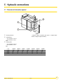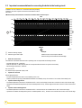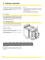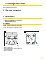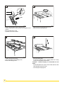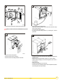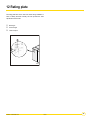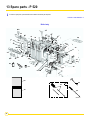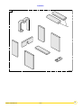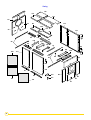
1
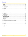
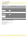
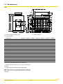
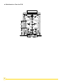
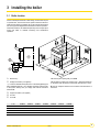
EN Remeha Fuel oil/gas boilers P 520 Installation and Service Manual 300016859-001-A 63115 Declaration of conformity 1 C001878 The appliance complies with the standard model described in declaration of compliance 1. It is manufactured and distributed pursuant to the requirements of European Directives. The original of the declaration of compliance is available from the manufacturer. 2 P 520 02/04/08 - 300016859-001-A Contents 1 General . . . . . . . . . . . . . . . . . . . . . . . . . . . . . . . . . . . . . . . . . . . . . . . . . . . . . . . . . . . . . . . . . . . . . . . . . . . . . . . . .4 2 Description. . . . . . . . . . . . . . . . . . . . . . . . . . . . . . . . . . . . . . . . . . . . . . . . . . . . . . . . . . . . . . . . . . . . . . . . . . . . . .5 2.1 2.2 3 Technical characteristics . . . . . . . . . . . . . . . . . . . . . . . . . . . . . . . . . . . . . . . . . . . . . . . . . . . . . . . . . . . . . . . . . . . . . . . . . . . . . . . . . .6 Main dimensions. . . . . . . . . . . . . . . . . . . . . . . . . . . . . . . . . . . . . . . . . . . . . . . . . . . . . . . . . . . . . . . . . . . . . . . . . . . . . . . . . . . . . . . . .7 Installing the boiler . . . . . . . . . . . . . . . . . . . . . . . . . . . . . . . . . . . . . . . . . . . . . . . . . . . . . . . . . . . . . . . . . . . . . . .9 3.1 3.2 Boiler location . . . . . . . . . . . . . . . . . . . . . . . . . . . . . . . . . . . . . . . . . . . . . . . . . . . . . . . . . . . . . . . . . . . . . . . . . . . . . . . . . . . . . . . . . . .9 Ventilation. . . . . . . . . . . . . . . . . . . . . . . . . . . . . . . . . . . . . . . . . . . . . . . . . . . . . . . . . . . . . . . . . . . . . . . . . . . . . . . . . . . . . . . . . . . . .10 4 Mounting . . . . . . . . . . . . . . . . . . . . . . . . . . . . . . . . . . . . . . . . . . . . . . . . . . . . . . . . . . . . . . . . . . . . . . . . . . . . . .10 5 Hydraulic connections . . . . . . . . . . . . . . . . . . . . . . . . . . . . . . . . . . . . . . . . . . . . . . . . . . . . . . . . . . . . . . . . . . .11 5.1 5.2 5.3 5.4 6 Dimensional information required. . . . . . . . . . . . . . . . . . . . . . . . . . . . . . . . . . . . . . . . . . . . . . . . . . . . . . . . . . . . . . . . . . . . . . . . . . .11 Important recommendations for connecting the boiler to the heating circuit . . . . . . . . . . . . . . . . . . . . . . . . . . . . . . . . . . . . . . . . . .12 Filling the system . . . . . . . . . . . . . . . . . . . . . . . . . . . . . . . . . . . . . . . . . . . . . . . . . . . . . . . . . . . . . . . . . . . . . . . . . . . . . . . . . . . . . . .13 Sludge removal. . . . . . . . . . . . . . . . . . . . . . . . . . . . . . . . . . . . . . . . . . . . . . . . . . . . . . . . . . . . . . . . . . . . . . . . . . . . . . . . . . . . . . . . .13 Chimney connection . . . . . . . . . . . . . . . . . . . . . . . . . . . . . . . . . . . . . . . . . . . . . . . . . . . . . . . . . . . . . . . . . . . . .14 6.1 6.2 Flue size . . . . . . . . . . . . . . . . . . . . . . . . . . . . . . . . . . . . . . . . . . . . . . . . . . . . . . . . . . . . . . . . . . . . . . . . . . . . . . . . . . . . . . . . . . . . . .14 Chimney connection . . . . . . . . . . . . . . . . . . . . . . . . . . . . . . . . . . . . . . . . . . . . . . . . . . . . . . . . . . . . . . . . . . . . . . . . . . . . . . . . . . . . .14 7 Fuel-oil or gas connections . . . . . . . . . . . . . . . . . . . . . . . . . . . . . . . . . . . . . . . . . . . . . . . . . . . . . . . . . . . . . . .15 8 Electrical connections . . . . . . . . . . . . . . . . . . . . . . . . . . . . . . . . . . . . . . . . . . . . . . . . . . . . . . . . . . . . . . . . . . .15 9 Maintenance. . . . . . . . . . . . . . . . . . . . . . . . . . . . . . . . . . . . . . . . . . . . . . . . . . . . . . . . . . . . . . . . . . . . . . . . . . . .15 9.1 9.2 9.3 9.4 Sweeping . . . . . . . . . . . . . . . . . . . . . . . . . . . . . . . . . . . . . . . . . . . . . . . . . . . . . . . . . . . . . . . . . . . . . . . . . . . . . . . . . . . . . . . . . . . . .15 Cleaning the casing material . . . . . . . . . . . . . . . . . . . . . . . . . . . . . . . . . . . . . . . . . . . . . . . . . . . . . . . . . . . . . . . . . . . . . . . . . . . . . .18 Precautions required in the case of long boiler stops (one or more years) . . . . . . . . . . . . . . . . . . . . . . . . . . . . . . . . . . . . . . . . . . .18 Precautions required if the heating is stopped when there is a risk of freezing . . . . . . . . . . . . . . . . . . . . . . . . . . . . . . . . . . . . . . . .18 10 Burner maintenance . . . . . . . . . . . . . . . . . . . . . . . . . . . . . . . . . . . . . . . . . . . . . . . . . . . . . . . . . . . . . . . . . . . . .18 11 System maintenance. . . . . . . . . . . . . . . . . . . . . . . . . . . . . . . . . . . . . . . . . . . . . . . . . . . . . . . . . . . . . . . . . . . . .18 11.1 Water level . . . . . . . . . . . . . . . . . . . . . . . . . . . . . . . . . . . . . . . . . . . . . . . . . . . . . . . . . . . . . . . . . . . . . . . . . . . . . . . . . . . . . . . . . . . .18 11.2 Draining . . . . . . . . . . . . . . . . . . . . . . . . . . . . . . . . . . . . . . . . . . . . . . . . . . . . . . . . . . . . . . . . . . . . . . . . . . . . . . . . . . . . . . . . . . . . . .18 12 Rating plate . . . . . . . . . . . . . . . . . . . . . . . . . . . . . . . . . . . . . . . . . . . . . . . . . . . . . . . . . . . . . . . . . . . . . . . . . . . .19 13 Spare parts - P 520 . . . . . . . . . . . . . . . . . . . . . . . . . . . . . . . . . . . . . . . . . . . . . . . . . . . . . . . . . . . . . . . . . . . . . .20 02/04/08 - 300016859-001-A P 520 3 1 General This product will be marketed in the following European Union member states : NL - BE - ES - GB - HU - SE with a gas burner of the associated category. 4 Warning The boiler shall be assembled and installed by a qualified professional only. For a proper operating of the boiler, follow carefully the instructions. Symbols used Caution danger Risk of injury and damage to equipment. Attention must be paid to the warnings on safety of persons and equipment Specific information Information must be kept in mind to maintain comfort Z Reference Refer to another manual or other pages in this instruction manual P 520 02/04/08 - 300016859-001-A 2 Description The boilers of the P 520 range are pressurised hot water boilers designed for connecting to a flue pipe which require a separate automatic fuel-oil or gas burner. The useful power of P 520 boilers is between 754 and 1450 kW. Models available Boiler with control panel, which may be fitted with an optional Rematic 2945 C3K control unit for heating only or heating and domestic hot water production. 02/04/08 - 300016859-001-A P 520 5 2.1 Technical characteristics Maximum operating pressure : 7.5 bar Boiler thermostat setting : 30 to 90°C Safety thermostat setting : 110 °C Boiler P 520-13 P 520-15 P 520-17 P 520-19 P 520-21 P 520-23 P 520-25 Useful output kW 696 to 754 812 to 870 928 to 986 1044 to 1102 1160 to 1218 1276 to 1334 1392 to 1450 Power input kW 773 to 838 902 to 967 1031 to 1096 1160 to 1224 1289 to 1353 1418 to 1482 1547 to 1611 Number of sections Water content 13 15 17 19 21 23 25 l 617 693 769 845 943 1019 1095 57.6 77.6 30.2 41.4 53.6 64.8 78.4 mbar 25.8 34.7 13.5 18.5 24 29 35 14.4 19.4 7.6 10.4 13.4 16.2 19.6 2.2 2.4 2.6 2.85 3.1 3.3 3.5 ∆ T = 10K Water resistance ∆ T = 15K ∆ T = 20K Pressure in the furnace for nozzle pressure = 0 mbar Flue gas temperature (1) (3) Mass flue gas flow rate (1) (2) Fuel oil Gas Inscribed diameter Combustion chamber Maintenance consumption* K Kg/h mm <190 <190 <190 <190 <190 <190 <190 1070 1220 1370 1520 1670 1820 1970 1120 1280 1440 1590 1750 1910 2070 614 614 614 614 614 614 614 Equivalent diameter mm 694 694 694 694 694 694 694 Depth mm 1372 1594 1816 2038 2300 2522 2744 Volume m3 0.53 0.61 0.70 0.78 0.88 0.96 1.05 ∆ T = 30K % 0.08 0.07 0.07 0.07 0.06 0.06 0.06 kg 3000 3364 3756 4124 4538 4930 5297 Shipping weight *Maintenance consumption: total heat emission when the burner is off as a percentage of the nominal input power when the difference between the mean boiler temperature and the room temperature is 30 K. (1)Nominal operation (top boiler power) (2) CO2 = 13.1 to 13.5% with fuel oil and 9.5% with natural gas. (3)Boiler temperature : 80 °C Ambient temperature : 20 °C 6 P 520 02/04/08 - 300016859-001-A 2.2 Main dimensions P 520 1 A 755 2 P 718 D ØE 50 R K 1080 S 17,5 ** * 616 1566 370 496 C 140 223 100 240 T ØF 3 741 370 U 815 420 791 300 543 ØE 200 M000032 H 1172 B L M G Minimum height for sweeping = 850 Burner centre line Flowrate detector Boiler P 520 P 520-13 P 520-15 P 520-17 P 520-19 P 520-21 P 520-23 P 520-25 A (mm) 1563 1785 2007 2229 2491 2713 2935 B (mm) 1522 1744 1966 2188 2450 2672 2894 C (mm) 1488 1488 1488 1504 1504 1504 1504 D (mm) 256 188 210 257 209 231 253 139.7 139.7 139.7 159 159 159 159 350 400 400 400 * * * G (mm) - 150 370 370 650 980 980 H (mm) 37 -31 -9 13 -35 -13 9 K** (mm) 49 -19 3 25 -23 -1 21 1955 2245 2445 2645 2955 3155 3355 275 324 321 299 324 324 303 355 355 355 355 355 355 355 Ø E (weld) (mm) Ø F (mm) L (mm) M (mm) P (mm) K R (mm) K 175 175 175 175 175 175 175 S (mm) K 1760 1760 1760 1760 1760 1760 1760 T (mm) 1372 1594 1816 2038 2300 2522 2744 U (mm) 2021.5 2243.5 2465.5 2687.5 2949.5 3171.5 3393.5 * Plain plate, requires cutting. Maximum cut-out 500 x 700. ** Dimension representing the end of the 100 mm long chimney connection. G = Length required for clearing the water distributing tube. Nota : with models P 520-21, P 520-23 and P 520-25, a plain plate which must be cut out is supplied without the 100 mm chimney connection. 02/04/08 - 300016859-001-A P 520 7 Main dimensions - Rear view P 520 500 Max 700 max 565 3/4" 610 8 P 520 M000158 02/04/08 - 300016859-001-A 3 Installing the boiler 3.1 Boiler location For the assembly and because of their design, P 520 boilers require no special base. Their closed furnace system means that the floor need not have refractory properties. All you have to ensure is that the floor can support the weight of the boiler when it is fitted for operation. If the boiler location is not determined precisely, leave enough space around the boiler to facilitate monitoring and maintenance operations. Boiler body * If A = 1.2 m (door opening side), A’ = 0.5 m Straight connection (not supplied) * If A = 0.5 m, A’ = 1.2 m (door opening side) : adapt the dimensions on the basis of the dimensions of the burner when the door is open. * 1) In order to facilitate subsequent work on the boiler(replacing the water distributing tube etc.) use a flanged connection from the boiler to the system, making sure you comply with minimum clearance dimension D. B = 1.5 m : adapt the dimensions on the basis of the dimensions of the burner. Angled connection (not supplied) Air inlet Air outlet P 520 P 520-13 P 520-15 P 520-17 P 520-19 P 520-21 P 520-23 P 520-25 L 1955 2245 2445 2645 2955 3155 3355 M 275 324 321 299 324 324 303 C min. 300 436 656 656 936 1266 1266 D min. - 136 356 356 636 966 966 02/04/08 - 300016859-001-A P 520 9 3.2 Ventilation The location of air inlets in relation to the high ventilation openings shall ensure that the air is renewed in the entire volume of the boiler room. It is in any case imperative to conform to the local regulations in force. Caution: In order to avoid damage to the boiler, it is necessary to prevent the contamination of combustion air by chlorine and/or fluoride compounds, which are particularly corrosive. These compounds are present, for example, in aerosol sprays, paints, solvents, cleaning products, washing products, detergents, glues, snow clearing salts, etc. Therefore: • • Do not suck in air evacuated from premises using such products: hairdressing salons, dry cleaners, industrial premises (solvents), premises containing refrigeration systems (risk of refrigerant leakage), etc. Do not stock such products close to the boilers. If the boiler and/or peripheral equipment are corroded by such chloride or fluoride compounds, the contractual guarantee cannot be applied. 4 Mounting For mounting instructions, see installation instructions. 10 P 520 02/04/08 - 300016859-001-A 5 Hydraulic connections 5.1 Dimensional information required M000034 D 3 1080mm C 1 2 H* 2 00 Draining outlet 3/4’’ mm * dimension without connection (see figure on chapter "Boiler location", straight or angled connection). Heating return : - 13 to 17 sections : 139.7 - 5’’ - 18 to 25 sections : 159 - 6’’ weld. Heating outlet : - 13 to 17 sections : 139.7 - 5’’ - 18 to 25 sections : 159 - 6’’ weld. P 520 P 520-13 P 520-15 C (mm) 1488 D (mm) 256 H (mm) 37 02/04/08 - 300016859-001-A P 520-17 P 520-19 P 520-21 P 520-23 P 520-25 1488 1488 188 210 1504 1504 1504 1504 257 209 231 253 -31 -9 13 -35 -13 9 P 520 11 5.2 Important recommendations for connecting the boiler to the heating circuit Installation must be carried out in accordance with the prevailing regulations, the codes of practice and the recommendations in these instructions. `Minimum safety valve flowrate as a function of maximum boiler nominal output : kW 0 100 200 300 400 500 600 700 800 900 1000 1100 1200 1300 1400 1500 1600 1700 1800 6000 14000 13000 12000 5000 11000 10000 4000 9000 7000 3000 kg/h 1 lb/h 8000 6000 5000 2000 4000 3000 1000 2000 1000 0 0 0 1000 2000 3000 4000 6000 5000 MBtu/h 2 M000035 Minimum relieving capacity Example Maximum gross boiler output Maximum boiler nominal output is 800 kW. Minimum safety valve flowrate must be 6000 Kg/h ` Water flow in the boiler : The water flow in the boiler when the burner is operating must correspond with the following formulae: - Nominal water flow Qn = 0.86 Pn/20 - Minimum flow Qmin = 0.86 Pn/45 (this flow also corresponds with the minimum recycle flow in the boiler) - Maximum water flow Qmax = 0.86 Pn/5 Qn = flow in m3/h Pn = Nominal output (full boiler output) in kW. ` Operation in cascade After stopping the burner: - Timeout required before the order to close a butterfly valve: 3 min - Switch a possible shunt pump (located between the boiler and a butterfly valve) off via the end of run contact of the butterfly valve ` Operation with 2-stage burner - The water temperature in the boiler is maintained at 50°C or more ; the first stage must be set to a minimum of 30% of the nominal stage - Operation at modulated low temperature (minimum outlet temperature: 40°C) ; the first stage must be set to a minimum of 50% of the nominal stage ` Operation with modulating burner - The water temperature in the boiler is maintained at 50°C or more: the burner can modulate down to 30% of the nominal stage - Operation at modulated low temperature (minimum outlet temperature: 40°C) ; the burner can modulate down to 50% of the nominal stage 12 P 520 02/04/08 - 300016859-001-A 5.3 Filling the system Filling shall be performed with a low flow rate from a low point in the boiler room in order to ensure that all the air in the boiler is bled from the high point of the system. All the pumps must be stopped before filling (included shunt pump(s)). VERY IMPORTANT : Instructions for starting up the boiler for the first time after the system is fully or partly drained : If all the air is not bled naturally to an expansion vessel which opens out onto the air, the system must include manual bleeder valves, in addition to automatic bleeder valves with the capability to bleed the system by themselves when it is operating; the manual bleeder valves are used to bleed all the high points of the system and to make sure that the filled system is free of air before the burner is turned on. Do not add cold water suddenly into the boiler when it is hot. 5.4 Sludge removal A tapped Ø 2’’ hole with a plug has been provided on the bottom of the front of the boiler.. Fit a 1/4 turn valve (not supplied) on the opening to remove the sludge. Sludge removal leads to the draining of large quantities of water, so remember to refill the system after the operation. M000036 Comments : never replace a boiler in an existing system without carefully rinsing the system first. Install a sludge decanting pot on the return pipe, very close to the boiler. 58 6m m 150mm 1 2’’ tapped sludge removal hole 02/04/08 - 300016859-001-A P 520 13 6 Chimney connection The high-performance features of modern boilers and their use in specific conditions as a result of the advance in burner technology (e.g. first-stage or low modulation range operation) lead to very low flue gas temperatures (<160°C). For this reason : - Use flue gas pipes designed to enable the flow of condensates which may result from such operating modes in order to prevent damage to the chimney. - Install a draining tee at the bottom of the chimney. The use of a draught moderator is recommended as well. 6.1 Flue size Refer to applicable regulations while determining the size of the flue. Please note that P 520 boilers have pressurised and tight furnaces and that the pressure at the nozzle must not exceed 0 mbar, unless special sealing precautions have been taken, for instance in order to connect a static condenser/regenerator. 6.2 Chimney connection The connection shall be removable, and offer minimum load losses, i.e. it must be as short as possible with no sudden change in section. Its diameter shall always be at least equal to that of the boiler outlet, i.e. : ØF Ø 300 mm for 13 sections Ø 400 mm for 14 to 20 sections M000037 Boilers with 21 to 25 sections are supplied with a plain plate. The maximum cut-out dimensions are 500 x 700 mm. Fit a measuring point (Ø 10 mm hole) on the flue, in order to adjust the burner (combustion check). 815mm K 58 P 520 P 520-13 P 520-15 P 520-17 P 520-19 P 520-21 P 520-23 P 520-25 ØF 350 400 400 400 Plain plate Plain plate Plain plate K 49 -19 3 25 -23* -1* 21* 6m m 58 m 6m *Dimension representing the end of the 100 mm long chimney connection mm. Nota : with models P 520-21, P 520-23 and P 520-25, a plain plate which must be cut out is supplied without the 100 mm chimney connection. 14 P 520 02/04/08 - 300016859-001-A 7 Fuel-oil or gas connections Refer to the instructions supplied with the burner. 8 Electrical connections Refer to the connection instructions supplied with the control panel.. 9 Maintenance The operations described below shall only be performed with the boiler and power supply off. 9.1 Sweeping The boiler will only operate efficiently if the exchange surfaces are kept clean. The boiler should be cleaned as soon as required and as the chimney, at least once a year or more, depending upon applicable regulations and specific needs. 1 2 1 2 3 3 4 M000038 - Switch off the boiler electrical power supply. - Remove the upper front panel. - Remove the retaining upper front crosspiece and then the lower left and right-hand front panels. - Remove the lower front panel. 02/04/08 - 300016859-001-A M000039 - Unfasten the wing nuts and remove the 4 sweeping doors. P 520 15 3 4 M000040 M000041 - Remove the baffle plates from the upper flue ways. - Carefully sweep the flue ways with the brush supplied for that purpose. - Brush the baffle plates as well. - If possible, use a vacuum cleaner. - Remove the left and right-hand casing covers. - Remove the top insulating material. 6 5 3 2 1 19 M000043 M000042 - Unfasten the nuts up to the stop. - Push in the handles of the sweeping covers. - Remove the sweeping covers. - Brush the vertical plates. - Put back the sweeping covers, insulating material and casing covers by reversing the procedure above. Comments : chemical sweeping is recommended for such boilers. - Put the baffle plates back in place. Interlock them with each other while fitting them into the flue ways. - Close the upper sweeping doors. 16 P 520 02/04/08 - 300016859-001-A 8 7 19 M000044 - Unscrew the 8 closing nuts and open the furnace door. These 3 screws must not be unfastened in any event. M000045 - Brush out the inside of the furnace. - Clean the soot accumulated in the furnace and lower flue ways with a vacuum cleaner. - Close the lower sweeping doors. - Put back the front casing panels by reversing the removal procedure. 9 1 2 M000046 - Remove the lower rear panels. - Remove the lower rear crosspiece. - Remove the lower insulating material on the rear. 02/04/08 - 300016859-001-A - Unfasten the wing nuts and remove the lower left and right-hand sweeping doors. - Remove any soot deposit with a scraper or a vacuum cleaner. - Open the lower sweeping cover of the flue gas box (2 H 10 nuts + Ø 10 washers). - Remove the soot. - Put back the sweeping cover and doors. - Put back the lower insulating material, the crosspiece and panels by reversing the removal procedure. P 520 17 9.2 Cleaning the casing material Use a soapy solution and a sponge only. Rinse with clean water and dry with chamois leather or a soft cloth. 9.3 Precautions required in the case of long boiler stops (one or more years) (one or several years) The boiler and the chimney must be swept carefully. Close all the doors of the boiler to prevent air from circulating inside the boiler. We advise removing the pipe which connects the boiler to the chimney and to close off the nozzle with a cover. 9.4 Precautions required if the heating is stopped when there is a risk of freezing We recommend the use of a correctly dosed antifreeze agent to prevent to the heating circuit from freezing.If this cannot be done, drain the system completely. 10 Burner maintenance Refer to the instructions supplied with the burner. 11 System maintenance 11.1 Water level Regularly check the level of water in the system and top up if required, taking care that cold water is not added suddenly into the boiler when it is hot. This operation should be required only a few times in each heating season, with very low quantities of water; otherwise, look for the leak and repair it. 11.2 Draining We advise you against draining the system unless it is absolutely necessary. 18 P 520 02/04/08 - 300016859-001-A 12 Rating plate The rating plate fixed on the side of the boiler during installation is used to identify the boiler correctly and also provides the main specifications of the boiler. Boiler type Power ranges Thermic output 3 M000048 02/04/08 - 300016859-001-A P 520 19 13 Spare parts - P 520 To order a spare part, quote the reference number next to the part required. 02/04/08 - 300016859-001-A Boiler body 25 8 37 7 23 21 14 41 39 36 47 42 38 48 6 24 37 30a 38 43 44 10 12 15 21 2a 3 39 27 35 39 34 49 21 32 16 46 26 21 19 46 40 4 17 30 39 31 28 46 29 52 11 5 46 40 13 20 22 9 18 15 45 63 62 61 33 60 M000049 20 P 520 02/04/08 - 300016859-001-A Insulation 70 71 M000050 02/04/08 - 300016859-001-A P 520 21 Casing 116 116 112 92 94 114 86 102 113 93 110 85 104 84 106 100 99 83 101 84 100 97 80 88 98 82 108 105 114 103 88 87 90 96 104 103 80 111 M000051 110 81 89 89 107 95 115 91 22 P 520 02/04/08 - 300016859-001-A Markers Description Markers Code no. Boiler body + Accessories 23 8008-8904 Flange with outlet piece + Gasket 13 to 17 sections Code no. Base frame Description 1 300006596 Complete frame 13 sections 23 8008-8905 Flange with outlet piece + Gasket 19 to 25 sections 1 300006597 Complete frame 15 sections 24 8008-8922 Nozzle + Gasket 1 300006598 Complete frame 17 sections 1 300006599 Complete frame 19 sections 26 8008-8908 Flange with return piece + Gasket 13 to 17 sections 1 300006610 Complete frame 21 sections 26 8008-8909 Flange with return piece + Gasket 19 to 25 sections 1 300006611 Complete frame 23 sections 27 8008-8924 Diaphragm + Gasket 1 300006612 Complete frame 25 sections 28 8228-8905 Complete articulation of furnace plate 29 9757-0424 Plain furnace door 30 9755-0235 Furnace door guard 31 9755-0236 Furnace door insulation Boiler body + Accessories 2 8555-5505 Complete rear section 3 9495-0140 plug no. 290 3/4’’ 4 8259-8948 Normal intermediate section 5 8259-8949 Special intermediate section 6 9495-0110 plug no. 290 1/2’’ 7 8500-0027 1/2’’ sensor tube 8 9758-1286 Spring for pocket 9 8259-8950 Complete front section 10 8006-0212 Painted nipple Ø 148.62 11 9430-5027 Putty for nipple 300 gr 12 9508-6032 Silicone-coated fibreglass seal 13 9428-5095 Silicone filler tube 310 ml 14 8015-8927 Assembly rod Ø 12 - 300 mm 14 8015-8928 Assembly rod Ø 12 - 385 mm 14 8015-8929 Assembly rod Ø 12 - 420 mm 14 8015-8930 Assembly rod Ø 12 - 520 mm 15 9754-0120 Spring for assembly rod 16 8015-8902 Complete indicator with frame 17 8015-7700 Sight glass + Gaskets 18 8015-8913 Assembly rod Ø 14 - 1571 mm 13 sections. 18 8015-8915 Assembly rod Ø 14 - 1796 mm 15 sections. 18 8015-8917 18 18 On demand 9757-0425 Furnace door Ø 165 9757-0426 Furnace door Ø 186 9757-0427 Furnace door Ø 210 9757-0428 Furnace door Ø 295 9757-0429 Furnace door Ø 240 9757-0433 Furnace plate Ø 290 9757-0434 Furnace plate Ø 350 32 8008-8915 Furnace plate hinge 33 8555-8592 Bag of screws for furnace door 34 8555-5528 Flue gas outlet + Thermocord 35 8208-0010 Cast-iron cleaning cover 36 9504-6115 Thermocord gasket Ø 15 37 8555-5508 connection plate Ø 400 + Gasket 37 8555-5506 connection plate Ø 300 + Gasket 37 8555-5507 connection plate Ø 350 + Gasket 37 8555-5509 Plain connection plate + Gasket 38 9508-6041 adhesive gasket 15 x 9 39 8555-5514 Left-hand sweeping door + Thermocord Assembly rod Ø 14 - 2021 mm 17 sections. 40 8555-5541 Right-hand sweeping door + Thermocord Assembly rod Ø 14 - 2246 mm 19 sections. 41 8555-5510 sweeping cover N1 + Thermocord 8015-8919 42 8555-5511 sweeping cover N2 + Thermocord 8015-8921 Assembly rod Ø 14 - 2511 mm 21 sections. 43 8555-5512 sweeping cover N3 + Thermocord 44 8555-5513 sweeping cover N4 + Thermocord 18 8015-8923 Assembly rod Ø 14 - 2736 mm 23 sections. 45 8555-8593 Bag of screws for sweeping door 9508-6032 Silicone-coated fibreglass seal 8015-8925 Assembly rod Ø 14 - 2960 mm 25 sections. 46 18 47 8555-5515 Complete lock 19 8006-8906 Plain square flange + Gasket 48 8259-0010 Upper baffle 20 8006-8907 Square flange with tapped hole + Gasket 49 8008-8910 Distributing tube + Gasket 15 sections 21 9501-4155 Gasket 222 x 170 x 4 49 8008-8911 22 8112-0028 Plug 2’’ Distributing tube + Gasket 17 and 19 sections 02/04/08 - 300016859-001-A P 520 23 Markers Code no. 49 8555-5502 49 Description Markers Code no. Distributing tube + Gasket 21 sections 80 8555-8009 rail 1365 mm 8555-5503 Distributing tube + Gasket 23 sections 80 8555-8010 rail 1475 mm 49 8555-5504 Distributing tube + Gasket 25 sections 80 8555-8011 rail 1565 mm 52 9434-5102 Retouching spray paint - anthracite grey 80 8555-8012 rail 1675 mm Cleaning tools 80 8555-8013 rail 1765 mm 60 9696-8026 Brush for plate 80 8555-8014 rail 1875 mm 61 8013-8704 Metal brush + rod 1800 mm 13 and 15 sections 80 8555-8015 rail 2025 mm 80 8555-8016 rail 2165 mm 62 8015-8716 Metal brush +rod 1300 mm + extensions for 17 to 21 sections 80 8555-8017 rail 2275 mm 62 8015-8723 Metal brush + rod 1800 mm + extensions for 23 to 25 sections 80 8555-8018 rail 2365 mm 81 8555-8021 supplementary rail 1246 mm 63 9750-5103 scraper 1200 mm 82 8555-8035 left-hand cable channel 1260 mm 63 9750-5106 scraper 1500 mm 82 8555-8036 left-hand cable channel 1400 mm 63 9750-5108 scraper 1800 mm 82 8555-8037 left-hand cable channel 1510 mm 82 8555-8038 left-hand cable channel 1600 mm 82 8555-8039 left-hand cable channel 1710 mm Insulating material for body 82 8555-8040 left-hand cable channel 1800 mm Insulation 70 8555-5520 Complete insulating material for body 13 sections 82 8555-8041 left-hand cable channel 1910 mm 8555-8042 left-hand cable channel 2060 mm 8555-5521 Complete insulating material for body 15 sections 82 70 82 8555-8043 left-hand cable channel 2200 mm 70 8555-5522 Complete insulating material for body 17 sections 82 8555-8044 left-hand cable channel 2310 mm 82 8555-8045 left-hand cable channel 2400 mm 70 8555-5523 Complete insulating material for body 19 sections 83 8555-8048 right-hand cable channel 1260 mm 8555-8049 right-hand cable channel 1400 mm 8555-5525 Complete insulating material for body 21 sections 83 70 83 8555-8050 right-hand cable channel 1510 mm 70 8555-5526 Complete insulating material for body 23 sections 83 8555-8051 right-hand cable channel 1600 mm 83 8555-8052 right-hand cable channel 1710 mm 8555-5527 Complete insulating material for body 25 sections 83 8555-8053 right-hand cable channel 1800 mm Insulating material for sweeping covers 83 8555-8054 right-hand cable channel 1910 mm 83 8555-8055 right-hand cable channel 2060 mm 70 71 8555-5533 Complete insulating material for sweeping covers 13 sections 83 8555-8056 right-hand cable channel 2200 mm 8555-8057 right-hand cable channel 2310 mm 8555-5534 Complete insulating material for sweeping covers 15 sections 83 71 83 8555-8058 right-hand cable channel 2400 mm 71 8555-5535 Complete insulating material for sweeping covers 17 sections 84 8555-8080 additional cable channel 1196 mm 85 8555-8066 central upper plate 1131 mm 71 8555-5536 Complete insulating material for sweeping covers 19 sections 85 8555-8067 central upper plate 1271 mm 8555-8068 central upper plate 1381 mm 8555-5538 Complete insulating material for sweeping covers 21 sections 85 71 85 8555-8069 central upper plate 1471 mm 71 8555-5539 Complete insulating material for sweeping covers 23 sections 85 8555-8070 central upper plate 1581 mm 85 8555-8071 central upper plate 1671 mm 8555-5540 Complete insulating material for sweeping covers 25 sections 85 8555-8072 central upper plate 1781 mm 85 8555-8073 central upper plate 1931 mm 85 8555-8074 central upper plate 2071 mm 85 8555-8075 central upper plate 2181 mm 85 8555-8076 central upper plate 2271 mm 71 Casing 80 24 Description 8555-8008 rail 1225 mm P 520 02/04/08 - 300016859-001-A Markers Code no. 86 8555-8079 Description Markers Code no. Description additional central plate 1196 mm 114 8555-8500 rear side panel 400 mm Common parts 114 8555-8501 rear side panel 600 mm 87 8259-8014 Lower front crosspiece 115 8555-8513 Fasteners for rear side panel 88 8555-8515 Fastening bracket for front side pane 116 8555-8505 upper rear plate for sweeping 400 mm 89 8259-8818 Complete lower front side panel 116 8555-8506 upper rear plate for sweeping 600 mm 90 200002992 Complete upper front panel 91 8555-8517 Complete lower front panel Control panel K - RC 1 92 8555-8518 Upper rear panel 93 8259-8021 Lower left-hand rear panel Refer to the Spare Parts list in the panel instructions. 94 8259-8022 Lower right-hand rear panel 95 8259-0518 Panel for furnace door 96 8555-8519 Control panel trim 97 8555-8520 Rear cover for standard control panel 98 8555-8521 Control panel bracket 99 8259-8055 Lower rear crosspiece 100 8555-8522 Upper crosspiece 101 8555-8526 Intermediate upper crosspiece 102 8555-8082 Joining central plate 103 8555-8523 Lower tab of rail 104 8555-8022 Upper bracket 105 8555-0526 Upper front crosspiece 106 9532-0780 Clamp 107 9775-8859 Rapid nut 108 8555-8525 Fasteners for common parts Front side casing - before week 14 / 2008 110 8555-8598 Front side panel - 800 mm 110 8555-8599 Front side panel - 940 mm 110 8555-8616 Front side panel - 1050 mm Front side casing - after week 14 / 2008 110 200007426 Front side panel - 800 mm 110 200007427 Front side panel - 940 mm 110 200007428 Front side panel - 1050 mm 111 8555-8514 Fasteners for front side panel 112 8555-8507 right-hand upper front plate for sweeping 800 mm 112 8555-8508 right-hand upper front plate for sweeping 940 mm 112 8555-8509 right-hand upper front plate for sweeping 1050 mm 112 8555-8510 left-hand upper front plate for sweeping 800 mm 113 8555-8511 left-hand upper front plate for sweeping 940 mm 113 8555-8512 left-hand upper front plate for sweeping 1050 mm Rear side casing 02/04/08 - 300016859-001-A P 520 25 26 P 520 02/04/08 - 300016859-001-A 02/04/08 - 300016859-001-A P 520 27 © Copyright All technical and technological information contained in these technical instructions, as well as any drawings and technical descriptions supplied, remain our property and shall not be multiplied without our prior consent in writing. Subject to alterations. 02/04/08