1
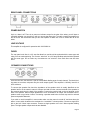
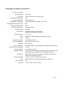
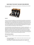
VTA20S
20 Watt Stereo Amplifier
OWNERS MANUAL
This manual provides general, ongoing use and safety information for the VTA20S Stereo Amplifier also
known at the Black Magic 20 Stereo Amplifier.
GENERAL
The Black Magic 20 stereo amplifier is the perfect blend of form and function and the ideal choice for
serious music listeners. It is conservatively rated at 20 watts per channel in stereo mode and 40 watts in
monoblock mode.
This stereo amplifier offers outstanding performance that is difficult to believe, with a high impedance
input, an automatic DC restorer and bias circuit for each channel. Output tube idle current is very low,
which greatly increases tube life. It has ultra-wide bandwidth output transformers with interleaved windings capable of the most nuanced voice as well as huge peak output capacity.
From a listening perspective these amplifiers provide a warm, rich sound with a sumptuous and enveloping sound stage, a great front to back depth of field, and very tight, pin-point imaging within that larger
acoustic. A special current feedback circuit allows the amplifier to “listen to the room” via feedback from
the speakers acting as microphones (using the law of reciprocity). The room-speaker-amplifier interaction provides a sense of believable ambience and acoustic space that is thoroughly realistic and quite
enjoyable. Additionally, the transformer output impedance allows the signal to follow the impedance
curve of the speaker system, allowing more voltage to be delivered to the loudspeaker at very low frequencies – providing an exceptional and satisfying low end response.
SAFE OPERATING CONDITIONS
Before connecting the amplifier up please read the following safe operating conditions.
1. Be cautious when lifting the amplifier. It weighs 19 pounds. Make certain that what it is placed
on can support the weight.
2. The amplifier should be situated so that its location or position does not interfere with its proper
ventilation. The amplifier should never be placed near or over a radiator or heat register. The
amplifier should not be placed in a built-in installation such as a bookcase or cabinet that may
impede the flow of air around the unit. Do not place this amplifier directly on carpeted floors.
3. Do not operate the amplifier plugged into an ordinary extension cord. Heavy duty extension
cords (16 gauge or heavier) have adequate wire size and will not overheat.
4. If you plan on plugging a pair of these amplifier into a switched outlet on a preamplifier be sure
that preamp outlets can handle 100 watts total.
5. Never connect or disconnect inputs or outputs while the amplifier is turned on. Loudspeakers
can be damaged or destroyed by the high power available from the amplifier.
6. The output tubes do get hot when the amplifier power switch is on. Do not touch the output
tubes when the unit is on. If you need to change an output tube, wait 10 minutes after powering
the unit down before you touch the tubes.
7. Turn the amplifier off when not in use to save energy and extend the life of the tubes.
8. Additional safety information is located at the back of this manual.
Page 1
CIRCUIT DESCRIPTION
The input stage of these amplifiers consists of a 12AX7 current sourced, long-tailed balanced pair direct
coupled to the complimentary pair of EL84M tubes. An internal DC restorer ensures that the bias voltage remains correct over the entire audio signal cycle.
Each set of output tubes are arranged in a push pull configuration. The EL84M screen grids are operated at approximately 340 volts, the output tube plate voltage is about 408 volts. The power supply consists of a large power transformer with energy storage that is far greater than necessary. Multiple decoupling filter sections are used with load regulation obtained through zener diode circuit providing constant current loading.
Turn-on in-rush current limiting is provided by a thermistor, bias voltages are automatically set by internal circuits, volume by a stereo volume control on top. A tube cathode fuse protects the output stage in
the event of a catastrophic vacuum tube failure. Finally, a rear mounted power line fuse provides overall
protection for the amplifier.
VACUUM TUBES
The EL84M output tubes do not need to be matched. That's because the DC restorer circuit eliminates
that need. Please note, we have selected the “M” version of the EL84 because it has a higher plate voltage rating than the “non-M” tubes made by many manufacturers. This is how we achieve a full 20 watts
per channel output power by using just one pair each of EL84M tubes. We do not guarantee that replacing these tubes with non-M EL84s will work. Red plating may occur (meaning the tubes will glow red hot)
Looking at the amplifier from the front, the two smaller 12AX7 tubes go right behind the “roll bar”, the
EL84M tubes are installed in the four sockets behind them.
VOLUME CONTROL
Under normal circumstances, this control should be left in the maximum (fully clockwise) position. If you
have a noisy preamp, turning it halfway down and centering it at the 12:00 o'clock position will reduce
the preamp noise by half, or 6 dB. It should always be turned all the way down when connecting or disconnecting any input or output in your system. Connect RCA patch cords from your preamp to the RCA
audio input jacks on the back of this unit.
Note: You may also directly connect a piece of “line level” source equipment to this amplifier with no
preamp and use the volume pot on the amp to adjust the volume. Phonographs cannot be directly to this
amplifier without the use of a phono-prestage preamplifier.
Page 2
REAR PANEL CONNECTIONS
POWER SWITCH
Up is on, down is off. There is no power-on indicator except for the glow of the tubes; you will have to
remember whether you turned it on until you can see the tubes glow. It is safe to switch the amplifier on
and off at will. We recommend that you turn the amplifier off when not in use to extend the life of the
tubes.
LINE VOLTAGE
This amplifier is configured for operation with 120V 50/60 Hz.
FUSES
The rear panel main fuse is a 2.5 amp fast blow fuse, and should be replaced with the same type and
rating if it ever needs replacing. The vacuum “tube fuse” is a 0.25 amp fast blow and should be replaced
with the same type. Do not under any circumstances use "slow-blo" fuses. Both fuses are fast blow
fuses.
SPEAKER CONNECTIONS
From the rear view, the there are 2 pair of red and black binding posts for each channel. The black binding posts are common; red posts carry the audio output signals. This amplifier is “officially” rated for 4
ohms minimum.
To connect the speaker first check the impedance of the speaker which is usually identified on the
speaker itself or in the owner's manual. Connect one lead from the common terminal of the speaker to
the common terminal on the back of the amplifier. Connect the positive lead on the red terminal on the
back of the speaker. When multiple speakers are to be connected to an output, the combined load impedance must not go below 4 ohms. Connecting a speaker rated below 4 ohms may result in reduced
power and possible distortion.
If you wish to use this amplifier in mono mode make sure the power is turned off, and then throw the
stereo / mono switch located on the read panel to “monoblock” or down position. Connect a single RCA
jack to the Left / Mono Input connector. Connect a single speaker to the Left / Mono speaker binding
posts. The right speaker output terminals are disabled.
Page 3
COOLING
Convection cooling - Cool air is drawn from under the chassis by the heat from the tubes acting as an air
pump, and exhausting the warm air out the chassis through the side vents. Do not place the amplifier on
a carpet or in a closed cabinet. You must allow the feet to do their job by keeping the bottom raised, allowing unimpeded airflow.
NEW AMPLIFIER SMELL
We burn-in these amplifier in for 72 hours using a 1 KHZ sine wave driving 4 ohm loads. But, like a
brand new car, this amplifier possesses a "new amplifier smell". When powered up for the first time, the
fresh paint and recent skin oils on the tubes will create a new hot amp smell. It will dissipate with use,
usually requiring about six weeks of normal operation
Page 4
Black Magic 20 Amplifier Specifications
Number of Line Inputs
Input Impedance
Input Stage
Automatic DC Restoration
Nominal Voltage Gain
Output Stage Configuration
1
100K Ohms
12AX7 current sourced low noise valve
Yes
26dB (into 8 ohms)
1 Complementary set of EL84M’s per channel
Regulated Screen Supply Voltage
340V
Output Tube Plate Voltage
408V
Output Tube Idle Power
Bias Adjustment
Rated Power
Output Impedance
Noise
Hum
Less than 9W each
Automatic
20 watts per channel in stereo mode
40 watts in single channel mono mode
4 to 16 ohms
Better than 100dB A weighted referenced into 20 watts
-100dB
Frequency Response
8 Hz to 40kHz (-3dB)
Full Power Bandwidth
26 Hz to 43 kHz without filters
Distortion
Output Transformer
Generator Source Impedance
Speaker Outputs
Construction Method
Components
Dimensions/Weight
Color
Country of origin
Warranty
Less than 0.5%
Interleaved windings, super wideband low leakage inductance design
1.5 ohms
4-16 ohms each channel
Point-to-point hand wired axial and radial leaded components with star
grounds and no circuit board traces or de-plugable connectors
High reliability wire wound and metal film resistors, metal polyester
capacitors in the audio signal paths
13” deep x 9” wide x 7” tall, 19 lbs per chassis
Black with Silver Fleck and brushed silver trim compliments
USA
7 years on amps (1 year on tubes)
Page 5
IMPORTANT SAFETY INFORMATION
Read Information — All the safety and operating information should be read before the amplifier is
plugged in.
Follow Information — All operating and use information should be followed.
Retain Information — Retain the safety and operating information for future reference.
Heed Warnings — All warnings on the amplifier & in the operating instructions should be heeded.
Ventilation — The amplifier should be situated so that its location or position does not interfere with its
proper ventilation. The amplifier should never be placed near or over a radiator or heat register. The amplifier should not be placed in a built-in installation such as a bookcase or cabinet that may impede the
flow of air through the ventilation openings. Do not place this amplifier directly on carpeted floors.
Non-Use Periods — Amplifiers that are left unattended should be turned off via the rear panel switch to
extend the life of the tubes and conserve energy.
Grounding or Polarization — Do not defeat the safety purpose of the polarized or grounding-type plug.
A polarized plug has two blades with one blade wider than the other blade. A grounding type plug has
two blades and a third grounding prong. The polarized wide blade and the third prong are provided for
your safety. If the provided plug does not fit your outlet, consult an electrician for replacement of the obsolete outlet.
Power Cord Protection — Protect the power cord from being walked on or pinched particularly at
plugs, convenience receptacles and the point where they exit from the amplifier.
Water— Do not use the amplifier near water.
Cleaning — Unplug the amplifier from the AC outlet before cleaning. Use only a dry cloth to clean.
Object and Liquid Entry — Never insert objects of any kind through the openings of these amplifiers,
as they may touch dangerous voltage points or short-out parts that could result in a fire or electric shock.
Care should be taken so that objects do not fall and liquids are not spilled into the amplifier through
openings in the enclosure.
Servicing — Do not attempt to service these amplifiers yourself, as opening or removing the bottom
cover WILL expose you to dangerous high voltages. Refer all servicing to Bob Carver LLC.
Damage Requiring Service — These Amplifiers should be serviced by Bob Carver LLC when:
A power supply connection or a plug has been damaged or
If liquid has been spilled into the amplifier or objects have fallen into the amplifier or
The amplifier has been exposed to water or moisture or
The amplifier does not appear to operate normally or exhibits a marked change in performance or
The amplifier has been dropped or the enclosure damaged.
Replacement Parts — When replacement parts are required, be sure the service technician has used
replacement parts specified by the manufacturer or that have the same characteristics as the original
part. Unauthorized substitutions may result in fire, electric shock, or other hazards.
Safety Check — Upon completion of any service or repairs to this audio product, ask the service technician to perform safety checks to determine that the audio product is in proper operating condition.
Lightning Storms — Unplug this amplifier during lightning storms or when unused for long periods
Page 6
CAUTION: - Changes or modifications not expressly approved by BOB CARVER LLC will void
the manufacturer’s warranty.
Page 7
WARRANTIES:
Bob Carver LLC warrants that all equipment manufactured by us to be free from defects
in materials and workmanship for seven (7) years (vacuum tubes – one (1) year).
This warranty shall not apply:
(a) to equipment not manufactured by Bob Carver LLC
(b) to equipment which has been repaired or altered by someone other than Bob
Carver LLC
(c) to equipment which shall have been subjected to negligence, accident, misuse,
abuse, or damage by circumstances beyond Bob Carver LLC’s control, or due to
improper operation, maintenance or storage, or to other than normal use or service.
The foregoing warranties do not cover reimbursement for labor, transportation, removal,
installation, replacement cartons or other expenses which may be incurred by the
dealer in connection with repair or replacement.
If you have any questions concerning the operation or maintenance of this equipment, please contact:
Customer Service
Bob Carver LLC
204 Industry Parkway, Suite F
Nicholasville, KY 40356
Phone: (859) 258-9794
Fax: (859) 258-2150
[email protected]
Page 8