1
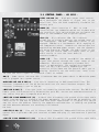
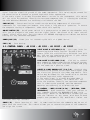
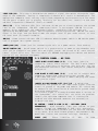
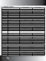
AS 101S - AS 121S - AS 151S
AS 122S - AS 152S - AS 211S
Owner’s Manual
v 09.jun.2010
Congratulations on your purchase of a Markaudio product!
Markaudio is a division of Parsek srl dedicated to pro audio sound reinforcement solutions.
Building on the top-level reputation built up over many years by our industry-leading
bass amplification brand Markbass, Markaudio boasts the same high level of innovation and
engineering.
The result is groundbreaking sound quality, impressive power, and shockingly light
weight.
Markaudio products have been developed by a team of specialists who wrote a chapter in
professional audio history. We are proud to manufacture our products in our
factory in San Giovanni Teatino, Italy, where we’re able to monitor the entire process with
obsessive attention to detail, without compromising on any material choices or
system components. We are constantly striving to improve our engineering, manufacturing
and quality control.
The Markaudio line of PA products is growing in 2010, and some of the new speakers
support the optional Markaudio Tuner System, which allows you to use your computer to tune
your cabinets to perfection. Anyone who has any experience with live sound reinforcement
knows that any PA will sound very different from venue to venue. It’s essential to tune
the PA to the room—to prevent boominess in a large room, for example, or harshness in a
room with highly reflective walls or ceilings. With this innovative PC / MAC software, you
can easily tune your Markaudio system to sound great in any type of venue! Usually slight
tweaks of 1 or 2 dB at crucial frequencies are all you will need to optimize your sound
anywhere.
We invite you to listen and hear the FUTURE, now. I’m quite sure you’ll agree… it sounds
astounding!
And above all, enjoy the Music!
Marco De Virgiliis
General Manager
www.myspace.com/marcodevirgiliis
02
WELCOME TO THE WORLD OF MARKAUDIO
1. AS101S, AS121S, AS151S, AS122SF, AS152SF, AS211S - INTRODUCTION
The AS 101S is an active subwoofer with a single 10” woofer and 500 watts of power. It’s
the smallest subwoofer in the Markaudio product line, with a very compact design and
exceptional bass frequency reproduction.
The AS 121S is a single 12” active subwoofer.
New for 2010, the updated version of the Markaudio AS 121S subwoofer has increased power
from 800W to 1200W, and adds computer connectivity for tuning the cabinet to perfection
with the optional Markaudio Tuner System.
The AS 151S is an active subwoofer with a single 15” woofer.
New for 2010, the updated version of the Markaudio AS 151S subwoofer has increased power
from 800W to 1200W, and adds computer connectivity for tuning the cabinet to perfection
with the Markaudio Tuner System.
The AS 122SF is an active subwoofer with two 12” woofers, and 1200 watts RMS of power.
Combined with the AS 121F, it makes for a lightweight and powerful system,
providing incredible efficiency to any live sound reinforcement application. New Markaudio
AS F cabinets feature ultra-grade felt covering.
The AS 152SF is an active sub-woofer with two 15” woofers, and 1200 watts RMS of power.
Combined with the AS 121F or AS 102, it makes for a lightweight and powerful
system, providing incredible efficiency to any live sound reinforcement application.
The AS 211S is a single 21” active subwoofer that boasts 2000 watts RMS of power.
The AS121S (updated), AS151S (updated), AS122SF, AS152SF, AS211S Markaudio subwoofers
feature computer connectivity for tuning your cabinets to perfection with the optional
Markaudio Tuner System.
03
2. IMPORTANT SAFETY INSTRUCTIONS
1) 2) 3) 4) 5) 6) 7) 8) 9) 10) 11) 12) 13) 14)
15)
16)
Read these instructions;
Keep these instructions;
Heed all warnings;
Follow all instructions;
Do not use this apparatus near water;
Clean only with a dry cloth;
Do not block any ventilation openings. Install in accordance with the
manufacturer’s instructions;
Do not install near any heat sources such as radiators, heat registers, stoves, or other apparatuses (including amplifiers) that produce heat;
Do not defeat the safety purpose of the polarized or ground-type plug. A
polarized plug has two blades with one wider than the other. A grounding type plug has two blades and a third grounding prong. The wide blade or the third prong are provided for your safety. If the provided plug does not fit into your outlet, consult an electrician for replacement of the obsolete outlet;
Protect the power cord from being walked on or pinched, particularly at plugs, convenience receptacles, and the point where they exit from the apparatus;
Only use attachments/accessories specified by the manufacturer;
Unplug this apparatus during lightning storms or when unused for long periods of time;
Refer all servicing to qualified service personnel. Servicing is required when the apparatus has been damaged in any way, such as when the power-supply cord or plug is damaged, liquid has been spilled or objects have fallen into the
apparatus, or when the apparatus has been exposed to rain or moisture, does not operate normally, or has been dropped;
“Warning: to reduce the risk of fire or electric shock, do not expose this
apparatus to rain or moisture; and objects filled with liquids, such as vases, should not be placed on this apparatus”;
The socket outlet shall be installed near the equipment and shall be easily
accessible;
The power cord must be unplugged prior to servicing.
MORE INFORMATION
For warranty and service information, please contact your local Markaudio distributor
(contact information available at www.markaudio.it).
For more technical information, please visit us at www.markaudio.it and fill out the form
on the Contact Us page.
We hope you enjoy your active PA cabinet and use it to make great music!
“The Lightning Flash with arrowhead symbol within an equilateral triangle, is intended to
alert the user to the presence of uninsulated “dangerous voltage” within the product
enclosure that may be of sufficient magnitude to constitute a risk of shock to persons.”
“The exclamation point within an equilateral triangle is intended to alert the user to
the presence of important operating and maintenance (servicing) instructions in the
literature accompanying the product.”
“The
Lightning
Flash
with
arrowhead
symbol
within
an
equilateral triangle, is intended to alert the user to the presence of
uninsulated “dangerous voltage” within the product enclosure that may
be of sufficient magnitude to constitute a risk of shock to persons.”
04
“The exclamation point within an equilateral triangle is
intended to alert the user to the presence of important
operating and maintenance (servicing) instructions in the
literature accompanying the product.”
2. PRÉCAUTIONS D’EMPLOI
1) 2) 3) 4) 5) 6) 7) 8) 9) 10) 11) 12) 13) 14)
15)
16)
Lire ces instructions;
Conserver ces instructions;
Suivre tous les conseils d’utilisations;
Suivre toutes les instructions;
Ne pas utiliser cet appareil au bord de l’eau;
Nettoyer uniquement avec un chiffon humide;
Ne pas bloquer le système de ventilation. Installer conformément aux instructions du fabricant;
Ne pas installer l’appareil près d’une source de chaleur tel qu’un radiateur, un fourneau, ou bien un autre appareil qui produit de la chaleur;
Ne pas modifier le système de sécurité de la fiche polarisée ou de de la fiche pour les prises de terre. Une fiche polarisée a deux broches, l’une étant plus distante de l’autre. Une fiche pour prise de terre a deux broches et une pointe pour la masse. La broche plus distante et la pointe pour la masse ont été
installées pour votre sécurité. Si la fiche fournie de rentre pas dans votre
prise de courant consulter un électricien pour la substitution;
Protéger le cordon d’alimentation afin qu’il ne soit pas piétiné ou écrasé tout particulièrement au niveau des fiches, des prises de courant femelles, et des parties qui sortent de l’appareil;
Utiliser uniquement les accessoires recommendés par le fabricant;
Ne pas branché l’appareil en cas d’orage accompagné d’éclairs. Le débrancher en cas de non utilisation prolongée;
S’adresser à un service assistance agréé si l’appareil a subi des dommages, si le cordon d’alimentation ou la fiche a été endommagé, si un liquide a été renversé sur l’appareil ou bien si un object est tombé dans l’appareil, si ce dernier a été exposé à la pluie ou à l’humidité, s’il ne fonctionne pas correctement
ou s’il est tombé;
“Avertissant: pour réduire le risque du feu ou de décharge électrique, n’exposez pas cet appareil à la pluie ou l’humidité et les objets remplis de liquides; tels que des vases, ne devraient pas être placés sur cet appareil”;
La prise de courant doit être installée près de l’appareil et doit être facile
ment accessible;
La fiche principale doit être débranchée avant toute opération d’entretien.
05
3.1 CONTROL PANEL - AS 101S LEVEL CH1/CH2 (1) - High-pass output level control,
which determines the amount of signal sent to the
satellites. Turn the knob completely clockwise for
unitary gain.
PHASE (2) - Phase inversion 0°- 180°. In some
installations, the subwoofer may be out of phase with
the satellites. This switch allows you to reverse the
phase of the subwoofer and align the system.
CLIP (3) - Clip indicator LED. This indicator
allows you to visually monitor the volume level of
the loudspeaker. LED OFF: compressor/limiter is not
engaged. LED ON for a few moments: brief engaging of
the compressor/limiter, inaudible to the ears—you are
approaching maximum power output, and the speakers
are being protected. LED ON: the audio signal is too
high, and you should lower the output level of your
audio source, or turn the level knob (5)
counterclockwise.
LEVEL (4) - This control determines the amount of
signal that passes through the input stage of the
subwoofer. Turning it completely clockwise will
result in maximum gain. The appropriate subwoofer
level can vary significantly depending on the
acoustics of the venue and the genre of music you’re
playing. Carefully set the satellites’ level first
and then add bass frequencies (subwoofer level) as needed.
ON (5) - Power status indicator LED. Illuminates when the power switch is ON and the power
cord is plugged into a power source.
HIGH-PASS OUT CH1 & CH2 (6) - Line out for connecting to OAS system satellites. The
crossover frequencies for the AS Series satellites are sent from these outputs. The
crossover frequency is set at 120 Hz.
INPUT CH1 & CH2 (7) - Line input jacks for connecting stereo audio sources. The XLR 3-pole
female jacks are electronically balanced (hot pole #2). You can use unbalanced sources if
your cables have pole 3 jumpered with pole 1.
INPUT CH1 & CH2 GROUND LIFT (8) - A switch that disconnects the ground of the input audio
signal from the electric ground of the power amp module. This switch may be needed for the
cancellation of hum due to ground loops with other apparatuses. If flipping this switch
does not solve the problem, identify the apparatus upstream that is creating the problem
and take whatever measures are necessary to eliminate
the hum.
LINK CH1 & CH2 (9) - Line out to connect more subwoofers downstream from the principal
system. This 3-pole male XLR jack receives a female XLR plug (7) and sends out a passive
signal.
LINK CH1 & CH2 GROUND LIFT (10) - A switch that disconnects the ground of the input audio
06
signal from the electrical ground of the power amp module. This switch may be needed for
the cancellation of hum due to ground loops with other apparatuses.
If the audio signal is already disturbed when it arrives to the loudspeaker, this switch
will not solve the problem. Identify the upstream component that is creating the problem,
and take whatever measures are necessary to eliminate the hum.
COOLING (11) - Forced ventilation stabilizes the working temperature of electronic
components for continuous performance, even after a long period of operation. To ensure
the adequate cooling of components, never block this opening.
ON/OFF SWITCH (12) - On/off power switch. It’s good practice to power on the subwoofer only
after you’ve plugged in the power cord and signal cables, and turned on all audio sources
(mixer, effect units etc). Turn the switch off BEFORE unplugging the cabinet and before
turning off any connected equipment.
POWER JACK (13) - Power jack for connecting the unit to a power source.
FUSE (14) - Fuse housing.
3.2 CONTROL PANEL - AS 121S - AS 151S - AS 122SF - AS 152SF
INPUT RIGHT & LEFT/MONO (1-3) - Line input jacks for
connecting stereo audio sources. The XLR 3-pole
female jacks are electronically balanced (hot pole
#2). You can use unbalanced sources if your cables
have pole 3 jumpered with pole 1.
LINK RIGHT & LEFT/MONO (2-4) - Line out to connect
more subwoofers downstream from the principal system.
This 3-pole male XLR jack receives a female XLR plug
(7) and sends out a passive signal.
INPUTS & LINKS GROUND LIFT (5-6-7-8) - A switch that
disconnects the ground of the input audio signal from
the electrical ground of the power amp module. This
switch may be needed for the cancellation of hum due
to ground loops with other apparatuses.
If the audio signal is already disturbed when it
arrives to the loudspeaker, this switch will not
solve the problem. Identify the upstream component
that is creating the problem, and take whatever
measures are necessary to eliminate the hum.
PC CONTROL - INPUT & LINK (9-10) - (OPTIONAL, SOLD
SEPARATELY) - RJ45 connector links your cabinet to
your computer through the MARKAUDIO PC BOX (sold
separately). Thanks to the Markaudio software you can
tune the cabinets to any venue, with both 21-band
graphic and parametric EQ, modifiable limiter and
crossover settings, and more!
PHASE (11) - Phase inversion 0°- 180°. In some installations,the subwoofer may be out of
phase with the satellites. This switch allows you to reverse the phase of the subwoofer
and align the system.
07
LEVEL SUB (12) - This control determines the amount of signal that passes through the input
stage of the subwoofer. Turning it completely clockwise will result in maximum gain. The
appropriate subwoofer level can vary significantly depending on the acoustics of the venue
and the genre of music you’re playing. Carefully set the satellites’ level first and then
add bass frequencies (subwoofer level) as needed.
CLIP (13) - Clip indicator LED. This indicator allows you to visually monitor the volume
level of the loudspeaker. LED OFF: compressor/limiter is not engaged. LED ON for a few
moments: brief engaging of the compressor/limiter, inaudible to the ears—you are
approaching maximum power output, and the speakers are being protected. LED ON: the audio
signal is too high, and you should lower the output level of your audio source, or turn
the level knob (5) counterclockwise.
ON (14) - Power status indicator LED. Illuminates when the power switch is ON and the power
cord is plugged into a power source.
POWER JACK (15) - Power jack for connecting the unit to a power source. Fuse housing.
ON/OFF SWITCH (16) - On/off power switch. It’s good practice to power on the subwoofer only
after you’ve plugged in the power cord and signal cables, and turned on all audio sources
(mixer, effect units etc). Turn the switch off BEFORE unplugging the cabinet and before
turning off any connected equipment.
3.3 CONTROL PANEL - AS 211S
INPUT RIGHT & LEFT/MONO (1-3) - Line input jacks for
connecting stereo audio sources. The XLR 3-pole female
jacks are electronically balanced (hot pole #2). You can
use unbalanced sources if your cables have pole 3 jumpered
with pole 1.
LINK RIGHT & LEFT/MONO (2-4) - Line out to connect more
subwoofers downstream from the principal system. This
3-pole male XLR jack receives a female XLR plug and sends
out a passive signal.
INPUTS & LINKS GROUND LIFT (5-6-7-8) - A switch that
disconnects the ground of the input audio signal from the
electrical ground of the power amp module. This switch may
be needed for the cancellation of hum due to ground loops
with other apparatuses.
If the audio signal is already disturbed when it arrives to
the loudspeaker, this switch will not solve the problem.
Identify the upstream component that is creating the
problem, and take whatever measures are necessary to
eliminate the hum.
PC CONTROL - INPUT & LINK (9-10) - OPTIONAL (SOLD
SEPARATELY) - RJ45 connector links your cabinet to your
computer through the MARKAUDIO PC BOX (sold separately).
Thanks to the Markaudio software you can tune the cabinets
to any venue, with both 21-band graphic and parametric EQ,
modifiable limiter and crossover settings, and more!
PHASE
08
(11)
-
Phase
inversion
0°-
180°.
In
some
installations,the subwoofer may be out of phase with the satellites. This switch allows
you to reverse the phase of the subwoofer and align the system.
LEVEL SUB (12) - This control determines the amount of signal that passes through the input
stage of the subwoofer. Turning it completely clockwise will result in maximum gain. The
appropriate subwoofer level can vary significantly depending on the acoustics of the venue
and the genre of music you’re playing. Carefully set the satellites’ level first and then
add bass frequencies (subwoofer level) as needed.
CLIP (13) - Clip indicator LED. This indicator allows you to visually monitor the volume
level of the loudspeaker. LED OFF: compressor/limiter is not engaged. LED ON for a few
moments: brief engaging of the compressor/limiter, inaudible to the ears—you are
approaching maximum power output, and the speakers are being protected. LED ON: the audio
signal is too high, and you should lower the output level of your audio source, or turn
the level knob (5) counterclockwise.
ON (14) - Power status indicator LED. Illuminates when the power switch is ON and the power
cord is plugged into a power source.
ON/OFF SWITCH (15) - On/off power switch. It’s good practice to power on the subwoofer only
after you’ve plugged in the power cord and signal cables, and turned on all audio sources
(mixer, effect units etc). Turn the switch off BEFORE unplugging the cabinet and before
turning off any connected equipment.
MAGNETOTHERMIC PROTECTION (16) - Current overload protection. If the protection engages,
attempt to restore fuctionality by pushing this switch. If the protection continues to
engage, please contact qualified service personnel.
POWER JACK (17) - Neutrik® Powercon® for connecting the unit to a power source.
09
4. TECHINCAL DETAILS
AS 101S
AS 121S
Acoustic Specs
Sound Pressure
Maximum peak SPL
129 dB
131 dB
Frequency Response
±3dB
49 Hz - 120 Hz
47 Hz - 120 Hz
Frequency Range
±10dB
47 Hz - 130 Hz
45 Hz - 130 Hz
Dispersion
Hor. x Vert.
Loudspeakers
Woofer LF
1 x 10”
1 x 12”
Coil
Neodymium
Driver HF
-
Horn
-
Electrical Specs
Amp
Type
RMS Power
MOSFET Class A/B
Class D
500W @ 4Ω
1200W @ 4Ω
Slew Rate
15V / μs
THD
< 0.1%
Cooling
Forced air
Protections
Thermal
Limiter
DC Current
Short Circuit
DSP Dynamic Filtering (OPTIONAL)
Crossover
Active
Input
Sensitivity
Impedance
AC supply
120 Hz (Hi-pass out)
-
500 mV balanced
800 mV balanced
10 kΩ
22 kΩ
Type
Voltage
Switching
100V; 120V; 230V; 240V
50/60Hz (Voltage is factory preset according to region of sale). Markaudio
loudspeakers are manufactured to be sold and used in the country of purchase, and are factory preset to
that country’s voltage. Due to homologation issues, the voltage may not be changed.
NOTE: Check the voltage setting of your apparatus before plugging in the power cord.
Power absorption (medium)
350W
250W
Power absorption (max)
700W
1500W
Controls and connections
Controls
2x Hi-pass out level + Sub Level
Sub Level
Phase 0° - 180°
Gnd In - Gnd Out lift
Indicators
Power On
Connections
2x Line In (XLR)
Clip
2x Link Out (XLR)
2x Hi-pass Out (XLR)
Computer Connection (RJ45) OPTIONAL
AC In (VDE)
Construction features
Cabinet
Material
Multi-ply poplar
Finish
Textured paint
Colour
8022 Brown
Protection grill
Handles
Nickeled metal
Quantity
1
Position
Top
Hardware fitting
Dimensions
Weight
10
adapter for M20 pole
Width
362 mm / 14.25”
402 mm / 15.85”
Height
424 mm / 16.69”
464 mm / 18.27”
Depth
475 mm / 18.70”
567 mm / 22.32”
13.5 kg / 29.56 lbs
18.4 kg / 40.57 lbs
AS 151S
AS 122SF
AS 152SF
AS 211S
133 dB
136 dB
137 dB
139 dB
45 Hz - 120 Hz
41 Hz - 120 Hz
39 Hz - 120 Hz
35 Hz - 120 Hz
41 Hz - 130 Hz
39 Hz - 130 Hz
37 Hz - 130 Hz
30 Hz - 130 Hz
1 x 15”
2 x 12”
2 x 15”
1 x 21”
Neodymium
-
Class D
1200W @ 4Ω
2000W @ 4Ω
15V / μs
< 0.1%
Forced air
Thermal
Limiter
DC Current
Short Circuit
DSP Dynamic Filtering (OPTIONAL)
800 mV balanced
22 kΩ
Switching
100V; 120V; 230V; 240V
50/60Hz (Voltage is factory preset according to region of sale). Markaudio loudspeakers are manufactured to be sold and used in the country of
purchase, and are factory preset to that country’s voltage. Due to homologation issues, the voltage may not be changed.
NOTE: Check the voltage setting of your apparatus before plugging in the power cord.
250W
450W
1500W
2500W
Sub Level
Phase 0° - 180°
Gnd In - Gnd Out lift
Power On
Clip
2x Line In (XLR)
2x Link Out (XLR)
Computer Connection (RJ45) - OPTIONAL
AC In (VDE)
AC In (Powercon®)
Multi-ply poplar
Textured paint
Felt
Textured paint
8022 Brown
Black
Black
Nickeled metal
Black Opaque Painted Metal
2
4
Top
Sides
adapter for M20 pole
502 mm / 19.76”
394 mm / 15.51”
468 mm / 18.43”
604 mm / 23.78”
524 mm / 20.63”
724 mm / 28.5”
862 mm / 33.94”
622 mm / 24.49”
667 mm / 26.26”
435 mm / 17.13”
608 mm / 23.94”
661 mm / 26.02”
22.1 kg / 48.72 lbs
36.2 kg / 79.81 lbs
43.6 kg / 96.12 lbs
46.1 kg / 101.63 lbs
11
Product specifications are subject to change without notice.
Italy - Via Po, 52 - 66020 San Giovanni Teatino (Ch) Tel. +39 085 446 3755 - Fax +39 085 440 7764 www.markaudio.it - [email protected]