1
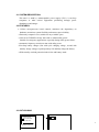
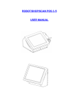
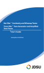
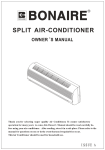
UPS
Uninterruptible Power System
UPS-200/250/400
USER MANUAL
66P-S025-036
TABEL OF CONTENTS
1.IMPORTANT SAFETY INSTRUCTIONS … … … … … … … … … … … … . . 1
2.INTRODUCTION … … … … … … … … … … . . … … … … … … … … … … … … … . 5
2.1 SYSTEM DESCRIPTION … … … … … … … … … … … … … . … … … . … … … 5
2.2 FEATURES … … … … … … … … … … … … … … … … … … .. … … … … … … … 5
2.3 OUTLOODING … … … … … … … … … … ... … … … … … … … … … … … … … 6
3.INSTALLATION AND OPERATION … … … … … … … … … … … … … … … . . 7
3.1 SITE SELECTION … … … … … … … … … … … … … … … … … … … … … … . 7
3.2 UNPACKING … … … … … … … … … … … … … … … … … … . . … … … … … … 7
3.3 CONNECTING THE UPS … … … … … … … … … … … … … . … … … … … … 7
3.4 SARTING OPERATION … … … … … … … … … … … … … … … … … … … … 8
3.5 BACK UP OPERATION … … … … … … … … … … … … … .. … … … … … … . . 8
4.MAINTENANCE … … … … … … … … … … … … … … … … … … … … … … . . … 9
5.TROUBLESHOOTING … … … … … … … … … … … … … … … … … … … … … … 9
6.BATTERY REPLACEMENT … … … … … … … … … ... … … … … … … … . … … 1 0
7.STORAGE … … … … … … … … … … … … … … … … … … … … … … … … … … … 11
8.SPECIFICATIONS… … … … … … … … … … … … … … … … … … … … … … . . … 12
2
1. IMPORTANT SAFETY INSTRUCTIONS,
SAVE THESE INSTRUCTIONS
1.1 • This manual contains important instructions for Model UPS series that should
be followed during installation and maintenance of the UPS.
• Unplug the unit from the AC outlet and make certain of all switches are
in the “off” position before cleaning. Do not use liquid or aerosol
cleaners, use only a water dampened cloth for cleaning.
• Do not attempt to service this product by yourself. Opening or removing covers
may expose you to dangerous voltage. Return the unit to your dealer for proper
handling.
• The output receptacles may have high voltage even the unit is not connected to
wall power.
• If the fuse is opened, to reduce the risk of fire, replace only with the same type
and rating of fuse.
• Servicing of battery should be performed by personnel knowledgeable of battery
and the required precautions. Keep unauthorized personnel away from battery.
3
1.2 SAFETY
CAUTION:
l
l
l
l
This unit is should be installed from service personnel.
The equipment can be operated by any individuals with no previous
experience.
The socket-outlet shall be installed near the equipment and easily accessible.
Attention, hazardous through electric shock. Also with disconnection of this
unit from the main, hazardous voltage still may be accessible through supply
from battery. The battery supply should be therefore disconnected in the plus
and minus pole through the from the outer enclosure accessible battery fuses
when maintenance of service work inside the UPS is considered.
2. INTRODUCTION
4
2.1 SYSTEM DESCRIPTION:
This unit is a stand by uninterruptable power supply (UPS.), it can keep
computers or other critical equipments performing through power
disturbances and outages.
2.2 FEATURES:
• Utilizes microprocessor based controls, minimizes the dependency on
hardware, maximizes system flexibility and assures super reliability.
• Extremely compact in size, suitable for any available space.
• Unit can be TURNED ON any time with or without utility power.
Suitable for emergency applications, especially during utility power failure.
• Automatic frequency selection to mate with utility power.
• Two-Step battery charger (first with cyclic charging voltage; second with
stand by charge voltage) to prolong battery life and fully charge the battery.
• With actually overload protection both in line and battery mode.
2.3 OUTLOOKING
OVER LOAD
LINE NORMAL
2
BAT. IN USE
5
MODEL-UPS-250
1
UPS-200/250/400 Front Side View
1 BRAND NAME
UPS-200/250/400 Rear Side View
2 POWER SWITCH
3 OUTLET SOCKET
4 INLET SOCKET
3 INSTALLATION AND OPERATION
3.1 SITE SELECTION
6
This unit can be installed besides the computer or equipment, do not install it
in non-ventilated areas.
3.2 Unpacking
The following items are included in the carton
l
User’s manual.
l
Power cord.
l
UPS
3.3 Connecting the UPS
For UPS series: Use the power cord to connect the wall power (utility power)
and inlet socket. Connecting the power cord of your computer to the UPS
output receptacle.
3.4 Staring operation
3.4.1
Turn on the UPS by pressing switch on rear panel to “ON” position, the
LED will light up, if the line voltage is absent, the LED will be slowly
7
flash and buzzer will be slowly beeping.
3.4.2 Turn on the computer, if it is over loaded, the LED and buzzer will
rapidly flash and beep, you should check the power rating of the loaded
equipment then remove the less critical one. Generally, the total power
consumption of one set of personal computer (color monitor) will not
exceed the rating of this UPS.
3.4.3 Unplug the input power cord to test the UPS backup function.
The LED and buzzer will be slowly flash and beeping. The computer or
other equipment shall still work well, without any malfunctions or
reset action.
3.4.4 Reapply the line power to the UPS, the UPS shall return to line mode
in 2 seconds.
3.4.5 Keep line power applied continuously to the unit for at least 5 hours to
ensure battery is fully charged.
3.5 Backup operation
If the line power is outage or input voltage is too high or too low, the UPS
will transfer to battery mode. The back up time should be about 10 minutes
for one set computer, if the back up time is less than 3 minutes, and the UPS
have been long time charged, the battery is not good enough and better to
replace with a new one.
4 MAINTENANCE
The unit is designed for years of trouble-free operation, so only a little maintenance
is required.
8
A few helpful hints:
-Periodically vacuum dust from ventilation openings.
-Occasionally wipe exterior with a damp cloth.
5 TROUBLESHOOTING
If the UPS fails to operate properly, please check the following
TROUBLESHOOGING CHART. If the unit is to be returned for service, please
note the following information and pack it in the original carton .
a. model number, serial number.
b. Date of purchase.
c. Full description of problem.
TROUBLE SHOOGING CHART
PROBLEM
UPS not on
LED not light
POSSIBLE CAUSE
ACTION TO TAKE
main switch not on
turn on the main switch
battery failure battery voltage replace or recharge the battery call
less than 10V
for service
PC board failure
replace the PC board, call for
service
UPS always at battery power cord lose
replug the power cord.
mode
AC fuse burn out
replace the AC fuse
Line voltage too high, too low or normal condition
black out
PC board failure
replace PC board, call for service
Back up time too short battery not fully charged
recharge the UPS at least 4 hr.
PCB failure
replace the PC board, call for
service
LED rapidly blinking over load
remove the least critical load
Buzzer rapidly beeping
6 BATTERY REPLACEMENT
Your battery should run any where from 3-5 years before eve needing to be
replaced.
Please follow the instructions below for easy battery replacement.
9
1) Unplug unit from AC power source and disconnect all connected equipment.
2) Disconnect AC power cord from unit.
3) Turn unit upside down and using a phillips screws driver, unscrew the 4
screws holding the top of the unit to bottom. Put screws in a safe place for
reconnection.
4) Holding the top together firmly with the bottom, turn the entire unit right
side up.
5) Carefully lift top cover off and place to the side. The connecting wires and
electronics will be exposed. Be careful not to touch any inner components
when changing the battery.
6) Remove the 2 connecting wires from the battery.
7) You can now easily remove the battery from the unit
CAUTION: Do not dispose of battery in fire.
CAUTION: Do not attempt to open the battery.
CAUTION: The following precautions should be taken when replacing the
battery
l Remove watches, rings, etc …..
l Use tools with insulated handles
8) Place your new battery in the same position/direction and reconnect the
wires red wire-position(+) and black wire negative(-)
9) Please follow steps 5.4 and 3 (in that order) to reconnect the entire unit.
10)Please follow manual instructions in order to properly reconnect your
equipment.
7 STORAGE
7.1 Storage conditions
Store the UPS covered and upright in a cool, dry location, with its battery fully
10
charged. Before storing, charger the UPS for at least 4 hours. Remove any
accessories in the accessory slot and disconnect any cables connected to the
computer interface port to avoid unnecessary draining the battery.
7.2 Extended storage
During extended storage in environments where the ambient temperature is –15
to +30℃(+5 to +86℉),charge the UPS’s battery every 6 months.
During extended storage in environments where the ambient temperature is +30
to +48℃(+86 to +118.4℉), charge the UPS’s battery every 3 months.
8. SPECIFICATIONS
MODEL
INPUT
OUTPUT
Capacity
Voltage
Frequency
Voltage (on battery)
UPS200
UPS-250
UPS-400
200VA
250VA
400VA
100V,115V,230V
50 or 60 Hz +/-5% (auto sensing)
Simulated sine wave at Line Input +/-5%
11
Frequency
(on battery)
Transfer Time
Spike Protection
Overload Protection
50 or 60 Hz +/-2%
2/4 milliseconds, including detection time
320 joules, 2ms
UPS automatic shutdown if overload exceeds 110% of
nominal at 60 seconds and 130% at 3 seconds.
Unit Input
Fuse for overload & short circuit protection
Short Circuit
UPS output cut off immediately or input fuse protection
BATTERY
Type
Sealed, maintenance-free lead acid
Typical Recharge Time 4 hours ( to 90% of full capacity)
Back up Time
3-30 minutes (depending on computer load)
PHYSICAL
Net Weight kg (lbs)
5.0 (11)
5.5 (12)
6.0 (13)
Shipping Weight kg
5.5 (12)
6.0 (13)
6.5 (14)
(lbs)
Dimension (mm)
97 x 260 x 135
WxDxH
Input Inlet
IEC 320 power inlet
INDICATOR
Line normal
Steady ON of green LED
Battery in use
Slow blinking of green LED (about 0.47Hz)
Battery low
Fast blinking of green LED (about 1.825 Hz)
Over low
Very rapid blinking of green LED (about 3.75 Hz)
between 110% to 130% load.
ALARM
Battery in use
Slow beeping sound (about 0.74 Hz ) 1 minute
Battery low
Medium beeping sound (about 1.825Hz)
Over load
Rapid beeping sound (about 3.75 Hz) within 110%
to130% load.
CONFORMANCE Safety
cUL, TUV, CE, meet FCC
Surge
Meet IEEE 587 standard
ENVIRONMENT Ambient operation
3,500 meters max. elevation, 0-95% humidity noncondensing 0-48 deg C
Audible noise
<40 dBA (1 meter from surface )
Storage condition
15000 meters max. elevation
©1999 Powercom Co., Ltd. All right Reserved. All trademarks are property of their respective owners.
Specifications subject to change without notice.
PROTECTION
and FILTERING
12