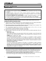
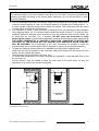
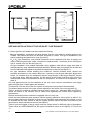
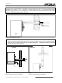
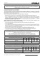
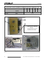
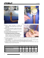
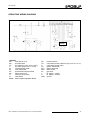
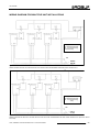
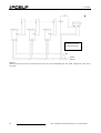
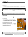
1
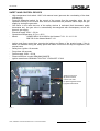
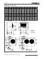
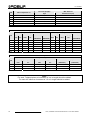
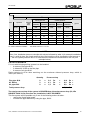
Installation, use and
maintenance manual
Heaters Line F1 Series
Gas fired unit heaters
for heating medium-large areas
Natural gas/LPG fired
Ed. 05/2009
F1 GAS FIRED UNIT HEATERS
TABLE OF CONTENTS
SECTION 1 GENERAL WARNINGS: .................................................................page
3
SECTION 2 GENERALITY AND CHARACTERISTICS:.....................................page
4
Operation of the unit....................................................................................page
4
Constructive characteristics ........................................................................page
4
Safety and Control devices .........................................................................page
5
Technical Characteristics ............................................................................page
6
Dimensions .................................................................................................page
7
SECTION 3 INSTALLATION: .............................................................................page
8
General rules...............................................................................................page
8
Size and installation of the air inlet/flue exhaust..........................................page 10
Support bracket installation .........................................................................page 16
Installation of Remote control box ...............................................................page 16
Burner pressure adjustment ........................................................................page 17
Conversion to another type of gas ..............................................................page 18
Operating Wiring diagram ...........................................................................page 20
Installation Wiring diagram ..........................................................................page 21
Wiring Diagram for Multiple unit installation ................................................page 22
SECTION 4 USE AND OPERATION: .................................................................page 24
Start and Stop of the unit ............................................................................page 24
SECTION 5 MAINTENANCE AND SERVICING:................................................page 26
Removable burner ......................................................................................page 26
Operating failures........................................................................................page 27
Types of failures and servicing series .........................................................page 27
Case N°1 - The units locks out during the first ignition phase.............page 27
Case N°2 - The units locks out during operation ................................page 27
Case N°3 - Temperature limit thermostat (M1) stops the burner ........page 28
Case N°4 - The burner goes out and does not re-ignite even
if the room thermostat requires it ....................................page 28
Case N°5 - The exhaust fan will not start............................................page 28
Case N°6 - The exhaust fan starts but the unit does not ignite...........page 28
Troubleshooting Flow Chart ........................................................................page 29
Ed. 05/2009
2
User, Installation and Service Manual for F1 Gas Unit Heaters
Ed. 05/2009
SECTION 1 - GENERAL WARNINGS
-
-
-
-
-
•
•
•
•
This manual is an integral and essential part of the product and must be given to the user.
Qualified service engineers are those having specific technical experience in the field of
heating installation unit for domestic and industrial use. In the case of any doubt,
contact your local agent or Manufacturer.
This unit must be exclusively used for the purpose it was intended. Any other use is to be
considered improper and therefore dangerous.
The manufacturer will not be held responsible for damages resulting from installation errors or
failure to comply with the manufacturer’s instructions.
Do not obstruct the fan intake opening or the air delivery grids.
In case of failure and/or poor operation, isolate the unit (disconnect it from the power supply
and close the main gas cock), do not attempt any repair or direct servicing.
Call qualified service engineers only.
The manufacturer’s authorised service centres using only original spare parts must only carry
out any repair to the products.
Misapplication of the above might compromise the safety of the unit.
To ensure unit efficiency and correct operation, it is essential that qualified service engineers
carry out annual maintenance following the manufacturer’s instructions.
Should the unit be sold or transferred to another owner, please ensure that the manual
remains with the unit for use by the new owner and/or installer.
Before turning the heater on, a qualified service engineer must check:
• that electric and gas supply ratings are the same as those given in the data plate.
• that the exhaust duct operates correctly.
• that combustion air feed and exhaust occur correctly according to the existing standards.
• the internal and external tightness of the pass supply line.
• fuel flow control according to the heater’s power requirements.
• that the heater is supplied with the type of fuel for which it is pre-set.
• that the gas supply pressure is within rating limits.
• that the gas supply system is suitable to the heater and all safety and check-over devices
prescribed by existing standards are duly installed.
Do not use gas pipes to ground the appliance, or any other electrical appliance.
Avoid unnecessary supply when unit is not in use and always close the main gas cock.
If the appliance is turned-off for a longer time period, close the main gas supply cock and cut
off the electrical supply.
WARNING!
If you smell gas
do not operate electric switches, telephones or any other object or device which may cause
sparks;
open immediately doors and windows to create a cross-current of air to purify the room;
shut-off the gas supply;
call for a qualified service engineer
Installation, Start-Up and Service Manual for F1 Gas Unit Heaters
3
Ed. 05/2009
SECTION 2 - GENERALITY AND CHARACTERISTIC
OPERATION OF THE UNIT
- The F1 gas fired air heater is an independent heater appliance with airtight combustion circuit
and forced air draft.
- It’s designed for an indoor installation - inside the area to be heated.
- It’s adjustable for the use of Natural Gas (G20) or LPG (G30/G31).
- The combustion circuit is airtight regarding heated room and conforms the standard EN 1020 for
the C type appliances: the air inlet of the combustion air and the flue exhaust are outdoors and
are ensured through the operation of combustion blower. The appliance is certified either for the
B type installations, where is allowed combustion air inlet from indoors (from the area to be
heated).
- A room thermostat, (not supplied with the unit) controls the heater operation.
- When the thermostat is turned on the flame control box, after the pre-purge period (about 40
seconds), ignites the burner.
- The flame sensor controls the ignition of the burner. If the flame does not appear the flame
control unit locks out the heater:
- The combustion products pass through the heat exchangers, the air flow given by the axial fan
provides warm air to the room.
- The airflow direction is regulated by means of adjustable louvres. A ‘’vertical louvres kit’’ is also
available on request for horizontal regulation of the airflow.
- The fan control thermostat allows the axial-flow fan to start automatically only when the heat
exchangers are hot and to turn off when they are cold. This prevents cool air being blown into
the room
- If heat exchangers overheat due to malfunction, the temperature limit thermostat cuts off the
supply to the gas valve, thus interrupts fuel flow and turns off the main burner
NOTE
After removing the cause of overheating, Qualified service engineer should carry out resetting of
the temperature limit thermostat,
- Ahead of the burner is installed the flue fan which makes the air-gas mixture and forces draft of
the exhaust flues.
- In case of obstructions in the intake duct or flue fan malfunction, a differential pressure switch
closes the gas valve and consequently stops fuel flow to the burner.
- In the summer time it’s possible to activate only the axial fan to provide pleasant and refreshing
air movement in the room. (see Section 4 - Paragraph “Summer”).
CONSTRUCTIVE CHARACTERISTICS
- premix burner made of stainless steel
- high head blower; models F1 51/61/81 are provided with electronic board that controls and
guarantees constant speed of the blower;
- cylindrical combustion chamber made of stainless steel
- heat exchanger patented by Robur made of special aluminium alloy, fining horizontally on the
air side and vertically on the flue side with extremely high capacity of thermal exchange
- insulated steel casing painted with epoxy powders
- axial fan with high air flow capacity
- according to the norms in force regarding the radio interference
- heat recovering post-ventilation
4
User, Installation and Service Manual for F1 Gas Unit Heaters
Ed. 05/2009
SAFETY AND CONTROL DEVICES
-
-
-
High temperature limit switch: 100°C with manual reset (prevents the overheating of the heat
exchangers)
Pressure differential switch: for the control of the correct flue fan operation; when fan not
operates correctly or the flue/air inlet ducts are obstructed the pressure switch stops the gas
supply by closing the gas valve.
Gas valve: in the case that one of the safety devices is activated (limit thermostat, safety
thermostat etc.) the gas valve is automatically de-energised with contemporary cut-off the
burner’s gas supply.
Electrical supply: 230 V – 50 Hz
Operational temperature: 0°C to + 60°C
Model:
HONEYWELL VK 4125A for the Heaters F1 21. 31. 41. 51. 61
BM 762 for the Heater Model F1 81
Ignition and flame control box: controls the ignition and flame of the premix burner; if the is
flame not detected during the safety period the flame control box will stop the appliance; with
manual reset.
Safety time: ignition 10 seconds
Purge time: 40 seconds
Power supply: 230V – 50 Hz
Flame control box model: BRAHMA CM32PR
Ignition transformer: BRAHMA TC2LTCAF / EICHHOFF 4718/2
C
B
A) flame control box
B) pressure switch
C) fuse 6,3A 5x20
D
A
D) speed regulation board
E) ignition transformer
E
Figure 1
User, Installation and Service Manual for F1 Gas Unit Heaters
5
Ed. 05/2009
TECHNICAL CHARACTERISTICS
MODEL
UNIT
F1 21
F1 31
F1 41
Appliance Category
Nominal heat output
kW
23,08
30,77
37,15
48,35
61,32
77,14
BTU
78804
105046
126841
165072
209357
263369
kW
21
28
33,8
44
55,8
70,2
BTU
Efficiency (5)
Nominal air flow (1)
Temperature rate
71698 95597
115407 150224 190520 239668
%
91
91
91
91
91
91
3
m /h
2000
2700
3400
4200
5200
7800
K
31,1
30,7
29,5
31
31,8
26,7
Natural Gas
m3/h
2,43
3,25
3,93
5,11
6,49
8,16
LPG
LPG
kg/h
1,80
2,42
2,93
3,81
4,84
6,09
kg/h
1,78
2,38
2,87
3,74
4,75
5,97
640
900
G30
G31
Natural Gas
LPG. G30
LPG G31
20
mbar
30
"
37
3/4F
air
mm
80
flue
mm
80
Diameter gas inlet
Pipe Diameter
F1 81
C13 - C33 - B23 - C63 - C53
Nominal heat input (5)
Inlet gas pressure
F1 61
II2H3+
Appliance type
Gas Consumption (2)
F1 51
Voltage
230V - 50Hz
Wattage
W
260
400
450
Operating temperature
°C
Fuse
A
Throw
(residual air speed >1m/s) (3)
m
14
16
20
22
25
29
dB(A)
41
43
44
46
47
49
dB(A)
53
55
56
57
60
63
kg
55
59
68
80
90
108
Noise level 6 m distance
in free field
in tipycal installation
Weight
0° +35°
(4)
6,3
Table 1
1
At 20°C - 1013mbar
2
At 15°C - 1013mbar
3
THROWS FOR GUIDANCE ONLY. THROW DEPENDS ON HEIGHT OF THE BUILDING, MOUNTING HEIGHT OF THE HEATER, ROOM TEMPERATURE AND LOUVRE
SETTING.
4
WARNING: THE ROOM OPERATIONAL TEMPERATURE IS BETWEEN 0° AND +35°C ;THE APPLIANCE’S COMPONENTS OPERATIONAL TEMPERATURE IS BETWEEN
0° AND +60°C
5
3
DATA REFERED TO THE LOW HEAT VALUE (9,45 kWh/m - 15°C 1013 mbar)
WITH THE AIM OF CONTINUOUSLY IMPROVING THE QUALITY OF ITS PRODUCTS, THE
MANUFACTURER RESERVES THE RIGHT TO VARY ABOVE INFORMATION WITHOUT ANY PRIOR
NOTICE.
6
User, Installation and Service Manual for F1 Gas Unit Heaters
Ed. 05/2009
DIMENSIONS OF THE UNITS
A
B
C
D
E
F
G
H
J
L
N
F1 21
630
640
800
490
370
405
440
430
120
285
95
F1 31
630
640
800
490
370
405
440
430
120
285
95
F1 41
770
670
800
490
510
405
580
430
120
285
95
F1 51
880
700
800
490
620
405
690
430
120
285
95
F1 61
1070
640
800
490
810
405
880
430
120
285
95
F1 81
1270
700
800
490
1010
405
1080
430
120
285
95
P
Q
R
S
T
U
V
W
X
Y
Z
F1 21
390
435
340
600
720
90
3/4
-
80
80
355
F1 31
390
435
340
600
720
90
3/4
-
80
80
355
F1 41
460
435
340
600
720
90
3/4
-
80
80
410
F1 51
515
435
340
600
720
90
3/4
-
80
80
410
F1 61
398
435
340
600
720
90
3/4
432
80
80
355
F1 81
468
435
340
600
720
90
3/4
495
80
80
410
FRONT
VIEW
VISTA
FRONTALE
RIGHT
SIDE
VIEW
VISTA
LATO
DESTRO
H
C
Q
L
F
D
B
Bmaximum
massima
T
2
Y
X
E
G
A
1
3
Z
S
2
1
Z
T
S
R
R
V 4
X
Y
N
U
V
J
4
P
REAR
VIEW
VISTA
POSTERIORE
F1 21-31-36-41-51
N
U
J
P
W
REAR
VIEW
VISTA
POSTERIORE
F1 81-61
IM3050
3
11. SCARICO
FUMI
Flue Exhaust
2 PRESA ARIA
2.COMBURENTE
Air Supply
33. INGRESSO
CAVO
Power Line
4.DI ALIMENTAZIONE
Gas Connection
4 ATTACCO GAS
Figure 2
User, Installation and Service Manual for F1 Gas Unit Heaters
7
Ed. 05/2009
SECTION 3 - INSTALLATION
GENERAL RULES
-
-
WARNING!
A qualified service engineer following the manufacturer’s instructions must carry out the
installation.
Qualified engineer means those having specific technical competence according to
national/international standards. In any case all necessary information could be obtained
directly by Qualified Engineer or Manufacturer.
An incorrect installation can cause damages to people, animals and property. In case of
erroneous installation, the manufacturer cannot be held responsible for such damages.
The units must be installed according to the national and international norms regarding this
type of appliances and applications.
Install the gas supply lines, the electric power lines and a suitable support bracket for the unit
according the approved installation project.
Installation procedures should be as follows:
A. Unpack the unit, carefully checking that it has not been damaged. Every unit is factory tested before
shipment, therefore, if there are damages, report them immediately to the carrier.
B. The minimum distance from the wall behind the unit must be enough for air circulation. The
minimum distance from the lateral walls is given by Figure 3.
C. The recommended height from the floor to the heater base is 2.5 to 3.5 m. It is not
recommended to install the appliance under the 2.5m height.
D. A gas cock and a pipe union must be provided for gas supply.
E. Make sure that an adequate gas supply from the gas network is provided, particularly if the unit
is supplied with:
Natural gas - G20:
Be sure that the pressure of the gas network, with the unit in operation, is set at 20 mbar (0.29
psig, 8.03 in.WG.) allowed tolerance between 17 and 25 mbar (0.25 to 0.36 psig; 6.9 to 10.0
in.WG.).
LPG (Propane – Butane mix) - G30:
For the first pressure drop required in the supply, it is advisable to install a pressure
governor near the liquid gas tank so as to reduce the pressure to 1.5 bar (22 psig). A
pressure governor for a second pressure drop should be placed near the heater to reduce
the pressure to 30 mbar (0.43 psig; 12.0 in.WG.) allowed tolerance between 20 and 35
mbar (0.29 to 0.50 psig; 8.1 to 14 in.WG.).
LPG (Pure Propane) - G31:
For the first pressure drop required in the supply, it is advisable to install a pressure
governor near the liquid gas tank so as to reduce the pressure to 1.5 bar (22 psig). A low
pressure governor for a second pressure drop should be placed near the heater to reduce
the pressure to 37 mbar (0.43 psig; 12.0 in.WG.) allowed tolerance between 25 and 45
mbar (0.29 to 0.50 psig; 8.1 to 14 in.WG.).
NOTE: In the case of doubt, adjust the appliance as for the propane- butane mix.
F. Carry out the electrical connections according to the installation wiring diagram (see figure 19),
checking that the voltage supply is 230/50Hz single-phase. For this operation make sure that:
- all electrical supply parameters are according to those required on the type plate of the appliance.
- wire type is H05 VVF 3x1 mm2 with a maximum external diameter of 8.4 mm.
- when connecting, ensure that the earth wire is longer than the live wires, so that it will be the last
wire to break if the supply cable is stretched, thus ensuring a good earth continuity.
8
User, Installation and Service Manual for F1 Gas Unit Heaters
Ed. 05/2009
NOTE
The electrical safety of the unit is attained only when the unit itself is correctly connected and
efficiently grounded according to the existing safety standards. Do not use gas tubes to earth
electrical apparatus.
G. The unit should be connected to the electric supply line by means of an omnipolar switch with a
minimum contact opening of 3 mm. An omnipolar switch is a '’Double pole isolating switch’’, i.e.
a switch capable of disconnecting both on phase and neutral. This means that when the switch
is opened, both contacts are disconnected.
H. It is mandatory to install a room thermostat connected to the unit according to the installation
wiring diagram (figure 19). It is recommended to place the sensor at about 1.5 m from the floor,
protected against air draughts, direct exposure to sun rays and direct heat sources (lamps, hot
air flows from the unit itself, etc.). If possible, DO NOT place the thermostat on walls
bordering the outside, to avoid false temperature readings and therefore system operation. IF
THE ROOM THERMOSTAT IS PROPERLY INSTALLED, UNWANTED STARTING AND
STOPPING OF THE SYSTEM WILL BE AVOIDED AND ADEQUATE ROOM COMFORT
WILL BE ENSURED. As an alternative to the room thermostat it’s possible to install the
programmable remote control which could be supplied on request as an optional accessory.
I. To obtain the maximum system efficiency it is advisable to comply with the following rules:
- Install units as close as possible to the work area, taking care that the air flow does not come
directly into the contact with people.
- Take obstacles into consideration (columns, etc.)
- For better heat distribution in the case of multiple unit installation, create alternate flows of hot
air (see figure 4).
- In some cases it may be suitable to place the units close to the main doors, so they can
operate as an air barrier when doors are opened.
min
0,2m
0,2 m
min 0,4
0,4 m
min
m
A
A
AA
0,35
2,5 – 3,5 m
2,5 - 3,5 m
A= Lunghezza
del generatore
A= LENGTH OF
THE UNIT
Figure 3
CLEARANCES TO BE RESPECTED
User, Installation and Service Manual for F1 Gas Unit Heaters
9
Ed. 05/2009
Figure 4
POSITION OF THE UNITS
SIZE AND INSTALLATION OF THE AIR INLET / FLUE EXHAUST
F1 Series gas fired unit heaters can be installed as following:
- B23 type installation, combustion air taken directly from the room and flue exhaust gases to the
outside. This exhaust flue duct can be either horizontal or vertical. This type of installation is not
sealed regarding the heated room (see figures 6/7).
- C13 e C33 type installation; room sealed combustion circuit. Appliance with inlet air supply and
outlet of exhaust gases with, either, concentric or separate ducts - horizontal (for C13 see figures
8/9) or vertical ones (for C33 see figure 10).
- C53 type installation: room sealed combustion circuit; appliance with inlet air supply and outlet of
exhaust gases by using separated ducts and terminals n different walls, for example, the air inlet duct
from the wall behind the appliance and the flue exhaust duct on the roof (see figure 11).
- C63 type installation: allows installing the certified air inlet/flue exhaust ducts, elbows and
terminals purchased on the market. Moreover, it permits to use the pipe diameters bigger than
80mm: for example when the installation requires using the pipe of the larger diameter, caused
by the longer ducts. With this typology, for the calculus of the flue/air inlet duct refer to the duct
manufacturers data and furthermore to the flue composition, flue flow and its temperature. (see
table 2).
Use only approved ducts for the installation of the units. Upon request, manufacturer can supply
approved rigid pipes, coaxial pipes and terminals.
To determine a correct size of the flue system its total pressure drop has to be calculated.
The allowed pressure drop in the pipe system depends on the model of the unit (see table 2).
Table 3 shows the maximum allowed pressure drop for each unit - diameters Ø80 and Ø100; it
shows the losses of the exhaust and air intake flues regarding the coaxial ducts supplied by
manufacturer.
External terminals pressure losses are negligible since it is very low.
Check the total inlet/outlet pipes pressure losses regarding maximum values given by table 2. On
the next page follows the example of pressure loss calculation and respective duct project. It must
be checked that the total amount of the flue system pressure losses are within the minimum and
the maximum losses allowed for the unit (see table 2).
Table 4 gives the lengths of the air supply and flue exhaust ducts for different types of installation.
These values are APPROXIMATE for the types of installation shown on the figures 6,7,8,9,10 and
11.
10
User, Installation and Service Manual for F1 Gas Unit Heaters
Ed. 05/2009
Note: When horizontal pipes with lengths above 1 metre are installed, the flue pipe must be
mounted with a slope of 2 to 3 cm each 1 metre length (see fig. 5), to prevent entering the
condense drops into the unit. In addition, to install correctly the flue exhaust and the air intake
terminals, follow the details given in figure 8.
SLOPE
2-3 CM PER METER
Figure 5
SLOPE OF THE HORIZONTAL FLUE PIPE
Note:
When vertical pipes with length above 3 metres are installed, to prevent that condense drops
enter the unit, on base of the vertically mounted flue pipe a T-shaped piece MUST be fitted,
in order to collect the condense.
SIDE VIEW
TOP VIEW
FLUE
AIR
Figure 6
INSTALLATION TYPE B23 WITH WALL TERMINAL
User, Installation and Service Manual for F1 Gas Unit Heaters
Figure 7
INSTALLATION TYPE B23 WITH ROOF TERMINAL
11
Ed. 05/2009
Mod.
Flue Temperature °C
Flue flow (weight)
kg/h
Max. Allowed
Pressure loss (Pa)
F1 21
195
38,2
19
F1 31
197
51,0
25
F1 41
205
61,6
30
F1 51
195
80,0
60
F1 61
198
101,5
80
F1 81
195
127,7
85
Table 2
TECHNICAL DATA FOR PIPES SUPPLIED ON REQUEST BY MANUFACTURER
Component’s pressure loss Ø 80
Mod
Pipe (Pa/m) Elbow 90° (Pa)
Component’s pressure loss Ø 100
Coaxial
Pipe (Pa/m)
Elbow 90° (Pa)
Coaxial (Pa)
Flue
Air
Flue
Air
Wall
(OSCR007)
Roof
(OSCR008)
Flue
Aur
Flue
Air
Roof
(OSCR009)
F1 21
0,9
0,5
1,0
1,0
1,7
2,1
0,2
0,2
0,5
0,5
1,2
F1 31
1,4
0,7
2,6
1,3
3,2
8,7
0,3
0,3
1,7
0,8
5,1
F1 41
2,0
1,0
4,2
1,8
4,9
N.P.
0,6
0,6
2,8
1,3
10,1
F1 51
2,3
1,6
6,5
3,5
N.P.
N.P.
1,3
1,0
5,0
2,5
16,9
F1 61
3,5
2,4
9,9
5,7
N.P.
N.P.
2,1
1,1
7,4
4,7
N.P.
F1 81
9
3,4
14,8
11,0
N.P.
N.P.
2,5
1,4
10,9
8,1
N.P.
Table 3
N.P.: INSTALLATION NOT POSSIBLE
N.D.: INSTALLATION NOT AVAILABLE
TECHNICAL DATA FOR PIPES Ø 130 SUPPLIED ON REQUEST BY MANUFACTURER
Component’s pressure loss Ø 130
Pipe (Pa/m)
Mod
Elbow 90 (Pa)
Coaxial (Pa)
Flue
Air
Flue
Air
Roof
(OKTC001)
Wall
(OKTC004)
F1 51
0,8
0,2
2,8
1,2
14
14
F1 61
1,1
0,3
3,2
1,4
19
19
F1 81
1,4
0,5
4,2
1,8
25
25
Table 3A
Note:
For each T-shaped piece an increment of 3 m in length should be added.
For each 45o elbow an increment of 1,2 m in length should be added.
12
User, Installation and Service Manual for F1 Gas Unit Heaters
Ed. 05/2009
MAXIMAL PIPE LENGTH BY VARIOUS INSTALLATION
Type of Installation
B 23
C 13
C 33
Coaxial pipe wall
Pipe Ø 80
Mod
Separate
pipe
Ø 80
C 53
Coaxial pipe Roof
Ø 125
(OSCR007)
Ø 180
(OKTC004)
Ø 125
Ø 150
(OSCR008) (OSCR009)
Ø 210
(OKTC001)
pipe
Ø 80
pipe
Ø 130
pipe
Ø 80
pipe
Ø 100
pipe
Ø 130
pipe 80
Horiz.
Verti.
flue
flue
air/flue
air/flue
air/flue
air/flue
air/flue
air/flue
air/flue
F1 21
21
16
13+13
12+12
N.D.
8+8
15+15
N.D.
1+15
F1 31
17
14
11+11
10+10
N.D.
5+5
7+7
N.D.
1+14
F1 41
15
11
10+10
8+8
N.D.
N.P.
4+4
N.D.
1+12
F1 51
25
23
14+14
N.P.
15+15
N.P.
8+8
15+15
1+15
F1 61
20
18
11+11
N.P.
12+12
N.P.
6+6
15+15
1+14
F1 81
8
6
5+5
N.P.
10+10
N.P.
n.r.
14+14
1+6
Table 4
N.P.: INSTALLATION NOT POSSIBLE
N.D.: INSTALLATION NOT AVAILABLE
NOTE
When Your installation does not coincide with values indicated by table 4 (for example installation
type C13 with air pipe 10m length and flue pipe 16m length) must be checked the total amount of
the flue system pressure loss. It is to be within the maximum loss allowed for the unit (see
example below).
CALCULUS EXAMPLE
F41 unit with following air/flue system is to be installed:
- 8 meters of flue pipe Ø 80
- 2 elbows 90° Ø 80 on the flue pipe
- 8 meters of air pipe Ø 80
Piping calculus is to be done watching out the maximum allowed pressure drop, which is
30Pa (see table 2).
Flue pipe Ø 80
90° Elbow
Air pipe Ø 80
Quantity
Pressure drop
8
x
2,0
Pa
=
2
8
Total pressure drop
x
x
4,1
1,0
Pa
Pa
=
=
16,0
Pa +
8,4
8,0
Pa +
Pa =
32,4
Pa
The total pressure drop of the system is BIGGER than allowed pressure drop (32,4 Pa
HIGHER THAN 30 Pa), therefore the installation is NOT POSSIBLE.
This flue system will be possible only if one of the following actions is taken:
- reduce the flue/air pipe length
- Increase the pipe diameter by using the pipe, Ø100
User, Installation and Service Manual for F1 Gas Unit Heaters
13
Ed. 05/2009
TOP VIEW
TOP VIEW
F
A
D
E
F
F1 Unit Heater
Pipe Ø 80
Pipe Ø 80
Coaxial Pipe
flue
D
E
A
Cod. P3370
air
Figure 8
Figure 9
C13 INSTALLATION WITH SEPARATE WALL TERMINAL
C13 INSTALLATION WITH COAXIAL WALL TERMINAL
SIDE VIEW
Figure 10
Figure 11
C33 INSTALLATION ROOF COAXIAL TERMINAL
C53 INSTALLATION WITH ROOF FLUE TERMINAL AND WALL AIR SUPPLY
PIPE
14
User, Installation and Service Manual for F1 Gas Unit Heaters
Ed. 05/2009
RECOMMENDED
1
ALLOWED
2
1
2
2
FORBIDDEN
1
1 = FLUE
2 = AIR SUPPLY
Figure 12
WALL TERMINAL POSITION
Note: If the total length of the flue system exceeds 8 metres, it is advisable to contact the Authorised
Engineer or Manufacturer.
User, Installation and Service Manual for F1 Gas Unit Heaters
15
Ed. 05/2009
SUPPORT BRACKET INSTALLATION
Manufacturer supplies an optional, easy-to-install bracket, specifically designed for each heater.
Should you wish not to use these accessories, please refer to the diagram below. Fasten the unit
to the support brackets using four M10 bolts.
FRONT VIEW
Model
A
F1 21
370
F1 31
370
F1 41
510
F1 51
620
F1 61
810
F1 81
1010
840
SIDE VIEW
2,5 - 3,5 m
Figure 13
SUPPORT BRACKETS
INSTALLATION OF REMOTE CONTROL BOX
F1 Series appliances are supplied with remote control box, equipped with summer/winter switch,
lockout lamp and the reset button (see figure 23). The remote control must be wired according the
norms and installed at suitable position. The wiring numeration between 1 – 7 must be respected.
The wiring n° 4 and 8 are not connected (free).
WARNING!
Qualified personnel must carry out this operation. Before performing this operation, cut off the
electrical supply. The section of every cable core to be used for this operation must be1 mm2.
To install the remote control box proceed as follows:
- Isolate the unit from power supply.
- Fix the control box in the desired position (maximum distance 20 metres from the gas unit
heaters) using expansion bolts.
- Mount the supplied cable of cable with 8 x 1 mm2 section (maximum length 20 meters). In
the case you need longer cable than the supplied one, please contact your local dealer or
Robur SpA.
- Connect the control box to the cable.
- Connect the cables of the terminal board inside the unit following the indications given in the
installation diagram (see figure 19)
- Connect the power supply
- Start the unit.
- Check that, when the gas supply is cut off, the lock out warning light C on the control box
lights up (see figure 23). This operation takes about 40 seconds.
- Press reset button C and check that the unit restarts and the light goes out.
- Press the button A ( ) in order to control the correct operation of the summer/winter
function (the burner remains off while the fans are running).
16
User, Installation and Service Manual for F1 Gas Unit Heaters
Ed. 05/2009
Note: The control cables (specially those linked to the remote control and to the temperature
probe) must be kept far away from electrical cables this can be done using e.g shielding or
separate pipes for the two types of cables.
BURNER PRESSURE ADJUSTMENT
For correct operation, the burner pressure must be as given in table n°5, n°6 and n°7. The burner
gas pressure of each unit is set at the factory and is shown by the labels on the package and by a
label inside the control panel of each unit.
In the case the pressure adjustment is necessary keep in mind that:
- Natural Gas: the pressure is to be adjusted by turning the adjustment screw A (figure 14)
- LPG: the adjustment screw is to be screwed down completely to the stop in order to put the
pressure regulator out of operation. The reduction of the pressure from the mains is possible by
adjusting the low pressure governor installed on the gas supply line (see section 3 – General
rules for unit installation - page 6 item E).
Before adjustment of the burner pressure identify TYPE OF THE GAS VALVE installed in the
appliance (see figure 14), than proceed as following:
- Connect the manometer to the gas pressure tap E after unscrewing valve setting screw;
- Turn on the appliance;
- Turn clockwise/counterclockwise the setting screw A in order to set the required pressure value.
When LPG gas used turn completely the setting screw A, and if the pressure needs an ulterior
correction adjust the low pressure gas governor.
- Disconnect the manometer and close the gas tap by tightening adjustment screw.
- Two or three times turn on and turn off appliance to verify the correct and stabile adjustment.
- If necessary it’s possible to check the inlet pressure from the gas tap B.
WARNING!
• After setting the gas pressure, stop and start the unit, and check that burner pressure has
stabilised. If necessary perform a new adjustment.
• After completing the gas pressure adjustment, seal the valve setting screw.
• Check the gas leakage using the water/soap foam or other suitable method.
BURNER PRESSURE SETTING TABLE MODELS SERIES F1
SUPPLIED WITH NATURAL GAS (G20) (GAS SUPPLY PRESSURE 20 mbar)
Burner Pressure
(mbar)
(mmH2O)
CO2 in flue
(%)
CO in flue
(ppm)
F1 21
F1 31
F1 41
F1 51
F1 61
F1 81
10,5
107
9,3
95
9,6
98
8,0
81
8,3
85
7,0
71
8,6 – 9,4
8,8 – 9,2
0 - 30
Table 5
BURNER PRESSURE SETTING TABLE FOR UNITS
SUPPLIED WITH LPG (G30) BUTANE OR COMMERCIAL MIX (SUPPLY PRESSURE 30 mbar)
Burner Pressure
(mbar)
(mmH2O)
CO2 in flue
(%)
CO in flue
(ppm)
F1 21
F1 31
F1 41
F1 51
F1 61
F1 81
28,5
290
28,5
290
28,5
290
27,8
283
28,0
285
26,5
270
10,2 – 11,0
10,5 – 11,0
0 - 30
Table 6
User, Installation and Service Manual for F1 Gas Unit Heaters
17
Ed. 05/2009
BURNER PRESSURE SETTING TABLE FOR UNITS
SUPPLIED WITH LPG (G31) PROPANE OR COMMERCIAL MIX (SUPPLY PRESSURE 37 mbar)
Burner Pressure
(mbar)
(mmH2O)
CO2 in flue
(%)
CO in flue
(ppm)
F1 21
F1 31
F1 41
F1 51
F1 61
F1 81
36,5
372
36,5
372
36,5
372
35,5
362
35,5
362
33,3
339
10,1 – 10,9
10,4 – 10,9
0 - 30
Table 7
VALVOLA
SIT 830 TANDEM
B
A
E
A) burner pressure adjustment
screw (by BM 762 the protection must be
removed)
B) Inlet gas pressure check tap
E) Burner pressure check
B
HONEYWELL VK 4125A
A
E
B
E
A
VALVOLA BM 762
Figure 14
18
User, Installation and Service Manual for F1 Gas Unit Heaters
Ed. 05/2009
CONVERSION TO ANOTHER TYPE OF GAS
WARNING!
Qualified engineers must carry out this operation. Wrong and careless assembly of the gas circuit
may cause dangerous gas leakage. Use adequate seals for all connections.
If the type of gas on the identification label does not correspond to the one that will be used, the
unit must be converted and adapted to the type of gas you wish to use.
For this operation proceed as follows:
A) Cut off power and gas supply.
B) Take off the hexagonal ring nut which clamp the gas pipe to the nozzle support (see figure 15).
Pay the attention to the internal round gasket, don’t lose or damage it.
User, Installation and Service Manual for F1 Gas Unit Heaters
19
Ed. 05/2009
Figure 15
Figure 16
C) Loosen, without removing, 4 screws for
fastening the gas supply pipe to the gas valve
(figure 16);
D) Shove off the gas pipe and take off the nozzle.
If necessary use the screwdriver as to lever it
(see figure 17);
E) Take off the gasket and mount it at the new nozzle
F) Thread the new nozzle at the seat;
G) Re-assembly the gas pipe, Check that the
round gasket inside the ring nut and the
square one at the valve fitting are positioned
correctly. Tight the ring nut whit tightening
torque of 62±2Nm; tight the valve screws;
NOZZLE
Figure 17
H) Proceed then with the adjustment of the unit, as described in previous chapter ‘’Burner
pressure adjustment’’
I) When appliance is on, check for gas leakage with soapy solution or other suitable method.
Check all fittings - even those which were not handled during the operation;
J) Replace the label showing the type of gas for which the unit is set with the other one
indicating the type of gas actually used.
NOZZLES FOR NATURAL GAS AND LPG
F1 21
F1 31
F1 41
F1 51
F1 61
F1 81
Natural Gas (G20) (mm)
Code
4,40
072
5,40
073
6,10
075
8,00
076
9,00
077
11,10
078
LPG (G30-G31) (mm)
Code
2,50
079
3,00
080
3,25
081
3,65
129
4,20
098
4,80
130
Table 7
20
User, Installation and Service Manual for F1 Gas Unit Heaters
Ed. 05/2009
OPERATING WIRING DIAGRAM
BSRB
Figure 18
LEGEND:
M9
fuse 5x20 6.3 A F
M2
fan thermostat
CV
fan capacitor (2 pcs. for F1 61/81)
V
fan motor ((2 pcs. for F1 61/81)
Z1
summer/winter switch
Z9
room thermostat
M1
temperature limit thermostat
M4
flame control unit
L1
lockout warning lamp
P1
reset button
BSRB Blower Speed regulation Board
NP
CS
S
TR
RP7
RP8
Q1
L
N
GND
User, Installation and Service Manual for F1 Gas Unit Heaters
pressure switch
combustion blower capacitor (only for F1 21,31,41)
combustion blower motor
ignition transformer
ignition electrode
flame sensor
gas valve
El. Supply – phase
El. Supply – neutral
ground
21
Ed. 05/2009
INSTALLATION WIRING DIAGRAM
Figure 19
INSTALLATION WIRING DIAGRAM OF F1 SERIES HEATERS (SEE LEGEND FOR FIGURE 18)
22
User, Installation and Service Manual for F1 Gas Unit Heaters
Ed. 05/2009
WIRING DIAGRAM FOR MULTIPLE UNIT INSTALLATIONS
P Programmer
TA ambient thermostat
RL 1-2-3 programming
command relay
GND
230 V
50 Hz
Figure 20
WIRING DIAGRAM FOR MULTIPLE HEATERS INSTALLATION WITH ONE PROGRAMMER AND MORE ROOM THERMOSTATS
Programmer
P P programmatore
TA
ambiente
TA termostato
ambient thermostat
RL1-2-3
comando
RL 1-2-3relè
programming
programmato
relay
GND
230 V
50 Hz
Figure 21
WIRING DIAGRAM FOR MULTIPLE HEATERS INSTALLATION WITH ONE PROGRAMMER AND ONE ROOM THERMOSTATS (MULTIPLE RELAY
SOLUTION)
User, Installation and Service Manual for F1 Gas Unit Heaters
23
Ed. 05/2009
P Pprogrammatore
Programmer
TATAtermostato
ambiente
ambient thermostat
RL relè comando
RL
programming
relay
programmato
GND
230 V
50 Hz
Figure 22
WIRING DIAGRAM FOR MULTIPLE HEATERS INSTALLATION WITH ONE PROGRAMMER AND ONE ROOM THERMOSTATS (ONE RELAY
SOLUTION)
24
User, Installation and Service Manual for F1 Gas Unit Heaters
Ed. 05/2009
SECTION 4 - USE AND OPERATION
START AND STOP OF THE UNIT
WARNING
Qualified service engineer must fulfil the first start-up of the appliance.
Before turning on the heater, a qualified service engineer must check:
• that electric and gas supply ratings are the same as those given in the data plate.
• that the setting is compatible to the heater’s power
• that the exhaust duct operates correctly
• that the gas supply pressure is within rating limits
• that combustion air feed and exhaust occur correctly according to the existing standards.
Winter
1) Set the room thermostat to the highest temperature.
2) Check that the gas cock is open.
3) Supply the unit with electric power by closing the omnipolar switch.
4) Press the button A summer/winter in the position winter
(see figure 23)
5) After the pre-purge period (about 40 seconds), the gas solenoid valve opens and the ignition
electrode begins to sparkle and lights the burner.
6) When flame detected the flame control box is keeping the gas valve opened.
7) Otherwise the flame control unit locks out the heater: the gas supply to the burner is shut off
and a lock-out light C on the reset button B lights up (see figure 23).
8) When default described at item 7) occurs, press the reset button B.
9) If ignition has occurred regularly set the room thermostat to the desired temperature.
WARNING
After a long period of inactivity of the unit or at the first start-up, it may be necessary to repeat the
ignition operation a few times due to the presence of air in the piping.
B
A summer/winter switch:
for the heating, function
winter position
summer position ☼ for the ventilation
B reset button
C lck-out light
☼
A
C
Figure 23
REMOTE CONTROL SWITCH
User, Installation and Service Manual for F1 Gas Unit Heaters
25
Ed. 05/2009
Stop of the unit
-
To turn off the unit, set the room thermostat to the lowest temperature. The burner is turned off,
while the fan will continue to operate until the unit is completely cold.
WARNING
In case of long inactivity, after carrying out the above operation and after the fans have turned off,
close the gas cock and disconnect the electric supply by using the omnipolar switch placed on the
supply line.
NOTE
It is not good practice to turn the unit off by disconnecting the electric power supply, as this may
damage the unit. In fact, this causes the immediate stop of the fans, unit overheating and possibly
the activation of the temperature limit thermostat.
Summer operation
-
Close the gas cock and check the power supply
-
Press the button A in the position summer
and fan will start.
End of the season
- Turn off the appliance and wait the arrest of the fans
- Cut off the gas supply of the appliance
- Cut off the electrical supply if summer ventilation is not
foreseen
Reset of high limit temperature switch
High limit temperature switch stops the burner if appliance
is overheated. It must be reset manually, by pushing the
reset button placed on the rear panel of the appliance
(remove the protection cap first see figure 24). After
resetting replace the protection cap.
RESET BUTTON OF
THE LIMIT SWITCH
Figure 24
WARNING
The activation of the High Limit Temperature Switch indicates ALWAYS the malfunction of the appliance.
In case of frequent stops of the unit please contact Client Support service.
26
User, Installation and Service Manual for F1 Gas Unit Heaters
Ed. 05/2009
SECTION 5 - MAINTENANCE AND SERVICING
REMOVABLE BURNER
The burner mounted inside the F1 Gas Unit Heaters is removable type: this particular construction
characteristic allows the cleaning of the burner.
WARNING
The cleaning of the burner is to be done by qualified personal.
Erroneous or not correct operation of the gas pipeline can cause dangerous gas leakages on
all circuit and particularly on the tamped segment.
To clean the burner proceed as follows:
1. Cut off the electricity and gas supply;
2. Open the side panel of the heater;
3. Demount the hexagonal nut which connect gas pipe and the air blower (see figure 15);
4. Move the gas pipe and remove the gas nozzle (see figure 17);
5. Remove 4 nuts, which fix the casing of air blower;
6. Remove the deflector and gasket;
7. Loose 4 screws which fix the burner, and when the burner is leaned on the bottom unscrew and
remove them completely;
8. Insert a pipe inside the burner (ATTENTION: don’t bend the burner and don’t damage the
deflectors inside the burner) and use the pipe as a lever to pull it up and than to remove the
burner;
9. Clean the burner with compressed air;
10.
Reinsert the burner (MOTE: slot inside the burner must be in the upper position);
11.
Fix the lower screws first and than the upper ones. Cross-tighten the screws;
12.
Reinsert the diaphragm and relative gaskets;
13.
Fix the casing of the air-blower with 4 screws;
14.
Insert the nozzle and gasket in the holder of the nozzle;
15.
Screw tight the hexagonal which fix the gas pipe to the blower;
This procedure is to be applied once in 2/3 years by normal working conditions, or once per year
when there is a lot of impurities in the combustion air (example: “B type” installation of the heater in
factories with welding process).
User, Installation and Service Manual for F1 Gas Unit Heaters
27
Ed. 05/2009
WARNING
Only qualified service engineer authorised by Manufacturer must carry out the operation of
servicing and maintenance.
OPERATING FAILURES
Before looking for possible failures, check:
•
Correct power supply: 230 V ±10%, 50Hz and adequate grounding.
•
Correct Gas supply
•
Piping pressure losses within the limits recommended by the manufacturer. Pressure
losses higher than limits will result in insufficient gas inlet. Causes for this may be the
following:
Natural Gas unit:
a) Poor gas meter performance.
b) The length of the pipes and the number of elbows are excessive with respect to the diameter.
LPG unit:
a) After the first stop of the burner it can not be ignited again. It can be caused by insufficient flow
of the pressure governor.
b) If the required pressure is not reached, it may be caused by insufficient gas flow directed from
LPG tank, or the length of the pipes and the number of elbows are excessive regarding its
diameter.
Only at this point proceed with the specific trouble shooting.
WARNING
Before opening the electric panel door, cut off the power supply to the unit by use of omnipolar
switch.
TYPES OF FAILURES AND SERVICING
In case of a failure, call a qualified service engineer.
CASE N°1
The unit locks out during the first ignition phase.
a) The ignition electrodes are broken or badly positioned.
b) The flame sensor is broken or incorrectly positioned or touches some metal part of the unit.
c) Failure in the flame control unit or in its electrical connections.
d) Failure in the gas valve or in its electrical connections.
e) Not efficient grounding installation
f)
Air is inside the gas pipes.
g) Wrong adjustment of the gas pressure on the burner.
CASE N°2
The unit locks out during operation.
a) The gas supply is suddenly cut off due to a failure in the gas system. The ignition control
repeats the ignition cycle, after which the gas valve closes locking out the unit (accidental gas
inlet cut off).
b) The power supply is suddenly cut off due to a failure in the electrical supply mains. If the
electrical cut off period is prolonged, the temperature limit thermostat (M1) locks out the unit,
28
User, Installation and Service Manual for F1 Gas Unit Heaters
Ed. 05/2009
thus preventing re-ignition. When electricity returns, push the reset button which is placed
externally, on the rear panel, under the black cover cap (see figure 23).
c) The flame sensor touches the some metal part of the unit, or it is disconnected.
d) The gas valve does not open due to a failure of the valve itself or of its electrical connections.
CASE N°3
The temperature limit thermostat (M1) stops the burner.
a) The heat exchangers have overheated. Check the operation of the fan, gas pressure and
nozzles.
b) The exchangers overheat due to accumulation of dirt. Clean the exchangers (dirt can also
obstruct rear ventilation grid).
To reset the thermostat, when electricity returns, push the reset button which is placed externally,
on the rear panel, under the black cover cap (see figure 24).
CASE N°4
The burner goes out and does not re-ignite even if room temperature requires it.
a) Check the performance of the room thermostat and its electrical connections.
b) Check the position of the room thermostat (check that it is not influenced by external heat
sources).
CASE N°5
The exhaust fan will not start.
a) Check that the room thermostat is set on the desired temperature.
b) Check the electrical connections of the exhaust fan and its capacitor.
c) Check integrity of the unit’s protection fuse.
d) Make sure that neither the limit nor the safety thermostat have operated.
CASE N°6
The exhaust fan starts but the unit does not ignite.
a) Intake and/or exhaust duct are obstructed or too long.
b) The electrical or pneumatic connections of the pressure switch are faulty
c) The flame control unit does not start the cycle: replace the internal fuse of the flame control unit
or the control unit itself.
d) Pressure switch out of setting: replace or adjust it.
User, Installation and Service Manual for F1 Gas Unit Heaters
29
Ed. 05/2009
TROUBLESHOOTING FLOW CHART
The heater does not
start neither for heating
nor for ventilation
Main switch
ON
YES
Check the fuse. Is
it burnt-out?
Consult your
installer
Replace the
fuse
NO
NO
Open the gas supply.
Main switch
OFF
Check for
correct electric
supply and phase
Electric supply
is 230-240 V 50 Hz ?
YES
NO
Phase reaches
the correct
terminal
Exchange the live
wire with the
neutral wire
YES
With unit on and off
check for correct
gas pressure
NO
Is it correct as in
the installation
manual?
Correct pressure using
proper
pressure reducers (as regards
L.P.G. units) trn to the gas
supplier
YES
The Summer /
Winter switch is
in summer
position?
Switch the
summer/winter
switch to winter
position
NO
YES
NO
Is the unit equipped
with a timer
thermostat?
YES
The thermostat
requires heating
NO
Place the ambient
thermostat on
maximum
temperature
Place the
thermostat on
heating
YES
Turn on the thermostat
Replace the defective
thermostat, then
check flue fan again
Troubleshoot for
overheating (excessive
gas supply, fan failure,
etc...)
NO
Replace the
defective
thermostat, then
check fan again
Does the
combustion
blower starts?
NO
YES
Continues
on page 27
30
YES
Replace the
defective press.
switch
YES
NO
Is the
combustion
blower live?
Any unit
overheating?
NO
Check for
correct
ambient
thermostat
operation. Is
the contact
open?
Check installation
conditions.
YES
YES
Check for correct
temp. limit thermostat
operation.
Is the contact open?
NO
Check the
pressure switch
for correct
operation.
Pressure switch
locked out in
N.A. position?
NO
1) Pipe length
2) Pipe clogging
3) Pressure switch
tube obstructed.
If necessary,
calibrate the
pressure switch.
Replace the combustion
blower capacitor. If this
action does not resolve the
problem, replace the flue fan.
User, Installation and Service Manual for F1 Gas Unit Heaters
Ed. 05/2009
continued
User, Installation and Service Manual for F1 Gas Unit Heaters
31
Ed. 05/2009
With the aim of continuously improving the quality of our products, Robur S.p.A.
reserves the right to vary above instructions and drawings without any prior notice.
Robur S.p.A
Via Parigi 4/6
24040 Verdellino/Zingonia (BG) Italy
Phone: +39035888111 Fax:+39035884165
http://www.robur.it e-mail: [email protected]
32
User, Installation and Service Manual for F1 Gas Unit Heaters
09 MCM SDC 005 - 28/05/2009
Codice: D-LBR158 rev.F
Robur is dedicated to dynamic progression
in research, development and promotion
of safe, environmentally-friendly, energy-efficiency products,
through the commitment and caring
of its employees and partners.
Robur Mission
Robur Spa
advanced heating
and cooling technologies
Via Parigi 4/6
24040 Verdellino/Zingonia (Bg) Italy
T +39 035 888111 F +39 035 4821334
www.robur.com
[email protected]