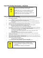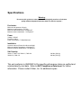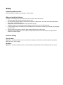
1
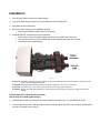
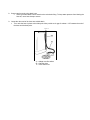
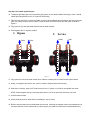
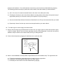
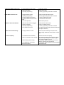
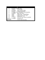
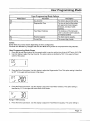
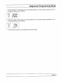
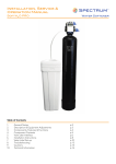
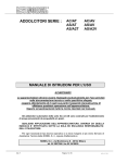
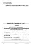
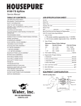
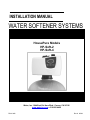
INSTALLATION MANUAL WATER SOFTENER SYSTEMS HousePure Models HP-Soft-2 HP-Soft-4 736-0137 Water, Inc. 1044 East Del Amo Blvd., Carson, CA 90746 www.waterinc.com ● 310-885-4400 P/N 41482 Rev A 06/04 Table of Contents IMPORTANT SAFETY INFORMATION – READ ALL ...................................................................................... 3 INSTRUCTIONS BEFORE USING ......................................................................................................................... 3 FEEDWATER ............................................................................................................................................................... 4 POWER ....................................................................................................................................................................... 4 INSTALLATION ........................................................................................................................................................... 4 SALT CAPACITY ......................................................................................................................................................... 4 SETUP.......................................................................................................................................................................... 5 UNPACKING AND INSPECTION .................................................................................................................................... 5 WHERE TO INSTALL THE SOFTENER ........................................................................................................................... 5 HARDNESS SETTING................................................................................................................................................... 5 INSTALLATION ........................................................................................................................................................ 6 CONTROL START-UP PROCEDURES ............................................................................................................... 10 SOFTENER OPERATION ...................................................................................................................................... 10 1. BRINE DRAW / SLOW RINSE POSITION ................................................................................................................. 10 2. BACKWASH POSITION .......................................................................................................................................... 10 3. FAST RINSE POSITION .......................................................................................................................................... 10 4. BRINE FILL ........................................................................................................................................................... 10 5. SERVICE ............................................................................................................................................................... 10 SERVICE................................................................................................................................................................... 11 CLEANING IRON OUT OF THE WATER SOFTENING SYSTEM ...................................................................................... 11 CHECKING FOR A SALT BRIDGE ............................................................................................................................... 11 BREAKING A SALT BRIDGE ...................................................................................................................................... 11 CLEANING THE INJECTORS AND SCREENS ................................................................................................................ 11 TROUBLESHOOTING ........................................................................................................................................... 12 WATER SOFTENER SYSTEM PARTS LIST...................................................................................................... 14 LIMITED WARRANTY ........................................................................... ERROR! BOOKMARK NOT DEFINED. Important Safety Information – Read All CAUTION: Read and follow the information in this manual to minimize the risk of electric shock or personal injury. ! IMPORTANT! If you are unsure about installing of your water softener, contact the helpline or consult a professional plumber. IMPORTANT! This system must be installed in compliance with applicable state and local codes, law, and regulations. Instructions Before Using Before beginning installation, read these all instructions completely. Then obtain all the materials and tools needed for installation. NOTE: Failure to install the HousePure Soft system correctly voids the warranty. Perform installation according to state and local plumbing codes. Use only lead-free solder and flux for sweat-solder connections, as required by state and federal codes. Handle all components of the system with care. Do not drop, drag or turn components upside down. Be sure the floor under the water softening system is clean and level. The system uses 120 volt-60Hz electrical power. Always use the power cord supplied. Plug power cord into an indoor 120 volt, grounded outlet. Properly ground system to conform to all codes and ordinances. Install system in a protected area. Be sure electric outlet and transformer do not come in contact with water. See Where to Install the Softener, in the installation section of the manual. Do not attempt to treat water over 110°F with the system. Always connect the system to the main water supply pipe before the water heater. Do not expose system to freezing temperatures. Water freezing in the system causes equipment damage. Do not install in direct sunlight. Heat from sun may cause damage. Minimum inlet water pressure is 20 psi. Maximum inlet water pressure is 125 psi. Use pressure reducing valve if necessary. Sodium used in the water softening process should be considered as part of your overall dietary salt intake. Contact physician if you are on a low sodium diet. Use clean water softening salts only, at least 99.5% pure. Failure to use the correct salt may create a health hazard or maintenance problems. Use nugget, pellet or coarse solar salts. Do not use rock, block, granulated or ice cream making salts. Always keep the salt lid in place unless servicing the unit or replenishing salt. CAUTION: ! Do not use with water that is unsafe or of unknown quality. Test water periodically to verify that the system is performing satisfactorily. Discard small parts remaining after the installation. Specifications Warning: Do not use this system on water that is microbiologically unsafe or of unknown quality without adequate disinfection before or after the system. ! Feed water: Minimum inlet pressure: 20 psig Maximum outlet pressure: 125 psig Minimum water temperature: 34 degrees F Maximum water temperature: 110 degrees F Power Voltage: 120VAC Frequency: 60Hz Power consumption: 7 Watts Maximum Installation Location: Indoors (Protect from direct sunlight) Minimum ambient temperature: 34 degrees F Maximum ambient temperature: 122 degrees F Salt Capacity 7000-1.0, 7000-1.25, 7000-1.5, 7000-2.0 7000-2.33, 7000-3.0 340 lbs (154 Kg) 600 lbs (272 Kg) This unit conforms to ANSI/NSF-44 for specific performance claims as verified and substantiated by test data. Refer to NSF Compliance Data Insert for further information. Please contact Water, Inc. for additional copies. Setup Unpacking and Inspection Check the system components for damage or missing parts. Where to Install the Softener Consider the following points when determining where to install the water softener: Place the system as close as possible to a sewer drain. Do not install the softener where it would block access to the water heater, or access to the main water shutoff, water meter, or electrical panels. Keep outside faucets on hard water to save soft water and salt. Install the softener in a place where water damage is least likely to occur if a leak develops. A 120V electrical outlet is needed to plug in the transformer. If the outlet is remote (up to 100 feet), use 18 gauge wire to connect. Always connect the system to the main water supply pipe before the water heater. Install the system where it will not be subject to temperatures outside of the limits stated in the Specification section or to direct sunlight. Hardness Setting Municipal Water: Water, Inc. recommends that you call your local water company to determine your water hardness in grains per gallon and iron in mg/l (or ppm). Well Water: Water, Inc. recommends that you have your water tested professionally for accurate hardness and iron content. Installation 1. Turn off gas or electric supply to the water heater. 2. Turn off the water supply to pipes to be cut and drain the house water pipes. 3. Open both hot and cold faucets. 4. Move the softener assembly into installation position. Be sure the installation surface is level and smooth. 5. Plumb IN and OUT connections to and from softener. Be sure the incoming hard water supply is directed to the INLET port of the valve. The valve body of the control is marked with arrows indicating the proper flow direction. Connections are illustrated below. Figure 1 CAUTION: If making a soldered copper installation, do all sweat soldering before connecting pipes to the bypass valve. Torch heat will damage plastic parts. CAUTION: When turning threaded pipe fittings onto plastic fittings, use care not to cross-thread. CAUTION: Use Teflon tape on all external pipe threads. Do not use pipe joint compound. CAUTION: Support inlet and outlet plumbing in some manner (use pipe hangers) to keep the weight off of the valve fittings. Perform steps 6-9 to install flexible drain hose. Skip to step 10 to install rigid drain pipe. 6. Find barbed hose fitting in small parts kit. Attach barbed hose fitting to the 1/2" male NPT drain outlet. 7. Cut the length of the hose in half. One section will be used as a valve drain hose. The remaining section will be used as an overflow hose in Step 11. 8. Connect and route the valve drain hose. Use the provided drain hose to attach to the valve drain fitting. To keep water pressure from blowing the hose off, use a hose clamp to secure. 9. Locate the other end of the hose at a suitable drain. Tie or wire the hose in place at the drain point. Also provide an air gap of at least 1-1/2" between the end of the hose and the drain point. Figure 2 A – Adapter overflow elbow B – Overflow hose C – Valve drain hose Use Step 10 to install rigid drain pipe. 10. To adapt a rigid drain pipe to the HousePure Soft system, do not attach barbed hose fitting to valve. Instead, plumb rigid tubing directly to the 1/2" male NPT drain fitting. 11. Take the other half of the cut hose and attach it to the overflow adapter elbow located on the side of the brine tank. Use a hose clamp to hold it in place. Locate the other end of the hose at the drain point as shown in Figure 2. 12. Fully open two (2) cold (soft) water faucets near the water softener. 13. Place bypass valve in "bypass" position 1. Bypass Outlet 2. Service Outlet Inlet Inlet Figure 3 14. Fully open the house main water shutoff valve. Observe a steady flow from both faucets opened earlier. 15. Slowly, turn bypass valve back in the “service” position. Keep soft water faucets open. 16. After about 3 minutes, open a HOT water faucet for one (1) minute, or until all air is expelled, then close. NOTE: If water appears cloudy or has salty taste, allow to run for several more minutes or until clear. 17. Close all water faucets. 18. Check plumbing work for leaks and fix immediately if any are found. 19. Remove the brine tank cover and add water into the tank. Although the material used in the manufacturing of this water softener will not contaminate your water supply, the softener could become contaminated during shipment and installation. The media inside the resin tank may also have become disturbed during shipping. The following procedure will help re-position the media, sanitize, flush and condition your water softener: a) Add 1-1/2 ounces of common household bleach to the water in the cabinet (brine tank). b) Following the directions in the Control Service Manual, manually advance the softener through each step of regeneration pausing for 10 minutes in each cycle except the Fill cycle (see step c.). c) See the enclosed Water Softener Performance Data Sheet for the Fill cycle time associated with your model. d) Repeat step 19a and 19c after any service has been performed on your water softener. 20. Turn ON the gas or electric supply to the water heater. 21. Remove the brine tank cover and add salt into the tank. Use only nugget, pellet or coarse solar salt with a purity of 99.5% or higher. DO NOT use rock, block, granulated, and ice cream-making salts, or salt with iron removing additives. Keep the cabinet cover closed unless servicing or refilling with salt. 22. Connect electrical power by plugging the transformer into a (120 volt) outlet. Figure 4 23. With the valve In Service, manually initiate a regeneration as the final installation step. This regeneration will: a) Fill the brine tank with the appropriate amount of water for the 1st regeneration b) Complete the final flushing and conditioning of the water softener. c) Re-classify the resin bed if the bed was disturbed during shipping. Control Start-up Procedures Control start-up, flushing/conditioning and programming procedures may be found in the control service manual included with your system. Model HP-Soft-2 HP-Soft-4 For replacement copies of this manual please contact Water, Inc. Softener Operation As water enters the softener, it passes over a resin bed in a special tank. The resin consists of tiny beads of a plastic called styrene. These beads attract and hold sodium ions and exchange the sodium for hardness ions when encountered. Over time, the resin becomes saturated with hardness ions and no longer removes hardness materials. The softener goes into a "regeneration" to flush hardness materials to the drain and refresh the resin with sodium. Regeneration is typically programmed to take place in the middle of the night when little or no water is in use. Regeneration consists of four cycles: 1. Brine Draw / Slow Rinse Position Brine Draw is the process in which brine is drawn out of the brine cabinet and passed through the resin in a downward direction. This rinses the resin and large amounts of sodium ions replace the hardness ions accumulated during service. Slow Rinse. After brine is completely removed from the brine cabinet into the resin tank the brine valve closes. Water replaces any remaining brine from the resin, flushing hardness ions removed from the resin to drain. 2. Backwash Position Backwash is a rapid upward flow of water that loosens the resin bed and flushes iron particles, dirt and sediments filtered in the bed out to the drain. 3. Fast Rinse Position Fast Rinse is a fast flow of water down through the resin tank that follows a Backwash. This flushes all remaining brine from the tank and packs the resin bed for softening efficiency. 4. Brine Fill Brine is water saturated with large amounts of a salt (sodium chloride). During brine fill, water flows into the salt storage area after each regeneration and dissolves salt. During the regeneration process, brine solution is drawn into the resin tank and hardness ions on the resin beads are exchanged for sodium ions. 5. Service When the softener is In Service, it is flowing water through the system and removing hardness minerals from your water. Service Cleaning Iron Out of the Water Softening System The HousePure Soft system is designed to remove minerals like calcium and magnesium from household water. Water, Inc. recommends periodic resin bed cleaning if your iron rating is high. Clean the bed at least every six months, or more if iron appears in the soft water between cleanings. Checking for a Salt Bridge A hard crust or "Salt Bridge" can form in the lower half of the salt storage tank. This can be deceiving because the tank will appear to have plenty of salt, but underneath, salt has hardened and when the system regenerates, water cannot quite reach this level to be made into brine (water and salt). Breaking a Salt Bridge Take a wooden broom handle and carefully push it down into the salt, working it up and down. If the tool strikes a hard object (be sure it's not the bottom or sides of the tank), it's probably a salt bridge. Carefully break the bridge with the broom handle. Do not pound on the walls of the tank. NOTE: Salt bridges are typically caused by high humidity or using the wrong kind of salt. In humid areas it is best to fill with less salt, more often. Use only nugget, pellet or coarse solar salt with a purity of 99.5% or higher. DO NOT use rock, block, granulated, and ice cream-making salts, or salt with iron-removing additives. Cleaning the Injector and Screen 1) Turn off water supply to conditioner: a) If the conditioner installation has a “three valve” by-pass system, first open the valve in the bypass line, and then close the valves at the conditioner inlet and outlet. b) If the conditioner has an integral by-pass valve, put it in the by-pass position. c) If there is only a shut-off valve near the conditioner inlet, close it. 2) Relieve water pressure in the conditioner by stepping the control into the backwash position momentarily. Return the control to the service position. 3) Unplug electrical cord from outlet. 4) Push down on the injector cap. Remove the injector cap clip. 5) To replace injector and screen. a) Pull the screen and injector throat/nozzle/check ball assembly out of the valve body. b) Insert a new injector throat/nozzle/check ball assembly; be sure they are sealed tightly. Install a new screen. c) Apply silicone lubricant to new injector cap seal. 6) Reinstall the injector cap and clip. 7) Return by-pass or inlet valving to normal service position. Water pressure should now be applied to the conditioner, and any by-pass line shut off. 8) Check for leaks at all seal areas. Check drain seal with the control in the backwash position. 9) Plug electrical cord into outlet. 10) Set time of day and cycle the control valve manually to assure proper function. Make sure control valve is returned to the service position. 11) Make sure there is enough salt in the brine tank. 12) Start regeneration cycle manually if water is hard. Troubleshooting 1. Softener Fails To Regenerate. A. Electrical service to unit has been interrupted. B. Timer programming bad (improper programming). A. Assure permanent electrical service (check fuse, plug, pull chain or switch). B. Check programming and reset as needed. 2. Softener Delivers Hard Water. A. By-pass valve is open. B. No salt in brine tank. A. Close by-pass valve. B. Add salt to brine tank and maintain salt level above water level. C. Clean or replace injectors and screen. D. Check brine tank fill time and clean brine line flow if plugged. E. Repeated flushings of the hot water tank is required. F. Check flow indicator light for flow. Remove obstruction from flow meter. G. Check meter cable connection to timer and meter. H. Reprogram the control to the proper regeneration type, inlet water hardness, and capacity or flow meter size. I. Remove and clean any sediment from brine tank and brine valve assembly. C. Injectors or screen plugged. D. Insufficient water flowing into brine tank. E. Hot water tank hardness. F. Flow meter jammed. G. Flow meter cable disconnected or not plugged into meter. H. Improper programming. I. Plugged brine line or air check. J. Salt bridge has formed. J. Refer to Breaking a Salt Bridge section in manual. K. No water in brine tank. K. Ensure safety float is not stuck. L. Unit is plumbed backwards. L. Check that the unit is plumbed correctly. M. Water hardness has increased or is M. Retest hardness and change settings set incorrectly. N. Water pressure is too low. N. Line pressure must be at least 20psi. 3. Unit Uses Too Much Salt. A. Improper salt setting. B. Excessive water in brine tank. C. Improper programming. A. Check salt usage and salt setting. B. See problem No. 7. C. Check programming and reset as needed. 4. Loss of Water Pressure. A. Iron buildup in line to water conditioner. B. Iron buildup in water conditioner. A. Clean line to water conditioner. 5. Loss of Resin Through Drain Line. A. Air in water system. B. Drain line flow control is too large. 6. Iron in Conditioned Water. A. Fouled resin bed. B. Clean control and add resin cleaner to resin bed. Increase frequency of regeneration. A. Assure that well system has proper air eliminator control and check for dry well condition. B. Ensure drain line flow control is sized correctly. A. Check backwash, brine draw and brine tank fill. Increase frequency of regeneration. Increase backwash time. B. Iron content exceeds recommended B. Add iron removal from filter or system. parameters. 7. Excessive Water in Brine Tank. A. Plugged drain line flow control. B. Brine valve failure. C. Improper programming. A. Clean flow control. B. Clean brine valve. C. Check programming and reset as needed. 8. Salt Water in Service Line. A. Plugged injector system. B. Improper programming. C. Foreign material in brine valve. D. Foreign material in brine line flow control. E. Low water pressure. A. Clean injector and replace screen. B. Check programming and reset as needed. C. Clean or replace brine valve. D. Clean brine line flow control. 9. Softener Fails to Draw Brine. A. Drain line flow control is plugged. B. Injector is plugged. C. Improper programming. D. Line pressure is too low. A. Clean drain line flow control. B. Clean or replace injectors. C. Check programming and reset as needed. D. Increase line pressure (line pressure must be at least 20psi at all times.) 10. Drain Flows Continuously. A. Foreign material in control. A. Remove piston assembly and inspect bore, remove foreign material & check control in various ports. 12. Loss of capacity. A. Increased raw water hardness A. Reset unit to the new capacity. B. Brine concentration and/or quantity. B. Keep brine tank full of salt at all times. Clean it yearly. Salt may be bridged. If using a salt grid plate ensure refill water is over it. C. Resin fouling. Future fouling. C. Call Pentair Water Treatment, find out how to confirm it, clean the resin and prevent. D. Poor distribution, channeling D. Call Pentair Water Treatment. Check distributors (uneven bed surface). and backwash flow. E. Raise water pressure. Water Softener System Parts List Figure 5 Item No. 2 3 4 5 6 7 11 12 13 14 Not Shown Not Shown-See Service Manual Part No. L1103027-02 15056-2 L1103009 60795-00 L1108001-02 L1108006 10329 10330 10332 L1108042 L1108009 Description Brine Tank 4" Brine Well Tank (10x54) w/ base Distributor Assembly Air Check/Brine Valve Assembly Brine Line Tube Fitting, Tube, .375 Nut, Brass Fitting, Sleeve, .375, Delrin Fitting, Insert, .375 Resin (See spec sheet for quantity) Installation Kit Control Valve Assembly