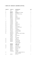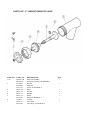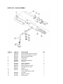
1
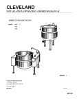
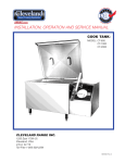
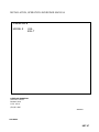
INSTALLATION, OPERATION AND REPAIR MANUAL
GAS KETTLE
MODEL #
KGL
KGL-T
CLEVELAND RANGE INC.
1333 East 179th St.
Cleveland, Ohio
U.S.A. 44110
(216)481-4900
222-01CO
9102 REV:0
KET-07
IMPORTANT
THE FOLLOWING POINTS ARE TO INSURE THE SAFE INSTALLATION AND
OPERATION OF THIS EQUIPMENT :
INSURE ALL GAS AND ELECTRICAL SUPPLIES MATCH RATING PLATE AND
ELECTRICAL STICKERS
OBSERVE ALL CLEARANCE REQUIREMENTS
DISCONNECT THE ELECTRICAL POWER SUPPLY TO THE APPLIANCE BEFORE
CLEANING OR SERVICING UNIT
ONLY A QUALIFIED SERVICE TECHNICIAN SHOULD REPAIR UNIT
THE INSTALLATION AND CONNECTION MUST COMPLY WITH LOCAL CODES, OR IN
THE ABSENCE OF LOCAL CODES, WITH CAN1 B149 INSTALLATION CODE OR WITH
THE NATIONAL FUEL GAS CODE, ANSI 2223.1-1988.
POST IN A PROMINENT LOCATION, INSTRUCTIONS TO BE FOLLOWED IN THE EVENT
THE USER SMELLS GAS. THIS INFORMATION SHALL BE OBTAINED BY CONSULTING
YOUR LOCAL GAS SUPPLER.
THE APPLIANCE AND ITS INDIVIDUAL SHUT OFF VALVE MUST BE DISCONNECTED
FROM THE GAS SUPPLY PIPING SYSTEM DURING ANY PRESSURE TESTING OF THAT
SYSTEM AT TEST PRESSURES IN EXCESS OF 1/2 PSIG. (3.45 KPA).
THE APPLIANCE MUST BE ISOLATED FROM THE GAS SUPPLY PIPING SYSTEM BY
CLOSING ITS INDIVIDUAL MANUAL SHUT OFF VALVE DURING ANY PRESSURE
TESTING OF THE GAS SUPPLY PIPING SYSTEM AT TEST PRESSURES EQUAL TO OR
LESS THAN 1/2 PSIG (3.45 KPA).
RETAIN THIS MANUAL FOR YOUR REFERENCE.
1
FOR YOUR SAFETY
Gas fired kettles are only to be installed under
a ventilation hood in a room which has
provisions for adequate make up air.
DO NOT STORE OR USE GASOLINE OR
OTHER FLAMMABLE LIQUIDS AND
VAPOURS IN THE VICINITY OF THIS OR
ANY OTHER APPLIANCE.
Electrical installation must be in accordance
with local codes and/or the National Electric
Code ANSI/NFPA 70-1987 (USA) or the
Canadian Electrical Code CSA Standard C22.1
(Canada). The kettle must be electrically
grounded by the installer. Standard supply
voltage is 115 volts A.C. However, optional
A.C. voltages can be supplied on special order.
A separate fused disconnect switch must be
supplied and installed in the high voltage
electrical supply line. The wire gauge size and
electric supply must match the power
requirements specified on the kettle's rating
plate. The conduit-enclosed permanent copper
wiring must be adequate to carry the required
current at the rated voltage. Refer to the
specification sheet for electrical specifications
and location of electrical connections.
- -IF YOU SMELL GAS - 1. OPEN WINDOWS
2. DO NOT TOUCH
ELECTRICAL SWITCHES.
3. EXTINGUISH ANY OPEN FLAME.
4. CALL YOUR GAS
SUPPLIER IMMEDIATELY.
GENERAL INSTALLATION INSTRUCTIONS
Installation of kettle must be accomplished
by qualified installation personnel, working to
all applicable local and national codes.
Improper installation of product could cause
injury or damage.
INSPECTION
Before unpacking visually inspect the unit for
evidence of damage during shipping. If
damage is noticed, do not unpack the unit,
follow shipping damage instructions.
This equipment is built to comply with
applicable standards for manufacturers.
Included among those approval agencies are:
UL, A.G.A, NSF. ASME/N.Bg, CSA, CGA, ETL,
and others. Many local codes exist, and it is
the responsibility of the owner and installer to
comply with these codes.
SHIPPING DAMAGE INSTRUCTIONS
If shipping damage to the unit is discovered or
suspected, observe the following guidelines in
preparing a shipping damage claim.
Observe all clearance requirements to provide
proper make-up air flow as well as sufficient
clearance for servicing. Dimensions and
clearance specifications are shown on the
specification sheet. Do not install kickplates or
otherwise obstruct the flow of combustion and
ventilation air. Check the rating plate to ensure
that the kettle has been equipped to operate
with the type of gas available at the installation.
1.
2.
2
Write down a description of the
damage or the reason for suspecting
damage as soon as it is discovered.
This will help in filling out the claim
forms later.
As soon as damage is discovered or
suspected, notify the carrier that
delivered the shipment.
3.
Arrange for the carrier's
representative to examine the
damage.
4.
Fill out all carrier claims forms and
have the examining carrier sign and
date each form.
pipe joint compound which is resistant to
L.P. gas. Test all pipe joints for leaks with
soap and water solution. Ensure that the gas
pressure regulator is set for the manifold
pressure indicated on the gas rating plate.
The appliance and its individual shut-off
valve must be disconnected from the gas
supply piping system during any pressure
testing of that system at test pressures in
excess of 1/2 psi (3.45 kPa). The appliance
must be isolated from the gas supply piping
system by closing its individual manual shutoff valve during any pressure testing of the
gas supply piping system at test pressures
equal to or less than 1/2 psi (3.45 kPa).
INSTALLATION
The first installation step is to refer to the
specification sheet for clearance
requirements, in order to determine the
location of the kettle. Next, carefully cut
open the shipping carton for easy removal
of the kettle.
ELECTRICITY
Position the kettle in its permanent location,
and level the kettle by tuning the adjustable
feet.
Remove the two screws securing the
console cover, and remove the cover. A
wiring diagram is affixed to the inside of the
cover. Feed conduit-enclosed permanent
copper wiring through the cutout in the
bottom of the console and fasten to the
terminal block. Fasten the ground wire to the
ground lug, connected to the frame, beside
the terminal block. Replace the console
cover and secure it with the screws.
Once positioned and leveled, permanently
secure the kettle's flanged feet to the floor
using 5/16 x 2 1/2 inch lag bolts and floor
anchors (supplied by the installer). Three
bolts per leg are required to secure each of
the flanged feet.
WATER
GAS
The sealed jacket of the gas-fired kettle is
precharged with the correct amount of a
water-based formula, and therefore, no
water connection is required to the kettle
jacket.
It is recommended that a sediment trap
(drip leg) be installed in the gas supply line.
If the gas pressure exceeds 14" water
column, a pressure regulator must be
installed, to provide a maximum of 14"
water column gas pressure to the gas
control valve.
Connect the gas supply piping to the input
side of the gas control valve. Location and
pressure data are shown on the
specification sheet. Installation must be in
accordance with local codes and/or the
National Fuel Gas Code ANSI Z223.1-1984
(USA) or Installation Codes for Gas
Burning Appliances and Equipment CANI
B149.1 and B149.2 (Canada). Use a gas
3
and the gas burners have been automatically
shut off by the kettle's safety circuit. Water must
be added to the reservoir before further use.
Refer to the "Reservoir Fill Procedures" for
details.
OPERATION
1.
Before turning the kettle on, read the
vacuum/pressure gauge. The gauge's
needle should be in the green zone. If
the needle is in the "vent air" zone, call
your service agent to locate and repair
the source of the leak. Under normal
circumstances the kettle should
operate for years without venting.
2.
Ensure that the electrical service to the
kettle is turned on.
3.
Place the kettle's power on/off switch to
the "ON" position.
6.
Turn the temperature control knob to
the required temperature setting. The
green light will cycle on and off with the
solid state control, indicating the
burners are cycling on and off to
maintain the set temperature.
8.
Pour the contents of the kettle into an
appropriate container by opening the
draw-off valve. Care should be taken to
pour slowly enough to avoid splashing
of the product.
CARE AND CLEANING
NOTE: When cooking egg and milk products,
the kettle should not be preheated, as products
of this nature adhere to hot cooking surfaces.
These types of food should be placed in the
kettle before heating is begun.
Place product into the kettle.
When cooking is completed, turn knob
to minimum and place the power on/off
switch to the "OFF" position.
NOTE: As with cleaning food soil from any
cookware, an important part of kettle cleaning is
to prevent foods from drying on. For this
reason, cleaning should be completed
immediately after cooked foods are removed.
Refer to the "Care and Cleaning Instructions"
for detailed kettle washing procedures.
4. Pre-heat the kettle by turning the
temperature control knob to the desired
temperature setting. The green light
will remain lit (indicating the gas
burners are ignited) until the
temperature setting is reached. When
the green light goes off, the burners
are off, and pre-heating is complete.
5.
7.
Your Cleveland kettle must be cleaned
regularly to maintain its fast, efficient cooking
performance, and to ensure its continued safe,
reliable operations.
NOTE: The red "low water" light should not be
lit during kettle operation. This light indicates
that the water level has reached a critically low
level,
4
1.
Prepare a warm water and mild
detergent solution in the kettle.
2.
Remove food deposits inside the kettle
using a nylon brush. Do not use a metal
bristle brush, as this may permanently
damage the kettle's stainless steel
surface.
3.
Loosen food which is stuck to the kettle
by allowing it to soak at a low
temperature setting.
4.
Open the draw-off valve to drain the
wash water.
5.
The draw-off valve should be
cleaned as follows:
a.
Remove the drain screen from
the bottom of the kettle.
Thoroughly wash and rinse
the screen, either in a sink or
dishwasher, then replace it
into the kettle.
b.
Disassemble the draw-off
valve, first by turning the valve
knob counter-clockwise, then
turning the large hex nut
counter-clockwise, until the
valve stem is free of the valve
body.
c.
In a sink, wash and rinse the
valve stem, hex nut, and
knob. Wash and rinse the
inside of the valve body using
a nylon brush.
d.
Do not allow water to run into
electrical controls. Always turn off
equipment power before using water
to wash equipment.
DO NOT HOSE DOWN THE KETTLE.
NOTE: For more difficult cleaning
applications, one of the following can be
used: alcohol, baking soda, vinegar, or a
solution of ammonia in water. Avoid the use
of chloride cleansers, which may damage
the kettle's stainless steel surface.
WARNING: Steel wool should never be
used for cleaning the kettle. Particles of the
steel wool become embedded in the
surface and rust. This will weaken and
corrode the stainless steel surface.
MAINTENANCE
Cleveland kettles require very little
preventive maintenance, other than daily
cleaning.
Reassemble the draw-off valve
by reversing the procedure for
disassembly. The valve's hex
nut should be hand tight only.
6.
Rinse the kettle interior thoroughly,
then drain the rinse water.
7.
Leave the cover and draw-off valve
open when the kettle is not in use.
8.
Exterior Care: Allow kettle to cool
before washing. Use the same
cleaners and cleaning procedures as
for other kitchen surfaces of
stainless steel and aluminum. Mild
soapy water, with a clear water rinse,
is recommended.
DRAW-OFF VALVE MAINTENANCE
To correct a leak at the draw-off valve, the
source of the leak must first be determined.
Leaks from around the valve stem are
corrected by simply replacing the "O"ring.
Faulty seating of the valve stem disc
against the valve body seat may cause
dripping from the valve even when the
valve is tightly closed. This can often be
corrected by cleaning any residue from the
disc and seat.
Our Company supports a worldwide network
of Maintenance and Repair Centres. Contact your
nearest Maintenance and Repair Centre for
replacement parts, service, or information
regarding the proper maintenance and
repair of your cooking equipment.
5
In order to preserve the various agency safety
certification (UL, A.G.A., CSA. CGA, NSF,
ASME/Ntl. Bd., etc.), only factory-supplied
replacement parts should be used. The use of
other than factory-supplied replacement parts
will void the warranty.
gauge shows at least 5 psi pressure. Any
bubbles which appear will indicate a leak.
RESERVOIR FILL PROCEDURES
The reservoir's water level must be maintained
at the proper level. Under normal operating
conditions, the sealed water reservoir should
not require the addition of water. If the red "low
water" light comes on during use, the water
level has reached a critically low level. The low
water protection control has automatically shut
off the gas burners. The following procedure
must be completed before further use:
KETTLE VENTING INSTRUCTIONS
If the vacuum/pressure gauge reading is in the
"vent air" zone, it means that air has entered
the steam/water jacket, resulting in little or no
vacuum. This reduces kettle efficiency by
slowing its heating process. To remedy this
situation, the following venting procedures
should be followed:
1.
WARNING: Insure there is no pressure IN the
unit before removing filler cap.
With the temperature control knob set
at number 9, heat the empty kettle until
the vacuum/pressure gauge indicates
5-10 psi.
2. Release steam and air from the
steam/water jacket by pulling out on
the pin of the safety valve for
approximately 10-15 seconds.
The kettle's steam and air from the
steam/water jacket should now be free of air.
At room temperature, the pressure gauge
needle should rest in the green zone,
indicating a vacuum in the kettle's jacket. To
check the gauge for proper vacuum after
venting, the temperature can be quickly
reduced by filling the kettle with cold water.
1.
Shut off power to the kettle.
2.
Remove water fill cap located at the
rear of the kettle.
3.
Add distilled water until the water level
is between the "HI" and "LO'' markings
on the sight gauge glass.
4.
Replace the water fill cup and carefully
tighten. Do not over-tighten.
5.
Restore power to the kettle.
6.
The kettle must now be vented. Refer
to the "Kettle Venting Instructions".
CAUTION: It is recommended that only
distilled water be used when adding water to a
partially filled water reservoir. Local tap water
conditions may cause kettle damage which is
not covered under warranty. Add water until
the level is between the "HI" and "LO" marks
on the sight gauge.
If the kettle will not hold vacuum, have a
qualified service technician test for leaks at the
water fill plug, sight gauge, safely valve, probe,
and vacuum/pressure gauge fittings. We
suggest mixing a 50/50 solution of liquid
detergent and water while heating the kettle to
at least 5 psi pressure. Then, shut off power to
the kettle. The soapy solution should be
applied to the suspected area while the
6
PARTS LIST - ELECTRICAL COMPONENT BOX ASSEMBLY
ITEM NO.
1.
2.
3.
4.
5.
6.
7.
8.
9.
10.
11.
PART NO.
KE51141
KE52690
KE53469
KE00458
KE50753
KE53316
FI 05050
KE53436
KE51164
KE52281
KE51139
DESCRIPTION
Transformer, 120-16V.
Bushing
Ignition module
Solid state control
Relay
Safety thermostat
Brass nut # 7/16-24
Air switch
Transformer 120-24V.
Fuse bussman MDL-1/2 amp
Fuse holder
QTY.
1
1
1
1
1
1
1
1
1
1
1
PARTS LIST - PRESSURE RELIEF ASSEMBLY
ITEM-NO.
1.
2.
3.
4.
5.
6.
7.
8.
9.
10.
11.
12.
13.
PART NO.
FI05215
FI05225
FI00151
KE51014
FI00596
FI05214
RT00370
KE51723
FI00598
FI052l6
FI05224
FI05221
FI05050
DESCRIPTION
Cap, 1/2"
Nipple, 1/2"
Street elbow, 1/2"
Check valve
Nipple
Cross tee
Tubing, 1/4" copper(per ft.)
Safety valve, 50 p.s.i
Nipple
Elbow, FIP x FIP
Nipple
Reducer, 1/2" pipe to 1/4" tube
Compression nut, 1/4"
QTY.
1
1
2
1
1
1
3
1
1
1
1
1
1
PARTS LIST - GAS CONTROL ASSEMBLY ( KETTLE )
ITEM NO.
1.
2.
3.
4.
5.
6.
7.
8.
9.
10.
11.
12.
13.
14.
15.
16.
17.
18.
19.
20.
PART NO.
KE53402
KE53402-1
KE01426
KE53387
KE53515
KE535151
F01518
KE53441
KE53422
KE53403
KE53403-1
KE53403-2
KE53403-3
FA00114
FI00073
DESCRIPTION
Air orifice, 140K BTU burner
Air orifice, 170K BTU burner
Mixing chamber
Swivel
Pipe
Gas control valve, N.G.
Gas control valve, L.P.
Shut-off valve
Reducer
Pipe
Pipe
Blower
Elbow
Pipe
Elbow
Plug
"O" Ring
Spring
Orifice, .227, N.G., 140K BTU, 2000 ft.
Orifice, .228, L.P., 140K BTU, 2000 ft.
Orifice, .303, N.G., 170K BTU, 2000 ft.
Orifice, .246, L.P., 170K BTU, 2000 ft.
"O" Ring
Pipe
Union
QTY.
1
1
1
1
1
1
1
1
1
1
1
1
1
1
1
1
1
1
1
1
GAS CONTROL ASSEMBLY ( KETTLE )
PARTS LIST - SIDE BOX ASSEMBLY (KETTLE)
ITEM NO.
1.
2.
3.
4.
5.
6.
7.
8.
9.
10.
11.
12.
13.
14.
15.
1617.
18.
19.
20.
21.
22.
23.
24.
25.
26.
27.
28.
29.
30.
31.
PART NO.
N/A
KE53437
KE01432
KE00515
KE517111
KE52833
KE50315
KE50245
KE51738
FA10623
FA20029
FA950551
FA95008
FA30088
FA95050
KE52191
KE52192
KE52193
KE51891
KE517112
KE51730
FA19186
KE503752
KE50569-1
KE50569
SE00074
KE51005
FA32027
KE50567
KE00508
KE50429
SK50055
KE50504
SK50062
KE50568
KE50473
KE50556
KE50955-1
KE52871
KE51053
FA05002-30
32
33.
FI00196
DESCRIPTION
Sight glass
Igniter
Enclosure cover assembly
Thermistor
R.H. Trunnion bearing
Gear
Worm
Bearing
Sleeve, bearing
Bolt, hex bead
Nut
Key
Locknut
Washer
Retaining ring
Bearing
Thrust washer
Thrust washer spacer
Washer
L.H. Bearing
Tilt shaft bearing
Screw, hex socket
Tilt shaft
Temperature Control Assembly
Knob
Potentiometer
Seal
Star Washer
L.E.D., red
Hand wheel
Pressure gauge
Terminal block
Switch Assembly
Toggle switch
Rubber Boot
L.E.D., green
Ground lug
Water level probe
Retaining cover
Washer
Sight glass
"O"-Ring
Electrical Component Box Assy.
(See Pg. 222-09TD)
Drain cap
QTY.
1
1
1
1
1
1
1
1
1
1
1
1
2
1
1
2
4
3
1
1
1
1
1
1
1
1
1
1
1
1
1
1
1
1
1
1
1
1
1
1
1
SIDE BOX ASSEMBLY ( KETTLE )
PARTS LIST - 2" TANGENT DRAW-OFF VALVE
ITEM NO. PART NO.
1. to 7.
KE50972-B
KE509721
1.
FA21008
FA95049
FA11134
2.
KE527551
3.
KE52754
4.
KE52753
5.
KE52752
KE53290
6.
FA00111
7.
KE52751
KE53289
DESCRIPTION
Draw-off assembly
Draw-off assembly, for KDM-40-T
Hex nut
Wing nut
Screw, for KDM-40-T
Knob
Hex nut
Retainer
Piston
Piston, for KDM-40-T
''O"Ring
Valve body
Valve body, for KDM-40-T
QTY.
1
1
1
1
1
1
1
1
PARTS LIST - HINGE ASSEMBLY
ITEM NO.
1. - 9.
1.
2.
3.
4.
5.
6.
7.
8.
9.
10.
11.
12.
13.
14.
PART NO.
KE00598
SK00168
KE51218
KE50824
KE50823
KE50820
KE50819
FA11507
FA11284
KE50122
KE50121
KE50821
KE50151
KE00095
FA30500
FA11223
DESCRIPTION
Hinge assembly (40 gal. and under)
Hinge assembly (60 gal. and over)
Body, spring assist hinge
Hinge bearing
Pin (hinge)
Insert, brass adjustment
End piece
Screws, adjustment
Bolts, end block
Spring (40 gal. and under)
Spring (60 gal. and over)
Cylinder
Knob, ball type
Cover handle (specify model)
Lid holder
Washer, lid holder
Bolt, lid holder
QTY.
1
1
1
1
1
1
1
2
2
1
1
1
1
1
1
1
1