1
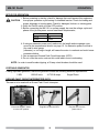
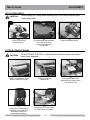
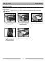
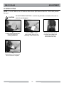
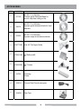
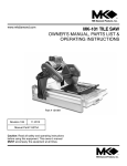
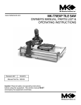
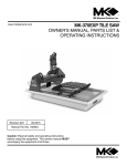
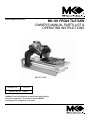
www.mkdiamond.com
MK-101 Pro24 Tile Saw
OWNER’S MANUAL PARTS LIST &
OPERATING INSTRUCTIONS
MK-101 Pro24
Revision 303
02.2015
Manual Part No. 158808
Caution: Read all safety and operating instructions before
using this equipment. This owners manual MUST
accompany the equipment at all times.
INTRODUCTION
Congratulations on your purchase of a MK-101 Pro24 Tile Saw. We are certain that you will be
pleased with your purchase. MK Diamond takes pride in producing the finest construction power
tools and diamond blades in the industry.
Operated correctly, your MK-101 Pro24 should provide you with years of service. In order to help
you, we have included this manual. This owners manual contains information necessary to operate
and maintain your MK-101 Pro24 Tile Saw safely and correctly. Please take a few minutes to
familiarize yourself with the saw by reading and reviewing this manual.
If you should have questions concerning your saw, please feel free to call our friendly customer
service department at: 800 421-5830
Regards,
MK Diamond
NOTE THIS INFORMATION FOR FUTURE USE:
MODEL NUMBER:
SERIAL NUMBER:
PURCHASE PLACE:
PURCHASE DATE:
NOTE: For your (1) one year warranty to be effective, complete the warranty
card (including the Serial Number) and mail it in as soon as possible.
2
TABLE OF CONTENTS
Page
SAFETY
Safety Messages
4
Damage Prevention Message
4
General Safety Precautions
4-7
California Proposition 65 Message
8
Canadian French Safety Translation
9-14
Electrical Requirements
15-18
Safety Label Locations
19
Lockout
20
Product Specifications
20
ASSEMBLY
Unpacking
Contents
Transport
Stand
Assembly
21
21
22
22
23-25
SETUP, ADJUSTMENT AND OPERATION
Setup
26-27
Operation28
Adjustment
29-34
Cleanup
35
MAINTENANCE AND TROUBLESHOOTING
Maintenance
Troubleshooting
36-41
42-47
EXPLODED VIEW AND PARTS LIST
Exploded View & Parts List
48-57
ACCESSORIES
Accessories
58
ORDERING and RETURN INSTRUCTIONS
Ordering Information
Return Material Policy
Packaging Instructions
Authorized Service Centers
Warranty
60
60
60
61
61
3
MK-101 Pro24
SAFETY
Read and follow all safety, operating and maintenance instructions. Failure to read and follow
these instructions could result in injury or death to you or others. Failure to read and follow these
instructions could also result in damage and/or reduced equipment life. Safety warnings and
guidelines do not by themselves eliminate danger. They are not substitutes for proper accident
prevention procedures and good judgement.
))
SAFETY MESSAGES
ON
)
)
A safety message alerts you to potential hazards that could hurt you or others. Each safety message is
preceded by a safety alert symbol (
) and one of three words: DANGER, WARNING, or CAUTION.
((
((
ON
))
ON
((
DANGER
You WILL be KILLED or SERIOUSLY INJURED if you do not follow directions.
))
ON
((
WARNING You CAN be KILLED or SERIOUSLY INJURED if you do not follow directions.
CAUTION
You CAN be INJURED if you do not follow directions. It may also be used to
alert against unsafe practices.
DAMAGE PREVENTION AND INFORMATION MESSAGES
A Damage Prevention Message is to inform the user of important information and/or instructions that
could lead to equipment or other property damage if not followed. Information Messages convey
information that pertains to the equipment being used. Each message will be preceded by the word
NOTE, as in the example below.
NOTE: Equipment and/or property damage may result if these instructions are not followed.
general safety precautions and hazard symbols
In order to prevent injury, the following safety precautions and symbols should be followed at all times!
ALWAYS read this Owner’s Manual before operating the machine. DO NOT operate or
service this equipment before reading this entire manual. Read and understand all warnings, instructions and controls on the machine. Know how to stop the equipment quickly in
case of emergency. It is the operators responsibility to use this machine under safe working conditions and conform with federal, state and local codes or regulations pertaining to
safety, air, pollution, noise etc...
ALWAYS keep the Blade and Belt Guards in place. Do Not operate this machine with any
guard or safety device removed. A Guard, or any damaged part should be repaired or
replaced immediately.
NEVER operate this equipment without proper protective clothing, shatterproof glasses, steel-toed boots and other protective devices required by the job. Non-slip
foot wear is recommended.
))
((
ON
4
MK-101 Pro24 SAFETY
PERSONAL PROTECTIVE EQUIPMENT
always wear approved respiratory, head, ear and eye protection
when operating this machine.
ACCIDENTAL
STARTS!
))
Before starting the engine/motor, be sure the ON/OFF switch is in the OFF position to prevent accidental starting. Place the ON/OFF switch in the OFF position before performing any
service operation. ALWAYS place the power ON/OFF switch in the OFF position when the
machine is not in use.
ON
ON
))
((
((
((
))
ROTATING PARTS
Keep hands, feet, hair, and clothing away from all moving parts to prevent injury. Never operate the motor with covers, shrouds, or guards, removed.
HOT PARTS!
Engine components can become extremely hot from operation. To prevent severe burns,
do not touch these areas while the engine is running, or immediately after it is turned off.
Never operate the engine with heat shields removed.
))
((
ON
OVER SPEED
NEVER tamper with the governor components or settings to increase the maximum speed.
Severe personal injury and damage to the engine or equipment can result if operated at
speeds above maximum.
ELECTRICAL SHOCK
NEVER touch electrical wires or components while the engine is running. Exposed, frayed or
worn electrical wiring and plugs can be sources of electrical shock which could cause severe
injury or burns. Do not touch the plug with wet hands.
))
((
ALWAYS avoid inhalation of and skin contact with silica dust and/or mist. Provide proper
dust removal. Use dust-collection system when applicable.
NEVER operate the machine in an explosive atmosphere or near combustible materials.
))
Sparks
from the cutting-action of this machine can ignite flammable materials, liquids, gases
or dust.
((
ON
))
ON
((
This equipment should not be operated by persons under 18 years of age.
KEEP CHILDREN AWAY
)
All) visitors and children should be kept a safe distance from work area. Maintain a safe
operating distance to other personnel.
((
ON
MAKE
THE WORKSHOP KID PROOF
))
Make the workshops kid proof by using padlocks, master switches or by removing starter keys.
((
ON
DO NOT FORCE THE TOOL
A power tool will do a job better and safer operating at the rate for which it was designed.
DO NOT force a tool or an attachment to do a job that it was not designed to do.
5
MK-101)) Pro24 ON
((
SAFETY
((
ON
USE PROPER APPAREL
DO NOT wear loose clothing, gloves, neckties, rings, bracelets, or other jewelry that may
be ))caught in moving parts. Non-slip footwear is recommended. Wear protective hair covering to contain long hair.
SECURE WORK
Clamps
or a vise should be used to hold work whenever practical. Keeping your hands free
))
to operate a power tool is safer.
((
ON
DO)) NOT OVERREACH
Keep proper footing and balance at all times by not overreaching.
((
ON
((
ON
DISCONNECT TOOLS
Power
tools should always be disconnected before servicing, adjusting or when changing
))
accessories, such as blades, bits, cutters, and the like.
((
ON
MAINTAIN TOOLS WITH CARE
Keep tools clean and maintained for the best and safest performance. Always follow
maintenance instructions and examine the machine before use. If any abnormal vibrations
))
or noises
occurs, turn off machine immediately and have the problem corrected before
further use.
REMOVE ADJUSTING KEYS AND WRENCHES
)) a habit of checking to see that keys and adjusting wrenches are removed from
Form
the power tool before it is turned on.
((
ON
KEEP WORK AREA CLEAN
Cluttered
work areas and benches invite accidents. Keep area around machine clear of
))
obstructions which could cause persons to fall.
((
ON
((
ON
DO NOT USE IN DANGEROUS PLACES
DO NOT operate equipment in dangerous or hazardous environments. DO NOT use power
tools
)) in damp or wet locations nor expose them to rain. Always keep the work area well
lighted.
((
ON
USE RECOMMENDED ACCESSORIES
Consult the owner’s manual for recommended accessories. Using improper accessories
may
increase the risk of personal or by-stander injury. Unauthorized equipment
))
modifications will void all warranties. Manufacturer does not assume responsibility for any
accident due to equipment modifications.
))
ON
((
Always ensure that the machine is on level ground before using.
NEVER STAND ON THE TOOL
))
Serious
injury could occur if a power tool is tipped, or if a cutting tool is unintentionally
contacted.
((
ON
TRANSPORT
When loading or unloading the machine, use caution. Remove the blade prior to hoisting,
loading and transporting the machine.
6
MK-101)) Pro24 ON
((
SAFETY
((
ON
CHECK FOR DAMAGED PARTS
Before using a power tool, check for damaged parts. A guard or any other part that is
damaged should be carefully checked to determine if it would operate properly and
perform its intended function. Always check moving parts for proper alignment or binding.
Check for broken parts and mountings and all other conditions that may affect the
))
operation
of the power tool. A guard, or any damaged part, should be properly repaired or
replaced. Always check the machine for loose bolts before starting.
((
ON
DIRECTION OF ROTATION
A blade or cutter should always be installed so that rotation is in the direction of the
arrow
imprinted on the side of the blade or cutter. It should correspond with the rotational
))
direction of the motor. Always feed work into a blade against the direction of rotation.
((
ON
NEVER LEAVE A TOOL UNATTENDED
TURN
POWER OFF - Do not leave a tool until it comes to a complete stop. Always
))
turn a power tool OFF when leaving the work area, or, when a cut is finished.
((
ON
NEVER disconnect any "emergency or safety devices". These devices are intended for operator safety. Disconnection of these devices can cause severe injury, bodily harm, or
even death! Disconnection of any of these devices will void all warranties. Unauthorized
equipment
modifications will void all warranties. Manufacturer does not assume
))
responsibility for any accident due to equipment modifications.
))
ON
((
NEVER use this machine with any cutter designed for woodworking.
))
ON
((
NEVER operate this equipment when not feeling well due to fatigue, illness or taking medicine.
))
NEVER operate this equipment under the influence of drugs or alcohol.
((
ON
On belt driven equipment, overtensioning of belts will result in premature crank and/or bearing
failure.
))
((
ON
Whenever necessary, replace nameplate, operation and safety decals when they become
difficult
to read.
))
((
ON
Always store equipment properly when it is not being used. Equipment should be stored in
))
a clean, dry location out of the reach of children
((
ON
Do not lend or rent this equipment without including the Owner's Manual and the Engine/
))
Motor
Manufacturer's Manual.
((
ON
Check the chemical properties of the material to be cut/grinded and follow all EPA/OSHA
Regulations.
7
MK-101 Pro24 SAFETY
SILICA DUST WARNING
Grinding/cutting/drilling of masonry, concrete, metal and other materials with silica in their composition
may give off dust or mists containing crystalline silica. Silica is a basic component of sand, quartz,
brick clay, granite and numerous other minerals and rocks. Repeated and/or substantial inhalation of
airborne crystalline silica can cause serious or fatal respiratory diseases, including silicosis. In addition, California and some other authorities have listed respirable crystalline silica as a substance
known to cause cancer. When cutting such materials, always follow respiratory precautions.
Use appropriate NIOSH-approved respiratory protection where dust hazard may occur. Paper masks
or surgical masks without a NIOSH approval number are not recommended because they do little to
protect the worker. For more information about respirator programs, including what respirators have
received NIOSH approval as safe and effective, please visit the NIOSH website at:
http://www.cdc.gov/niosh/topics/respirators
Observe OSHA regulations for respirator use (29 C.F.R.§1910.134).
Visit http://www.osha.gov for more information.
CALIFORNIA PROPOSITION 65 MESSAGE
Some dust created by power sanding, sawing, grinding, drilling, and other construction activities contain chemicals known (to the State of California) to cause cancer, birth defects or other reproductive
harm. Some examples of these chemicals are:
• Lead, from lead-based paints
• Crystalline silica from bricks, cement and other masonry products
• Arsenic and chromium, from chemically treated lumber
For further information, consult the following sources:
http://www.osha.gov/dsg/topics/silicacrystalline/index.html
http://www.cdc.gov/niosh/docs/96-112/
http://oehha.ca.gov/prop65/law/P65law72003.html
http://www.dir.ca.gov/Title8/sub4.html
Your risk from these exposures varies depending on how often you do this type of work. To reduce
your exposure to these chemicals, work in a well-ventilated area, and work with approved safety
equipment, such as dust masks that are specially designed to filter out microscopic particles. Where
((
ON
))
use of a dust extraction
device is possible, it should be used. To achieve a high level of dust collection, use an industrial
HEPA vacuum cleaner. Observe OSHA 29 CFR part 1926.57 and 1926.103.
WARNING
Sawing, grinding and drilling generate dust. Excessive airborne particles may cause irritation to eyes, skin and respiratory
tract. To avoid breathing impairment, always employ dust controls and protection suitable to the material being sawed or
drilled; See OSHA (29 CFR Part 1910.1200).
8
MK-101 Pro24
DE SéCURITé
Lisez et suivez toutes les consignes de sécurité, d'utilisation et d'entretien. Ne pas lire et suivre ces
consignes pourrait entraîner des blessures, voire la mort, pour vous ou d'autres personnes. Ne pas lire
et suivre ces consignes pourrait aussi endommager et/ou raccourcir la durée de vie de l'équipement.
Les avertissements et les directives de sécurité n'éliminent pas, par eux-mêmes, les risques. Ils ne
remplacent pas les mesures efficaces de prévention des accidents et le bon jugement.
MESSAGES DE SÉCURITÉ
))
Un message
de sécurité vous signale les dangers potentiels pour vous ou d'autres personnes.
ON
))
Chaque message de sécurité est précédé par un symbole d'alerte de sécurité (
) et par l'un des
trois mots suivants : DANGER, AVERTISSEMENT ou ATTENTION.
((
((
ON
))
ON
((
DANGER
))
ON
LE NON-RESPECT des consignes entraînera des BLESSURES GRAVES voire
la MORT.
((
LE NON-RESPECT des consignes PEUT ENTRAÎNER des BLESSURES
AVERTISSEMENT GRAVES voire la MORT.
ATTENTION LE NON-RESPECT des consignes PEUT ENTRAÎNER des BLESSURES. Il
peut également être utilisé pour alerter contre les pratiques dangereuses.
PREVENTION DES DOMMAGES ET MESSAGES D'INFORMATION
Un message de prévention des dommages doit informer l'utilisateur des informations et/ou consignes
importantes, qui, si elles ne sont pas suivies, pourraient endommager l'équipement ou conduire à d'autres
dommages matériels. Les messages d'information transmettent des informations relatives à l'équipement
utilisé. Chaque message sera précédé par le mot REMARQUE, comme dans l'exemple ci-dessous.
REMARQUE : Des dommages à l'équipement et/ou des dommages matériels peuvent survenir si
les instructions ne sont pas suivies.
CONSIGNES DE SÉCURITÉ GÉNÉRALES ET SYMBOLES DE DANGER
Afin de prévenir les blessures, les consignes et les symboles de sécurité suivants doivent être respectés
en tout temps!
TOUJOURS lire ce manuel avant d'utiliser l'outil. NE PAS utiliser ou entretenir
cet équipement avant d'avoir lu ce manuel en entier. Lire et comprendre tous les
avertissements, instructions et commandes de l'outil. Savoir comment arrêter rapidement
l'équipement en cas d'urgence. Il est de la responsabilité de l'opérateur d'utiliser cet outil
dans des conditions de travail sûres et conformes aux codes et règlements fédéraux,
provinciaux et locaux relatifs à la sécurité, l'air, la pollution, le bruit, etc.
TOUJOURS garder les protections de la lame et de la courroie en place. NE PAS utiliser
cet outil en l'absence d'un dispositif de protection ou de sécurité. Une protection ou toute
pièce endommagée doit être réparée ou remplacée immédiatement.
NE JAMAIS utiliser cet équipement sans vêtements de protection appropriés,
lunettes incassables, bottes à embout d'acier et autres dispositifs de protection
requis par la tâche. Il est conseillé d'utiliser des chaussures antidérapantes.
))
((
ON
9
MK-101 Pro24
DE SéCURITé
ÉQUIPEMENT DE PROTECTION INDIVIDUELLE
Portez TOUJOURS l'équipement de protection respiratoire,
auriculaire et oculaire homologué lors de l'utilisation de cet outil.
ON
DÉMARRAGES
ACCIDENTELS!
))
))
Avant de démarrer le moteur, vérifiez que le commutateur MARCHE-ARRÊT est en position
ARRÊT (OFF) pour empêcher tout démarrage accidentel. Placez le commutateur MARCHEARRÊT en position ARRÊT (OFF) avant toute intervention d'entretien. Placez TOUJOURS le
commutateur MARCHE-ARRÊT en position ARRÊT (OFF) lorsque vous n'utilisez pas l'outil.
((
((
ON
((
))
N
))
((
ON
PIÈCES TOURNANTES
Éloigner les mains, les pieds, les cheveux et les vêtements des pièces mobiles pour éviter
des blessures. Ne jamais utiliser le moteur si le couvercle, l'enveloppe de protection ou les
protecteurs ont été retirés.
PIÈCES CHAUDES!
Les composants du moteur peuvent devenir très chauds pendant le fonctionnement. Pour éviter
des brûlures graves, ne pas toucher ces zones pendant que le moteur tourne ou immédiatement
après l’avoir arrêté. Ne jamais faire fonctionner le moteur sans les écrans de chaleur.
))
((
ON
SURVITESSE
NE JAMAIS modifier les composants ou réglages du limiteur de régime afin d’augmenter
la vitesse maximale. De graves blessures et des dommages au moteur ou à l’équipement
peuvent en résulter s’il fonctionne à des vitesses supérieures au maximum.
DÉCHARGE ÉLECTRIQUE
NE JAMAIS toucher les fils ou les composants électriques pendant que le moteur est en
marche. Les câbles et fiches nus, effilochés ou usés peuvent être des sources de choc
électrique qui pourraient provoquer de graves blessures ou brûlures. Ne pas toucher
la fiche avec des mains humides.
))
))
TOUJOURS éviter l'inhalation et le contact de la peau avec la poussière et/ou un nuage de
silice. Prévoir un système de dépoussiérage adéquat. Utiliser un système de captage des
poussières, le cas échéant.
((
NE JAMAIS utiliser l'outil dans une atmosphère explosive ou près de matériaux combustibles.
)
Les) étincelles produites par l'action de coupe de cet outil peuvent enflammer les matériaux,
les liquides, les gaz ou les poussières inflammables.
((
ON
))
ON
((
Cet équipement ne doit pas être utilisé par des personnes de moins de 18 ans.
GARDER LES ENFANTS À L’ÉCART
))
Tous
les visiteurs et les enfants doivent se tenir à bonne distance de la zone de travail.
Maintenir une distance d'utilisation sécuritaire par rapport aux autres membres du personnel.
((
ON
ON
RENDRE L'ATELIER SÛR POUR LES ENFANTS
Rentre
les ateliers sûrs pour les enfants à l'aide de cadenas, d'interrupteurs principaux ou
))
en retirant les clés de démarrage.
((
N
NE PAS FORCER L'OUTIL
Un outil électrique exécutera la tâche mieux et de manière plus sûre s’il est utilisé dans les
limites prévues. NE PAS forcer un outil ou un accessoire à exécuter une tâche pour laquelle
il n’est pas conçu.
10
))
MK-101 Pro24
DE SéCURITé
((
ON
((
ON
UTILISER DES VÊTEMENTS APPROPRIÉS
NE PAS porter de vêtements amples, gants, cravates, bagues, bracelets ou autres bijoux
susceptibles
de se prendre dans les pièces mobiles. Le port de chaussures antidérapantes
))
est recommandé. Les cheveux longs doivent être ramassés sous un couvre-chef.
FIXER LES PIÈCES DE TRAVAIL
Dans
la mesure du possible, utiliser des serre-joints ou un étau pour maintenir la pièce de
))
travail. Il est plus sûr de garder les mains libres pour manœuvrer un outil électrique.
((
ON
NE)) PAS TRAVAILLER HORS DE PORTÉE
Toujours se tenir bien campé et avoir un bon équilibre en ne travaillant pas hors de portée.
((
ON
((
ON
DÉBRANCHER LES OUTILS
Les) outils électriques doivent toujours être débranchés avant l'entretien, le réglage ou le
)
remplacement des accessoires, tels que lames, fraises et autres.
((
ON
ENTRETENIR SOIGNEUSEMENT LES OUTILS
Garder les outils propres et bien entretenus pour une performance optimale et sécuritaire.
Toujours suivre les instructions d'entretien et examiner l'outil avant utilisation. Si des
))
vibrations
ou des bruits anormaux se produisent, éteindre immédiatement l'outil et faire
corriger le problème avant toute nouvelle utilisation.
RETIRER LES CLÉS ET OUTILS DE RÉGLAGE
Prendre
l'habitude de vérifier que tous les outils et les clés de réglage ont été retirés
))
de l'outil électrique avant de le mettre en marche.
((
ON
GARDER LE LIEU DE TRAVAIL PROPRE
Un ))lieu de travail ou un établi encombré est propice aux accidents. Garder la zone autour
de la machine dégagée de tout obstacle qui pourrait faire tomber quelqu'un.
((
ON
((
ON
NE PAS UTILISER DANS DES ENDROITS DANGEREUX
NE PAS utiliser l'équipement dans des environnements dangereux. NE PAS utiliser les
outils
)) électriques dans des endroits mouillés ou humides, ne pas les exposer à la pluie.
Toujours garder le lieu de travail bien éclairé.
((
ON
UTILISER LES ACCESSOIRES RECOMMANDÉS
Voir les accessoires recommandés dans le manuel d'utilisation. L'utilisation d'accessoires
inadéquats
peut augmenter le risque de blessure du personnel ou des passants. Les
))
modifications non autorisées de l'équipement annuleront toutes les garanties. Le fabricant
décline toute responsabilité pour tout accident dû à une modification de l'équipement.
))
ON
((
TOUJOURS s'assurer que la machine est sur un terrain plat avant de l'utiliser.
NE JAMAIS SE TENIR DEBOUT SUR L'OUTIL
)
Le )basculement
de l'outil électrique ou un contact accidentel avec l'accessoire de coupe
peut causer des blessures graves.
((
ON
TRANSPORT
Faire preuve de prudence lors du chargement ou déchargement de l'outil. Retirer la lame
avant le levage, le chargement et le transport de l'outil.
11
))
ON
DE SéCURITé
((
MK-101 Pro24
((
ON
VÉRIFICATION DES PIÈCES ENDOMMAGÉES
Avant d'utiliser un outil électrique, vérifier s'il y a des pièces endommagées. Examiner
soigneusement les pièces et dispositifs de protection qui semblent endommagés afin de
déterminer s'ils fonctionnent correctement et remplissent les fonctions prévues. Vérifier
toujours l'alignement et le réglage corrects des pièces mobiles. Vérifier s'il y a des pièces ou
des supports cassés et toutes autres conditions qui peuvent affecter le fonctionnement de
l'outil électrique. Une protection ou toute pièce endommagée doit être correctement réparée ou
))
remplacée.
Vérifier toujours l'outil pour d'éventuels boulons desserrés avant de le démarrer.
((
ON
SENS DE ROTATION
Une lame ou un outil tranchant doit toujours être installé de telle sorte que la rotation
s'effectue dans le sens de la flèche imprimée sur le côté de la lame ou de l'outil tranchant.
Elle) doit correspondre au sens de rotation du moteur. Toujours alimenter le matériau à
)
couper vers une lame contre le sens de la rotation.
((
ON
NE JAMAIS LAISSER UN OUTIL SANS SURVEILLANCE
COUPER LE COURANT - Ne pas s'éloigner de l'outil avant qu'il soit parvenu à un arrêt
))
complet.
TOUJOURS mettre l'outil électrique hors tension au moment de quitter la zone
de travail, ou, lorsqu'une coupe est terminée.
((
ON
NE JAMAIS débrancher tous les « dispositifs d'urgence ou de sécurité ». Ces dispositifs
sont prévus pour la sécurité de l'opérateur. La déconnexion de ces dispositifs peut causer
des blessures graves, des lésions corporelles, voire la mort! La déconnexion d'un de ces
dispositifs annulera toutes les garanties. Les modifications non autorisées de l'équipement
))
annuleront
toutes les garanties. Le fabricant décline toute responsabilité pour tout accident
dû à une modification de l'équipement.
)
NE) JAMAIS utiliser cette machine avec un outil de coupe conçu pour le travail du bois.
((
ON
NE))JAMAIS utiliser cet équipement lorsqu'on ne se sent pas bien en raison de la fatigue,
une maladie ou des médicaments.
((
ON
NE )JAMAIS utiliser cet équipement sous l’influence de l’alcool ou de drogues.
)
((
ON
Sur))les équipements actionnés par courroie, tendre excessivement les courroies peut entraîner
une usure prématurée du vilebrequin et/ou des roulements.
((
ON
Chaque
fois que nécessaire, remplacer la plaque signalétique ainsi que les autocollants
))
d'utilisation et de sécurité quand ils deviennent difficiles à lire.
((
ON
TOUJOURS
ranger l’équipement correctement lorsqu’il n’est pas utilisé. L’équipement doit
))
être rangé dans un endroit propre et sec, hors de portée des enfants.
((
ON
NE PAS prêter ou louer cet équipement sans inclure le manuel d'utilisation et le manuel du
))
fabricant du moteur.
((
ON
Vérifier les propriétés chimiques de la matière à découper/rectifier et respecter toutes les
réglementations EPA/OSHA.
12
MK-101 Pro24
DE SéCURITé
AVERTISSEMENT SUR LA POUSSIÈRE DE SILICE
La rectification/la coupe/le perçage de la maçonnerie, du béton, du métal et d'autres matériaux contenant
de la silice dans leur composition peut dégager de la poussière ou des nuages contenant de la silice
cristalline. La silice est un composant de base du sable, du quartz, de la brique d'argile, du granit et
de nombreux autres minéraux et roches. L'inhalation répétée et/ou substantielle de silice cristalline
aéroportée peut causer des maladies respiratoires graves, voire mortelles, y compris la silicose. En outre,
la Californie et d'autres autorités ont classé la silice cristalline respirable comme une substance connue
pour causer le cancer. Lors de la découpe de tels matériaux, suivez toujours les précautions respiratoires.
Utiliser une protection respiratoire appropriée et approuvée NIOSH lorsqu'il existe un risque de poussière.
Les masques en papier ou les masques chirurgicaux sans numéro d'homologation NIOSH ne sont pas
recommandés, parce qu'ils ne protègent pas suffisamment le travailleur. Pour plus d'informations sur
les programmes respiratoires, y compris quels appareils respiratoires ont reçu l'homologation NIOSH
attestant qu'ils sont sûrs et efficaces, veuillez visiter le site Web NIOSH à l'adresse :
http://www.cdc.gov/niosh/topics/respirators
Respecter les réglementations de l'OSHA relatives à l'utilisation d'un appareil respiratoire (29 C.F.R.§1910.134).
Visitez le site http://www.osha.gov pour obtenir de plus amples renseignements.
13
MK-101 Pro24
DE SéCURITé
SÉCURITÉ DU MOTEUR ÉLECTRIQUE
((
Pour les soins et les interventions d'entretien du moteur électrique, reportez-vous au livret d'instructions
de votre moteur électrique fourni avec le moteur électrique. Protéger le moteur électrique contre la
ON
))
poussière
autant
que possible et garder les ouvertures de ventilation propres. Avant de brancher l'outil,
s'assurer que la tension de sortie est dans la plage indiquée sur la plaque signalétique de l'outil.
ATTENTION
NE PAS pulvériser de l'eau sur le moteur électrique. NE PAS toucher la fiche avec des
mains humides. Pour réduire le risque d’électrocution, garder toutes les connexions
au sec et au-dessus du sol.
NE PAS faire fonctionner le moteur électrique dans un environnement explosif.
)
NE )PAS
EXPOSER À LA PLUIE
NE PAS exposer à la pluie ou l'humidité.
((
ON
AVERTISSEMENT
Si l'utilisation de l'équipement dans des endroits humides est inévitable, utiliser TOUJOURS
un) disjoncteur différentiel, porter TOUJOURS des gants et des chaussures en caoutchouc
)
dans les conditions humides.
((
ON
((
ON
NE PAS maltraiter le cordon d’alimentation. Ne jamais utiliser le cordon d'alimentation pour
transporter l'équipement et ne jamais débrancher ce dernier en tirant sur le cordon. Garder le
))
cordon
éloigné de la chaleur, des arêtes vives et des pièces mobiles. Remplacer immédiatement
tout cordon endommagé. Un cordon endommagé accroît le risque de choc électrique.
((
AVERTISSEMENT
Pour réduire le risque d’électrocution, garder toutes les connexions au sec et au-dessus du sol. Les
circuits et prises sur lesquels cet outil est branché doivent être protégés par un disjoncteur différentiel
(GFCI). Des prises avec un disjoncteur différentiel intégré sont disponibles et peuvent être utilisées
ON
))
pour satisfaire
à cette mesure de sécurité. Lors de l'utilisation d'une rallonge, le disjoncteur différentiel
doit être installé au plus près de la source d'alimentation, suivi par la rallonge puis enfin, par l'outil.
AVERTISSEMENT
La pompe à eau nécessite un disjoncteur différentiel. Pour réduire le risque de décharge électrique
lors de l'utilisation de l'outil avec la pompe branchée dans la prise à 3 pôles sur le moteur, connecter
l'appareil à une prise GFCI. Consulter le manuel de la pompe et les balises d'information jointes
séparément pour toute information sur la pompe.
14
MK-101 Pro24 SAFETY
ELECTRIC MOTOR SAFETY
((
For maintenance care and operation of the electric motor, refer to your electric motor instruction booklet furnished with the electric motor. Protect the electric motor from dust as much as possible and keep
ON
))
ventilating
openings
clean. Before plugging in the machine, make sure that the outlet voltage is within
the voltage marked on the machines's data plate.
CAUTION
DO NOT spray water on the electric motor. Do not touch the plug with wet hands. To reduce
the risk of electrocution, keep all connections dry and off the ground.
DO NOT operate electric motor in an explosive environment.
DO))NOT EXPOSE TO RAIN
DO NOT expose to rain or use in damp locations.
((
ON
WARNING
If operating the equipment in damp locations is unavoidable, always use a Ground Fault
Circuit
Interrupter, Always wear rubber gloves and footwear in damp conditions.
)
ON
((
)
((
ON
Do Not abuse the cord. Never use the cord to carry the equipment or to pull the plug from
the
)) outlet. Keep the cord away from heat, sharp edges, and moving parts. Replace damaged cords immediately. Damaged cords increase the risk of electric shock.
((
WARNING
To reduce the risk of electrocution, keep all connections dry and off the ground. A Ground Fault
Circuit Interrupter (GFCI) should be provided on the circuit(s) or outlet(s) to be used for this
ON
machine.
Receptacles
are available having built-in GFCI protections and may be used for this
))
measure of safety. When using an extension cord, GFCI should be installed closest to the power
source, followed by the extension cord and lastly, the machine.
WARNING
The water pump requires a GFCI. To reduce risk of electrical shock when operating the machine
with the pump plugged into the 3-pole receptacle on the motor, connect the machine to a GFCI
outlet. See the pump manual and informational tags enclosed separately for all pump information.
15
MK-101 Pro24 SAFETY
ELECTRICAL REQUIREMENTS AND GROUNDING INSTRUCTIONS
))
ON
((
In order to prevent electrical shock and injury, the following electrical safety precautions and symbols
should be followed at all times!
WARNING
In case of a malfunction or breakdown, grounding provides a path of least resistance for electrical
current to reduce the risk of electric shock. This tool is equipped with an electric cord which has an
equipment-grounding conductor and a grounding plug. The plug must be plugged into a matching
outlet that is properly installed and grounded in accordance with all local codes and ordinances.
• Do not modify the plug provided - if it will not fit the outlet, have the proper outlet
installed by a qualified electrician.
• Improper connections of the equipment-grounding conductor can result in a risk of electric shock. The equipment-grounding conductor is the insulated conductor that has an outer surface that is green, with or without yellow stripes. If repair or replacement of the electric cord or plug is necessary, do not connect the equipment-grounding conductor to a live terminal.
• Check with a qualified electrician or service personnel if the grounding instructions are not completely understood, or if in doubt as to whether the tool is properly grounded.
• Use only 3-wire extension cords that have 3-prong grounding plugs and 3-pole receptacles that accept the tool’s plug.
• Repair or replace a damaged or worn cord immediately.
This tool is intended for use on a circuit that has an outlet that looks like the one shown in Sketch A.
The tool has a grounding plug that looks like the plug illustrated in Sketch A. A temporary adapter,
which looks like the adapter illustrated in sketches B and C, may be used to connect this plug to a
2-pole receptacle as shown in Sketch B, if a properly grounded outlet is not available. The temporary
adapter should be used only until a properly grounded outlet can be installed by a qualified electrician. The green-colored rigid ear, plug, and the like, extending from the adapter, must be connected
to a permanent ground, such as a properly grounded outlet box.
Metal Screw
Grounding
Pin
(A)
Cover of
Grounded
Outlet Box
(B)
ADAPTER
(C)
Grounding
Means
Grounding
Pin
(D)
Circuit and Adapter Information
NOTE:
Use of a temporary adapter is not permitted in Canada.
NOTE:
If permanently connected this tool should be connected to a grounded metal permanent
wiring system; or to a system having an equipment - grounding conductor.
16
MK-101))Pro24 ON
((
SAFETY
WARNING
To avoid the possibility of the appliance or plug receptacle getting wet, position the machine to one side of a wall mounted receptacle. This will prevent water from dripping into the receptacle or plug. A
"drip loop," shown in the picture below, should be arranged by the user to properly position the power cord relative to the power source. Use the drip loop as a way to prevent GFCI and plug from getting
wet.
The "drip loop" is that part of the cord below the level of the receptacle (or the connector, if an extension cord is used). This method of positioning the cord prevents the travel of water along the power
cord and coming in contact with the receptacle.
If the plug or receptacle gets wet, DO NOT unplug the cord. Disconnect the fuse or circuit breaker
that supplies power to the tool. Then unplug and examine for presence of water in the receptacle.
Power
Cord
Power
Tool
Supporting
Surface
Drip Loop
))
((
ON
Drip Loop Information
WARNING
Use only extension cords that are intended for outdoor use. These extension cords are
identified by a marking "Acceptable for use with outdoor appliances; store indoors while not
in use." Use only extension cords having an electrical rating not less than the rating of the
product. Do not use damaged extension cords. Examine extension cords before using and
replace if damaged. Do not abuse extension cords and do not yank on any cord to disconnect. Keep cords away from heat and sharp edges. Always disconnect the extension cord
from the receptacle before disconnecting the product from the extension cord.
ALWAYS make certain that the power source required for the electric motor is correct and always
use the correct NEMA configuration plug. Motors can burn out when the line voltage falls 10% below
the voltage rating of the motor. Failure to use proper voltage will cause the motor to overheat. Make
certain that the correct size grounded (3-wires) extension cord is used.
17
)
ON
MK-101) Pro24 ((
SAFETY
WARNING
Use of undersized extension cords result in low voltage to the motor that can result in motor burnout
and premature failure. MK Diamond warns that equipment returned to us showing signs of being run
in a low voltage condition, through the use of undersized extension cords,will be repaired or replaced
totally at the customer’s expense. There will be no warranty claim.
To choose the proper extension cord,
• Locate the length of extension cord needed in the table below.
• Once the proper length is found obtain the correct AWG size required
for that length of extension cord.
Motor Specs
Motor
Voltage
169223G 120V 1 Ph
EXTENSION CORD LENGTH
Amps
25'
50'
100'
14.5
12 ga
10 ga
8 ga
18
MK-101 Pro24 SAFETY
SAFETY LABEL LOCATIONS
Safety labels contain important safety information. Please read the information contained on each
safety label. These labels are considered a permanent part of your saw. If a label comes off or
becomes hard to read, contact MK Diamond or your dealer for a replacement.
!
! WARNING
WARNING
• For Your Own Safety Read Instruction
Manual Before Operating Saw.
• Wear Eye Protection.
• Disconnect Saw Before Servicing, when
Changing Cutting Wheels and Cleaning.
• Use Tool Only with Smooth Edge Cutting
Wheels Free of Openings and Grooves.
• Replace Damaged Cutting Wheel Before
Operating.
• Do Not Fill Water Bath Above Water Fill Line.
• See Manual for Pump Replacement.
• Thisequipmentmayproducedustormistscontaining
crystallinesilica.
• Silicaisabasiccomponentofmasonry,concrete,and
othermaterials.
• Repeatedand/orsubstantialinhalationcancause
seriousorfatalrespiratorydiseasesincludingsilicosis.
• RespirablecrystallinesilicaislistedbyCaliforniaand
otherauthoritiesasasubstanceknowntocausecancer.
• Employdustcontrolsandprotectionper
OSHA/NIOSH/MSHA.
Part # 155806
B
Part # 164202
A
! CAUTION
Receptacle is for water
pump only.
125V .6 amps max.
Part # 154822
C
! CAUTION
This saw is to be used
with a Ground Fault
Circuit Interrupter.
Part # 155678
D
FOR INFORMATION ON
! NOTICE
PLEASE CALL
Most motor problems are caused by
low voltage from improper extension
cords. See owner’s manual for
extension cord selection.
SERVICE OR
WARRANTY
1-800-474-5594
Part # 155038
E
G
A
D
Decal/Label
A
B
C
D
E
F
G
C
Location
Motor - Front
Motor - Front
Motor - Back
Motor - Back
Motor - Side
Motor - Side
Motor - Front
Scan for manuals
Part # 155672
Part # 170480
F
G
B
E
F
Description
Warning - Silica Warning
Warning - Read and Follow Operating Instructions
Caution - Receptacle for Water Pump
Caution - Use with GFCI only
Service/ Warranty
Notice - Voltage/extension cords
QR Codes for Manuals
19
MK-101 Pro24 PRODUCT SPECIFICATION
LOCK OUT METHOD
In order to help prevent accidental starting and to help make
your work area “kidproof,” this machine is provided with a
means to deactivate the functioning of the motor switch. The
switch is equipped with a lockout tab that can be used with a
lock to prevent movement of the switch. With the switch unable to move the motor cannot be turned on. Removing the
lock reactivates the switch.
MK-101 PRO SERIES PRODUCT SPECIFICATIONS
The MK-101 Pro24 are versatile Tile Saws. Operated and used according to this manual, the unit will
provide years of dependable service.
The MK-101 Pro24 is engineered as table top or stand mounted wet tile saw. The saw includes a
powerful 120v totally enclosed capacitor start motor with a thermal protective overload. The MK-101
Pro24 includes a powerful 120v or 240v motor.
SPECIFICATIONS
Specifications for the MK-101 Pro24.
Voltage
Overall Amperage
Frequency
Blade RPM
Horse Power
Weight
Blade Capacity
Arbor Size
Depth of Cut (10"
Blade)
Length of Cut
Diagonally Cuts
LxWxH (inches)
LxWxH (mm)
Part #
120v
13a
60Hz
3450
1-1/2 hp
130lbs
10" (254 mm)
5/8" (16 mm)
240v
9a
50Hz
3450
1-1/2 hp
130lbs
10" (254 mm)
5/8" (16 mm)
3" (76 mm)
3" (76 mm)
24"
18" Tile
41" x 22" x 23"
1,014 x 559 x 584
153243
24"
18" Tile
41" x 22" x 23"
1,014 x 559 x 584
156128
20
MK-101 Pro24 CONTENTS
UNPACKING
Your MK-101 has been shipped from the factory thoroughly inspected. Only minimal assembly is
required.
CAUTION
Use proper lifting techniques when lifting the MK-101 Pro24.
CONTENTS
In your container, you will find one (1) MK-101 frame and water basin, one (1) MK-101 Cutting Head, one
(1) 10-inch wet cutting continuous rim diamond blade, one (1) adjustable cutting guide, one (1) electric
water pump, one (1) protractor, one (1) dual flat 45° angle guide, one (1) 45° miter, one (1) blade wrench,
one (1) splash guard, one (1) cooling transfer tube, one (1) flow adjusting clamp, one (1) drain plug, one
(1) dressing stone, one (1) side table, one (1) owners manual, one (1) pump manual, one (1) warranty
card and one (1) stand.
MK-101
Cutting Head
Diamond Blade
Protractor
Dual Flat 45°
Angle Guide
45° Miter
Blade Wrench
Splash Guard
Cooling Transfer
Tube
Flow Adjusting
Clamp
Drain Plug
Dressing Stone
Side Table
Pump Manual
Pump Manual
www.mkdiamond.com
Adjustable
Cutting Guide
Electric Water
Pump
MK-101 Frame
and Water Basin
MK-101 Pro24 Tile Saw
OWNER’S MANUAL &
OPERATING INSTRUCTIONS
MK-101 Pro24
Revision 300
03.2013
Manual Part No. 158808
Caution: Read all safety and operating instructions before
using this equipment. This owners manual MUST
accompany the equipment at all times.
Owners Manual
21
Stand w/ Casters
MK-101 Pro24 TRANSPORT
TRANSPORT
1. The MK-101 weighs approximately one hundred and thirty (130) pounds.
2. Never transport the MK-101 with water in the Water Basin.
The MK-101 is designed with a rigid frame and
removable Cutting Head. Two people are required
to transport the MK-101 with the Cutting Head installed. Remove the Cutting Head if one person is
transporting the saw (see Cutting Head Installation Lift Point
and Removal in the following section).
Lift the saw using the
lift points shown.
Lift Point
UNIVERSAL STAND
CAUTION
The MK-101 Pro24 weighs approximately one hundred and thirty (130) pounds;
follow the guidelines for transport in the TRANSPORT section, when placing it on
the stand.
(A)
Open the Stand and place on
flat surface
(B)
Remove Water Basin and
place saw on stand
(D)
Reinstall the Water Basin
22
(C)
Ensure saw frame is positioned correctly
MK-101 Pro24 ASSEMBLY
ASSEMBLY
Follow the assembly instructions to prepare your MK-101 for operation.
Cutting Head Installation
NOTE: If the cutting head is installed, go to the next step.
(A)
Align Cutting Head rear Pivot
Hole to the Post Pivot Shaft
and slide onto shaft.
(B)
Ensure Cutting Head Stop is in
upward position.
(C)
Install the Cutting Head onto the
Post Pivot Shaft and install the
Adjusting Knob.
NOTE: For small tiles (6" tile or smaller) the Cutting Head
should be in the rear pivot hole and the Post should be in
the forward post retaining hole. For large tiles and maximum
cutting length, the Cutting Head should be in the front pivot
hole and the Post should be in the rear post retaining hole.
For maximum cutting length,
the Cutting Head should be in
the front pivot hole and the Post
should be in the rear post
retaining hole.
Note: Move Cutting Head Stop in upward position when
using rear pivot hole and in the down position when using
front pivot hole, refer to page 24.
23
MK-101 Pro24 assembly
Diamond Blade Installation
NOTE: When installing the Retaining Nut, do not “cross-thread” and DO NOT over tighten.
Shaft Lock
Pushbutton
(A)
Position Movable Cutting Table
to the front of the saw and
raise the Blade Guard by
loosening the wingnut.
(B)
Locate the Shaft Lock push
button on the underside
of the Cutting Head.
(C)
Depress and hold the Shaft
Lock pushbutton and remove
Retaining Nut and Outer Flange
using the Blade Wrench.
(D)
Install Diamond Blade
onto Blade Shaft.
(E)
Verify the Blade is seated on
the Blade Shaft and direction
of rotation is correct.
(F)
Install Retaining Nut and Outer
Flange, depress and hold the
Shaft Lock pushbutton
and tighten Retaining Nut.
24
MK-101 Pro24 ASSEMBLY
Adjustable Cutting Guide Installation
NOTE: The Adjustable Cutting Guide can be used on either side of the Diamond Blade.
(A)
Place the Adjustable Cutting
Guide onto the Movable Cutting
Table Ruler/Stop and tighten
the retaining thumbscrew.
Splash Guard Installation
(A)
Install the retaining thumbscrew
through the washer and Splash
Guard then align to the hole found
on back of the Blade Guard.
(B)
Install the Splash Guard
onto the Blade Guard.
Water Pump Installation
(A)
Install Water Pump
Discharge Fitting.
(B)
Press one end of the Cooling
Transfer Tube onto the Water
Pump Discharge Fitting.
25
(C)
Slide Cooling Flow Adjusting
Clamp onto the Cooling
Transfer Tube.
MK-101 Pro24 SETUP
Pre-start Inspection
Prior to beginning work, a pre-start inspection of the saw should be performed.
(A)
Ensure the ON/OFF Switch
is in the OFF position.
(B)
Verify the Movable Cutting
Table moves freely.
(D)
Inspect the Pump Assembly
for damage – ensure the cord
is free of cracks or cuts.
(E)
Inspect the MK-101
for damage – ensure the cord
is free of cracks or cuts.
(C)
Inspect the Diamond Blade for
damage – verify the blade is
correct for the material being cut.
Connecting the Water Pump
WARNING
1. To prevent the possibility electrical shock, the MK-101 MUST be de-energized
when connecting the Water Pump.
2. To prevent the possibility of electrical shock, use only MK Diamond qualified
replacement parts
NOTE: To prevent pump damage, the Water Pump must be disconnected during dry cutting operations.
(A)
Connect the Cooling Transfer
Tube to the inlet connection
of the Blade Guard.
(B)
Connect the Water Pump power
cord to the connection found on
the back of the motor.
26
MK-101 Pro24 SETUP
Water Pump Setup for Operation
The Water Pump can be setup for operation in two ways, External Water Source or Re-circulation.
NOTE: If using a dry blade for operation, DO NOT connect the water pump.
External Water Source
This is the preferred method of cooling.
(A)
Remove the Drain Plug.
Place empty container under
hole for water drainage
Re-circulation
(B)
Place the Water Pump in an
external container and fill until
water completely covers the
Water Pump suction
NOTE: When using the re-circulation method, the water should be changed often for longer pump life.
(A)
Ensure the Drain Plug is installed in the Water Basin
CAUTION
(B)
Place the Water Pump in the
back of the Water Basin
1. Before powering or starting, check for damage that could prevent this equipment from proper operation or performing it’s intended function. Check for binding and
alignment of moving parts. Check for damaged, broken, or missing parts.
2. Verify the On/Off switch is in the OFF position.
3. Before connecting the MK-101 Pro24 to a power supply, be sure the voltage, cycle and phase of the job site power source meet the requirements.
27
MK-101 Pro24 OPERATION
SETUP FOR OPERATION
CAUTION
1. B
efore powering or starting, check for damage that could prevent this equipment
from proper operation or performing it’s intended function. Check for binding and
proper alignment of moving parts. Check for damaged, broken, or missing parts.
2. Verify the On/Off switch is in the OFF position.
3. B
efore connecting the MK-101 to a power supply, be sure the voltage, cycle and
phase of the job site power source meet these requirements;
VOLTAGE:
CYCLE:
PHASE:
120v
60hz
1-phase
4. If using an extension power cord, make sure, the length and wire gauge correspond to the requirements listed in on page 10. An extension power cord that is
too small in wire gauge
(diameter), or too long in length, will cause the motor to overheat and could cause
premature failure.
5. Use an approved Ground Fault Circuit Interrupter (GFCI)
6. Do not cover the motor vents as this could lead to motor overheating.
NOTE: In order to avoid breaker tripping, a 20-amp circuit breaker should be used.
Portable Generator
If using a portable generator, ensure the generator meets the following minimum requirements:
5 KW
120/240 volts
41.7/20.8 amps
Single Phase
Ground Fault Circuit Interrupter (GFCI)
This saw is to be used with a Ground Fault Circuit Interrupter.
(A)
Ensure the ON/OFF Switch
is in the OFF position.
(B)
Plug MK-101 into the GFCI.
28
(C)
Plug the GFCI into the
power source.
MK-101 Pro24 ADJUSTMENT
Set Cutting Depth
CAUTION
When loosing the Cutting Head Adjusting Knob, the Cutting Head will pivot
down unless held.
(A)
Loosen Cutting Head
Adjusting Knob.
(B)
Set cutting depth approximately
1/4 to 1/2 inch below the
surface of the Movable
Cutting Table.
(C)
Tighten the Adjusting Knob.
CUTTING STRAIGHT EDGES
CAUTION
DO NOT FORCE THE TOOL. It will do the job better and safer at the rate for
which it was designed.
(A)
Position the Adjustable Cutting
Guide to desired cut length.
(D)
Verify proper cooling flow on
both sides of the blade (See
Maintenance Section to
increase/decrease flow).
(B)
Tighten the retaining
thumbscrew.
(E)
Perform the cut. Turn the motor
OFF when work is complete.
29
(C)
Place the tile against the
Ruler/Stop and Cutting Guide.
Turn the motor ON.
MK-101 Pro24 ADJUSTMENT
DIAGONAL CUTTING
NOTE: To cut diagonal, the Dual 45º Flat Angle Guide (MK Diamond Part No. 134577-MK)
should be used.
DO NOT FORCE THE TOOL. It will do the job better and safer at the rate for
CAUTION which it was designed.
(A)
Remove the Adjustable
Cutting Guide.
(B)
Position the Dual 45º Flat Angle
Guide and tighten the
retaining thumbscrew.
(D)
Verify proper cooling flow on
both sides of the blade (See
Maintenance Section to
increase/decrease flow).
(E)
Perform the cut. Turn the motor
OFF when work is complete.
30
(C)
Place tile on the Cutting Table.
MK-101 Pro24 ADJUSTMENT
45° MITER CUTTING
NOTE: To cut 45º Miters, the 45º Bullnose Miter Guide (MK Diamond Part No. 153201-MK) should
be used.
CAUTION
DO NOT FORCE THE TOOL. It will do the job better and safer at the rate for
which it was designed.
(A)
Position the 45º Bullnose Miter
Guide and tighten the
retaining thumbscrew.
(B)
Position the tile on the 45º
Bullnose Miter Guide and the
Ruler/Stop. Turn the motor ON.
(D)
Perform the cut. Turn the motor
OFF when work is complete.
31
(C)
Verify proper cooling flow on
both sides of the blade (See
Maintenance Section to
increase/decrease flow).
MK-101 Pro24 ADJUSTMENT
OFF-ANGLE CUTTING
NOTE: To cut 45º Miters, the 45º Bullnose Miter Guide (MK Diamond Part No. 153201-MK) should
be used.
CAUTION
DO NOT FORCE THE TOOL. It will do the job better and safer at the rate for
which it was designed.
(A)
Place the 90º Protractor on
the Ruler/Stop.
(D)
Position the tile against the 90º
Protractor and the Ruler/Stop.
Turn the motor ON.
(B)
Set the desired angle and
tighten the thumbscrew.
(E)
Verify proper cooling flow on
both sides of the blade (See
Maintenance Section to
increase/decrease flow).
32
(C)
Position the 90º Protractor
and tighten the
retaining thumbscrew.
(F)
Perform the cut. Turn the motor
OFF when work is complete.
MK-101 Pro24 ADJUSTMENT
ADJUSTING THE CUTTING HEAD
NOTE: For larger tiles and maximum cutting length, the cutting head should be in the front pivot hole.
CAUTION
The Cutting Head is heavy! Care must be used when changing the position
of the Cutting Head.
(A)
Ensure the ON/OFF Switch
is in the OFF position. Unplug the GFCI from the power
source.
(B)
Remove the Blade.
Remove Adjusting Knob.
(D)
Install the Cutting Head onto
the front pivot hole.
(E)
Remove the Cutting Head Stop
Bolt. Rotate Cutting Head Stop
to down position and re-tighten
Cutting Head Stop Bolt.
(C)
Remove the Cutting Head from
the rear pivot hole.
(F)
Install the Adjusting Knob.
NOTE: For small tiles (6" tile or smaller) the Cutting Head
should be in the rear pivot hole and the Post should be in the
forward post retaining hole. For large tiles and maximum cutting length, the Cutting Head should be in the front pivot hole
and the Post should be in the rear post retaining hole.
(G)
Set cutting depth approximately
1/4 to 1/2 inch below the
surface of the Movable
Cutting Table.
Note: Move Cutting Head Stop in upward position when using rear pivot hole and in the down position when using front
pivot hole.
33
MK-101 Pro24 ADJUSTMENT
ADJUSTING THE POST FOR MAXIMUM CUTTING LENGTH
CAUTION
The Cutting Head and Post are heavy! Use care when changing the position of
the Cutting Head.
(A)
Ensure the ON/OFF Switch
is in the OFF position. Unplug the GFCI from the power
source.
CAUTION
(B)
Remove Water Basin and
Blade.
(C)
Remove the Cutting Head (See
Adjusting the Cutting Head.
Hold the Post when removing the Retaining Bolts.
(D)
Loosen the retaining bolts.
(E)
Remove the Standoffs and
retaining bolts together.
(F)
Relocate the Post to the rear
Post retaining holes.
(G)
Install and tighten with Standoffs
and retaining bolts.
(H)
Install the Cutting Head (See
Adjusting the Cutting Head.)
(I)
Install the Water Basin and
Blade.
34
MK-101 Pro24 cleanup
CLEANUP
NOTES:
1. If an external water source was used, steps A through C may be skipped.
2. Dispose of waste water in accordance with applicable Federal, State and Local laws.
(A)
Clean the Water Pump
suction of all debris.
CAUTION
(C)
Run the MK-101 until clear
water is seen at the blade
cooling ports (Approx. 1 minute).
Ensure the saw is disconnected before completing the remainder of the
cleanup process.
(D)
Remove the Water Basin.
CAUTION
(B)
Place the Water Pump
In an external container.
(E)
Clean the Movable Cutting
Table Guide Bar.
(F)
Clean the Movable Cutting
Table Roller Wheel Frame
Support.
Ensure water is not forced into the motor casing when cleaning.
(G)
Clean the remainder of the
MK-101.
35
MK-101 Pro24 maintenance
new maintenance
Perform the following after initial purchase and operation of the MK-101.
(A)
Check and adjust V-belt
tension following first 48 hours of
operation (See V-belt Inspection).
maintenance following use
To extend the life of the MK-101, the following procedure should be performed after each use.
Lubricate all points listed below with light oils such as, 3 in 1, WD-40, etc.
CAUTION
Ensure the saw is off and disconnected before performing any maintenance.
(A)
Lubricate the Guide Bar.
(B)
Lubricate the Roller
Wheel Assembly.
36
MK-101 Pro24 maintenance
monthly maintenance
The following maintenance should be performed Monthly.
(A)
Remove the Diamond Blade.
(B)
Lubricate the Outer Flange
and Retaining-nut.
(C)
Lubricate the Arbor Shaft.
(D)
Verify the Roller Wheel
Assembly is tight and in
good condition.
(E)
Verify all motor mounting
Bolts are tight.
(F)
Verify the Motor Adjustment
Strap is tight.
(G)
Remove the Blade Guard.
(H)
Lubricate the Blade Guard
Pivot Shaft.
37
(I)
Remove the Cutting Head (See
Adjusting the Cutting Head).
MK-101 Pro24 (J)
Lubricate the Cutting Head
Adjustment Knob.
maintenance
(K)
Lubricate the Cutting Head
Adjustment Knob retaining
holes.
(L)
Lubricate the Cutting Head
Pivot Shaft.
flow maintenance
NOTE: If flow to the diamond blade requires adjustment, perform the following actions.
(A)
Increase cooling flow by releasing the Flow Adjusting Clamp.
(B)
Reduce cooling flow by
Pressing down on the Flow
Adjusting Clamp.
blade dressing
A diamond blade performs best when it is dressed. Over time and use, diamonds on the outer
edge of the blade will become smoothed or “glazed” over. This will reduce grinding efficiency and
may cause the blade to “wander” or bend giving the illusion of an alignment problem. When this occurs, the blade will need to be dressed. The diamond blade can be dressed using the MK Dressing
Stick (part number 152792) and by following the steps below.
(A)
Setup the MK101 for operation
(See Setup, Adjustment
and Operation).
(B)
Set the Adjustable Cutting
Guide to cut a 1/16-strip.
38
(C)
Position the Dressing Stick. Cut
2 or 3 strips from the dressing
stick to dress the Blade.
MK-101 Pro24 maintenance
diamond blade change-out
NOTE: When installing the Retaining Nut, do not “cross-thread” and DO NOT over tighten
the retaining nut.
(A)
Locate the Shaft Lock pushbutton on the underside of the
Cutting Head.
(B)
Remove Retaining Nut and
Outer Flange, depress and hold
the Shaft Lock pushbutton and
loosen.
(C)
Remove the Diamond Blade.
(D)
Install the Diamond Blade
onto Blade Shaft.
(E)
Verify the Blade is seated on
the Blade Shaft and direction
of rotation is correct.
(F)
Install Retaining Nut and Outer
Flange, depress and hold the
Shaft Lock pushbutton and
tighten Retaining Nut.
39
MK-101 Pro24 maintenance
belt inspection, adjustment and replacement
The MK-101 is designed with a power transmission belt. In order to ensure the MK-101 operates at peak
efficiency, the V-belt should be inspected monthly, and changed if the belt shows damage and/or excessive wear.
NOTE: 1. When a new belt is installed, it should be inspected and re-tensioned after the first
forty-eight (48) hours of operation.
(A)
Remove the Diamond Blade.
(B)
Remove the Cutting Head (See
Adjusting the Cutting Head).
(C)
To remove the Belt Guard,
loosen the two top bolts on the
belt guard.
(D)
Remove belt guard
bottom bolt.
(E)
Inspect the belt for cracks,
fraying, separation and wear.
Go to step I if replacement
required.
(F)
Check the belt for proper
tension, if tension is correct, go
to step P (proper tension is
1/8-inch).
(G)
Loosen the motor mounting
bolts, if re-tensioning only go
to step M.
(H)
Loosen the Motor Adjustment
Strap.
(I)
Push the motor toward the
front of the Cutting Head to
loosen the belt.
40
MK-101 Pro24 maintenance
(J)
Remove the belt.
(K)
Install the new belt.
(L)
Verify the V-belt is seated in the
grooves of both pulleys.
(M)
Tighten the Motor Adjustment
Strap to remove slack.
(N)
Check belt tension
(proper tension 1/8-inch).
(O)
Repeat steps M and N until
proper belt tension
is achieved.
(P)
Tighten the motor
mounting bolts.
(Q)
Install the Belt Guard. Tighten
all three bolts
41
MK-101 Pro24 TROUBLESHOOTING
Blade will not cut properly:
(A)
Check for Smoothness
or “Glazing” (Dress blade
if needed).
(B)
Check for proper blade rotation.
(D)
Verify the blade is correct for
the material being used.
MOVABLE CUTTING TABLE DOES NOT MOVE CORRECTLY
(A)
Check the Guide Bar and
Frame for cleanliness –
clean if dirty.
(B)
Check the Movable Cutting
Table Roller Wheels for wear –
replace if necessary.
42
(C)
Ensure the Blade Core
is not bent.
MK-101 Pro24 TROUBLESHOOTING
COOLING FLOW
(A)
Verify the cooling flow
Adjusting Clamp is open. If flow
exists, go to Step B.
(B)
Remove the Cooling Transfer
Tube from the Blade Guard
inlet. Go to Step C.
(C)
Place Pump into a bucket of
water and check flow. If flow
exists, go to Step D.
(D)
Remove the Cooling Transfer
Tube and check for flow. If flow
exists, refer to water pump
manual.
(E)
Remove the Blade Guard
Intake Fitting. Go to Step F.
(F)
Remove the Cooling Channel
cover screws. Go to step G.
NOTE: “Rodding” cooling channels is performed by inserting a
small wire rod through the cooling inlet on top of the Blade Guard
and directing the rod out through each of the cooling flow tubes
located on the underside o the Blade Guard. The cooling channels should be “rodded” until all ports are free of foreign debris.
(G)
Rod the Cooling Channels
and then recheck flow.
43
MK-101 Pro24 TROUBLESHOOTING
Blade Stops Turning
(A)
Allow the motor to cool and
depress motor Overload
Reset Switch. If motor does not
start, go to Step B.
NOTE:
(B)
Verify all plugs fully installed.
Check Ground Fault Circuit
Interrupter
Verify circuit breaker at least 20 amps - if not, move to 20-amp circuit.
Verify circuit breaker is not tripped. If tripped, reset.
Check power source voltage is 120V - if not 120V, move to another circuit.
44
MK-101 Pro24 TROUBLESHOOTING
Blade alignment procedure
The Movable Cutting Table of the MK-101 may become misaligned with the Cutting Head of the Tile
Saw over time. Should misalignment occur, perform the following steps to realign the Tile Saw.
NOTE: If alignment problems are the result of a warped blade, a bent frame or bent support
arm, or, if alignment is off by more than 1/8-inch, contact the MK Diamond Service Center –
(800) 474-5594
tools needed
(A)
Combination square (square)
12-inch or greater. 1/2-inch
Wrench or MK Triple Hole Box
Wrench and MK Open
End Wrench.
preparation
(A)
Remove Water Pan.
(B)
Inspect Diamond Blade
for damage.
45
(C)
Loosen front and rear
Guide Bar Retaining Bolts.
MK-101 Pro24 TROUBLESHOOTING
horizontal alignment procedure
The Horizontal alignment will ensure that straight cuts (or Rip Cuts) are made.
(A)
Position Cutting Head
to normal Cut Depth.
(B)
Move Guide Bar until Blade is
centered in Cutting Groove. Tighten
rear guide bar retaining bolt.
(D)
Position Square flat on Movable
Cutting Table against Ruler/Stop.
Position front of Square
against Blade.
(E)
Move Guide Bar until Square
rests evenly across Blade.
(C)
Pull Movable Cutting Table
to front of Tile Saw.
horizontal alignment verification
(A)
Move the Cutting Table back and
forth to verify Blade is even
across all points of Square.
(B)
Tighten Guide Bar
Retaining Bolts.
46
(C)
Move the Cutting Table back and
forth to re-verify Blade is even
across all points of Square.
MK-101 Pro24 TROUBLESHOOTING
90° alignment verification
90º-alignment verification ensures the blade cuts tile straight up and down and not at an angle.
The Diamond blade must be removed and reinstalled when removing the blade guard.
NOTE: If the blade is misaligned following 90º-alignment verification, return the saw to
MK Diamond for repair.
(A)
Remove Blade Guard and
water pan.
(B)
Position Square on Movable
Cutting Table against
the Diamond Blade.
(C)
Verify the Diamond
Blade is Square to the
Movable Cutting Table.
(D)
If not Square, loosen Movable
Cutting Table Wheel Assembly
to adjust.
(E)
Move Wheel Assembly
up or down to Square the
Movable Cutting Table.
(F)
After Squaring, tighten Movable
Cutting Table Wheel Assembly.
(G)
Re-verify the Diamond Blade
is Square to the Movable
Cutting Table.
47
MK-101 Pro24 EXPLODED VIEW
16
15
1
5
29
2
6
28
4
18
17
9
8
12
7
19
10
14
11
25
27
3
26
20
21
13
24
22
23
MK-101 Pro24 Tile Saw
Part# 153243
48
MK-101 Pro24 PARTS LIST
MK-101 Pro24 Assembly Part# 153243
Item
1
2
3
4
5
6
7
8
9
10
11
12
13
14
15
16
17
18
19
20
21
22
23
24
25
26
27
28
29
Description
FITTING, PLASTIC, 1/4 FNPT X 1/4 BARB
HOSE, VINYL 1/4 x 3/8 (6.0’)
CASTING, ACC DUAL FLAT - COMP
WRENCH, TILE SAW NUT 15/16
WASHER, FLAT, SAE, 3/8
PUMP, WATER 115V/60HZ UL/CSA
SCREW, HEX HD, 5/16 - 18 X 1
WASHER, LOCK, SPLIT, 5/16
WASHER, FLAT, SAE, 5/16
SCREW, WING, 1/4 - 20 X 1/2
WASHER, FLAT, SAE, 1/4
WASHER, LOCK, SPLIT, 1/4
CASTING, ACC BULLNOSE LRG - COMP
PAN, WATER
CLAMP, HOSE, 1/4 - 1/2 FLOW
KNOB, TRI PLASTIC MK-660 1 -1/2
SCREW HEX HD 1/4 - 20 X 1 - 1/4
STOP, CUTTING HEAD
ASSY, DC CUTTING HD, MK-101PRO
KNOB, RUBBER, 1/4 - 20 X 3/4” LONG
PROTRACTOR, 90 DEG
DRAIN PLUG, W/RING
STRAP, 9” DRAIN PLUG
RIP GUIDE, LARGE DIE CAST
GUARD, SPLASH
ASSY, TABLE, PRO-24
MK-225 10 X 050 X 5/8 4MM SAWS
SHEET, WARNING LABELS, TILE SAW
ASSY, FRAME AND POST, 101 PRO24
49
Part #
128397
132951
134577
134684
150923
151271
151743
151747
151754
151888
151915
152591
153201
153262
154394
156770-02
157145
157728
158481
159428-1
159429
159529
159530
159751
160310
160378
160593
166012
170477
Qty
1
1
1
1
1
1
2
2
2
1
1
1
1
1
1
1
1
1
1
3
1
1
1
1
1
1
1
1
1
MK-101 Pro24 EXPLODED VIEW & PARTS LIST
Frame Assembly
Part# 170477
3
7
5
6
1
2
4
8
Item
1
2
3
4
5
6
7
8
Description
washer, loc, split, 3.8
SCREW, SET, SOC, CUPT, 3.8 - 16 X 1/2
SHAFT, 12.88 PIVTO
PLATE, PRESSURE
SCREW, 3/8 -16 X 2 - 1/2 HEX HEAD CAP
CASTING, POST, PRO24 OFFSET-COMP
PLUG, PLASTIC, 1 SQ - 14 -20 GA
FRAME, 10” TILE SAW, 24” rip
50
Part #
150925
153710
155530
155671
156030
158405
160727-1
168021-24
Qty
2
1
1
1
2
1
2
1
MK-101 Pro24 EXPLODED VIEW & PARTS LIST
Table Assembly
Part# 160378
11
5
2
3
4
9
1
8
10
2
3
6
4
7
Item
1
2
3
4
5
6
7
8
9
10
11
Description
casting, 101/990 lnr brg mt - com
screw, hex hd, 5/16 - 18 x 1
washer, lock, split, 5/16
washer, flat, sae, 5/16
assy, wheel brkt tsaw
spacer, guide bar cover, common
cover, 3/4 x 37 guide bar
bar, 3/4 x 37 linear guide, 101
screw, 1/4 - 20 x 5/16 socket head set
cast, table, pro24, ovrmld - comp
table, extension (comp)
51
Part #
135855
151743
151747
151754
151756
152393
153219
153492
154226
161182
162075
Qty
1
4
4
4
1
2
1
1
2
1
1
MK-101 Pro24 EXPLODED VIEW & PARTS LIST
Assy, Wheel Brkt TSaw
Part# 151756
5
2
1
4
3
Item
1
2
3
4
5
Description
wheel, roller tsaw
nut, hex, 1/4 - 20
SCREW, HEX HEAD 1/4 - 20 X 1 - 1/2
WASHER, FLAT, SAE, 1/4
BRACKET, ROLLER WHEEL
52
Part #
151799
151893
151914
151915
154021
Qty
1
1
1
1
1
MK-101 Pro24 EXPLODED VIEW & PARTS LIST
Cutting Head
Part# 158481
INCLUDED WITH ITEM 8
13
7
10
INCLUDED WITH ITEM 8
1
4
9
11
12
8
2
5
2
2
6
3
2
ITEM
1
2
3
4
5
6
7
8
9
10
11
12
13
5
5
5
3
3
DESCRIPTION
KEY, 3/16 SQ X 1 -1/8
WASHER, FLAT, SAE, 1/4
SCREW, HEX HD, 1/4 - 20 X 3/4
ASSY, BLADE GUARD, 101
WASHER, LOCK, SPLIT, 1/4
SCREW, HEX HD TAP, 1/4 - 20 X 1
SCREW, 5/16 - 18 X 3/8 SOCKET HEAD SET
assy, sub, cttg head mk-101
BELT, 6J260
PULLEY, 6J19 X 5.8 BORE
CASTING, 101 BElT GuARD - COMP
BRACKET, INNER BELTGUARD
ASSY, MTR 1.5HP, 120V, 60 Hz
53
Part #
150344
151915
152370
152582
152591
152676
157083
158191
158194
158199
158319-01
158611
160486
Qty
1
6
5
1
6
1
1
1
1
1
1
1
1
MK-101 Pro24 EXPLODED VIEW & PARTS LIST
Assy, Sub Cutting Head 101
Part# 158191
1
9
10
13
3
8
11
10
1
23
12
20
2
22
4
19
21
18
17
7
Item #
14
5
16
15
1
Description
NUT, HEX, 5/16 - 18
Part #
Qty.
2
FLANGE, OUTER, 2 - 3/8
135830
1
3
NUT, HEX, 5/8-18
135848
1
4
BEARING, BALL, 17X40X12MM
137711
2
101196
5
5
KEY, 3/16 SQ X 1-1/8
150344
1
6
WASHER, FLAT, SAE, 3/8
150923
1
7
SCREW, HEX HD, 5/16-18X1
151743
4
8
NUT, WING, NYLK, 5/16-18
151746
1
9
WASHER, LOCK, SPLIT, 5/16
151747
4
10
WASHER, FLAT, SAE, 5/16
151754
5
11
STRAP, 1 INCH, MOTOR ADJ.
152673
1
12
BUMPER, RUBBER, 1/2 DIA
152674
1
13
BOLT, 3/8-16 X 3-1/2 HEX HEAD TAP
153147
1
14
SCREW, 5/16-18 X 3/8 SOCKET HEAD SET
157083
1
15
PULLEY, 6J19 X 5/8 BORE
158199
1
16
BUTTON, SHAFT LOCK
158200
1
17
SPRING, BLADE SHAFT LOCK
158201
1
18
RING, 1/4 E-STYLE RETAINING
158202
1
19
SHAFT, BLADE
158222
1
20
CASTING, 10” CTTG HEAD - COMP
158224
1
21
SCREW, HEX HD, TAP, 5/16-18X3
162473
1
22
FLANGE, Ø 2-3/8 INNER
162758
1
23
SPACER, 9/16X5/16X1.5, PLAS
170824
1
54
MK-101 Pro24 EXPLODED VIEW & PARTS LIST
Motor
Part# 160486
3
2
1
ITEM
1
2
3
DESCRIPTION
TERMINAL, 16 - 14 AWG X #10 RING
ASSY, SWITCH BOX, 30AMP, LTF11
MTR, 1-1/2HP, 115V, SBOX, GRN
55
Part #
154540
161101
169223G
Qty
1
1
1
MK-101 Pro24 EXPLODED VIEW & PARTS LIST
Switch Box
Part# 161101
ITEM
1
2
3
4
5
6
7
8
9
10
11
12
13
14
15
16
DESCRIPTION
WASHER, #10 SAE FLAT
SCREW, PAN HD PHIL 6 - 32 X 5/8
WASHER #10, INTERNAL TEETH
BUSHING, SWITCH, 30 AMP
BOX, 30A SWITCH (COMP)
SWITCH, 30 AMP MOTOR CONTROLLER
PLATE, MOUNTING, SWITCH
LEVER, ON/OFF, 30 AMP SWITCH
GASKET, COVER, 30 AMP SWITCH
SEAL, LEVER, 30 AMP SWITCH
SCREW, FLAT HD PHIL 6 - 32 X 5/16
SCREW, PAN HD PHIL 10 -24 X 5/16
COVER, 30A SWITCH (COMP)
LEVER, ACTUATOR (COMP)
STRAIN RELIEF, HEYCO 3213
SCREW, HEX HD FL 10 - 24X 5/16
56
Part #
154369
157393
158336
158799
159487
159488
159489
159490
159491
159492
159493
159494
159539
159540
159582
159597
Qty
1
4
2
1
1
1
2
1
1
1
6
1
1
1
1
1
MK-101 Pro24 EXPLODED VIEW & PARTS LIST
Blade Guard
Part# 152582
2
1
4
3
ITEM
1
2
3
4
DESCRIPTION
screw, 5/16 - 18 x 1/2 socket head set
elbow, 1/8 mnpt x 1/4 barb 90deg
tube, water
casting, 101 bld guard-dc-comp
57
Part #
152607
154652
155389
162481
Qty
3
1
2
1
ACCESSORIES
ITEM NUMBER DESCRIPTION
137166
MK-200, 10 x 5/8 Arbor
Premium grade Diamond Blade for
smooth, chip-free cutting on tile.
2. 128074
MK-215, 10 x 5/8 Arbor
Supreme grade diamond blade for hard
materials
3. 153252
MK-315, 10 x 5/8 Arbor
Supreme super hi-rim diamond blade
1. 4. 134577-MK Dual 45° Flat Angle Guide
5. 153201-MK 45° Bullnose Miter 6. 134569-MK
7. 152792
Dressing
Stone 8. 152610
Ground Fault Circuit Interrupter 9. 169658
Saw Tent 90° Protractor 58
59
MK-101 Pro24 ORDERING AND RETURN INFORMATION
ORDERING INFORMATION
You may order MK Diamond products through your local MK Diamond distributor or, you may order
direct from MK Diamond.
When ordering direct from MK Diamond, please have the following information ready before calling:
• The Model Number of the saw
• The Serial Number of the saw
• Where the saw was purchased and when
• The Part Number for the part(s) being ordered
• The Part Description for the part(s) being ordered
NOTE: There is a $25.00 minimum order when ordering direct from MK Diamond. A $6.00 charge will
be added to orders having a net billing value under $50.00. All purchases must be made using VISA,
MasterCard or American Express.
All parts may be ordered by calling toll free to – 800 421-5830 or 310 539-5221 and asking for
Customer Service. For technical questions, call – 800 474-5594.
RETURN MATERIALS POLICY
To expedite the service relative to the return of a product purchased through MK Diamond, please
observe the following:
NOTE: When returning all items, they must have been purchased within the previous twelve (12)
months.
• Have the Model Number of the saw
• Have the Serial Number of the saw
• Have the location of where the saw was purchased
• Have the date when the saw was purchased
• Contact Customer Service for approval to return the item(s)
• Obtain a Returned Goods Number (RGA) authorizing the return
• Follow the packaging instructions in the following section
• Ensure your item(s) are prepaid to the destination
For returned items, call toll free to – 800 421-5830 or 310 539-5221 and ask for Customer Service.
For technical questions, call – 800 474-5594 or 310 257-2845.
PACKAGING INSTRUCTIONS
• Remove the Cutting Head and Support Angle Assembly
• Dry the saw before shipping
• When packing, include the following: Saw, Diamond Blade, Blade Guard and Support Angle Assembly and Adjustable Cutting Guide (Other Accessories are not required)
• Package the unit in its original container or one of comparable size (do not ship the unit partially exposed)
• Ensure all parts are secured in the packaging to prevent moving
AUTHORIZED SERVICE CENTERS
For quicker repair time, you may contact MK Diamond Customer Service, toll free, at 800 421-5830
or 310 539-5221 for the Authorized Service Center closest too you or visit our web site at
www.mkdiamond.com. For technical questions, call – 800 474-5594.
60
MK-101 Pro24
WARRANTY
CONTACT:
Please contact MK Diamond Products, Inc. Customer Service Department with any questions you
might have regarding distributors, parts or service.
Telephone: (800) 421-5830
Fax: (310) 539-5158
E-mail: [email protected]
Customer Service Hours: Monday through Friday, 6AM-4PM PST
MK Diamond Products, Inc.
1315 Storm Parkway
Torrance, CA 90501
MK DIAMOND PRODUCTS, INC. LIMITED WARRANTY
MK DIAMOND PRODUCTS, INC. will guarantee every machine they build, to be free from defects in
material and workmanship for (1) one year from date of purchase. The obligation of MK DIAMOND
PRODUCTS, INC. under this warranty is limited to the repair or replacement of any parts which,
under normal use, prove to be defective in material or workmanship. The parts involved or the unit
in question should be returned to MK DIAMOND PRODUCTS, INC. or to a point designated by us,
transportation prepaid.
This warranty does not obligate us to bear the cost of labor or transportation charges in connection
with replacement or repair of defective parts. Likewise, it shall NOT apply to any unit which has been
subjected to misuse, neglect or accident. This warranty does NOT apply to any machine which has
been repaired or altered outside our factory.
This warranty does NOT obligate MK DIAMOND PRODUCTS, INC., with respect to items not of our
manufacture, such as engines, motors, hydraulics, etc., which are subject to their own guarantees and
warranties.
We shall in no event be liable for consequential damages or contingent liabilities arising out of failure
of any equipment or parts to operate properly.
© COPYRIGHT 2014 MK DIAMOND PRODUCTS, INC. ALL RIGHTS RESERVED.
The MK Diamond logo is a registered trademark of MK Diamond Products, Inc. and may not be used,
reproduced, or altered without written permission. All other trademarks are the property of their respective owners and used with permission.
MK Diamond may have patents, patent applications, trade marks, copyrights of other intellectual
property right covering this product in this document.
This manual MUST accompany the equipment at all times. This manual is considered a permanent
part of the equipment and should remain with the unit if resold.
The information and specifications included in this publication were in effect at the time of approval for
printing.
61
MK-101 Pro 24 Tile Saw
OWNER’S MANUAL & OPERATING INSTRUCTION
MK Diamond Products, Inc.
1315 Storm Parkway
Torrance, CA 90501
Toll-Free: (800) 421-5830
Phone: (310) 539-5221
Fax: (310) 539-5158
www.mkdiamond.com