1
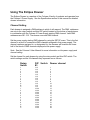
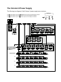
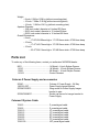
User Manual
1K Model #9001 – 8-inch aperture dowser
2K Model #11010 – 10-inch aperture dowser
5K Model #17000 – 16-inch aperture dowser
Eclipse Dowser software version: 3.3
Eclipse User Manual part number: 901-08-01
Manual revision: April 14, 2003
CONTENTS:
Introduction................................................................3
Getting Started Quickly ................................... .... ...3
The Coloram II System Diagram ...................... .... ...4
Using the Eclipse Dowser .........................................5
Channel Setting ..............................................5
LED and DIP Switch Functions .......................6
LED Function Explanation ...............................6
DIP Switch Function Explanation ....................7
Operating Modes ............................................7
Signal and Power................................... .... ...7
Coloram Cable ....................................... .... ...8
Fan Speed Control ................................. .... ...8
The Coloram II Power Supply .......................... .... ...9
Specifications...........................................................10
Parts List..................................................................11
Warranty Information ...............................................11
2
Introduction
The Coloram II System consists of mechanical dowsers, scrolling color changers, gobo
changers and power supplies in a complete range of models offering ease of setup and
use.
The lightweight dowsers and color changers slide easily into the gel frame holder of the
light fixture. The compact Coloram II Power Supply attaches easily to the truss of the
lighting rig or mount into a 19-inch rack.
The DMX512 control signal from the lighting board is connected to the power supply
and can continue on to more Coloram II Power Supplies or other DMX controlled
devices. The power supply sends both power and control signal on a single cable
eliminating the need for a separate power cable for each dowser.
The Coloram II System is equipped with the Intelligent Diagnostic System (IDS). Status
information is sent from each of the Eclipse dowsers and Coloram II Color Changers to
the Coloram II Power Supply.
Caution: The Coloram II System is not compatible with the Forerunner
System. Do not connect Coloram II Color Changers to Forerunner Power
Supplies, or Forerunner Color Changers to Coloram II Power Supplies.
Damage from such action will not be covered by the Coloram II or
Forerunner warranties.
Getting Started Quickly
Channel Setting
Set channels as follows for operation on DMX channel 1:
1.
2.
3.
4.
Set the Coloram II power supply starting channel to 1
Set the Eclipse dowser rotary switch to 1
Set the Eclipse dowser DIP switch #1 to DMX control
Set the Eclipse dowser DIP switch #3 to CHANNEL RANGE 1-12
Cable Connections
1.
2.
3
Connect the Eclipse dowser to the Coloram II Power Supply
Connect the Coloram II Power Supply to the DMX source
Operation
1.
Vary the level of DMX channel #1 to open and close the dowser vanes.
The Coloram II System Diagram
The following diagram shows how Coloram II products connect to the power supply and
other Coloram II products.
DMX512DMX Control consoleAC PowerGoboram II Gobo ChgrColoram IIColor ChangerTo additionalColor Changersor Gob
DMX CONSOLE
Figure 1
The Coloram II System Connection Diagram
4
Using The Eclipse Dowser
The Eclipse Dowser is a member of the Coloram II family of products and operates from
the Coloram II Power Supply. See the Specification section of this manual for detailed
dowser information.
Channel Setting
Each dowser is assigned a DMX address to which it will respond. The DMX addresses
are set via the rotary switch and third DIP switch located on the bottom of each dowser
in combination with the Coloram II Power Supply starting DMX channel. Valid DMX
addresses are 001- 512. The dowser uses one DMX channel.
Set the power supply starting DMX channel by using the SETUP menu. This is the first
channel in a block of consecutive DMX channels assigned to that power supply. The
channel numbers assigned to, or designated for, the dowsers will be within the lower
half of the block of DMX channels displayed at the power supply.
Note: See the Coloram II User Manual for more information on the power supply and
channel setting.
Set the channel for each dowser by using the rotary switch and third DIP switch. The
switch settings and the 24 channels they represent are as follows:
5
Rotary
Switch
DIP Switch
#3
Dowser channel
1
2
3
4
5
6
7
8
9
A
B
C
1
2
3
4
5
6
7
8
9
A
B
C
1-12
1-12
1-12
1-12
1-12
1-12
1-12
1-12
1-12
1-12
1-12
1-12
13-24
13-24
13-24
13-24
13-24
13-24
13-24
13-24
13-24
13-24
13-24
13-24
1
2
3
4
5
6
7
8
9
10
11
12
13
14
15
16
17
18
19
20
21
22
23
24
The formula for calculating DMX channels is as follows:
DMX channel = Dowser channel + Power Supply starting channel -1
Example:
DMX channel (221) = dowser channel (20) + power supply starting
channel (202) -1
Note: Eclipse Dowsers can only be addressed to the first 24 channels of the 48
channel block displayed on the power supply.
Note: The cowsers will not respond to the DMX signal until you exit the DMX channel
selection (SETUP) menu.
LED and DIP Switch Functions
The function of the LEDs and the DIP switch on the Eclipse dowsers are as follows:
LED
Indicates
------------------------------------Yellow
Local Control
Red
Reserved
Red
Low Voltage
Green
All
Flashing
Power
Shutdown
DIP Switch #
Function
--------------------------------------------------------------------1
DMX or Local control
2
Snap mode ON / OFF
3
Channel Range 1-12 or
13-24
4
Reserved
LED Function Explanation
The Yellow LED indicates Local Control when lit and DMX control when not lit.
The Red LED (nearest the Green LED) indicates low voltage -- less than 22VDC. The
dowser will operate with this LED lit but if it is lit continuously, it alerts you to the fact
that the voltage is low and the Coloram II cable to the Coloram II Power Supply may be
too long.
The Green LED indicates the dowser has 24VDC power.
If all the LEDs are flashing, the voltage has dropped below 15VDC for more than one
second and the dowser has shut itself down. It cannot operate properly below 15VDC.
The voltage typically drops this low if the Coloram II cable is too long -- the 1000 headfeet limit has been exceeded. You must shorten the Coloram II cable to solve this
problem.
6
DIP Switch Function Explanation
DIP switch #1 selects DMX control or Local Control. See the OPERATING MODES
information below.
DIP switch #2 selects SNAP MODE ON or OFF. If the Snap Mode is OFF, and control is
set to LOCAL, the Local Control buttons will open and close the vanes over a period of
five seconds. If the Snap Mode is ON, and control is set to LOCAL, the Local Control
buttons will open and close the vanes very quickly. Snap Mode has no effect when in
the DMX control mode.
DIP switch #3 sets the channel range to 1 thru 12 or 13 thru 24. See the CHANNEL
SETTING information above.
Operating Modes
The Eclipse dowser has three modes of operation. In all cases, the Coloram II power
supply is needed for control and power. DIP switch #1 on the dowser selects the control
mode -- DMX or local.
1.
DMX512 control -- the level (0-100%) of the DMX channel to which the dowser is
addressed determines the vane position. The vanes will be closed at 0% and will
be open at 100%.
2.
Local wired pendant control -- a hand held pendant can be attached via a 3-pin
XLR cable to manually open and close the vanes. Movement from fully open to
fully closed or visa versa takes 5 seconds - this allows precise vane positioning.
Press the "+" button to open the vanes and the "-" button to close them. Either
the pendant buttons or the buttons on the dowser itself can be used in this mode.
The wired pendant cable can be up to 1000 feet long.
3.
Local push button control -- the dowser unit has two momentary push button
switches to manually open and close the vanes. Movement from fully open to
fully closed or visa versa takes 5 seconds - this allows precise vane positioning.
Press the "+" button to open the vanes and the "-" button to close them. Either
the pendant buttons or the buttons on the dowser itself can be used in this mode.
Signal and Power
The Eclipse Dowser uses a Coloram II Power Supply and Coloram II cable for control
signal and 24VDC power. The dowser can be daisy chained with Coloram II Color
Changers and Goborams. Vane position is determined by the DMX level (0-100%) of
the DMX channel to which the dowser is addressed. The dowser uses one DMX
channel.
7
Coloram Cable
Connect the dowsers to the Coloram II Power Supply using the 4-pin Coloram II Cable.
There is a limit to the number of dowsers/color changers and total cable lengths used
on one "home run". This is measured in "head-feet".
The definition of head-feet is THE SUM OF THE CABLE LENGTHS FROM EACH
DOWSER OR COLOR CHANGER TO A SINGLE POWER SUPPLY OUTPUT
CONNECTOR. See the Coloram II User Manual for a complete explanation of "headfeet".
The head-feet limit for the Eclipse dowser is 1000 head-feet.
If a daisy chain consists of different models, use the model with the least amount of
"head feet" for the calculation. See the Coloram II User Manual for head-feet figures of
other Coloram II products.
Fan Speed Control
The fan in the Eclipse Dowser is small and cools electronics enclosure. Therefore, it
always runs at full speed and CANNOT be slowed or stopped.
8
The Coloram II Power Supply
The following is a diagram of the Coloram II power supply menu structure.
The
The
The
symbol means to push the
symbol means to push the
symbol means to push the
DISPLAY
/ENTER button to get to the next display as indicated.
+ button to get to the next display as indicated.
- button to get to the next display as indicated.
_
+
/ENTER
INTRO
ROLLCALL
XX UNITS
1 -- X
SETUP
COMMANDS
OPTIONS
NO DMX PROCESSING
DMX OK
*ALERT*
DMX ALL
# of ALERTS
Re-Init
SHUTDOWN
SEND ?
SEND ?
ALERT DETAILS
APPEAR HERE.
PRESS
FOR
ADD’L ALERTS
YES
NO
YES
POS 000
POS ? XXX
Mtr NORM
Fan LOW
Fan ? LOW
NORM
LOW
NO
Mtr ? LOW
NORM
LOW
NO DMX
PROCESSING
Disp %
Run REG
Reset NO
DISP ?
Run ? xxx
RESET ?
DEC
%
HEX
REG
MIN
OK
NO
NO DMX PROCESSING
NOTE: THIS DISPLAYS EACH
CHANNEL WITH A CONNECTED
DEVICE. RETURN HERE AND
PRESS
TO GET INFO ON
THE NEXT DEVICE.
INDIVIDUAL MENUS
FOR EACH DEVICE:
Chan 001
Mode CR2
CHAN ?
MODE ?
Tbck OFF
Jttr OFF
DMXF OFF
FChn XXX
JTTR ?
DMXF ?
FChn ?
Foff OFF
DMX xxx
1 OF x
ColoRAM
CR1
DCV 24
POS 000
TBCK ?
CR2
ON
Fan NORM
OFF
ON
Mtr NORM
OFF
Ver x.x
OFF
ONE
BLK
Foff ?
ON
IDENTIFY
= to Initialize
OR…
CXI
DCV 24
Frt %
Bck %
Fan NORM
Ver x.x
IDENTIFY
= to Initialize
OR…
GoboRAM
DCV 24
POS 000
Rot 000
Spin OFF
Ver x.x
IDENTIFY
= to Initialize
OR…
Eclipse
DCV 24
POS 000
Fan NORM
Mtr NORM
Ver x.x
IDENTIFY
= to Initialize
9
OFF
Specifications
Vane speed (under DMX control):
-- fast cut: 200 milliseconds (fully open to fully closed and visa versa)
-- strobe rate: 100 milliseconds (60% amplitude)
-- cross fade: up to 60 seconds (movement without stopping)
Operating modes:
1.
DMX512
2.
Local wired pendant control
3.
Local push button control (push buttons on the dowser unit)
Number of DMX channels used:
-- one
LED Indicators:
1.
Yellow -- DMX or Local control
2.
Red -- reserved
3.
Red -- low voltage (less than 22 VDC)
4.
Green -- power
5.
All flashing -- shutdown
DIP Switch Functions:
1.
DMX or local control
2.
Snap Mode ON / OFF
3.
Channel Range 1-12 or 13-24
4.
reserved
Control Pendant 3-pin XLR connector pin functions:
-- Pin 1 -- connect to common to open the vanes
-- Pin 2 -- connect to common to close the vanes
-- Pin 3 -- common
Current Requirements:
-- 0.25 amp average @ 24VDC
-- 1.0 amp peak @ 24VDC
Fuse:
-- 1.5 amp Slo-Blo
Mounting Plates:
-- various plates available to fit a wide variety of fixtures
Wired Pendant control cable:
-- 3 conductor with 3-pin XLR connectors
-- up to 1000 feet long
Fan:
-- small, low speed fan to cool the electronics enclosure
Safety Cable:
-- 3.5 feet long cable included
Daisy Chaining:
-- individual ID's on one home run
Power Supply Compatibility:
-- Coloram II Power Supply only
Signal Termination:
-- none required
10
Weight:
-- 8-inch: 6.54 lbs./2.96 kg (without mounting plate)
-- 10-inch: 7.26lbs./3.29 kg (without mounting plate)
-- 16-inch: 11.94 lbs./5.41 kg (without mounting plate)
Aperture Diameter:
-- 1K/8-inch model: diameter is 8 inches/203.2mm
-- 2K/10-inch model: diameter is 10 inches/254mm
-- 5K/16 inch model: diameter is 16 inches/406.4mm
Overall Dimensions:
-- 8 inch:
-- 17.09"/434.09mm high x 11"/279.4mm wide x 2"/50.8mm deep
-- 10 inch:
-- 17.47"/443.74mm high x 13"/330.2mm wide x 2"/50.8mm deep
-- 16 inch:
-- 23.47"/596.14mm high x 19"/482.6mm wide x 2"/50.8mm deep
Parts List
To order any of the following items, contact you authorized WYBRON dealer.
9001 .................................……………1K Model – 8-inch Eclipse Dowser
11010 ...................................…………2K Model – 10-inch Eclipse Dowser
17000 ...................................………...5K Model – 16-inch Eclipse Dowser
11010-1 ...............................…………Control Pendant
Coloram II Power Supply and accessories
20240 ............................................... Coloram II Power Supply - 24 Way
1900-01-05P..................................... Power Supply hanger bracket
SCRWC252075 ................................ Wing screw for Power Supply hanger
bracket to pipe
SCRSC2520037 ............................... Socket cap screw for hanger bracket to
Power Supply
Coloram II System Cable
7042-3 .............................................. 3' power/signal cable
7042-5 .............................................. 5' power/signal cable
7042-10 ............................................ 10' power/signal cable
7042-15 ............................................ 15' power/signal cable
7042-25 ............................................ 25' power/signal cable
7042-50 ............................................ 50' power/signal cable
7042-75 ............................................ 75' power/signal cable
7042-100 .......................................... 100' power/signal cable
11
Warranty information
WYBRON, INC. warrants to the original owner or retail customer that for a period of one
year from date of delivery of a portable system or energization of a permanently
installed system (up to a maximum of 18 months from delivery) its products will be free
from defects in materials and workmanship under normal use and service.
Warranty does not cover any product or part of a product subject to accident,
negligence, alteration, abuse, misuse or any accessories or parts not supplied by
WYBRON, INC.. Warranty does not cover "consumable" parts such as fuses, lamps, or
color media. WYBRON, INC.'s warranty does not extend to items not manufactured by
us. Freight terms on warranty repairs are FOB WYBRON, INC. factory or designated
repair facility. Collect shipments or freight allowances will not be accepted.
WYBRON, INC.'s sole responsibility under this warranty shall be to repair or replace at
WYBRON, INC.'s option such parts as shall be determined to be defected on
WYBRON, INC.'s inspection. WYBRON, INC. will not assume any responsibility for any
labor expended or materials used to repair any equipment without WYBRON, INC.'s
prior written authorization . WYBRON, INC. shall not be responsible for any incidental,
general or consequential damages to property, damages for loss of use, time, profits or
income, or any other charges.
The owner's obligations during the warranty period under this warranty are to notify
WYBRON, INC. at WYBRON, INC.'s address within one week of any suspected defect,
and return the goods prepaid to WYBRON, INC. at their factory or authorized service
center.
This warranty is contingent on the customer's full and timely compliance with the terms
of payment set forth in said purchase order. This warranty is expressly in lieu of any
and all other warranties expressed or implied including the warranties of merchantability
and fitness for a particular purpose and of other obligations and liabilities on our part.
The owner acknowledges that no other representations were made to him or relied
upon him with respect to the quality and function of the goods sold.
This written warranty is intended as a complete and exclusive statement of the terms
thereof. Prior dealings or trade usage shall not be relevant to modify, explain or vary
this warranty. Acceptance of, or acquiescing in, a course of performance under this
warranty shall not modify the meaning of this agreement even though either party has
knowledge of the performance and a chance to object.
WYBRON, INC.- TEL719-548-9774- FAX719-548-0432Email:[email protected] us on the World Wide Web athttp://www.wybr
12