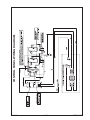
1
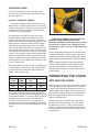
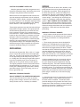
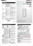
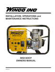
HPS9000VE/E
INSTALLATION AND
OPERATORS MANUAL
TRI-FUEL GENERATOR
SAVE THESE INSTRUCTIONS
PROPER USE AND INSTALLATION
This manual contains important instructions that
should be followed during installation and maintenance of the generator and battery. Read and
understand all instructions in the manual before
starting and operating the generator set.
You must be sure your new engine generator set is:
* Properly serviced before starting.
* Operated in a well ventilated area.
* Properly exhausted and gases safely
dispersed.
* Operated only for its designed purposes.
* Used only by operators who understand
its operation.
* Properly maintained.
USING THE MANUAL
Congratulations on your choice of a Winco generator set. You have selected a high-quality, precision
engineered generator set designed and tested to
give you years of satisfactory service.
COPY YOUR MODEL AND
SERIAL NUMBER HERE
To get the best performance from your new engine
generator set, it is important that you carefully read
and follow the operating instructions in this manual.
No other WINCO generator has the same serial
number as yours. It is important that you record
the number and other vital information here. If you
should ever need to contact us on this unit it will help
us to respond to your needs faster.
Should you experience a problem please follow
the “Troubleshooting Tables” near the end of this
manual. The warranty listed in the manual describes
what you can expect from WINCO should you need
service assistance in the future.
MODEL
TABLE OF CONTENTS
PURCHASE DATE_________________________
INTRODUCTION
BASIC INFORMATION
Specifications
SAFETY INFORMATION
UNIT CAPABILITIES
PREPARING THE UNIT
Unpacking the Unit
LP/NG Installation
Fuel Line Sizing
Fuel Consumption
Fuel Pressure
Changing Fuel Types
Battery Installation
INITIAL START UP
Basic Operation
Manual Starting (Gasoline only)
Electric Starting (Gasoline)
Electric Starting (LP/NG)
Stopping & Storage
Operating Speed
CONNECTING THE LOADS
Wiring
ENGINE CARE
GENERATOR CARE
TROUBLESHOOTING
CONTROL PANEL WIRING DIAGRAM
WARRANTY INFORMATION
3210-10
2
2
3
4
5
6
7
7
7
8
9
10
10
10
11
11
12
12
13
14
15
16
17
18
2
HPS9000VE/E
SERIAL NUMBER_________________________
DEALER_________________________________
DEALER PHONE # ________________________
UNIT SPECIFICATIONS
GENERATOR MODEL
Surge Watts
Continuous Watts
Volts
Amps
Engine
Generator
HPS9000VE
9,000
8,000
120/240
67/33
Briggs and Stratton
305447-0003-G1
Mecc Alte Spa
S20W-110/
60706-237
b. Keep fuel containers out of reach of children.
c. Do not smoke or use open flame near the
generator set or fuel tank.
d. Keep a fire extinguisher nearby and know its
proper use. Fire extinguishers rated ABC by
NFPA are appropriate.
e. Store fuel only in an approved container, and
only in a well ventilated area.
f. Follow local codes for closeness to
combustible material.
SAFETY INFORMATION
This engine generator set has been designed and
manufactured to allow safe, reliable performance.
Poor maintenance, improper or careless use can
result in potentially deadly hazards; from electrical
shock, exhaust gas asphyxiation, or fire. Please
read all safety instructions carefully before installation or use. Keep these instructions handy for future
reference. Take special note and follow all warnings
on the unit labels and in the manuals.
3. DEADLY EXHAUST GAS Exhaust fumes from
any gasoline engine contain carbon monoxide, an invisible, odorless and deadly gas that must be mixed
with fresh air.
a. Operate only in well ventilated areas.
b. Never operate indoors including attached
garages
c. Never operate the unit in such a way as to
allow exhaust gases to seep back into closed
rooms (i.e. through windows, walls, floors).
ANSI SAFETY DEFINITIONS
***********************************************************
DANGER:
DANGER indicates an imminently hazardous situation which, if not avoided, will result in death or
serious injury. This signal word is to be limited to the
most extreme situations.
***********************************************************
4. NOISE HAZARD Excessive noise is not only
tiring, but continual exposure can lead to loss of
hearing.
a. Use hearing protection when working around
this equipment for long periods of time.
b. Keep your neighbors in mind when using this
equipment.
***********************************************************
WARNING:
WARNING indicates a potentially hazardous situation which, if not avoided, could result in death or
serious injury.
***********************************************************
***********************************************************
5. CLEANLINESS Keep the generator and surrounding area clean.
a. Remove all grease, ice, snow or materials that
create slippery conditions around the unit.
b. Remove any rags or other materials that could
create a potential fire hazard.
c. Carefully clean up any gas or oil spills before
starting the unit.
CAUTION:
CAUTION indicates a potentially hazardous situation which, if not avoided, may result in minor or
moderate injury. It may also be used to alert against
unsafe practices.
***********************************************************
1. ELECTRICAL SHOCK The output voltage present in this equipment can cause fatal electric shock.
This equipment must be operated by a responsible
person.
a. Do not allow anyone to operate the generator
without proper instruction.
b. Guard against electric shock.
c Avoid contact with live terminals or
receptacles.
d Use extreme care if operating this unit in rain
or snow.
e. Use only three-pronged grounded receptacles
and extension cords.
f. Be sure the unit is properly grounded to an
external ground rod driven into the earth.
6. SERVICING EQUIPMENT All service, including the installation or replacement of service parts,
should be performed only by a qualified technician.
a. Use only factory approved repair parts.
b. Do not work on this equipment when fatigued.
c. Never remove the protective guards, covers,
or receptacle panels while the engine is
running.
d. Use extreme caution when working on
electrical components. High output voltage
from this equipment can cause serious injury
or death.
e. Always avoid hot mufflers, exhaust manifolds,
and engine parts. They can cause severe
burns instantly.
f. The use of the engine-generator set must
comply with all national, state, and local
codes.
2. FIRE HAZARD Gasoline and other fuels present a hazard of possible explosion and/or fire.
a. Do not refuel when the engine is running or
hot.
3210-10
3
60706-237
TESTING POLICY
UNIT CAPABILITIES
Before any generator is shipped from the factory, it
is fully checked for performance. The generator is
loaded to its full capacity, and the voltage, current
and frequency are carefully checked.
Rated output of generator is based on engineering
tests of typical units, and is subject to, and limited
by, the temperature, altitude, fuel, and other conditions specified by the manufacturer of the applicable
engines.
INTENDED USES
This engine generator set has been designed primarily for portable heavy duty commercial use. Both
120 volt and 240 volt receptacles are provided in the
control panel to plug in your loads (lights, portable
tools, and small appliances). These units are dual
wound generators, therefore the 120 volt loads must
be equally split with 1/2 of the rated capacity available on each of the two 120 volt circuits.
GENERATOR CONNECTIONS
HPS9000VE: 120 volt and 240 volt receptacles
are provided for connection to various loads. The
diagram below represents this 8,000 watt (rated
output) generator. A & B represent the 120 volt output legs of this generator. Up to 4000 watts at 120
volts (33 Amps) can be drawn from the receptacles
attached to either A or B output legs. This generator
is capable of producing 33 Amps of 240 volt current
at C.Check the appliance or tool nameplates for the
current and voltage to insure compatibility. Remember that power taken from C reduces the power
available at equally both A and B and vice versa.
This portable unit requires large quantities of fresh
air for cooling the engine and generator. For safety,
long life and adequate performance, these units
should never be run in small compartments without
positive fresh air flow.
STARTING ELECTRIC MOTORS
RESTRICTED USES
DO NOT remove from the cradle assembly. Removal of the generator from the cradle assembly
may cause excessive vibration and damage to the
engine-generator set.
DO NOT install and operate this generator in a small
compartment., i.e. generator compartments of vehicles, motor homes or travel trailers. These compartments will not allow enough free flow of fresh
air to reach the engine generator set for cooling and
will cause the unit to overheat, damaging both the
engine and generator. Small compartments will also
develop hot spots where there is very little air flow
and may cause a fire.
PLEASE NOTE There are 3rd party companies
making enclosures for generators that have been
properly engineered. The use of these 3rd party
enclosures is acceptable as long as they have been
certified and meet current code.
DO NOT attempt to operate at 50 cycles. These
units are designed and governed to operate at 60
cycles only.
3210-10
4
Electric motors require much more current (amps) to
start them than to run them. Some motors, particularly low cost split-phase motors, are very hard
to start and require 5 to 7 times as much starting
current as running current. Capacitor motors are
easier to start and usually require 2 to 4 times as
much starting current as running current. Repulsion
Induction motors are the easiest to start and require
only 1 1/2 to 2 1/2 times as much starting as running
current.
Most fractional horsepower motors take about the
same amount of current to run them whether they
are Repulsion Induction (RI), Capacitor (Cap), or
Split-Phase (SP) type.
If the electric motor is connected to a hard starting
load such as an air compressor, it will require more
starting current. If it is connected to a light load,
or no load such as a power saw, it will require less
starting current. The exact requirement will also
vary with the brand or design of the motor.
60706-237
Self-exciting generators respond to severe overloading differently than utility power. When overloaded,
the engine is not able to supply enough power to
bring the electric motor up to operating speed. The
generator responds with high initial starting current,
but the engine speed drops sharply. The overload
may stall the engine. If allowed to operate at very
low speeds, the electric motor starting winding will
burn out in a short time. The generator winding
might also be damaged.
LUBRICATION
Before starting the engine, fill the crankcase to the
proper level with a good quality oil. The recommended grade of oil and quantity of oil required is
listed in the engine operator’s manual and under the
service tab in this manual. This unit was shipped
with most of the oil removed. The engine normally
holds 46 to 48 ounces of oil. Since there is some
trapped oil in the engine, when filling the crankcase
the first time use the dipstick (ref “A”) to ensure that
you do not over fill the crankcase. Reference “B”
shows the full oil level mark on the dipstick.
CAUTION: EQUIPMENT DAMAGE
RUNNING THE GENERATOR SET UNDER
THESE CONDITIONS MAY RESULT IN DAMAGE
TO THE GENERATOR STATOR AS WELL AS THE
MOTOR WINDING.
C
A
The heavy surge of current required for starting
motors is required for only an instant. The generator will not be damaged if it can bring the motor up
to speed in a few seconds of time. If difficulty is
experienced in starting motors, turn all other electrical loads off and if possible reduce the load on the
electric motor.
A
B
PREPARING THE UNIT
Oil is added to the engine by removing the oil fill cap
(ref “C”) and adding oil at this point. After filling the
crankcase to the proper level, be sure you properly
tighten the oil fill cap. NOTE: This engine generator
must be on a level surface before you check or add
oil to the system.
UNPACKING
CAUTION: EQUIPMENT DAMAGE
THIS UNIT HAS BEEN SHIPPED WITHOUT OIL.
Failure to maintain the engine oil at the proper level
will result in serious engine damage.
The necessity of using the correct oil, and keeping
the crankcase full cannot be overemphasized. Engine failures resulting from inadequate or improper
lubricant are considered abuse and not covered by
the generator or engine manufacturer’s warranty.
When you unpack your new engine-generator set be
sure to remove all the information sheets and manuals from the carton.
Oil Recommendations
1. This generator-set was in good order when
shipped. Inspect the generator-set promptly after
receiving it. If any damage is noted, notify the transportation company immediately; request proper procedures for filing a “concealed damage” claim. Title
to the equipment and responsibility for filing a claim
rests with you when a generator-set is sent F.O.B.
shipping point. Only you can legally file a claim.
Outdoor temperatures determine the proper oil
viscosity for the engines. Use the chart to select the
best viscosity for the outdoor temperature range
expected.
5
5W-30
Synthetic 5W-30
10W-30
2. Before proceeding with the preparations of your
new generator-set for operation, take a couple of
minutes to insure the unit you have received is the
correct model and review the specification pages in
this manual to insure that this unit meets your job
requirements.
3210-10
°C
SAE 30
°F
60706-237
Oil Recommendations Con’t
LP/NG FUEL INSTALLATION
* Below 40OF (4OC) the use of SAE30 will result in
hard starting.
** Above 80OF (27OC) the use of 10W-30 may cause
increased oil consumption. Check oil level more
frequently.
The information in this instruction is offered to assist
you in providing the proper vapor fuel supply for your
engine. This information is only provided to advise
you of the engine’s requirements and the decisions
you must make. In no case should this information be
interpreted to conflict with any local, state or national
code. If in doubt, always follow local codes.
Briggs & Stratton recommends the use of their warranty certified oils for best performance. Other highquality detergent oils are acceptable if classified for
service SF, SG, SH SJ or higher. Do not use special
additives.
GASOLINE
When using gasoline, always use fresh, clean,
unleaded fuel. This engine is certified to operate on
unleaded gasoline with a minimum octane rating of
87 or higher. Gasoline containing no more than 10%
ethanol is acceptable.
CAUTION: EQUIPMENT DAMAGE
Do not use unapproved gasolines, such as E15 or
E85. Do not mix oil in the gasoline. Use of unapproved fuels will damage the engine components
and void the engine warranty.
DANGER: FIRE - PERSONAL INJURY All fuel lines must be installed by a qualified fuel
supplier.
The fuel source should be as close as possible to
the outdoor operating location. This will reduce the
installation cost of fuel runs. Connect the fuel supply
line to the inlet of the fuel demand regulator on the
unit using a locally approved flexible fuel line (see
table for recommended line size). The pressure
supplied to the demand regulator must be FOUR
TO SIX OUNCES or 7 to 11 INCHES W.C. (water
column). The primary regulator at the fuel supply
must be capable of delivering the proper volume of
fuel at this pressure.
Use of fuels with content of ethanol greater than
shown above may cause starting and/or performance problems. Always insure that the fuel is
clean and free of all impurities.
Have your local fuel supplier install a protected fuel
connection at the outside operating location. He
should also install a lockable fuel shut off valve at the
connection point. Have your fuel supplier permanently install a flexible fuel line to the demand regulator on
the engine generator set.
WARNING: FIRE DANGER
DANGER: FIRE - PERSONAL INJURY -
Gasoline and its fumes are VERY explosive when
proper precautions are not taken.
The LP/NG fuel supply line must always be shut off
when the engine is not running. Failure to do so may
allow fuel to leak at the unit.
Never use gasoline that has been stored for an extended period of time as the fuel will lose its volatile
properties and you will be left with varnish residue.
The varnish like substance will clog the carburetor
and will not burn properly.
The use of fuel additives, such as STA-BIL, or an
equivalent will minimize the formation of fuel gum
deposits. If a unit has been out of operation for an
extended period of time, it is best to drain old fuel
from the engine and replace with fresh fuel before
attempting to start.
See the engine manual for special instruction for
operating this unit at over 5000 feet
3210-10
6
INSTALLING THE FUEL LINE
DANGER: PERSONAL INJURY
Units that are intended to be run unattended
MUST have an electric fuel solenoid installed. This
solenoid MUST be wired to AUTOMATICALLY turn off
the fuel whenever the engine stops.
Unit location will determine the size of fuel line that
is required to supply the engine with a constant fuel
pressure. Refer to the tables below for fuel line size,
and recommended tank size. For distances of 100
feet and over, a two regulator fuel system is recommended. This system consisting of a primary 10-15#
regulator at the tank and a 6 ounce secondary regulator installed about 10 feet from the generator.
60706-237
You need to run a 3/4 inch line or larger from the secondary regulator to the engine-generator set. When
a two (2) regulator fuel system is used, a fuel line
size of 3/8 inch is generally adequate for distances
up to 300 feet. The line size from the table below
applies to the distance from the second regulator to
the demand regulator. A positive fuel shut-off device must be installed in the fuel line close to the
engine generator set. This may be either a lockable
manual shut-off valve available from your local fuel
installer, or a 12 volt DC fuel solenoid valve. This
optional 12 volt DC valve is available through your
local Winco dealer.
FUEL PRESSURE
Correct fuel pressure cannot be stressed enough.
The most common cause for inoperative systems is
an inadequate or incorrect fuel pressure. Power and
performance of the engine is in direct relation to the
correctness of the fuel system. Shown below is a
block diagram of a typical L.P. or N.G. installation.
The fuel line used to connect the supply line to the
demand regulator must be a locally approved flexible
fuel line. Products used will vary in different regions
depending on availability and local codes. Consult
with your local fuel supplier to insure complete compliance with ALL codes.
1. Remove the pipe plug from the demand regulator.
2. Connect the flex fuel line to the demand regulator
to the optional fuel solenoid..
Reference numbers 1 through 3 in the block diagrams above are system parts supplied by customer.
DANGER: PERSONAL INJURY
Do not use galvanized pipe in the fuel line runs.
The galvanized coating will become eroded and flake
off, causing possible obstruction or damage to the
regulator or fuel valve. The obstruction could cause
an inoperative engine or an explosive fuel leak.
Reference number 4 is the engine generator set.
Below is a table of the fuel pressure reading at each
reference in the system.
Fuel Pressure Table
Size of pipe required for generators operating on
natural gas/LP gas.
Single Regulator (L.P. Vapor only)
1
Length of Fuel Line* Fuel Line Size
less than 25 feet
3/4 inch black pipe
25 to 100 feet
1 inch black pipe
over 100 feet
not recommended**
*allow an additional 3 feet for each standard elbow.
Do not use ‘street ells’ (restrictive)
** Consult factory for fuel runs over 100 feet.
UNIT OFF
DANGER! - FIRE - PERSONAL INJURY Be careful when sealing gas joints. Excessive
sealing compound can be drawn into the solenoid,
regulator or carburetor causing an engine malfunction
or dangerous fuel leak.
TANKPSI
STARTING
TANK PSI
NO LOAD
TANK PSI
FULL LOAD
TANK PSI
3
4
7-11 in
7-11 in
4-6 oz
4-6 oz
7-11 in
7-11 in
4-6 oz
4-6 oz
7-11 in
7-11 in
4-6 oz
4-6 oz
7-11 in
7-11 in
4-6 oz
4-6 oz
FUEL CONSUMPTION (Full Load)
Gasoline
LP Vapor
Natural Gas
3210-10
1.63Gal/HR
1.9 Gal/HR
180 cu ft/hr
173,850 BTU
180,000 BTU
7
60706-237
must be between 4 and 6 oz. (7-11 inches of water
column). Any lower pressure and the unit will starve
for fuel under load. Any higher and the unit will ‘flood’
when attempting to start.
LP TANK SIZING
Once above the minimum acceptable size, the size
of L.P. tank used will generally depend on how long
you want the unit to run without refilling. The tank
sizes shown below are the smallest recommended
tank sizes based on the outside temperature. Keep
in mind the colder it gets the slower L.P. will vaporize.
This is the reason for the larger tanks at low temperature. Minimum sizing is not based on running time.
Two (2) Regulator System (L.P. Vapor only)
1
2
3
4
UNIT
TANK
10-15 lbs
7-11 in
7-11 in
OFF
PSI
4-6 oz
4-6 oz
STARTING
TANK
10-15 lbs
7-11 in
7-11 in
4-6 oz
4-6 oz
10-15 lbs
7-11 in
7-11 in
4-6 oz
4-6 oz
7-11 in
7-11 in
4-6 oz
4-6 oz
PSI
NO LOAD
TANK
PSI
FULL
TANK
LOAD
PSI
10-15 lbs
Temp f.
STARTING
NO LOAD
FULL LOAD
30 deg
0 deg
-20 deg
150 gal
250 gal
500 gal 1000 gal
CHANGING FUEL TYPES
These engine generator sets are designed to run
on three different fuels; gasoline, natural gas or LP
vapor. They may be easily changed from one fuel to
another.
FROM GASOLINE TO LP/NG
1. With the engine running turn off the gasoline
fuel valve.
2. Run the engine until it runs out of fuel.
3. Remove the pipe plug from the demand
regulator.
4. Install locally approved flexible fuel line.
5. Connect the LP/NG vapor fuel line.
6. This unit have two different hose fittings on
the top of the demand requlator. One is for
LP and one is for Natural Gas. Make sure the
hose is attached to the proper fitting.
7. Turn on the vapor fuel.
8. Start the engine.
9 . Apply the load to the generator.
Natural Gas
UNIT OFF
60 deg
1
3
4
LINE PSI
7-11 in
7-11 in
4-6 oz
4-6 oz
LINE PSI
LINE PSI
LINE PSI
7-11 in
7-11 in
4-6 oz
4-6 oz
7-11 in
7-11 in
4-6 oz
4-6 oz
7-11 in
7-11 in
4-6 oz
4-6 oz
Remember that whichever fuel delivery system or
type of vapor fuel used, the fuel pressure at the
demand regulator installed on the engine generator
3210-10
8
60706-237
FROM LP/NG TO GASOLINE
Amp Hours: 15AH or greater. Follow the battery
manufacturers recommendations for servicing and
charging prior to use. Connect the battery to the electric start system using the cables provided.
1. With the engine running turn off the LP/NG
fuel supply.
2. Run the engine until it runs out of fuel.
3. Remove the flexible fuel line from the demand regulator.
4. Reinstall the plastic plug in the regulator.
5. Check to be sure the gasoline fuel valve is
off.
6. Fill the gasoline fuel tank.
7. Turn on the gasoline fuel valve.
8. Start the engine.
CAUTION: EQUIPMENT DAMAGE
These electric start engines are NEGATIVE
GROUND. Use extreme caution when connecting the
battery. Connect the NEGATIVE battery terminal to
GROUND.
For your safety always connect the positive battery
cable to the “bat+” terminal first. Then connect the
negative battery cable to the “bat-” terminal. Make
sure all connections are clean and tight. Reverse the
sequence when disconnecting, disconnect the negative cable first. These engines produce enough direct
current to keep a battery charged under normal operating conditions, but were not intended to be used as
a battery charger.
BATTERY INSTALLATION
This engine generator set is shipped with a battery tie
down kit for customer installation. This kit consists of
a battery tie down and hardware for installation of the
customer supplied battery on the unit. If you intend
to use the power plant’s electric start system, you will
need to purchase and install a battery to operate it.
Units equipped with a recoil or rope start will operate
satisfactorily on gasoline without a battery but stating
on LP/NG requires electric start be used.
WARNING: PERSONAL INJURY
Lead acid batteries produce explosive hydrogen gas when charging. Keep sparks, flames, and
burning cigarettes away from the battery. Ventilate
the area when charging or using the battery in an
enclosed space. Lead acid batteries contain sulfuric
acid, which causes severe burns. If acid contacts
eyes, skin or clothing, flush well with water. For contact with eyes, get immediate medical attention.
BATTERY CHARGING
Units equipped with electric start have a small flywheel charger built into the engine flywheel assembly
for recharging the starting battery. This flywheel charger generates a small AC current that passes through
a diode assembly to produce a DC charging current
of about 1 to 3 AMPS. This circuit is not designed to
be used as a battery charging circuit to recharge dead
batteries.
WARNING: EQUIPMENT DAMAGE
The battery positive (+) cable is shipped with a
plastic protective cap. When starting manually, this
protective cap must remain in place to avoid possible damage to the engine electrical system and/or
generator end.
OPTIONAL DOLLY KIT
An optional dolly kit is available for this generator.
The dolly kit comes with instructions and parts list.
After installing the dolly kit, file the instructions and
parts list in the back of this manual for future reference.
A 12-volt powersports (motorcycle/atv/snowmobile) battery, BCI group 20 or 24HL rated at 300
CCA or larger is recommended for this electric start
engine generator set. Maximum length: 8 1/8”,
Maximum width: 3 9/16”, Height range: 5 3/4” - 7”.
3210-10
9
60706-237
OIL ALERT SYSTEM
This WINCO generator is equipped standard with
low oil shutdown systems. The Briggs and Stratton
engine uses an oil pressure switch system. This low
oil warning system will automatically stop the engine
before the oil level reaches a critical danger point.
This feature is designed to prevent costly repairs and
downtime.
B
C
CAUTION: EQUIPMENT DAMAGE
Allowing the engine to shutdown repeatedly on
low oil level may cause excessive wear which can be
cumulative.
INITIAL START UP
The throttle control on these generators is preset and
locked to operate at 3600 RPM (nominal) with no
load speed set at 3690 RPM. Only a trained service
technician should be allowed to adjust this speed
setting.
NOTICE: ENGINE START LOCKOUT
This unit will not start if it is low on oil. The lubricating oil level must be at the full mark before the
engine will start and run.
BASIC OPERATION
MANUAL STARTING (Gasoline only)
Refer to the engine manual for additional starting,
operating, and stopping instructions.
1. Check oil level. Refill as needed
A
2. Turn on the fuel supply, Ref “A
NOTE - There is a second fuel valve under the fuel
tank that is used when removing the tank. This valve
is normally left on.
3210-10
10
3. Pull out the choke (Ref “B”) to the full “on”
position.
4 Turn the key to the run position, Ref “C”
5. Pull the starter grip lightly until resistance is felt,
then pull briskly.
6. When the engine starts, open the choke
gradually.
7. The engine should promptly come up to
operating speed.
NOTICE:
Do not allow the starter grip to snap back against
the engine. Return it gently to prevent damage to the
starter.
ELECTRIC STARTING (Gasoline only)
If the engine is cold and stiff or if the battery is not
fully charged, starting can be made easier by slowly
hand cranking the engine through the compression
stroke before pushing the starter switch. This permits
the starter to gain momentum before the heavy load
of the compression stroke occurs. This minimizes the
drain on the battery and improves the possibility of
starting under such adverse conditions. Always keep
the battery charged, especially during cold weather
operation.
1. Check oil level, refill as needed
2. Turn on the fuel supply. Ref “A”
3. Move the choke to the full “on” position. A warm
engine will require less choking than a cold
engine. Ref “B”
4. Rotate the key switch (Ref “C”) briefly to the
START position. The starter life is improved by
using shorter starting cycles with time to cool off
between cranking cycles. Do not operate the
starter more than 15 seconds during each
minute. Repeat if necessary.
5. When the engine starts, open the choke
gradually.
6. The engine should promptly come up to
operating speed.
60706-237
CAUTION: EQUIPMENT DAMAGE
STARTING HINTS
Never permit the choke to remain on after the
engine has run for a short time. It is not necessary
to choke the engine when it is warm. Avoid overchoking.
1. Cold weather
a. Use the proper oil for the temperature expected.
b. Use fresh winter grade fuel. Winter grade
gasoline is blended to improve starting. Do not
use summer grade gasoline.
ELECTRIC STARTING LP/NG only)
When operating on LP or NG, you will have to
always use the electric start to get the unit running.
Because of the engine vacuum need to activate the
fuel system it is almost impossible to manual start
the unit using LP or NG.
2. Hot weather
a. Use the proper oil for the temperature expected.
b. Use only summer blended gasoline. Using gasoline left over from winter may cause the unit to
vapor lock.
STOPPING AND STORAGE
1. Check oil level, refill as needed.
2. Turn on the LP/NG fuel supply
3. NEVER USE THE CHOKE WHEN OPERATING
ON LP or NG.
B
C
4. Rotate the key switch (Ref “C”) briefly to the
START position. The starter life is improved by
using shorter starting cycles with time to cool off
between cranking cycles. Do not operate the
starter more than 15 seconds during each
minute. Repeat if necessary.
5. When the engine starts, release the key
switch, allowing it to return to the “on” position.
6. The engine should promptly come up to
operating speed.
3210-10
1. Move the on/off switch to the “OFF” position.
2. Before extended storage (over 30 days) certain
precautions must be taken to ensure the fuel doesn’t
deteriorate and clog the fuel system.
Note: The use of a fuel additive, such as Briggs &
Stratton Advanced Fuel Treatment & Stabilizer or
an equivalent will minimize the formation of gum
deposits during storage. The additive may be added
to gasoline in the engines fuel tank or to gasoline in
a storage container.
a. Add the fuel stabilizer to the fuel in the tank and
run the unit for 2 minutes to circulate the
stabilizer throughout the fuel system.
b. If you choose to remove the remaining fuel from
the fuel tank, it must be drained into an approved
container.
c. Start the engine and allow it to run until all the
fuel in the carburetor and the fuel lines has been
used up and the engine stops.
Note: Running the engine to use up the fuel in the
lines and carburetor will still leave a small amount of
fuel in the carburetor. It is best for extended storage
to treat the fuel before draining.
d. While the engine is warm, drain the oil and refill
with fresh oil.
e Clean dirt and chaff from cylinder, cylinder head
fins, blower housing, screen and muffler areas.
f. Store in a clean and dry area.
11
60706-237
OPERATING SPEED
The engine-generator must be run at the correct
speed in order to produce the proper electrical voltage and frequency.
D
CAUTION: EQUIPMENT DAMAGE
The output voltage should be checked to insure
the generator is working properly prior to connecting
a load to the generator. Failure to do so could result
in damage to equipment plugged into the unit and
possible injury to the individual.
All engines have a tendency to slow down when
a load is applied. When the electrical load is connected to the generator, the engine is more heavily
loaded, and as a result the speed drops slightly. This
slight decrease in speed, together with the voltage
drop within the generator itself, results in a slightly
lower voltage when the generator is loaded to its full
capacity than when running no load. The slight variation in speed also affects the frequency of the output
current. This frequency variation has no appreciable
effect in the operation of motors, lights and most appliances. However, electronic equipment and clocks
will be affected if correct RPM is not maintained. See
Load vs. Output chart.
Although individual units and models vary slightly, the
normal voltage and frequency of the engine-generator described in this manual are approximately as
follows, under varying loads:
SPEED ADJUSTMENTS SHOULD ONLY BE
MADE BY A QUALIFIED SERVICE TECH.
Whenever making any speed adjustments, check
the unit with a voltmeter and a frequency meter
or tachometer and be sure the voltage and speed
are correct.
Lower voltage may damage both the generator and
any load connected to it. Running the engine at excessively high speeds results in high voltage, which
may significantly shorten the life of appliances being
used.
Output voltage should be checked periodically to
ensure continued proper operation of the generating plant and appliances. If the generator is not
equipped with a voltmeter, it can be checked with a
portable meter.
CONNECTING THE LOADS
LOAD VS. OUTPUT
Generator
Load
Speed
(RPM)
Frequency
(Hz)
Voltage
None
3690
61.5
125V
Half
3600
60.0
120V
Full
3510
58.5
115V
APPLYING THE LOADS
The speed of the engine was carefully adjusted at
the factory so that the generator produces the proper
voltage and frequency. For normal usage, the speed
setting should not be changed. If the generator
is being run continuously on a very light load, it is
often advisable to lower the operating speed slightly.
Reference “D” below is the speed adjustment for this
engine.
3210-10
CAUTION: EQUIPMENT DAMAGE
12
Allow the engine to warm up for two or three minutes
before applying any load. This will allow the engine
to reach normal operating temperature and oil to circulate throughout the engine. A short warm-up time
will permit the engine to work more efficiently when
the load is applied and will reduce the wear in the
engine, extending its life.
Receptacles have been provided to allow loads to
be connected to the generator. The loads should
be added one at a time. If a large motor is being
started; or multiple motors are being started, they
should be started individually and the largest should
be started first.
60706-237
WIRING
CAUTION: EQUIPMENT OVERLOAD
Keep the generator load within the generator and
receptacle nameplate rating. Overloading may cause
damage to the generator and/or the loads .
Most electric tools and appliances will have the voltage and amperage requirements on their individual
nameplates. When in doubt, consult the manufacturer
or a local electrician. The nameplate amperage rating
for electric motors can be misleading. See “Starting
Electric Motors” in Unit Capabilities (page 4).
These engine-generator sets are inherently self regulating based on engine speed. The engine governor
will automatically adjust itself to the load. No harm
to the generator will result if it is operated with no
load connected. Proper utilization of the receptacles
located on the control panel is necessary to prevent
damage to either the receptacles or the generator.
The generator is a limited source of electrical power,
therefore, pay special attention to the receptacle
and generator ratings. The nameplate rating can be
obtained through a single receptacle as long as the
receptacle amperage rating is not exceeded.
GROUNDING
All units must be grounded. Drive a 3/4 or 1” copper
pipe or rod into the ground close to the engine-generator set. The pipe must penetrate moist earth. Connect an approved ground clamp to the pipe. Run a
no. 10 Awg wire from clamp to the generator ground
lug on the receptacle panel. Do not connect to a
water pipe or to a ground used by a radio system.
The engine-generators covered in this manual were
designed primarily for portable use. If you are connecting into a building wiring system that is already
grounded using the 14-60 4 wire plug, you do not
have to ground the unit.
WARNING: PERSONAL DANGER
DO NOT OPERATE THIS GENERATOR INDOORS.
The unit should be stored in a warm dry location.
During a power outage, move the unit outdoors to a
flat dry location such as a driveway or sidewalk.
3210-10
Plug your tools such as drills, saws, blowers, sump
pump and other items to be powered directly into
the generator receptacles. Before plugging in all
the tools and cord sets, recheck the rating of the
generator set. Be sure it can handle the intended
load and is compatible with the voltage, phase, and
current ratings. ‘Hard Wiring’ this unit directly into
a home or a temporary construction site electrical
system is NOT A SIMPLE DO-IT-YOURSELF JOB.
For your safety, all wiring must be done by a qualified electrician and conform to the National Electric
Code and comply with all state and local codes and
regulations. Check with local authorities before
proceeding.
WARNING: PERSONAL DANGER
A fully isolated, double pole double throw manual
transfer switch must be installed any time a generator is being connected to an existing distribution
system.
1. These engine generator sets are designed for
portable use. Receptacles are provided on the
control panel to permit 120 volt portable appliances
and tools to be plugged directly into them. Please
note that the 4-wire 120/240 volt receptacle on these
units are designed to power both 120 or 240 volt
loads. The plug for this receptacle can be wired for
either 120 volt, 240 volt, or a combination of 120 and
240 volt loads depending on how the plug is wired.
A 4-wire receptacle (two hot, one ground, and one
neutral) has been provided on the control panel
for use in temporary power applications requiring
120/240 volt power. Consult a licensed electrician
for wiring the TemPower plug and connecting it as
temporary service. To connect these units directly to
an un-powered, isolated construction site TemPower
panel, have your electrician connect to the control
panel using a 120/240 volt, 4-wire twist-lock plug
(L14-30P).
2. If the generator set is be connected to an existing
distribution system, a fully isolated manual transfer switch must be installed. The transfer switch
prevents damage to the generator and other circuit
components if main line power is restored while the
generator is connected. Installing a transfer switch
also permits the use of normal fusing.
13
60706-237
3. Many homes and construction sites are wired
for at least 60 to 100 Amp entrance service, much
greater than the capacity of this portable generator. When installing the generator at these sites,
a secondary emergency distribution panel may
have to be installed, such as the Emergency Transfer/Service (ET/S) system available through your
WINCO dealer. The emergency distribution panel
must be installed by a licensed electrician according
to all applicable codes. The electrician will move the
critical circuits to be powered during the outage to
the emergency panel. Keep in mind only a limited
amount of amperage is available from the generator set. Some circuit breakers may still have to be
turned off to prevent an overload on the generator
during the initial start up. See the nameplate on
your generator for the amperage capabilities of your
unit.
CAUTION: EQUIPMENT DAMAGE
Failure to properly limit and balance the load
applied to the generator will cause the generator to
produce low voltage and may damage the engine
generator set. It may also cause severe damage to
the loads connected to the generator at that time.
Improper loading of the generator set constitutes
abuse and will not be covered by warranty.
ENGINE CARE
Maintenance Chart
First 5 Hours
x
Change oil
Every 8 Hours or Daily
x
x
Check engine oil level
Clean area around muffler and controls
Every 100 Hours or Annually
x
x
x
x
x
Clean or change air filter *
Clean pre-cleaner (if equipped) *
Change engine oil and filter
Replace spark plug
Check muffler and spark arrester
Check valve clearance. Adjust if necessary.
Every 400 Hours or Annually
x
x
x
x
*
Change air filter
Replace fuel filter
Clean air cooling system *
Clean oil cooler fins *
B
C
and yearly or 100 hours thereafter under normal operating conditions. Change engine oil every 50 hours
of operation if the engine is operated under heavy
load, or in high ambient temperatures.
a. Start the engine and warm it up, stop the engine
and remove the spark plug wire to prevent it
from accidently being started.
b. Remove oil drain plug at base of the engine
(Ref “B”) and drain the oil into an approved
container. Use a 3/8” drive socket extension.
c. Remove the oil filter (Ref “C”) and dispose of it
properly.
d. Before you install the new oil filter, lightly lubricate the oil filter gasket with fresh clean oil.
e. Install the oil filter by hand until the gasket
contacts the oil filter adapter, then tighten the oil
filter 1/2 to 3/4 turns.
f. Replace oil drain plug.
g. Remove oil filler plug and refill with new oil.
Refer to the table on page 5 for the proper
grade of oil based on your operating
temperature.
h. Replace filler plug.
I. Start the engine up and warm it up.
J. After warming up the engine, recheck the oil
level and refill as necessary to bring it to the
proper level. See page 5 for proper oil level.
In dusty conditions or when airborne debris is present, clean more often.
3210-10
C
NOTE: This engine requires 46 to 48 ounces of oil
if it is completely drained. Use caution when refilling
the engine as some residual oil may have remained
in the engine. Always use the dipstick when filling
the engine with oil to prevent overfilling.
Every 250 Hours or Annually
x
If major engine service or repair is required, contact
an authorized engine service center. The manufacturer of these engines has established an excellent
world-wide engine service organization. Engine service is very likely available from a nearby authorized
dealer or distributor. Check the yellow pages of your
local telephone directory under “Engines-Gasoline”
for the closest engine repair center or ask the dealer
from whom you purchased the power plant.
1. Change the oil after the first 5 hours of operation
14
60706-237
2. Checking the Oil Level: The oil level must always be checked before the engine is started. Take
care to remove any dirt or debris from around the
oil fill plug before removing. Be sure the oil level is
maintained. Fill to the “FULL” mark on the dipstick.
3. Dual Element Air Filter: Clean and or replace
foam pre-cleaner and air filter annually or every 100
hours. Service more often under dusty conditions.
WARNING: EQUIPMENT DAMAGE
Never start or run the engine with the air filter removed
B
A
D
E
G
F
4. Spark Plug: Replace annually or every 100 hours
of operation. Always replace with the same spark
plug that came in the engine and check gap before
installing. Spark plug gap is 0.030”. Poor spark will
also occur if spark plug wire does not fit firmly on
spark plug. If this happens, reform the terminal to fit
firmly on spark plug tip.
5. Carbon Canister: Designed to collect, store, and
dispose of fuel vapors created in the fuel tank / fuel
system. The canister should last the life of the unit as
long as it stays dry.
GENERATOR CARE
Proper care and maintenance of the generator is
necessary to ensure a long trouble free life.
1. Exercising The Generator - The generator
should be operated every three to four weeks. It
should be operated for a period of time sufficient to
warm the unit up and to dry out any moisture that has
accumulated in the windings. If left, this moisture can
cause corrosion in the winding. Frequent operation
of the engine generator set will also insure that the
set is operating properly should it be needed in an
emergency.
2. Generator Maintenance - Any major generator service, including the installation or replacement
of parts, should be performed only by a qualified
electrical service technician. USE ONLY FACTORY
APPROVED REPAIR PARTS.
a. Loosen snaps (Ref “A”) and remove cover.
Ref “B”
b. Remove the nut (Ref “D”) and the retainer.
(Ref “E”)
c. Remove the air filter. (Ref “F”)
d. Remove the pre-cleaner (Ref “G”) from the air
filter.
e. To loosen debris, gently tap the air filter on a
hard surface. If the air filter is excessively dirty,
replace with a new filter.
Notice: Do not use pressurized air or solvents to
clean the filter. Pressurized air can damage the filter
and solvents will dissolve the filter.
f. Wash the pre-cleaner in liquid detergent and
water. Then allow it to thoroughly air dry.
DO NOT oil the pre-cleaner.
g. Install foam pre-cleaner to the air filter.
h. Install the air filter and secure with retainer and
nut
I Install and secure the cover.
3210-10
a. Bearing - The bearing used in these generators
is a heavy duty double sealed ball bearing.
They require no maintenance or lubrication.
b. Receptacles - Quality receptacles have been
utilized. If a receptacle should become cracked
or otherwise damaged, replace it. Using damaged or cracked receptacles can be both dangerous to the operator and destructive to the
equipment.
15
60706-237
CLEANING
No output voltage
Remove dirt and debris with a cloth or brush. DO
NOT use high pressure spray to clean either the
engine or the generator. This high pressure spray
could contaminate the fuel system and the generator
components.
1. Keep the air inlet screen on both the engine and
generator free of any dirt or debris to insure proper
cooling. At least yearly, remove the blower housing
on the engine and clean the chaff and dirt out of the
engine cooling fins and flywheel. Clean more often
if necessary. Failure to keep these areas clean may
cause overheating and permanent damage to the
unit.
*Short in load (disconnect).
*Tripped or defective circuit
breaker.
*Broken or loose wire.
*Defective receptacle.
*No residual magnetism
(in generator).
*Defective stator.
*Defective rotor (field).
*Shorted capacitor.
*Shorted diodes on rotor.
*GFCI Receptacle tripped.
———————————————————————
GENERATOR SPECIFICATIONS
3. On engine mufflers equipped with spark arresters,
the spark arrester must be removed every 50 hours
for cleaning and inspection. Replace if damaged
Generator manufacturer
Generator model number
Part number
Rotor resistance
Stator resistance
Cap winding resistance
Capacitors
Capacitor part number
TROUBLESHOOTING
ENGINE SPECIFICATIONS
PROBLEM (SYMPTOMS) POSSIBLE
Engine manufacturer
Engine model number
Type & Code
Spark plugs
Air filter
Air filter pre-cleaner
Oil filter 6 cm long
Oil filter 9 cm long
Spark plug gap
Armature air gap
Intake valve clearance
Exhaust valve clearance
Oil capacity
2. Periodically clean muffler area to remove all grass,
dirt and combustible debris to prevent a fire.
CAUSES
———————————————————————
Won’t Start
*Low Oil Level.
*Fouled spark plug.
*Out of fuel.
*Start switch in Off position.
*Fuel valve turn off.
*Plugged fuel filter.
———————————————————————
Voltage too low
*Engine speed is too low.
*Generator overloaded.
*Defective stator.
*Defective rotor (field).
*Defective Capacitor.
———————————————————————
Circuit Breaker
*Defective load.
Trips
*Defective receptacle.
*Excessive Load.
———————————————————————
Voltage too high
*Engine speed is too high.
———————————————————————
Generator
*Overloaded.
overheating
*Insufficient ventilation.
———————————————————————
3210-10
16
MECC Alte Spa
S20W-110
16346-006
5.22 Ohms
0.210 Ohms
0.87 Ohms
35 mF
16346-312
Briggs & Stratton
305447
0003-G1
491055
394018
272490
492932
491056
0.030 in
0.008 - 0.012 in
0.004 - 0.006 in
0.004 - 0.006 in
46 - 48 oz.
60706-237
3210-10
17
60706-237
CONTROL PANEL WIRING DIAGRAM
24 MONTH LIMITED WARRANTY
WINCO, Inc. warrants to the original purchaser for 24 months that goods manufactured or supplied by it
will be free from defects in workmanship and material, provided such goods are installed, operated and
maintained in accordance with WINCO’s written instructions.
* NOTE: Units used in prime power are warranted for 120 day Units that are resold are not covered under this warranty. Any further warranty whether expressed or implied, rest solely with the reseller.
WINCO, Inc. warrants to the ultimate purchaser and each subsequent purchaser that the evaporative
emission control system is designed, built, and equipped so as to conform at the time of original sale to
the then current evaporative emission requirements. In addition it is free from defects in materials and
workmanship that may keep it from meeting these requirements. This evaporative emission control system is warranted for two years. If an evaporative emission related part on your equipment is defective,
the part will be repaired or replaced by WINCO Inc.
WINCO’s sole liability, and Purchaser’s sole remedy for a failure under this warranty, shall be limited to
the repair of the product. At WINCO’s option, material found to be defective in material or workmanship under normal use and service will be repaired or replaced. For warranty service, return the product
within 24 months from the date of purchase, transportation charges prepaid, to your nearest WINCO
Authorized Service Center or to WINCO Inc. at Le Center, Minnesota.
THERE IS NO OTHER EXPRESS WARRANTY.
To the extent permitted by law, any and all warranties, including those of merchantability and fitness for
a particular purpose, are limited to 24 months from date of purchase. In no event is WINCO liable for
incidental or consequential damages.
Note: Some states do not allow limitation on the duration of implied warranty and some states do not
allow the exclusion or limitation of incidental or consequential damages, so the above limitations may not
apply in every instance. This warranty gives you specific legal rights which may vary from state to state.
WINCO reserves the right to change or improve it products without incurring any obligations to make
such changes or improvements on products purchased previously.
EXCLUSIONS:
WINCO does not warrant Engines. Engines are covered exclusively by the warranties of their respective
manufacturers.
WINCO does not warrant Batteries, or Other Component Parts that are warranted by their respective
manufacturers.
WINCO does not warrant modifications or alterations which were not made by WINCO Inc.
WINCO does not warrant products which have been subjected to misuse and/or negligence or have
been involved in an accident.
This warranty does not include travel time, mileage or labor for removal or reinstallation of a WINCO
product from its application.
3210-10
18
60706-237
CALIFORNIA EVAPORATIVE EMISSION CONTROL
WARRANTY STATEMENT
YOUR WARRANTY RIGHTS AND OBLIGATIONS
The California Air Resources Board is pleased to explain the evaporative emission control system’s warranty on your model 2013 or later generator. In California, new equipment that uses small off-road engines
must be designed, built, and equipped to meet the State’s stringent anti-smog standards. WINCO must
warrant the evaporative emission control system on your generator for the period listed below provided
there has been no abuse, neglect or improper maintenance of your equipment.
Your evaporative emission control system may include parts such as: carburetor, fuel tanks, fuel lines, fuel
caps, valves, canisters, filters, vapor hoses, clamps, connectors and other associated components.
MANUFACTURER’S WARRANTY COVERAGE
The evaporative emission control system is warranted for two years. If any evaporative emission related
parts on your equipment are defective, the parts will be repaired or replaced by WINCO.
OWNER’S WARRANTY RESPONSIBILITIES:
As the generator owner, you are responsible for performance of the required maintenance listed in your
owner’s manuals. WINCO recommends that you retain all receipts covering maintenance on your generator, but WINCO cannot deny warranty solely for lack of receipts.
As the generator owner, you should be aware that WINCO may deny you warranty coverage if your generator or a part has failed due to abuse, neglect, or improper maintenance or unapproved modifications.
You are responsible for presenting your generator to a WINCO service center as soon as the problem exists. The warranty repairs should be completed in a reasonable amount of time, not to exceed 30 days. If
you have a question regarding your warranty coverage, you should contact WINCO at 507-357-6831.
3210-10
19
60706-237
WINCO INC.
225 S. CORDOVA AVE.
LE CENTER, MN 56057
507-357-6821
SERVICE DEPT.
507-357-6831
www.wincogen.com
3210-10
20
60706-237