1
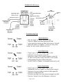
Mac Victor® Power Network
(MVPN)
Installation and Operating Instructions
Mac Victor®
Expand Your Power®
Page 1 of 8
Mac Victor® Power Network (MVPN)
Installation Instructions (Retrofits)
1. Determine which “critical circuit breakers” feed power to the remote receptacles and/or hard wired loads that are required to be
tied into the power isolation and battery backup of the MVPN. This will typically be the POS network receptacles and related
equipment, office computer, telephone system, security system, etc.
2. Remove the panelboard covers for the “critical circuit breakers”. Use an amp probe or other current measuring device to amp
out all the hot conductors connected to the “critical circuit breakers”. The total amp load for the summation of all the “critical circuit
breakers” must be 12 amps or less.
3. Locate a convenient wall location as close to the electrical panels as possible where there is adequate wall space to mount the
MVPN /shelf assembly and the POWERVAR Uninterruptible Power Manager (UPM). A space measuring 20” h x 26” w x 11.0” d is
required for the entire assembly. If the shelf and the POWERVAR UPM are mounted separately from the MVPN they must be
within approximately 4 feet of each other in order for the plug and receptacle cables to connect between these two primary product
components.
4. Attach the MVPN / shelf assembly to the wall using hex head lag screws that are a minimum of 1/4 inch diameter and a
minimum of 1 1/2 inches long. If the assembly cannot be attached to building framing members such as studs, it is the
responsibility of the installer to use anchoring devices that are appropriate for the surface material to which the assembly is being
mounted. Total assembly weight (MVPN, shelf, and UPM) is 70 pounds. Remove the ten screws that hold on the front cover,
remove the cover panel, and set to the side. If mounting the MVPN separately from the shelf and UPM, remove the six screws that
connect the shelf assembly to the power interface enclosure. Mount the MVPN using the 4 mounting holes in the back of the box.
5. Select a 120V, 15 or 20 Amp, single pole, circuit breaker in one of the panelboards to feed power to the MVPN. This may be one
of the “critical circuit breakers” that is currently feeding one of the “critical circuits”. DO NOT use “GROUND FAULT CIRCUIT
INTERRUPT” (GFCI) TYPE BREAKERS to feed power to the MVPN. GFCI type breakers will trip when putting the MVPN
into bypass mode because of the “make before break” feature of the bypass switch.
6. Using EMT conduit, flexible conduit, or 15 amp minimum rated MC cable, run a single circuit (Hot – Black, Neutral – White, and
Ground – Green) to feed power to the MVPN on terminals “L”, “N”, and “G” in the lower, right hand corner of enclosure on terminal
block TB-2. This circuit is considered “dirty power” since it has not been conditioned yet by the POWERVAR UPM and should not
be run in the same conduit as the “clean power” circuits that will feed power to all the “critical circuits”. Conductor size should be 14
AWG minimum.
7. Using EMT conduit, flexible conduit, or 15 amp minimum MC cable, run a single circuit (Hot – Black, Neutral – White, Safety
Ground – Green, and Isolated Ground – Green/yellow stripe) for each of the “critical circuits” from the MVPN to the panelboards.
Conductor size should be 14 AWG minimum. Continuous EMT conduit and / or MC cable (with the outer metal armor or sheath
containing a non-insulated ground wire rated for the return ground path) can perform the safety (equipment) ground function and
eliminate the need for the separate safety ground conductor. In these cases, the green insulated conductor becomes the Isolated
Ground conductor which terminates at the Isolated Ground receptacle ground lug. NOTE: For new installations, run the
“critical circuit” conduits / cables directly to the MVPN enclosure.
8. Terminate each set of conductors to the MVPN on terminals “LD 1 – LD 4”, “N”, “G”, and “IG” on terminal block TB1.
9. Before proceeding to step 10, be sure to communicate with local management that the “critical circuits” will have to be shut off
temporarily to perform the system tie in. Local management may want to power down certain computers and other equipment
before turning off the “critical circuit breakers”.
10. Turn off all the “critical circuit breakers” and verify that the equipment plugged into the “critical circuits” goes off.
11. Remove the hot conductor (black) from the breaker, neutral conductor (white) from the neutral bar, safety ground (green) from
the ground bar, and isolated ground (green/yellow stripe) from the isolated ground bar. Use wire nuts or butt connectors to splice
each set of “critical circuit” conductors to each set of output conductors that terminate to the MVPN.
12. Remove all existing surge strips, filters, and / or UPS devices plugged into the “critical circuit” equipment receptacles.
13. Turn the Transfer Switch on the MVPN to the RIGHT which is the “Bypass” position. Turn on the circuit breaker feeding input
power to the MVPN. Both the “Input” and “Output” pilot lights should be illuminated and all the connected “critical circuit” equipment
should come back on.
Page 2 of 8
(Retrofit Installations - cont.)
14. Plug the POWERVAR UPM into the receptacle located on the right hand side exterior of the MVPN. Plug the cable coming
from the top of the MVPN into one of the receptacles on the back of the POWERVAR UPM.
15. Turn on the POWERVAR UPM by pressing the “on/off” switch (right hand of front panel) and holding for several seconds until
the row of 6 status indicator lights at the bottom of the bezel begins to illuminate. Allow the UPM to go through the self test mode;
which is finished when the green indicator light with the AC power symbol (2nd from left) illuminates continuously and all the others
go off. See the POWERVAR UPM manual if any conditions other than the one described occurs.
16. IMPORTANT NOTE: If the input circuit breaker to the MVPN trips off during the startup of the POWERVAR UPM, it is
typically not a problem with the UPM but with the circuit breaker itself. The circuit breaker should be replaced with one
that is rated for High Magnetic inrush loads. See Page 6 in this manual for more information.
17. Turn the Transfer Switch on the MVPN to the LEFT which is the “Normal” position.
18. Reinstall the MVPN front cover using the ten screws removed in step 4.
19. Advise local management that the installation is complete and all the “Critical Electronic Systems” that are tied in will have
battery backup, power isolation, and surge protection. Show local management the “input” and “output” pilot lights on the MVPN
and how to use the “Bypass” switch in the event of UPM failure or service. See Page 7 in this manual for more information. Also
review POWERVAR UPM operation and provide the operation manual / POWERVAR “e library” CD to local management.
New Installations
For all new installations, follow the previous instructions except for Step 9 through Step 11. In new installations, critical
equipment circuits can be piped directly into the MVPN and connected directly to the MVPN terminal blocks.
Warranty Information
Mac Victor Power warrants the Mac Victor Power Network (known hereafter as the "product") to be free from defects
in material and workmanship for a period of five years from the date of shipment. POWERVAR warrants its Security
One UPM or Uninterruptible Power Manager series (known hereafter as “the product”) to be free from defects in
material and workmanship for a period of five years (two years on batteries) from the date of shipment. The product
will be repaired or replaced at no charge during this warranty period. There are no other warranties, expressed or
implied, of merchantability, fitness for a particular purpose, performance, condition, capacity, or otherwise. Neither
Mac Victor Power nor POWERVAR is liable for incidental or consequential damages, monetary loss, loss of sales, or
loss of business resulting from the failure or malfunction of the product. Warranty is void on product that is misused,
misapplied, abused, altered by unauthorized personnel or where evidence of tampering exists. The foregoing
constitutes the sole and exclusive remedy of the purchaser and is in lieu of all other warranties. No greater degree of
liability is imposed on Mac Victor Power or POWERVAR, Inc.
Technical and Service Assistance
Technical and service assistance is available in North America between the hours of 8:00 a.m. and 5:00 p.m. Central
Time by calling 800-369-7179 (in Illinois, call (847) 596-7000.
Customer Service
For service, obtain the model number, part number, and serial number from the rear panel data plate. Then contact
either Mac Victor Power or POWERVAR via phone or web to obtain a Return Material Authorization (RMA) number.
This number must be marked on the shipping container and packing slip of the unit being returned. The original
shipping container should be used if available. Additional charges will apply for repair of damages caused by improper
packing of the returned unit. Unauthorized return shipments will be refused. Units for repair must be shipped prepaid
to the return address provided with the Return Material Authorization.
Page 3 of 8
Description of Operation
• 120 VAC, 1φ input power (15A / 20A circuit) supplied to MVPN
• Input power status light is illuminated
• Power routed within MVPN to Normal / Bypass transfer switch
• In Normal mode
• Power routed from Normal/Bypass switch to the POWERVAR
UPM
• POWERVAR UPM conditions power and provides battery
backup
• 120 VAC, 1φ power conditioned UPM output is wired back to
the MVPN
• Output power status pilot light is illuminated
• MVPN provides power conditioned, battery backup source to
dedicated, hardwired receptacles and equipment
• In Bypass Mode
• Power is routed from Normal / Bypass switch directly to
dedicated receptacles and equipment, bypassing the UPM
• Output power status pilot light remains illuminated and does
not flicker during the transfer (make before break)
• Remote Power Off (RPO) Switch - 15 amp “push / pull” type
mushroom switch wired through the normally closed (N/C) contacts
• When RPO is pushed, output power from the UPM is
disconnected from the dedicated receptacles / equipment
• When the RPO is pulled, output power from the UPM is
reconnected to the dedicated receptacles / equipment
Theory of Operation
Isolated ground (IG) receptacles (identified by their orange color or
an orange triangle) are used with sensitive electronic systems to
provide a separate ground reference point from the safety or
equipment ground required to protect personnel from fault currents
that might arise out of short circuit in the load.
Typically, the IG conductor must be run back to the electrical service
entrance grounding terminal of the facility, which can result in
common mode voltage arising from induced noise voltages from
other parallel conductors in the same raceway and panelboards.
The National Electrical Code (NEC) allows for an alternative method
of eliminating common mode noise disturbances through the use of
a “separately derived system.” The POWERVAR UPM constitutes a
separately derived system because its internal, low impedance,
isolation transformer has its output neutral bonded to ground.
The MVPN provides the necessary power interface between the
output of the UPM and the remote, hard wired receptacles. There
are other practical operational and maintenance features as well.
MVPN Specifications
• Battery backup time - 6 min. full load / 20 min. @ half load
• Requires one (1) 120 VAC, 1φ input (15 or 20 amps)
• Requires one (1) POWERVAR model ABCE1440-11
• Maximum load of 12 amps @ 120 VAC (1440 VA)
• Pilot light status indicators for input / output power
• Make before break bypass / transfer switch
Mac Victor Power Network Benefits
• Convenience - Space is frequently a valuable commodity in the
small store format. The MVPN permits all critical equipment within
the small store environment to receive conditioned, uninterruptible
power without the need for distributed UPS or power conditioners.
• Assures that all connected loads are on the same phase / circuit
• Provides for true isolated power from other noise sources
• Easier maintenance - the bypass / transfer switch allows for
removal of the UPM for maintenance or service without disrupting
power to the critical electronic loads
• Input and output power status indicators make diagnostics easy
• Optional RPO (REMOTE POWER OFF) provides for remote
disconnection of the UPM
Page 4 of 8
Where required by
local Electrical AHJ
Page 5 of 8
NUISANCE TRIPPING OF INPUT CIRCUIT BREAKER
Some reports from field installations indicate that the 15 or 20 amp, single pole circuit breaker feeding main power to
the Mac Victor® Power Network (MVPN) will sometimes trip off upon startup of the POWERVAR UPM. In all cases,
factory testing has indicated that this problem is not associated with defects in the POWERVAR UPM. POWERVAR’s
investigation has revealed that when the MVPN is located in close proximity to the panelboard (approximately 10
feet), the current inrush caused by the initial start up of the UPM can trip the panelboard branch circuit breaker due to
high magnetic inrush even when it is not overloaded. The solution to this problem is to replace the circuit breaker with
one that can withstand the high magnetic inrush of the UPM startup.
TB-2
Listed below are the approved circuit breakers for various panelboard manufacturers that are designed to withstand
this high magnetic inrush.
Panelboard
Manufacturer:
Part Numbers:
Square D
QO-115-HM or QO-120-HM (snap on)
QOB-115-HM or QOB-120-HM (bolt on)
GE
THQL1115HID or THQL1120HID (snap on)
THQB1115HID or THQB1120HID (bolt on)
Cutler Hammer
HQP1015D or HQP1020D (snap on)
BAB1015D or BAB1020D (bolt on)
Page 6 of 8
POWERVAR UPM Details
UPM
Circuit Breaker
(Each LED = 20%)
(Each LED = 20%)
Cooling
Fan
(Push to Start)
Serial Comm Port
Input Power from
Mac Victor
receptacle
Input Power
from
Mac Victor
receptacle
Output Power
receptacles to
Mac Victor
plug cable
Output Power to
Mac Victor
plug cable
Troubleshooting Tips
Normal Operation
“ON” “ON”
* Both the “Input” & “Output” lights are “ON”
* Switch to “Bypass” only when replacing the UPM
* After replacing & starting up UPM, Switch back to “Normal”
* When the Switch is in “Bypass”, if there is a utility power
outage, the entire power network will go off.
Loss of Input Power
“OFF” “ON”
*
*
*
*
*
*
“Input” light is “OFF” and “Output” light is “ON”
Indication of a utility power outage OR
Indication of input circuit breaker tripped or turned off
If there is not a power outage, check the circuit breaker
UPM is keeping the power network energized
Do NOT Switch to “Bypass” or the power network will go off
Loss of Output Power
“ON” “OFF”
*
*
*
*
*
*
“Input” light is “ON” and “Output” light is “OFF”
Immediately Switch to “Bypass” to restore power network
Indication of circuit breaker on back of UPM tripped OR
Indication of UPM failure OR
Indication that Mac Victor plug cable not plugged into UPM
Switch to “Normal” after the UPM power is restored
Page 7 of 8
Mac Victor®
Expand Your Power®
Mac Victor Power
Fredericksburg, VA
Phone: (540) 220-8116
Fax: (540) 242-7004
email: [email protected]
www.MacVictor.com
SM523 – 06/2005 - © 2005 POWERVAR, Inc.
Page 8 of 8