1
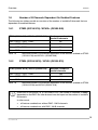
Siemens
Common Gateway
1 Common Gateway (CG). . . . . . . . . . . . . . . . . . . . . . . . . . . . . . . . . . . . . . . . . . . . . . . . . . . 5
1.1 Gateways . . . . . . . . . . . . . . . . . . . . . . . . . . . . . . . . . . . . . . . . . . . . . . . . . . . . . . . . . . . . . 5
1.2 Hardware and Loadware NCUI. . . . . . . . . . . . . . . . . . . . . . . . . . . . . . . . . . . . . . . . . . . . . 6
1.3 General Information . . . . . . . . . . . . . . . . . . . . . . . . . . . . . . . . . . . . . . . . . . . . . . . . . . . . . 6
1.4 Hardware and Loadware HG3500 V4. . . . . . . . . . . . . . . . . . . . . . . . . . . . . . . . . . . . . . . . 7
1.5 General Information . . . . . . . . . . . . . . . . . . . . . . . . . . . . . . . . . . . . . . . . . . . . . . . . . . . . . 7
1.6 Restrictions . . . . . . . . . . . . . . . . . . . . . . . . . . . . . . . . . . . . . . . . . . . . . . . . . . . . . . . . . . . . 8
1.7 Impact On Existing Functions . . . . . . . . . . . . . . . . . . . . . . . . . . . . . . . . . . . . . . . . . . . . . . 8
1.8 Number of B Channels Dependent On Enabled Features . . . . . . . . . . . . . . . . . . . . . . . . 9
1.8.1 STMI2 (Q2316-X10) / NCUI2+ (Q2305-X40) . . . . . . . . . . . . . . . . . . . . . . . . . . . . . . . 9
1.8.2 STMI4 (Q2324-X510) / NCUI4 (Q2324-X10) . . . . . . . . . . . . . . . . . . . . . . . . . . . . . . . 9
2 Architecture and System Requirements . . . . . . . . . . . . . . . . . . . . . . . . . . . . . . . . . . . . 11
2.1 Prerequisites . . . . . . . . . . . . . . . . . . . . . . . . . . . . . . . . . . . . . . . . . . . . . . . . . . . . . . . . . . 11
2.2 Power Requirements . . . . . . . . . . . . . . . . . . . . . . . . . . . . . . . . . . . . . . . . . . . . . . . . . . . 11
2.3 Network Requirements . . . . . . . . . . . . . . . . . . . . . . . . . . . . . . . . . . . . . . . . . . . . . . . . . . 11
2.4 Basic Configuration Requirements . . . . . . . . . . . . . . . . . . . . . . . . . . . . . . . . . . . . . . . . . 12
2.5 Bandwidth Requirements . . . . . . . . . . . . . . . . . . . . . . . . . . . . . . . . . . . . . . . . . . . . . . . . 13
2.5.1 Encoding . . . . . . . . . . . . . . . . . . . . . . . . . . . . . . . . . . . . . . . . . . . . . . . . . . . . . . . . . 13
2.5.2 Sampling Time . . . . . . . . . . . . . . . . . . . . . . . . . . . . . . . . . . . . . . . . . . . . . . . . . . . . . 13
2.5.3 IP Overhead . . . . . . . . . . . . . . . . . . . . . . . . . . . . . . . . . . . . . . . . . . . . . . . . . . . . . . . 14
2.5.4 Required Bandwidth per Connection . . . . . . . . . . . . . . . . . . . . . . . . . . . . . . . . . . . . 14
2.5.5 Voice Activity Detection (VAD) . . . . . . . . . . . . . . . . . . . . . . . . . . . . . . . . . . . . . . . . . 15
2.5.6 DMC Considerations . . . . . . . . . . . . . . . . . . . . . . . . . . . . . . . . . . . . . . . . . . . . . . . . 16
2.6 Traffic Considerations . . . . . . . . . . . . . . . . . . . . . . . . . . . . . . . . . . . . . . . . . . . . . . . . . . . 17
3 Capacities and Limitations . . . . . . . . . . . . . . . . . . . . . . . . . . . . . . . . . . . . . . . . . . . . . . . 19
EN2409EN00EN_0001
© 2007 Siemens AG
1
Siemens
4 Features . . . . . . . . . . . . . . . . . . . . . . . . . . . . . . . . . . . . . . . . . . . . . . . . . . . . . . . . . . . . . .
4.1 Gateway Functionality . . . . . . . . . . . . . . . . . . . . . . . . . . . . . . . . . . . . . . . . . . . . . . . . . .
4.2 Resource Management . . . . . . . . . . . . . . . . . . . . . . . . . . . . . . . . . . . . . . . . . . . . . . . . .
4.3 Direct Media Connections . . . . . . . . . . . . . . . . . . . . . . . . . . . . . . . . . . . . . . . . . . . . . . .
4.4 Mobility . . . . . . . . . . . . . . . . . . . . . . . . . . . . . . . . . . . . . . . . . . . . . . . . . . . . . . . . . . . . . .
4.5 Secondary Clients . . . . . . . . . . . . . . . . . . . . . . . . . . . . . . . . . . . . . . . . . . . . . . . . . . . . .
4.6 Standby Gateways. . . . . . . . . . . . . . . . . . . . . . . . . . . . . . . . . . . . . . . . . . . . . . . . . . . . .
4.7 Secondary Gateways . . . . . . . . . . . . . . . . . . . . . . . . . . . . . . . . . . . . . . . . . . . . . . . . . . .
4.8 Voice Compression . . . . . . . . . . . . . . . . . . . . . . . . . . . . . . . . . . . . . . . . . . . . . . . . . . . .
4.9 Voice Activity Detection (VAD). . . . . . . . . . . . . . . . . . . . . . . . . . . . . . . . . . . . . . . . . . . .
4.10 Comfort Noise Generation (CNG) . . . . . . . . . . . . . . . . . . . . . . . . . . . . . . . . . . . . . . . .
4.11 Echo Cancellation . . . . . . . . . . . . . . . . . . . . . . . . . . . . . . . . . . . . . . . . . . . . . . . . . . . .
4.12 QOS Support . . . . . . . . . . . . . . . . . . . . . . . . . . . . . . . . . . . . . . . . . . . . . . . . . . . . . . . .
4.12.1 Real Time Port Monitoring. . . . . . . . . . . . . . . . . . . . . . . . . . . . . . . . . . . . . . . . . . .
4.12.2 Signaling Connection Monitoring. . . . . . . . . . . . . . . . . . . . . . . . . . . . . . . . . . . . . .
4.12.3 Supports the Feature QDC . . . . . . . . . . . . . . . . . . . . . . . . . . . . . . . . . . . . . . . . . .
4.13 Physical Interfaces. . . . . . . . . . . . . . . . . . . . . . . . . . . . . . . . . . . . . . . . . . . . . . . . . . . .
4.14 Security . . . . . . . . . . . . . . . . . . . . . . . . . . . . . . . . . . . . . . . . . . . . . . . . . . . . . . . . . . . .
4.14.1 Access for Administration . . . . . . . . . . . . . . . . . . . . . . . . . . . . . . . . . . . . . . . . . . .
4.14.2 Access to SNMP . . . . . . . . . . . . . . . . . . . . . . . . . . . . . . . . . . . . . . . . . . . . . . . . . .
4.14.3 Security in CorNetTC Registration . . . . . . . . . . . . . . . . . . . . . . . . . . . . . . . . . . . .
4.14.4 H.235 Security. . . . . . . . . . . . . . . . . . . . . . . . . . . . . . . . . . . . . . . . . . . . . . . . . . . .
4.15 Reliability . . . . . . . . . . . . . . . . . . . . . . . . . . . . . . . . . . . . . . . . . . . . . . . . . . . . . . . . . . .
4.15.1 Duplex System Support. . . . . . . . . . . . . . . . . . . . . . . . . . . . . . . . . . . . . . . . . . . . .
4.15.2 Survivability Options . . . . . . . . . . . . . . . . . . . . . . . . . . . . . . . . . . . . . . . . . . . . . . .
4.15.2.1 Line Gateway Redundancy. . . . . . . . . . . . . . . . . . . . . . . . . . . . . . . . . . . . . . .
4.15.2.2 Standby Gateways . . . . . . . . . . . . . . . . . . . . . . . . . . . . . . . . . . . . . . . . . . . . .
4.15.2.3 Secondary Gateways . . . . . . . . . . . . . . . . . . . . . . . . . . . . . . . . . . . . . . . . . . .
21
21
21
21
22
22
23
23
23
23
24
24
24
24
25
25
25
26
26
27
27
27
27
27
27
27
28
29
5 General Information on How to Configure a HG 3500 V4 Common Gateway . . . . . .
5.1 General Information . . . . . . . . . . . . . . . . . . . . . . . . . . . . . . . . . . . . . . . . . . . . . . . . . . . .
5.2 Rules . . . . . . . . . . . . . . . . . . . . . . . . . . . . . . . . . . . . . . . . . . . . . . . . . . . . . . . . . . . . . . .
5.3 Restrictions . . . . . . . . . . . . . . . . . . . . . . . . . . . . . . . . . . . . . . . . . . . . . . . . . . . . . . . . . .
31
31
32
34
6 Multiple Feature Support Configuration at the Common Gateway (Example) . . . . .
6.1 Configuring Functional Blocks with the AMO BFDAT . . . . . . . . . . . . . . . . . . . . . . . . . .
6.2 Configuring the Common Gateway Board with the AMO BCSU . . . . . . . . . . . . . . . . . .
6.3 Configuration of a IPDA . . . . . . . . . . . . . . . . . . . . . . . . . . . . . . . . . . . . . . . . . . . . . . . . .
6.4 Configuration of a HFA phone . . . . . . . . . . . . . . . . . . . . . . . . . . . . . . . . . . . . . . . . . . . .
6.5 Configuring SIP Trunking. . . . . . . . . . . . . . . . . . . . . . . . . . . . . . . . . . . . . . . . . . . . . . . .
6.6 Completed and Uncompleted Functional Block . . . . . . . . . . . . . . . . . . . . . . . . . . . . . . .
6.6.1 Uncompleted functional block . . . . . . . . . . . . . . . . . . . . . . . . . . . . . . . . . . . . . . . . .
6.6.2 Completed configuration block . . . . . . . . . . . . . . . . . . . . . . . . . . . . . . . . . . . . . . . .
35
35
36
36
37
37
37
37
38
7 Command Line Interface CLI at HG 3500 . . . . . . . . . . . . . . . . . . . . . . . . . . . . . . . . . . . 39
7.1 General Information . . . . . . . . . . . . . . . . . . . . . . . . . . . . . . . . . . . . . . . . . . . . . . . . . . . . 39
2
EN2409EN00EN_0001
© 2007 Siemens AG
Siemens
7.2
7.3
7.4
7.5
7.6
7.7
7.8
General Operations. . . . . . . . . . . . . . . . . . . . . . . . . . . . . . . . . . . . . . . . . . . . . . . . . . . . . 39
Access control. . . . . . . . . . . . . . . . . . . . . . . . . . . . . . . . . . . . . . . . . . . . . . . . . . . . . . . . . 40
Gateway Setup . . . . . . . . . . . . . . . . . . . . . . . . . . . . . . . . . . . . . . . . . . . . . . . . . . . . . . . . 40
Image/File Handling . . . . . . . . . . . . . . . . . . . . . . . . . . . . . . . . . . . . . . . . . . . . . . . . . . . . 40
Maintenance . . . . . . . . . . . . . . . . . . . . . . . . . . . . . . . . . . . . . . . . . . . . . . . . . . . . . . . . . . 41
SSL for WBM . . . . . . . . . . . . . . . . . . . . . . . . . . . . . . . . . . . . . . . . . . . . . . . . . . . . . . . . . 42
Changing the Login and Password for CLI . . . . . . . . . . . . . . . . . . . . . . . . . . . . . . . . . . . 43
8 Technical Data for HG 3500/3575 . . . . . . . . . . . . . . . . . . . . . . . . . . . . . . . . . . . . . . . . . . 45
9 Questions and Exercises to the Common Gateway . . . . . . . . . . . . . . . . . . . . . . . . . . . 49
9.1 Which boards can be used in a HiPath 4000 V4 as a HG3500? . . . . . . . . . . . . . . . . . . 49
9.2 What must be considered for a setup of function blocks with the AMO BFDAT? . . . . . . 49
9.3 Which restriction exists if the HG3500 is working with the function HG3550? . . . . . . . . 49
9.4 Which function ID must be used with the AMO BCSU for a setup of a Common Gateway
board? . . . . . . . . . . . . . . . . . . . . . . . . . . . . . . . . . . . . . . . . . . . . . . . . . . . . . . . . . . . . . . . 49
9.5 Which task the AMO STMIB has? . . . . . . . . . . . . . . . . . . . . . . . . . . . . . . . . . . . . . . . . . 49
9.6 Which AMO for the administration of HG3530 doesn’t exist anymore in the HiPath 4000
V4? . . . . . . . . . . . . . . . . . . . . . . . . . . . . . . . . . . . . . . . . . . . . . . . . . . . . . . . . . . . . . . . . . 49
9.7 Check the predefined profiles (SFM and MFM) for the Common Gateway. . . . . . . . . . . 50
9.8 Create a Common Gateway with the HG3530 feature, 60 B channels and 120 subsribers.
50
9.9 Create a Common Gateway in mixed modus. . . . . . . . . . . . . . . . . . . . . . . . . . . . . . . . . 50
10 Solutions. . . . . . . . . . . . . . . . . . . . . . . . . . . . . . . . . . . . . . . . . . . . . . . . . . . . . . . . . . . . . 51
10.0.1 Which boards can be used in a HiPath 4000 V4 as an HG3500? . . . . . . . . . . . . . 51
10.0.2 What must be considered for a setup of function blocks with the AMO BFDAT? . 51
10.1 Which restriction exists if the HG3500 is working with the function HG3550? . . . . . . . 51
10.2 Which function ID must be used with the AMO BCSU for a setup of a Common Gateway
board? . . . . . . . . . . . . . . . . . . . . . . . . . . . . . . . . . . . . . . . . . . . . . . . . . . . . . . . . . . . . . . . 51
10.3 Which task the AMO STMIB has? . . . . . . . . . . . . . . . . . . . . . . . . . . . . . . . . . . . . . . . . 51
10.4 Which AMO for the administration of HG3530 doesn’t exist anymore in the HiPath 4000
V4? . . . . . . . . . . . . . . . . . . . . . . . . . . . . . . . . . . . . . . . . . . . . . . . . . . . . . . . . . . . . . . . . . 51
10.5 Check the predefined profiles (SFM and MFM) for the Common Gateway. . . . . . . . . . 52
10.6 Create a Common Gateway with the HG3530 feature, 60 B channels and 120 subsribers.
52
10.7 Create a Common Gateway in mixed modus. . . . . . . . . . . . . . . . . . . . . . . . . . . . . . . . 53
EN2409EN00EN_0001
© 2007 Siemens AG
3
Siemens
4
EN2409EN00EN_0001
© 2007 Siemens AG
Overview
1
Siemens
Common Gateway (CG)
The Common Gateway combines the different IP Gateway functions (HG3530, HG3550,
HG3540 and HG3570 in one SW core.
Each sub-function (e.g. HFA or SIP) can be configured on one single HG3500 board,
The CGW SW can run on existing STMIV2 cards or on the „new“ STMIV4 card.
1.1
Gateways
The following gateways are supported in HiPath 4000 V4:
●
HG 3575 V4
with the boards
●
–
NCUI2+ (Q2305-X35 and Q2305-X40)
–
NCUI4 (Q2324-X and Q2324-X10)
HG 3550 V1 (STMI (Q2303-X10) and (Q2303-X20))
>
●
For IP trunking only.
HG 3500 V4 (Common Gateway)
with the boards
–
STMI2 (Q2316-X and Q2316-X10)
–
STMI4 (Q2324-X500 and Q2324-X510)
Difference NCUI2 and NCUI2+:
The NCUI2+ has more RAM (128 MB instead of 64 MB) and the FEPROM more memory capacity (32 MB instead of 16 MB)
Difference between NCUI2+ and NCUI4:
The NCUI4 (Q2324-X10) has 5 DSPs ,the NCUI+ (Q2305-X40) only 4.
The NCUI4 has faster DSPs (720 MHz instead of 500 MHz) and more memory (32 MB instead
of 16 MB).
EN4442EN00EN_0002
© 2007 Siemens AG
5
Overview
Siemens
>
1.2
The NCUI2 can be used for the migration!
Hardware and Loadware NCUI
New loadware (PZKNCI40) is available for the boards NCUI2+ and NCUI4 in HiPath 4000 V4
and later versions.
Board type
Part number
B channels
NCUI2+
Q2305-X35
60 B channels (2 DSPs)
NCUI2+
Q2305-X40
120 B channels (4 DSPs)
NCUI4
Q2324-X
60 B channels (2 DSPs)
NCUI4
Q2324-X10
120 B channels (5 DSPs)
Table 1-1
Supported NCUI boards
Board type Loadware
NCUI2+
PZKNCI40
NCUI4
PZKNCI40
Table 1-2
1.3
6
Restricted B channels
Full feature scope
x
Not possible
x
Boards, loadware, B channels and feature scope
General Information
●
HG 3575 IPDA will be upgraded to HG 3550 architecture. Basic functionality will remain
the same. This hub serves as a basis for integrating other possible features.
●
In contrast to HG 3500, there is no standby concept for HG 3575.
●
The NCUI board is still configured with the AMO STMIB.
EN4442EN00EN_0002
© 2007 Siemens AG
Overview
1.4
Siemens
Hardware and Loadware HG3500 V4
Until HiPath 4000 V3.0 was released, each feature had separate loadware. This loadware determined the function of the gateway (HG 3530, HG 3540/3550, HG 3570). In HiPath 4000 V4
and later, the various types of loadware are consolidated into a common loadware for STMI2
and STMI4. With this loadware all features are available on the board.
Board
Part number
B channels
STMI2
Q2316-X
60 B channels (2 DSPs (30 B channels per DSP))
STMI2
Q2316-X10
120 B channels (4 DSPs (30 B channels per DSP))
STMI4
Q2324-X500
60 B channels (2 DSPs (30 B channels per DSP))
STMI4
Q2324-X510
120 B channels (5 DSPs (30 B channels per DSP))
Table 1-3
Supported STMI boards
Board
Loadware
Restricted B channels
Full feature scope
STMI2
PZKSTI40
x
Not possible
STMI4
PZKSTI40
STMI1
HG 3550 V1.0 (only H323 trunking)
Table 1-4
1.5
x
Boards, loadware, B channels and feature scope
General Information
●
The HiPath 4000 V4 common gateway HG 3500 consolidates existing VoIP gateways into
a single gateway.
●
This forms a common architecture based on HG 3550 V2.0 for HiPath 4000 V3.0.
●
All functions provided by the HG 3530, HG 3540, HG 3550 and HG 3570 gateways, including redundancy and load sharing, are retained.
●
The HiPath 4000 V4 system software has been enhanced to support the “mixed“ common
gateway. This means that all sub features (trunking, VoIP subscriber, IPDA and WAML)
can be used in parallel on a board.
>
●
Restriction: Only one trunking protocol may be configured for each board. There
are no restrictions on interworking with other functions.
The HiPath Feature Access (HFA) standby concept will be made available for other functions.
EN4442EN00EN_0002
© 2007 Siemens AG
7
Overview
Siemens
1.6
Restrictions
CQR Viewer
The CQR Viewer application is only supported for HFA (FUNCTION=HG3530) and IPDA
(FUNCTION=HG3570), not for trunking (FUNCTION=HG3550).
1.7
8
Impact On Existing Functions
●
Impact on DLS: None.
●
Impact on terminals/clients: None. All HiPath 4000 V3.0 IP telephones are supported.
OpenStage telephones are also supported.
●
Impact on ACL: None.
●
Impact on CDR: None.
●
Impact on analysis options: With the common gateway, all sub features now include comprehensive HG 3550 analysis options.
●
Impact on encryption: The common gateway alone no longer supports the HiPath 4000
V3.0 encryption feature. This function will be available again when signaling and payload
encryption are released.
●
Impact on HFA mobility: None. This feature remains unchanged and continues to be supported.
●
Impact on the standby board concept: Based on the HiPath 4000 V3.0 HFA standby concept in HG 3530, the functional scope of the STMI board is expanded to match that of the
HG 3500.
EN4442EN00EN_0002
© 2007 Siemens AG
Overview
Siemens
1.8
Number of B Channels Dependent On Enabled Features
The following two tables provide an overview of the number of available B channels that are
dependent on enabled features.
1.8.1
STMI2 (Q2316-X10) / NCUI2+ (Q2305-X40)
STMI2 (Q2316-X10) / NCUI2+ (Q2305-X40)
Maximum number of
parallel B channels
Plain + SRTP + QDC + DMC
60
Plain + SRTP + DMC
60
Plain + QDC + DMC
85
Plain + DMC
90
Table 1-5
Maximum number of B channels dependent on the features enabled on STMI2
(Q2316-X10) and NCUI2+ (Q2305-X40)
1.8.2
STMI4 (Q2324-X510) / NCUI4 (Q2324-X10)
STMI4 (Q2324-X510) / NCUI4 (Q2324-X10)
Maximum number of
parallel channels
Plain + SRTP + QDC + DMC
100
Plain + SRTP+ QDC
120
Plain + DMC
100
Table 1-6
Maximum number of B channels dependent on the features enabled on STMI4
(Q2324-X510) and NCUI4 (Q2324-X10)
>
In the case of V4 boards (i.e. STMI4 and NCUI4), the number of channels is solely
dependent on the DMC. No other features have an impact on the number of available
B channels.
In other words,
●
all feature combinations without DMC: 120 B channels
●
all feature combinations with DMC: 100 B channels
EN4442EN00EN_0002
© 2007 Siemens AG
9
Siemens
10
Overview
EN4442EN00EN_0002
© 2007 Siemens AG
Architecture and System Requirements
2
Architecture and System Requirements
2.1
Prerequisites
Siemens
Prior to installing IP line gateways at a customer site a network assessment is required that will
determine whether the customer’s IP network is capable of supporting IP phones. This network
assessment will analyze the IP network and determine parameters like jitter, packet loss,
available bandwidth, supported QOS mechanisms and assess overall VoIP readiness.
2.2
Power Requirements
The HG 3500 line gateway is a standard HiPath 4000 card that plugs into standard HiPath 4000
enclosures (AP 3300 and AP 3700 Access Points). However, HG 3500 cards require more than
average power due to components with high power demands (DSPs). This limits the total
number of HG 3500 cards to a maximum of 6 cards per AP 3700 IP (9 slot), 10 cards per AP
3700 (13 slot) and 5 cards per AP 3300.
2.3
Network Requirements
The HG 3500 place high demands on the network via which it is coupled to its IP endpoints.
Just like Voice-over-IP data streams are sensitive to packet runtime, runtime variance (jitter)
and packet loss.
The availability and reliability of a HG 3500 system depends heavily on the quality of the IP
network used.
Therefore, the network must be examined prior to installation with regard to its suitability for
VoIP for the use of HiPath 4000 HG 3500. More details can be found in the HiPath Network
Analysis Guide.
All HiPath 4000 components must be connected to their own ports on Layer 2 switches.
Using hubs together with HiPath 4000 can cause problems. For this reason, they are not
permitted for use in corresponding VoIP scenarios. If hubs are available, they should be
replaced with a switch.
In order to achieve a high Quality of Service (voice quality/real time behavior of signaling), the
support of IEEE 802.1 p/q VLAN Tagging and IETF RFC 2474 DiffServ is recommended.
>
Note
If an access point is connected over Wide Area Networks in which the available
bandwidth is extremely restricted, the control information (signaling) and voice
data (payload) for access points must be given priority over other services.
EN4442EN00EN_0002
© 2007 Siemens AG
11
Architecture and System Requirements
Siemens
Frequently, only explicitly familiar TCP/IP or UDP/IP port numbers are supported in the
customer LAN for security reasons. All others are then blocked in such cases. Precisely which
port numbers must be supported for the HiPath HG 3500 component in the network is
described in Section 16.1, “Gateway Port Allocation”.
2.4
Basic Configuration Requirements
For a HG 3500 line gateway to be operational on a live IP network the following parameters
have to be configured.
Every HG 3500 requires configuration data which must be coordinated with the network
administration of the customer, documented and configured precisely as agreed.
The following data must be specified for every new node in the customer LAN:
●
IP address of the node
●
Netmask for the network in which the new node is added
●
Default router via which the other networks can be reached
Furthermore, the way in which Quality of Service is supported must be clarified for all networks
in which HiPath 4000 components are installed. As HiPath 4000 supports IP distributed
architecture processes for controlling the Quality of Service in a network on various protocol
layers, the following must be clarified:
●
Is IEEE 802.1 p/q VLAN Tagging (Layer 2) supported?
To this end, it is crucial that all network components with which a HiPath 4000 component
communicates must support the standard and be configured accordingly. If the network
contains nodes (particularly switches and routers) which do not support IEEE 802.1 p/q,
VLAN tagging must remain deactivated. The traffic type is assigned a fixed priority value.
●
If DiffServ pursuant to RFC 2474 is supported, which CodePoints can be utilized?
In the HiPath 4000 components, TOS bytes must be set to partially differing values for the
following traffic types. The default values assume DiffServ support on the part of the
network and realize the Quality of Service strategy of Siemens AG.
12
EN4442EN00EN_0002
© 2007 Siemens AG
Architecture and System Requirements
>
Siemens
Note
The TOS byte can be read in a number of different ways:
●
Two 3-bit values for precedence and priority
●
One 6-bit value as a combination of both 3-bit values (DiffServ CP)
●
The entire TOS byte including two fill bits
For IPDA, the entire TOS byte is specified. The two least significant bits are always
set to zero.
See Section 8.1, “Key Words”.
On the HG 3500 these parameters are set by using standard switch administration.
2.5
Bandwidth Requirements
The actual bandwidth per active payload connection depends on the selected encoding
algorithm and the specified sampling time.
2.5.1
Encoding
G.711, G.723 or G.729 encoding can be selected.
●
G.711 encoding generates a net data rate of 64 Kbps,
●
G.723 compresses to 6.4/5.3Kpbs and
●
G.729 compresses to 8Kpbs (see Table 2-1 IP Overhead and BW per Connection for actual
data rates).
Wideband codecs according to G.722 are supported between optiPoint 410 IP phones. The
required bandwidth is the same as for G.711. Note that the gateway itself does not terminate
G.722 voice payload.
>
Note that there is virtually no delay introduced in generating G.711 encoding from
TDM voice packets (Algorithmic Delay = 0 ms).
2.5.2
Sampling Time
Voice needs to be digitized before it can be assembled into IP packets.
EN4442EN00EN_0002
© 2007 Siemens AG
13
Architecture and System Requirements
Siemens
For telephony applications, voice is sampled every 125 μs at 8bits. It would not make sense to
package each individual 8 bit sample into an IP packet. Instead, for G.711 encoding at least
240 8 bit samples are combined into an IP packet.
It takes 30 ms to acquire 240 voice samples.
The Sampling Time is defined as the time it takes to sample a specified number of voice
samples that are sent out in one IP packet.
It is obvious that the longer the sampling time, the smaller the IP overhead gets. Thus, in order
to minimize bandwidth, the sampling time will have to be increased.
However, increasing the sampling time will increase the overall delay!
>
Important
There is always a tradeoff between minimizing the delay versus minimizing the
required bandwidth.
For IP line gateways the sampling time can be set between 10 ms and 90 ms depending on
codec type.
2.5.3
IP Overhead
The IP overhead includes the Real Time Protocol (RTP), User Datagram Protocol (UDP) and
IP headers as well as the Ethernet framing and additional octets for QOS Tagging.
A typical IP overhead value for G.711 is 30% (see Table 2-1 IP Overhead and BW per
Connection for more details).
2.5.4
Required Bandwidth per Connection
The following table shows the required IP bandwidth and IP overhead per voice connection as
a function of Sampling Time and encoding:
Encoding
Sampling Time
IP Overhead
BW per Connection
G.711
10ms
88%
120.0 Kbps
20ms
44%
92.0 Kbps
30ms
29%
82.7 Kbps
40ms
22%
78.0 Kbps
50ms
18%
75.2 Kbps
Table 2-1
14
IP Overhead and BW per Connection
EN4442EN00EN_0002
© 2007 Siemens AG
Architecture and System Requirements
Encoding
G.729A
G.723 (6.4)
Table 2-1
Siemens
Sampling Time
IP Overhead
BW per Connection
60ms
15%
73.3 Kbps
20ms
350%
36.0 Kbps
40ms
175%
22.0 Kbps
60ms
117%
17.3 Kbps
30ms
291%
25.1 Kbps
60ms
146%
15.7 Kbps
90ms
97.2%
12.6 Kbps
IP Overhead and BW per Connection
Note that the bandwidth calculation is based on 70 bytes of overhead: RTP (12 bytes), UDP (8
bytes), IP (20 bytes), 802.1Q VLAN Tagging (4 Bytes), MAC (incl. Preamble, FCS, 26 Bytes).
>
Important
Bandwidth requirements assume Full Duplex operation!
When running Half Duplex, twice the bandwidth is required.
2.5.5
Voice Activity Detection (VAD)
Voice activity detection conserves bandwidth in the IP network during pauses in speech and
can further reduce the required network bandwidth from 50% to 75% (see Section 6.9, “Voice
Activity Detection (VAD)” for more details).
Figure 2-1
EN4442EN00EN_0002
© 2007 Siemens AG
VoIP Bandwidth Reduction Sequence
15
Architecture and System Requirements
Siemens
2.5.6
DMC Considerations
Whenever a DMC connection is established, a “Master Connection” is setup as well.
The master connection is following the same path as the signaling through all the gateways
between to IP clients.
The master connection ensures that the necessary resources are always available whenever
a feature is invoked that results in a multi party call (e.g. conference). There is also no delay
for invoking these types of features because the connection is already setup.
However, there are drawbacks to the master connection concept as well:
●
Additional bandwidth is required for sustaining the master connection
●
Depending on the configuration significant delays and multiple hops can occur between IP
clients when voice payload is using the master connection. Especially when IP end points
are located on different IP Access Points on IP connected systems, delays may increase
beyond acceptable levels.
In Figure 2-2 DMC and Master Connection the DMC and Master Connection is shown between
two IP networked HiPath 4000 systems for a call between two IP clients (one on each system).
Figure 2-2
DMC and Master Connection
Enabling VAD will reduce the required bandwidth on the master connection to negligible levels.
Note that delays for each TDM to IP conversion accumulate. In the example above the master
connection goes through 3 hops which will result in approximately 200ms end to end delay
assuming G.711 encoding with 30ms sampling time and a high quality network (20ms delay).
The DMC connection goes only through one hop resulting in an end to end delay of about
80ms.
16
EN4442EN00EN_0002
© 2007 Siemens AG
Architecture and System Requirements
2.6
Siemens
Traffic Considerations
From a trafficking point of view, HG 3500 IP line gateways can be treated like a trunk with either
60 or 120 connections. The number of connections required depends on the number of IP
phones configured per HG 3500 and the traffic (C.C.S.) values of these phones. Using a
standard ErlangB calculation allows determining the number of trunks/connections that are
required on each gateway for a specific configuration.
The tools use a simplified approach and allow 240 standard users and 60/120 high traffic (e.g.
call center agents) users on each gateway type. Note that you can mix and match standard and
high traffic users but you will be limited to 60/120 users per gateway total. This ensures that call
center agents will always be able to seize a line.
Capacities
A maximum of 240 IP clients can be configured per HG 3500 gateway.
Typically a 60 connections GW is sufficient to serve 240 at 6 C.C.S.. In case the users creating
a higher amount of traffic, then a 120 connections GW will be required.
Call center agents are typically trafficked at 32 C.C.S. and thus require a connection on the GW
for each agents. This will limit the number of call center agents to 60 or 120 depending on the
HG 3500 type (60/120 connections).
>
Important
Mixing of regular users and call center agents on the same card is possible.
However, in order to guarantee connection availability to call center agents at all
times, regular users will be trafficked at 1 Erlang (36 C.C.S.)
EN4442EN00EN_0002
© 2007 Siemens AG
17
Siemens
18
Architecture and System Requirements
EN4442EN00EN_0002
© 2007 Siemens AG
Capacities and Limitations
3
Siemens
Capacities and Limitations
●
The HiPath HG 3500 line gateway has the capacity to convert 60/120 connections into Fast
Ethernet packets and provide TDM to IP conversion for 60/120 concurrent calls.
●
The HG 3500 line gateway is only supported in the HiPath 4000 V4 communication
platforms.
●
The HG 3500 line gateway is supported in all IP distributed Access Points including AP
3500/3505 APs that were part of an upgraded v1.0 system.
●
The HG 3500 supports only phoneadapters that do not require their own B-channel. The
following adapters are not supported: phone-adapter, a/b-Adapter, S0-adapter and V.24Adapter.
●
Autoset Relocate, Teleworking V2.6 and Workstation Protocol are not supported with
HiPath HG 3500.
●
With HiPath HG 3500, payload switching between the IP clients is supported. That means
that the HiPath 4000 switching matrix is not involved in the payload connection and all calls
between two IP phones are switched in the IP network (see Section 2.5.6, “DMC
Considerations” for more details).
●
HiPath HG 3500 line gateways do not operate in a load-sharing mode - there is a fixed
assignment of the IP phones to one HiPath HG 3500 gateway.
●
HiPath HG 3500 gateways can be configured as a standby gateways providing backup
capabilities in case of gateway failure (see Section 6.15.2.2, “Standby Gateways” for more
details).
●
‘Oversubscription’ is possible, meaning that more IP phones per gateway can be
configured than there are available connections (maximum of 240 subscribers).
●
The HG 3500 integrated gateway does not interoperate with 3rd party (e.g. H.323/H.450 or
SIP compatible) IP phones/clients.
●
The HG 3500 integrated gateway requires a static IP address.
●
All IP phones do support DHCP and are supported in DHCP mode via the HG 3500
gateway. Note that a DHCP server has to be configured in the IP network; otherwise static
IP addresses are required for all clients.
●
The connection of analog devices via a HiPath AP 1120 analog gateway is supported. For
more details please refer to the E-Doku pages in the intranet (http://
netinfo2db.icn.siemens.de:8080/edoku/jsp/search.jsp?uc=search&string=1120).
●
NTP (Network Time Protocol) is not supported on the HG 3500 because there is no realtime clock chip on the gateway card.
●
Full user mobility is supported within a single system and networked systems.
EN4442EN00EN_0001
© 2007 Siemens AG
19
Siemens
20
Capacities and Limitations
EN4442EN00EN_0001
© 2007 Siemens AG
Features
4
Siemens
Features
The HiPath HG 3500 line gateway provides a unique set of features described in the following
sections.
4.1
Gateway Functionality
Each HG 3500 gateway provides TDM to IP conversion and vice versa for up to 60/120
connections simultaneously. Two versions of the card are available (60 or 120 connections
version) depending on the traffic needs of the specific application.
Up to 240 users per gateway are supported. This number depends of course on the traffic
needs of the individual users (a 60 connection GW can support 240 users with 6 C.C.S each).
4.2
Resource Management
In a real, complex IP network the available bandwidth is typically not uniform in all sectors.
The Resource Manager (RM) can administer and monitor the bandwidth for up to 800 sectors
in a given IP network.
The RM updates a cluster matrix whenever a call is setup or torn down. The matrix allows
determination whether there is a resource shortage in any of the involved sectors. Based on
the configured bandwidth and the actual bandwidth a call is either allowed to complete or
rejected.
The RM calculates real bandwidth, taking compression settings, DMC, FAX, etc. into account.
The RM includes IP trunking connections, IP clients and IP Access Points in the calculations
for the required bandwidth.
4.3
Direct Media Connections
HG 3500 gateways support Direct Media Connections (DMC also referred to as peer-to-peer)
between two IP phones or an IP phone and an IP board like another HG 3500 or HG 3575.
Payload between two DMC endpoints (DMC endpoints = IP phone, HG 3500/3575) is switched
entirely in the IP network without involvement or the TDM switching matrix. This ensures
highest quality voice and minimal delays because only a single hop (TDM to IP to TDM
conversion) is required.
EN4442EN00EN_0001
© 2007 Siemens AG
21
Features
Siemens
>
4.4
Note that invoking any feature that results in a multi party call (more than 2 parties)
will route the payload through all gateways in the payload path (same as in HiPath
4000 V1.0). This may result in undesirable delays in certain scenarios (see Section
2.5.6, “DMC Considerations” for more details).
Mobility
HG 3500 gateways support mobility.
HFA Mobility provides all functions and features that are available to a user at his “home” IP
phone at any IP phone within a HiPath system or network. This includes identical user
interfaces and user privileges.
A simple optiGuide supported logon procedure allows login into any IP phone within a HiPath
network. The selected phone becomes the user’s temporary home phone including all personal
settings. The actual home phone is being logged off as soon as the subscriber logs on to
another IP phone. Calls to the home phone are forwarded as defined for CFNR (Call
Forwarding No Reply).
4.5
Secondary Clients
HG 3500 gateways support optiClient 130 “Secondary Clients”.
●
Secondary clients are optPoint 130 soft-clients configured with the same phone number as
a regular IP phone.
●
Secondary Clients do not require a ComScendo license.
●
Secondary Clients require an optiClient 130 SW license.
The standard H225 Signalling Port is 1720 and this port is used at the OC130 to establish calls
from the board to the OC130. For the OC130 Client it might be necessary to use a different
port. In the case that an other H323 application is running in parallel to the OC130 it is possible
to configure a different H225 Signalling Port on the OC130. The OC130 informs the HG 3500
at registration time and the HG 3500 will use this port for call establishment.
The OC130 can be used as a non standard VPN client. In this configuration the HG 3500
checks the delivered IP address and the real address on the connected CorNetTC socket and
informs the OC130 about its real IP address when these 2 addresses are different..
Benefits of Secondary Clients:
●
22
Secondary clients provide remote access to all HiPath 4000 features using an optiClient
130 soft client.
EN4442EN00EN_0001
© 2007 Siemens AG
Features
Siemens
●
Starting the optiClient 130 on a PC from any location automatically logs off the office IP
phone (associated by the same phone number) and provides the same feature set and
class or service to the end-user as the office IP phone.
●
After the remote user returns to the office, the IP phone will still be in the logged off state
and the user is prompted to start the phone. This will put the IP phone into a normal
operation mode until the IP phone is logged off again by an activation of the associated
optiClient 130.
4.6
Standby Gateways
The HG 3500 supports standby gateways that protect multiple gateways against failure. See
Section 4.15.2.2, “Standby Gateways” for more details.
4.7
Secondary Gateways
The HG 3500 supports secondary gateways that provide full redundancy to IP subscribers. See
Section 4.15.2.3, “Secondary Gateways” for more details.
4.8
Voice Compression
The HG 3500 integrated gateway supports standard G.711 encoding at 64Kbps. Compression
according to G.729 and G.723 is supported as well.
Of course the actual bandwidth requirements per connection depend on the added IP overhead
and various other settings (see Section 2.5.4, “Required Bandwidth per Connection”).
>
Note that the voice compression as well as the gateway functionality is performed on
DSP modules.
The on-board DSP module can process 60/120 channels of G.711, G.729 or G.723 encoding
including VAD, CNG and echo cancellation.
Wideband codecs according to G.722 are supported between optiPoint 410 /optiPoint 420 IP
phones. Note that the gateway itself does not terminate G.722 voice payload.
4.9
Voice Activity Detection (VAD)
Voice activity detection serves to save bandwidth in the IP network during pauses in speech.
Based on the knowledge that only one partner usually speaks at a time, while the other partner
listens, the bandwidth seized during a call is only really used in one direction (speaking station
-> listening station). In the other direction (listening station -> speaking station), only ambient
EN4442EN00EN_0001
© 2007 Siemens AG
23
Features
Siemens
noise and “silence“ are transmitted. Voice activity detection makes use of this knowledge,
interrupts the data transmission and drastically reduces the data rate as soon as silence is
detected. As soon as voice activity is detected again, transmission for that direction is
immediately re-established (with full bandwidth).
The resulting bandwidth reduction is in the range of 50% to 75% which is very significant.
The VAD classmark is deactivated by default, but can be activated at any time for voice
connections.
>
4.10
VAD must not be activated in the case of fax, modem and digital data connections!
Comfort Noise Generation (CNG)
While using VAD, the DSP at the destination emulates background noise from the source side,
preventing the perception that a call is disconnected.
4.11
Echo Cancellation
The HG 3500 integrated gateway supports on board echo cancellation for up to 60/120
channels (performed on the on-board DSP modules) compliant with the ITU-T G.168 standard.
Given the relatively long delays inherent to IP telephony, (echo becomes more noticeable the
longer the delays) echo needs to be removed prior to transmission.
4.12
QOS Support
VLAN-tagging according IEEE 802.1p/q on Layer 2 as well as DiffServ (defined in RFC 2474)
on the IP Layer have been implemented in order to provide the best possible voice quality using
an IP network.
Of course all switches and routers in the customer’s IP network must support IEEE 802.1p/q
and/or DiffServ prioritization in order to take advantage of these mechanisms.
4.12.1
Real Time Port Monitoring
The HiPath 4000 system monitors a number of network parameters that can affect QoS
between IP line gateways and phones. These parameters are used to troubleshoot and quickly
locate IP network problems.
The following parameters are monitored
●
24
Delay for VoIP payload connections between IP clients and IP gateways.
EN4442EN00EN_0001
© 2007 Siemens AG
Features
Siemens
●
Lost packets on VoIP payload connections between IP clients.
●
Jitter for VoIP payload connections between IP clients.
4.12.2
Signaling Connection Monitoring
The HiPath 4000 permanently monitors the IP connection between HiPath 4000 and each IP
phone with a “Supervisory Connection“. In the case of problems the line will be deactivated.
4.12.3
Supports the Feature QDC
The HiPath IP Service QoS data collection provides a functionality to collect data from HiPath
products to analyse speech and network quality. The collected information is sent to a PC
application called QCU. For a detailled description of this feature refer to the QDC service
documentation.
The goal of the HiPath IP Service QoS data collection feature is
●
to reduce the overall effort for a QoS problem analysis,
●
to increase the remote clearance rate,
●
and to allow early recognition and prevention of network problems impacting voice quality.
4.13
Physical Interfaces
The HG 3500 is a standard HiPath 4000 card that uses the same form factor as any other
standard line or trunk card. The card provides RS-232/V.24 as well as Ethernet interfaces.
EN4442EN00EN_0001
© 2007 Siemens AG
25
Features
Siemens
HG 3500 Front View
The HG 3500 provides three interfaces that are accessible to the user:
1.
One RS-232/V.24 interface (serial port) classified as Data Terminal Equipment (DTE) on
9 pin Submin-D male connector used for test purposes only.
2.
One 10/100 Base-T Ethernet interface for future use that provides a standard RJ45 type
connector.
3.
One 10/100 Base-T Fast Ethernet interface. This is the interface that provides the payload
connection to the remote nodes. This LAN interface connects typically via IP switches to
the customer’s IP network. A standard RJ45 type connector is used.
4.14
Security
4.14.1
Access for Administration
Authentication methods are used for access to administration.
In order to protect all files and debug info on the HG 3500, access via LAN to HTTP, TELNET
and FTP is disabled per default. Access to these files is only possible via the TAP/service PC
through a PPP connection. HTTP, TELNET and FTP are accessible via the service connection.
Note that a valid login and password is required for using TELNET and FTP.
26
EN4442EN00EN_0001
© 2007 Siemens AG
Features
4.14.2
Siemens
Access to SNMP
The acces to SNMP is restricted via read and write Community strings. These Community
strings can be configured with the WBM > Maintenance > SNMP > Communities.
4.14.3
Security in CorNetTC Registration
The log-on between the IP phones and HiPath HG 3500 is secured via SHA1. The payload and
signaling connections are not encrypted.
4.14.4
H.235 Security
When this feature gets activated all messages between the HG 3500 and the IP phones are
authenticated. Authenticated messages will contain a Crypto Token element. As Crypto Token
handling requires precise time and therefore the local system time is distributed cyclic to the IP
endpoints.
Generation
To activate the H.235 security feature on the board, you set the security flag using the AMO
ZANDE. This activates H.235 data in the AMO CGWB on the board.
Once you have activated the H.235 security feature with the AMO ZANDE, you must reboot the
board to activate the changes.
With the parameter GLOBID1 and GLOBID2 you can administer the gateway ID.
CHANGE-ZANDE:ALLDATA,H235SEC=YES;
CHANGE-CGWB:MTYPE=CGW,LTU=<ltu no>,SLOT=<slot no>,
TYPE=H235DATA,SECURITY=<parameter>,GLOBID1=<string>,GLOBID2=<string>,TIMEWN
DW=<number>,GLOBPW=<password_of_the_gw>;
4.15
Reliability
4.15.1
Duplex System Support
The HG 3500 IP line gateway fully supports duplex HiPath 4000 systems.
4.15.2
Survivability Options
4.15.2.1
Line Gateway Redundancy
There are two ways to provide redundancy and increase availability for IP clients:
EN4442EN00EN_0001
© 2007 Siemens AG
27
Features
Siemens
1.
Adding one or multiple standby gateways to the system protects against individual
gateway failures
2.
Providing full redundancy for IP clients via secondary gateways will protect against higher
level failures, like entire Access Point or host failures.
4.15.2.2
Standby Gateways
One or multiple standby HG 3500 IP line gateways can be defined in the system that will take
over in case any of the installed line gateways fails.
This concept is very efficient and cost effective because a single gateway can protect multiple
gateways against failure. However, a single gateway cannot protect against multiple gateways
failing simultaneously, which is highly unlikely.
In case of a failure, the system will reprogram a standby gateway with the parameters of the
failed gateway which will enable the IP clients to re-login and resume standard operation.
IP phones will automatically register with the activated standby gateway and no administrative
action is required. Note that users keep the same features and extensions while operating off
the standby gateway.
Figure 4-1
HG 3500 Standby Gateway Operation
Standby gateways can be located in the host system and/or on an IP Access point. The only
requirement is that all active and standby line gateways have to reside in the same local IP
subnet.
>
28
Important
Standby gateways and IP clients have to reside within the same system!
E.g.: a standby gateway located in one system cannot control IP clients controlled
normally by a gateway located in another system.
Standby gateways at IP Access Points will not protect IP users at the host against a
host failure because failures at higher levels (e.g. shelf, AP, host or power failures)
will not automatically trigger a switchover.
EN4442EN00EN_0001
© 2007 Siemens AG
Features
Siemens
For more details please refor to Chapter 14, “Standby Board HG 3500”.
4.15.2.3
Secondary Gateways
In order to protect against higher level failures (e.g. Access Point, host failures) secondary
gateways can be added to the system. A secondary gateway is an additional, fully configured
gateway for an IP client located anywhere within a HiPath 4000 system. Note that each IP user
that is backed up via a secondary gateway will have 2 extensions, e.g. x1333 on the primary
gateway and extension x5333 on the secondary gateway.
In case communication to the primary gateway is lost (e.g. due to a shelf or host failure), the IP
phone will attempt to register with the secondary gateway. As long as the secondary gateway
is operational and IP connectivity is available, all phones backed up with secondary gateways
will register with their secondary gateway and will be fully operational.
While registered with the secondary gateway the users will have all features available that have
been enabled on the secondary extension. Incoming calls terminating on the primary extension
will be automatically forwarded to the secondary extension using a new feature called
“Alternate Routing on Error”.
Figure 4-2
HG 3500 Secondary Gateway Operation
In order to minimize the number of secondary gateways and additional trunks required for
operating in failure mode, the following measures can be taken:
●
Secondary gateways can be configured with a higher blocking rate, which will limit the
number of IP users that can make concurrent calls.
●
Minimize the additional trunk required for secondary gateways via “undertrunking”.
Note that these measures are entirely optional and up to the customer’s preference. However,
it may be a reasonable approach to limit resources (and thus cost) for operation in failure mode
because this is a scenario that is very unlikely to become reality.
EN4442EN00EN_0001
© 2007 Siemens AG
29
Siemens
>
30
Features
Important
Secondary gateways and IP clients have to reside within the same system!
Secondary gateways can automatically backup any IP user as long as the
secondary gateway is operational and IP connectivity between the IP client and the
gateway is available.
EN4442EN00EN_0001
© 2007 Siemens AG
Configuration Common Gateway
Siemens
5
General Information on How to Configure a HG
3500 V4 Common Gateway
5.1
General Information
Multiple Feature Support (MFS) - Single Feature Configuration
The HG 3500 V4 common gateway can be configured as a multiple feature support (MFS) or
single feature configuration.
An example of a multiple feature support configuration can be found in Chapter 8, “Multiple
Feature Support Configuration at the Common Gateway (Example)”.
Redundant LAN interface
The feature described in the document “IP Distributed Architecture (IPDA) and Access Point
Emergency (APE) Appendix E.5, “Redundant LAN Interface” in the document “IP Distributed
Architecture (IPDA) and Access Point Emergency (APE)“ is supported. However, if the WAML
function is configured, this feature is not supported.
Overbooking
For overbooking, more stations (LINECNT) are configured than the number of actual subscribers (BCHLCNT). The actual number of subscribers is configured for the B channels.
Example:
Five employees are working at a warehouse. However, the warehouse is big enough to house
10 terminals. As only five employees can simultaneously make and receive calls, only five B
channels are required.
Parameter: LINECNT=10, BCHLCNT=5
Changing the common gateway configuration
Please note that the entire board must be reconfigured if changes are made to the common
gateway configuration.
AMOs
●
The STMI boards are configured in HiPath 4000 V3.0 using the AMO HFAB and the AMO
STMIB. In HiPath 4000 V4 and later, these boards are configured with the AMO CGWB.
●
The NCUI board is still configured with the AMO STMIB.
●
The AMO BFDAT for block configuration is new in HiPath 4000 V4.
EN4442EN00EN_0002
© 2007 Siemens AG
31
Configuration Common Gateway
Siemens
●
Functions are consolidated on a single board using the AMO BCSU.
●
The DB line range of a board must be consecutive.
●
The lines configured for a board cannot be subsequently modified. The entire board must
be reconfigured if additional lines are required on a board.
●
The parameter FCTID in the AMO BCSU must always be set to 1 in HiPath 4000 V4 as
this parameter is used in HiPath 4000 V2.0 and V3.0. In HiPath 4000 V3.0 and earlier versions, this parameter is used to determine the function of the STMI board (HFA, IPDA,
trunking, etc.). In HiPath 4000 V4 (and later), this is defined with the AMO BFDAT.
5.2
Rules
●
The parameter for the functional block (FCTBLK) can be freely assigned. It may not, however, remain unassigned.
●
A completed (configured) functional block may be assigned to one or more boards.
●
The parameter for the boards to be used (BRDBCHL) determines how many B channels
are available to the board.
If the value BCHAN60&BCHAN120 is set, an STMI1 with 60 or 120 B channels can be
used. This value is also useful if a small STMI with 60 B channels becomes defective. This
can then be replaced with a large STMI with 120 B channels. It is not possible to replace
a large STMI with a small one.
●
Parameter UNITS
–
1 unit corresponds to 10 B channels
–
If the number of units (UNITS) is not specified for the configuration, 10 B channels
(UNITS=1) are configured for each circuit.
–
Up to three units can be specified for each circuit.
–
The total number of B channels for the function is calculated by multiplying the number
of circuits (LINECNT) by the number of B channels in a unit (UNITS).
Example: LINECNT=4, UNITS=3. 4 multiplied by 3 multiplied by 10 equals 120 B
channels.
●
If an IPDA function (HG3570) is to be configured for a multiple feature configuration, this
must be configured first.
●
For IPDA, only the number of B channels (BCHLCNT) must be specified.
●
For IP trunking, the number of circuits (LINECNT) and the number of units (UNITS) must
be specified.
1. STMI stands for STMI2 (Q2316-X, Q2316-X10) and STMI4 (Q2324-X500,Q2324-X510)
32
EN4442EN00EN_0002
© 2007 Siemens AG
Configuration Common Gateway
●
For HFA and SIP, the number of circuits (LINECNT) and the number of B channels (BCHLCNT) must be specified.
>
●
If reserved HFA or SIP circuits are to be configured, the B channels designated
for this purpose must also be specified here.
This is not necessary for reserved trunk circuits as the assignment is performed
based on the number of units (UNITS).
For WAML, only the number of units (UNITS) must be specified.
>
●
Siemens
Only one circuit is possible for WAML.
This parameter can be omitted if UNITS=1.
Reserve function
Since the board configuration can only be modified by removing the board, an option has
been created that allows users to reserve circuits for use at a later stage. If this feature is
to be used for the functions HG3530, HG3540 or HG3550, the relevant function must be
configured directly after the actual function (HG3550&HG3550R, for instance). The Reserve function must always be specified after the actual function (i.e. at the end).
The combination HG3550&HG3530&HG3550R is not permitted as this would lead to invalid circuit distribution (Trunk - HFA - Trunk).
It is not possible to configure several Reserve functions on a single board.
The reserved circuits can be subsequently converted to usable circuits with
CHANGE-BCSU:TYPE=IPGW,LTU=<LTU>,SLOT=<slot>,CHNGRSLN=<number>;
/*<number>: Number of circuits that should be converted to usable
circuits.
>
Now you must reset the board.
RESET-BSSU:ADDRTYPE=PEN,LTU=<ltu>,SLOT=<slot>;
●
The STANDBY function can only be configured as a single feature.
●
Twelve single feature standard profiles were created (see Chapter 9, “Single Feature Standard Profile for HG 3500 V4”). These can be assigned with the AMO BFDAT.
●
You can configure a functional block with
CHANGE-BFDAT:CONFIG=OK,FCTBLK=<number>,ANSW=YES;
EN4442EN00EN_0002
© 2007 Siemens AG
33
Configuration Common Gateway
Siemens
You can check the status with DISPLAY-BFDAT:FCTBLK=<number>;
If the configuration of the functional block is complete STATUS=OK is displayed.
If a configuration error is detected when the block configuration is complete, the functional
block must be deleted (DELETE-BFDAT:FCTBLK=<number>,ANSW=YES;) and reconfigured.
If the configuration of a functional block is not complete STATUS=CONT is displayed. The
functional block may not be assigned to a board. This is refused by the AMO BCSU with
the Fault message F89.
Fault message F89
H500:
AMO BCSU
STARTED
F89: THE GIVEN FUNCTIONAL BLOCK IS NOT COMPLETELY CONFIGURED.
PLEASE FINISH CONFIGURATION BY MEANS OF AMO_BFDAT FIRST.
AMO-BCSU -54
BOARD CONFIGURATION, SWITCHING UNIT
ADD NOT COMPLETED;
5.3
34
Restrictions
●
Only one trunking protocol can be configured for each board (AMO CGWB). There are no
restrictions on interworking with other functions.
●
The entire board must be reconfigured if the changes are made to the configuration.
EN4442EN00EN_0002
© 2007 Siemens AG
Multiple-Feature Configuration
6
Multiple Feature Support Configuration at the
Common Gateway (Example)
6.1
Configuring Functional Blocks with the AMO BFDAT
Siemens
Some examples
●
Functional block 1: IPDA (HG3570)
●
Functional block 2: IPDA (HG3570), IP trunking (HG3550) and HFA subscriber (HG3530)
●
Functional block 3: IP trunking, HFA subscriber (HG3530) and reserve HFA subscriber
(HG3530R)
Functional block 1
Functional block 1: Adding the IPDA function (HG3570)
ADD-BFDAT:FCTBLK=1,FUNCTION=HG3570,BRDBCHL=BCHAN120;
>>>>> IPDA with 120 B channels
CHANGE-BFDAT:CONFIG=CONT,FCTBLK=1,FUNCTION=HG3570,BCHLCNT=120;
>>>>> End configuration of this block
CHANGE-BFDAT:CONFIG=OK,FCTBLK=1,ANSW=YES;
Functional block 2
Functional block 2: Adding the functions IPDA (HG3570), IP trunking (HG3550) and HFA subscriber (HG3530)
ADD-BFDAT:FCTBLK=2,FUNCTION=HG3570&HG3550&HG3530,BRDBCHL=BCHAN120;
>>>>> IPDA with 30 B channels
CHANGE-BFDAT:CONFIG=CONT,FCTBLK=2,FUNCTION=HG3570,BCHLCNT=30;
>>>>> IP trunking with one circuit with three units (=30 B channels)
CHANGE-BFDAT:CONFIG=CONT,FCTBLK=2,FUNCTION=HG3550,LINECNT=1,UNITS=3;
>>>>> HFA with 60 circuits with 60 B channels
CHANGE-BFDAT:CONFIG=CONT,FCTBLK=2,FUNCTION=HG3530,LINECNT=60,BCHLCNT=60;
>>>>> End configuration of this block
CHANGE-BFDAT:CONFIG=OK,FCTBLK=2,ANSW=YES;
EN4442EN00EN_0002
© 2007 Siemens AG
35
Multiple-Feature Configuration
Siemens
Functional block 3
Functional block 3: IP trunking, HFA subscriber function (HG3530) and reserve HFA subscriber
(HG3530R)
>
The reserved HFA B channels must be specified during configuration of the HG3530
function as subscriber B channels are not accepted during reservation.
ADD-BFDAT:FCTBLK=3,FUNCTION=HG3550&HG3530&HG3530R,BRDBCHL=BCHAN120;
>>>>> HFA with 80 circuits with 80 B channels and 20 reserve B channels
CHANGE-BFDAT:CONFIG=CONT,FCTBLK=3,FUNCTION=HG3530,LINECNT=80,BCHLCNT=100;
>>>>> Reserve HFA subscriber with 20 circuits
CHANGE-BFDAT:CONFIG=CONT,FCTBLK=3,FUNCTION=HG3530R,LINECNT=20;
>>>>> IP trunking with 10 circuits with one unit (=10 B channels)
CHANGE-BFDAT:CONFIG=CONT,FCTBLK=3,FUNCTION=HG3550,LINECNT=10,UNITS=1;
6.2
Configuring the Common Gateway Board with the AMO BCSU
Assignment for functional block 1
ADD-BCSU:TYPE=IPGW,LTG=1,LTU=2,SLOT=37,PARTNO=Q2316-X10,FCTID=1,FCTBLK=1,IPADDR=198.16.16.45;
Assignment for functional block 2
ADD-BCSU:TYPE=IPGW,LTG=1,LTU=1,SLOT=31,PARTNO=Q2316-X10,FCTID=1,FCTBLK=2,IPADDR=198.16.16.31;
Assignment for functional block 3
ADD-BCSU:TYPE=IPGW,LTG=1,LTU=1,SLOT=61,PARTNO=Q2316-X10,FCTID=1,FCTBLK=7,IPADDR=198.16.16.59;
Converting reserved HFA circuits to usable circuits
CHANGE-BCSU:TYPE=IPGW,LTG=1,LTU=1,SLOT=61,CHNGRSLN=13;
6.3
Configuration of a IPDA
Configuring of an IPDA on the STMI2 board in 1-1-37 (BFDAT profile 1):
36
EN4442EN00EN_0002
© 2007 Siemens AG
Multiple-Feature Configuration
Siemens
AMO CGWB not necessary because the IP address is already configured with the AMO BCSU.
The additional configuration of the IPDA (UCSU, APRT etc) must be done as before in HiPath
4000 V30.
6.4
Configuration of a HFA phone
Configuring HFA subscriber on the STMI2 board in 1-1-31 (BFDAT profile 2):
ADD-CGWB:LTU=1,SLOT=31,SMODE=NORMAL,IPADDR=198.16.16.54,NETMASK=255.255.255.0;
REST-BSSU:ADDRTYPE=PEN,LTU=1,SLOT=31,
ADD-SBCSU:STNO=7180,PEN=1-1-31-0,OPT=OPTI,CONN=IP2,COS1=33,COS2=30
,LCOSV1=9,LCOSV2=1,LCCOSD1=9,LCOSD2=1,STD=100;
6.5
Configuring SIP Trunking
Configuring SIP trunking on the STMI2 board in 1-1-61 (BFDAT profile 3):
ADD-CGWB:LTU=1,SLOT=55,SMODE=NORMAL,IPADDR=198.16.16.55,NETMASK=255.255.255.0,TRPRSIP=30;
The additional configuration of the IP Trunking Connection must be done as before in HiPath
4000 V30.
>
Only one trunking protocol can be configured for each common gateway board.
6.6
Completed and Uncompleted Functional Block
6.6.1
Uncompleted functional block
Functional block 4: Adding the functions IPDA (HG3570), IP trunking (HG3550), WAML and
HFA subscriber (HG3530)
ADD-BFDAT:FCTBLK=4,FUNCTION=HG3570&HG3550&WAML&HG3530,BRDBCHL=BCHAN120;
>>>>> IPDA with 30 B channels
CHANGE-BFDAT:CONFIG=CONT,FCTBLK=4,FUNCTION=HG3570,BCHLCNT=30;
>>>>> IP trunking with one circuit and one unit (=10 B channels)
EN4442EN00EN_0002
© 2007 Siemens AG
37
Multiple-Feature Configuration
Siemens
CHANGE-BFDAT:CONFIG=CONT,FCTBLK=4,FUNCTION=HG3550,LINECNT=1,UNITS=1;
>>>>> WAML with one unit (=10 B channels)
CHANGE-BFDAT:CONFIG=CONT,FCTBLK=4,FUNCTION=WAML;
>>>>> HFA with 70 circuits and 70 B channels
CHANGE-BFDAT:CONFIG=CONT,FCTBLK=4,FUNCTION=HG3530,LINECNT=70,BCHLCNT=70;
>>>>> Do not end configuration of block
CHANGE-BFDAT:CONFIG=OK,FCTBLK=4,ANSW=NO;
Assignment for functional block 4
ADD-BCSU:TYPE=IPGW,LTG=1,LTU=1,SLOT=43,PARTNO=Q2316-X10,FCTID=1,FCTBLK=4,IPADDR=198.16.16.43;
H500:
AMO BCSU
STARTED
F89: THE GIVEN FUNCTIONAL BLOCK IS NOT COMPLETELY CONFIGURED.
PLEASE FINISH CONFIGURATION BY MEANS OF AMO_BFDAT FIRST.
AMO-BCSU -54
BOARD CONFIGURATION, SWITCHING UNIT
ADD NOT COMPLETED;
>
6.6.2
If the configuration of a functional block with the AMO BFDAT is not completed, the
block cannot be assigned to any board with the AMO BCSU.
The functional block must be completely configured with the AMO BFDAT before the
command can be successfully run.
Completed configuration block
>>>>> End configuration of block
CHANGE-BFDAT:CONFIG=OK,FCTBLK=4,ANSW=YES;
38
EN4442EN00EN_0002
© 2007 Siemens AG
Command Line Interface CLI at HG 3500
7
Command Line Interface CLI at HG 3500
7.1
General Information
Siemens
The common gateway supports a Command Line Interface (CLI) for installation and basic
configuration, e.g. IP infrastructure. In V.24 CLI it is possible to change security relevant data
(e.g. SSL Configuration), because the V.24 is considered to be secure. Additionally the CLI
allows the monitoring of important counters and statistics.
The CLI can be accessed via V.24. The CLI can not be accessed via Telnet because it is an
unsecure protocol.
To get an overview of the commands type in the command help and you get an alphabetic list
of all commands.
The basic facilities of the CLI are described below. In the following sections the CLI commands
are divided into six command type groups:
●
General Operations
●
Access control
●
Gateway Setup
●
Image/File Handling
●
Maintenance
●
SSL for WBM
7.2
General Operations
When starting a session the administrator is asked for authentication. That is done by entering
the admin name and the password.
●
To leave the session use the
logout
command.
●
The list of all supported commands except the hidden commands can be obtained with:
help
EN4442EN00EN_0001
© 2007 Siemens AG
39
Command Line Interface CLI at HG 3500
Siemens
7.3
●
Access control
The configuration write access has to be acquired before a store, upload or download
command can be done. Because of the implemented “soft lock“ handling, at first a check
if somebody else has set the write access is required.
who has write access
get write access
release write access
7.4
Gateway Setup
To permit system initialisation and basic management configuration activities following
commands are needed.
●
Setting and changing the gateway name:
set hostname <hostname>
●
Setting and changing the IP-Address for the ethernet port:
set ip address <ip address>
set ip subnet <ip subnet mask>
A set or a change of the IP-address or IP subnet for the ethernet port will probably require
a gateway reboot to become effective.
●
Setting and changing the IP-address of the default gateway from static routes table:
set default gateway <ip address>
●
Display/change choosen identifier:
get id <parameter name>
set id <parameter name>
7.5
Image/File Handling
In common gateway software configuration and distribution as well as upload and download of
configuration data via CLI is not required because it is done via WBM.
Additionally operations for analysing event and trace data are supported.
The trace /event logs are available as:
/trace/trace.txt
/trace/trace.bak
40
EN4442EN00EN_0001
© 2007 Siemens AG
Command Line Interface CLI at HG 3500
Siemens
/evtlog/evtlog.txt
/evtlog/evtlog.bak
7.6
Maintenance
The maintenance commands permit the current operational status of the gateway to be
inspected, and provides access to diagnostic tools and interface and gateway controls.
Display
●
Commands which provide information on the gateway’s software configuration:
show version
show uptime
●
Display of IP-address, subnet and gateway:
show all parameters
●
Display of hostnames and IP-addresses:
show host
●
Get the name of the gateway:
show hostname
●
Display of arp-cache:
show arp cache
It is also stored in the bootline as targetname.
●
Display of the IP address and subnetmask for the ethernet port:
show ip address
show ip subnet
●
Showing the time will display the time and the date:
show time
●
Command to get the IP address of the default gateway from the static routes table:
show default gateway
●
Command to display the static routes entries:
show routes
●
To display the statistics of the interface table:
EN4442EN00EN_0001
© 2007 Siemens AG
41
Command Line Interface CLI at HG 3500
Siemens
show if counters
●
To list all existing interfaces:
show interfaces
●
To get admin and operating states:
show if states
Ping and tracert
●
Diagnosis Commands:
ping <ip address>
Target shell
●
vxWorks shell logon/logout:
shell
exit
Gateway Reboot
From the administrator point of view two different ways of a reboot command are of interest. At
first there is the need to reboot the gateway with the current configuration. On the other side
there could be the need to support a configuration data exchange, i.e. to take a configuration
data file from extern or to skip the latest configuration data storage and take the next older one.
It is in the responsibility of the administrator to coordinate a gateway reboot!
●
Normal reboot of the gateway, using the current configuration data:
reset
●
Reset any configuration data to factory defaults and reboot:
reset factory
●
Special reboot of the gateway using an existing self-extracting image in order to complete
a software download:
activate software
7.7
SSL for WBM
SSL for WBM (i.e. https) is enabled in the factory delivered status. It cannot be disabled.
To permit a basic configuration of SSL following commands are needed.
●
42
Display the fingerprint of the currently active certificate for WBM access via https.
EN4442EN00EN_0001
© 2007 Siemens AG
Command Line Interface CLI at HG 3500
Siemens
show fingerprint
Before accepting a certificate warning in the browser, it is strongly recommended that the
administrator should compare the fingerprint of the certificate displayed in the browser
against the fingerprint shown in CLI. The certificate must be accepted only, if both
fingerprints are identical!
ip address
The parameter <ip address> is a string in the form of x.x.x.x and x is an integer (e.g. 1.2.3.4).
hostname
The parameter < hostname > terms an arbitrary name for the gateway and it must be a string
of characters ( e.g. set hostname Gateway1 ). It corresponds with the boot line parameter
“targetname“.
ip subnet mask
The parameter < ip subnet mask > is a string in the form of x.x.x.x and x is an integer
between 0 and 255 (e.g. 255.255.255.224).
7.8
Changing the Login and Password for CLI
From HiPath 4000 V4 onwards for CLI login, the same accounts as for WBM login have to be
used. The accounts can be set up and changed via AMO CGWB. The parameter ROLE defines
the access rights.
>
As of HiPath 4000 V4, CLI is not released in two stages anymore!
CHANGE-STMIB:MTYPE=CGW,LTU=<ltu>,SLOT=<slot>,TYPE=WBMDATA,LOGINWBM=<user
login for wbm connection>,PASSWWBM=<password for wbm connection>,ROLE=<role
of the wbm user>;
The initial login as ENGR is
username: HP4K-DEVEL
Passowrd: Siemens2000
After successful login the following message appears:
Welcome to the HG 3575 V4.0 <LW-version> Command Line Interpreter.
vxTarget>
EN4442EN00EN_0001
© 2007 Siemens AG
43
Siemens
Command Line Interface CLI at HG 3500
<LW-version>
<LW-version> holds the currently loaded loadware version number (e.g. L0-TOS.10.030-004)
44
EN4442EN00EN_0001
© 2007 Siemens AG
Technical Data HG 3570/3575
8
●
●
●
●
●
Siemens
Technical Data for HG 3500/3575
LAN Interface
●
10/100-Base-T Fast Ethernet interface to IEEE 802.3u
●
Autonegotiation, 10/100 Mbps, adjustable half/full duplex mode
●
IEEE 802.3 / DIX Ethernet II Standard Framing
●
Priority tagging (VLAN-TAG) to IEEE 802.1 p/q - optional
(fixed assignment of priority to traffic types)
IP Stack
●
IP Version 4
●
DiffServ prioritization to IETF RFC 2474 - optional (CodePoints freely adjustable)
●
Supports ICMP router redirection
●
TCP for signaling transport
●
UDP for transport of voice data to RTP/RTCP (IETF RFC 1889)
Transport Capacity for Voice
BD Type
Part Number
Voice Channels
Remark
STMI2
Q2316-X
60
HW from HiPath 4000 V2.0
STMI2
Q2316-X10
120
HW from HiPath 4000 V2.0
STMI4
Q2324-X500
60
HW from HiPath 4000 V4
STMI4
Q2324-X510
120
HW from HiPath 4000 V4
Audio Codecs (circuit-specific adjustment)
●
G.711 (PCM) with support for Annex 1 (Comfort Noise with Lost Packets)
and Annex 2 (Voice Activity Detection with Comfort Noise Generation)
Sample sizes: 20, 30 or 60 ms
●
G.729A (compression at 8 Kbps) and G.729AB (with Voice Activity Detection)
Sample sizes: 20, 40 or 60 ms
●
G.723 (compression at 5,6 Kbps and 6,4 Kbps)
Sample sizes: 30, 60 or 90 ms
Echo Cancellation (circuit-specific adjustment)
●
Line echo cancellation to G.168 for 32 ms echo tail length
EN4442EN00EN_0001
© 2007 Siemens AG
45
Technical Data HG 3570/3575
Siemens
●
Jitter Buffer - fixed size, adjustable between 0 and 210 ms
●
Network Management Support
●
●
SNMP Agent, SNMP Version 2, MIB2, Private MIB for Audio Stream Control
Voice delay (mouth to ear)
The delay is made up of the following components:
●
Time for filling the voice packet (SampleSize, Encoding Time):
Sample size - possible values: 20, 30, 40, 60 ms
●
Implementation-specific delay on the transmission end
●
Delay caused by the transmission between the HG 3500/75 gateways in the IP
network
●
Size of active Jitter Buffer:
Jitter Buffer
●
●
In legacy mode the average delay corresponds to the value set.
The actual value is within the range [0 .. set value + 40 ms]
If fax/modem signals or ISDN data are being transmitted, the average delay
corresponds to the set value + 30 ms.
The actual value is within the range [0 .. set value + 70 ms]
●
In static mode the network jitter to be compensated is configured. An additional 13
ms jitter buffer depth is added to compensate for the system’s own jitter. In other
words, the average delay corresponds to the set value + 13 ms.
The actual value is within the range [0 .. set maximum value + 13 ms]
●
In adaptive mode it is best to take the set start/average value + 13 ms to calculate
the average delay.
The actual value is within the range [0 .. set maximum value + 13 ms]
Implementation-specific delay on the receiving end
The implementation-specific delay on the sending and receiving ends is represented as a total
value. This value depends on the codec type used (G.711/G.729) and, in the case of G.711, it
depends on whether voice, fax/modem signals or ISDN data is being transmitted. The values
are average values from a sequence of measurements. The actual values can be up to 5 ms
lower or higher than the average.
These values may change in the course of fault correction and functional expansion. This does
not always lead to a preliminary announcement or an immediate update of the manual.
46
EN4442EN00EN_0001
© 2007 Siemens AG
Technical Data HG 3570/3575
Codec Type
Siemens
Implementation Specific Delay [ms]
Voice
Fax/Modem/Data
G.711
40
35
G.729
50
-
Table 0-1
Implementation-specific delay for HG 3500/ HG 3575
The delay (mouth to ear) is calculated as:
Sample Size + Network Delay + Jitter Buffer + Implementation Delay
HG 3575 only:
●
TDM switching network for 256 channels, full duplex, nonblocking
Amplification adjustable for all channels
●
Conference unit (64 ports)
●
DTMF receiver (4)
●
DTMF transmitter (4)
●
Generation of signaling tones, announcements, music on hold
●
Reference clock generator to ISO 11 573 Class III, TIA Stratum 4, CTR4 and CTR12/13.
EN4442EN00EN_0001
© 2007 Siemens AG
47
Siemens
48
Technical Data HG 3570/3575
EN4442EN00EN_0001
© 2007 Siemens AG
Siemens
9
Questions and Exercises to the Common Gateway
Questions
9.1
Which boards can be used in a HiPath 4000 V4 as a HG3500?
9.2
What must be considered for a setup of function blocks with the
AMO BFDAT?
9.3
Which restriction exists if the HG3500 is working with the
function HG3550?
9.4
Which function ID must be used with the AMO BCSU for a setup
of a Common Gateway board?
9.5
Which task the AMO STMIB has?
9.6
Which AMO for the administration of HG3530 doesn’t exist
anymore in the HiPath 4000 V4?
EN4442EN00EN_0002
© 2007 Siemens AG
49
Exercises
Siemens
Exercises
9.7
Check the predefined profiles (SFM and MFM) for the Common
Gateway.
9.8
Create a Common Gateway with the HG3530 feature, 60 B
channels and 120 subsribers.
Remark:
Use a predefined Function Block.
Add two HFA phones.
Add the required parameter in the HFA phones with the help of the Config Menu of the
phone, WBM or DLS.
9.9
Create a Common Gateway in mixed modus.
Remarks
A board with 60 B channels should be used for
HG3550 with 10 B channels,
HG3570 with 20 B channels and
HG3530 with 30 B channels and 120 subscribers.
Do not use a predefined Function Block, make your own.
Stop after the BCSU - it is not necessary to do the administration for the IPDA respectivley
IP Trunking
50
EN4442EN00EN_0002
© 2007 Siemens AG
Solutions
10
Siemens
Solutions
Questions
10.1
Which boards can be used in a HiPath 4000 V4 as an HG3500?
STMI2 Q2316-X
STMI2 Q2316-X10
STMI4 Q2324-X500
STMI4 Q2324-X510
10.2
What must be considered for a setup of function blocks with the
AMO BFDAT?
If HG3570 functionality is part of the profile, it must be configured on the first position.
10.3
Which restriction exists if the HG3500 is working with the
function HG3550?
Only one trunking protocol can be used (H.323 or SIP).
10.4
Which function ID must be used with the AMO BCSU for a setup
of a Common Gateway board?
The function ID 1.
10.5
Which task the AMO STMIB has?
Administration of NCUI boards.
10.6
Which AMO for the administration of HG3530 doesn’t exist
anymore in the HiPath 4000 V4?
The AMO HFAB.
EN4442EN00EN_0002
© 2007 Siemens AG
51
Solutions
Siemens
Exercises
10.7
Check the predefined profiles (SFM and MFM) for the Common
Gateway.
DISPLAY-BFDAT;
10.8
Create a Common Gateway with the HG3530 feature, 60 B
channels and 120 subsribers.
Remark:
Use a predefined Function Block.
Add two HFA phones.
Add the required parameter in the HFA phones with the help of the Config Menu of the
phone, WBM or DLS.
ADD-BCSU:MTYPE=IPGW,LTG=1,LTU=1,SLOT=14,PARTNO=Q2316X,FCID=1,FCTBLK=7,BCHL3530=60;
ADDCGWB:LTU=1,SLOT=14,SMODE=NORMAL,IPADR=1.40.11.50,NETMASK=255.255.255.0,DEFR
T=1.40.11.254,BITRATE=100MBFD;
REST-BSSU:ADDRTYPE=PEN,LTU=1,SLOT=14,
ADD-SBCSU:STNO=7180,PEN=1-1-140,OPT=OPTI,CONN=IP2,COS1=33,COS2=30,LCOSV1=9,LCOSV2=1,LCCOSD1=9,LCOSD2=1,ST
D=100;
ADD-SBCSU:STNO=7181,PEN=1-1-141,OPT=OPTI,CONN=IP2,COS1=33,COS2=30,LCOSV1=9,LCOSV2=1,LCCOSD1=9,LCOSD2=1,ST
D=100;
If the VNR feature is activated, the complete number(virtual node code and extension number)
and the DPLN group (if overlapping) must be used!
52
EN4442EN00EN_0002
© 2007 Siemens AG
Solutions
10.9
Siemens
Create a Common Gateway in mixed modus.
Remarks
A board with 60 B channels should be used for
HG3550 with 10 B channels,
HG3570 with 20 B channels and
HG3530 with 30 B channels and 120 subscribers.
Do not use a predefined Function Block, make your own.
Stop after the BCSU - it is not necessary to do the administration for the IPDA respectivley
IP Trunking
ADD-BFDAT:FCTBLK=21,FUNCTION=HG3570&HG3550&HG3530,BRDBCHL=BCHL60;
CHA-BFDAT:CONFIG=CONT,FCTLK=21,FCTBLK=21,FUNCTION=HG3570,BCHLCNT=20;
CHA-BFDAT:CONFIG=CONT,FCTLK=21,FCTBLK=21,FUNCTION=HG3550,LINECNT=1,UNITS=1
CHABFDAT:FCTLK=21,CONFIG=CONT,FCTBLK=21,FUNCTION=HG3570,LINECNT=120,BCHLCNT=30
;
CHA-BFDAT:CONFIG=OK,FCTBLK=21;
ADD-BCSU:MTYPE=IPGW,LTG=1,LTU=1,SLOT=1,PARTNO=Q2316X,FCID=1,FCTBLK=21,BCHL3530=60;
EN4442EN00EN_0002
© 2007 Siemens AG
53
Siemens
54
Solutions
EN4442EN00EN_0002
© 2007 Siemens AG