1
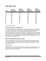
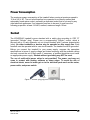
PPS Medical Series Treadmill Ergometer Owner’s Manual WOODWAY PPS Series Treadmill Ergometer In Conformity with the following standards ISO 13485:2003 FORM: PPS SERIES OWNERS MNUL REV: 02-18-2013 APPR BY: BW 1 PPS Series Includes: PPS 43” PPS 55” PPS 70” © WOODWAY USA Waukesha, WI 53186 PHONE# 262 548 6235 FAX# 262 548 6239 www.WOODWAY.com email: [email protected] European Rep: WOODWAY GmbH Steinackerstr. 20, D-79576 Weil am Rhein PHONE# +49 (0) 7621-940 999-0 FAX# +49 (0) 7621-940 999-40 www.WOODWAY.de email: [email protected] FORM: PPS SERIES OWNERS MNUL REV: 02-18-2013 APPR BY: BW 2 MY WOODWAY ________________________ (model name) ARRIVED _______________________ (date) WOODWAY SERVICE PROVIDER INFORMATION SHEET NAME OF COMPANY _________________________________________________ CONTACT PERSON _________________________________________________ ADDRESS __________________________________________________________ __________________________________________________________ PHONE NUMBER ____________________________________________________ FAX NUMBER _______________________________________________________ MAJOR CITIES AND AREAS YOUR COMPANY SERVICES ___________________ ___________________________________________________________________ ___________________________________________________________________ FORM: PPS SERIES OWNERS MNUL REV: 02-18-2013 APPR BY: BW 3 Table of Contents CHAPTER 1: GETTING STARTED ................................................................................ 6 IMPORTANT SAFETY INSTRUCTIONS ..................................................................... 7 TECHNICAL DATA .................................................................................................... 18 THINGS TO CONSIDER BEFORE STARTING EXERCISE PROGRAM ................... 19 CHAPTER 2: TREADMILL INSTALLATION ................................................................ 20 ERECTION SITE ........................................................................................................ 22 TRANSPORT/STORAGE AND DISPOSAL ............................................................... 22 POWER CONSUMPTION .......................................................................................... 23 SOCKET .................................................................................................................... 23 CHAPTER 3: TREADMILL DESCRIPTION.................................................................. 24 OPERATING THE TREADMILL ................................................................................. 31 HOW TO READ THE DATA MONITOR ..................................................................... 31 DESCRIPTION OF TREADMILL CONTROLS ........................................................... 34 SAFETY FEATURES ................................................................................................. 37 LIFTING SYSTEM (INCLINE) .................................................................................... 38 CHAPTER 4: PREVENTATIVE MAINTENANCE ......................................................... 39 CLEANING AND INSPECTION.................................................................................. 40 LUBRICATION ........................................................................................................... 41 ADJUSTMENTS AND CALIBRATION ....................................................................... 41 CHAPTER 5: REPLACING PARTS.............................................................................. 42 OUTER COVERING................................................................................................... 43 MANUAL DISPLAY .................................................................................................... 43 DRIVE MOTOR AND PULLEY ................................................................................... 43 DRIVE BELT .............................................................................................................. 44 HANDRAIL ................................................................................................................. 45 RUNNING MAT .......................................................................................................... 45 INDIVIDUAL SLATS ................................................................................................... 45 BEARING GUIDE ....................................................................................................... 46 BELT ROLLER GUIDE AND TRACK ROLLERS ....................................................... 46 FRONT AND REAR DEFLECTION ROLLERS .......................................................... 46 END SWITCHES ........................................................................................................ 47 INCLINE MOTOR ....................................................................................................... 47 CHAPTER 6: WARRANTY INFORMATION ................................................................. 48 CHAPTER 7: WRAP UP ............................................................................................... 50 TROUBLESHOOTING ............................................................................................... 51 PREVENTATIVE MAINTENANCE LOG .................................................................... 53 NUMBERS TO KNOW ............................................................................................... 54 FORM: PPS SERIES OWNERS MNUL REV: 02-18-2013 APPR BY: BW 4 WOODWAY History WOODWAY’s history began in Germany in 1974. Willi Schoenberger, a technical director in charge of planning a fitness center, noticed that the most important piece of equipment, the treadmill, did not meet the most important requirements: a mechanically sound machine that is designed to meet human needs. He envisioned a comfortable surface that did not interfere with the natural biomechanics of running or walking. Also, he wanted to design a transportation system which eliminated the friction associated with the conventional (conveyor belt) treadmills. After intensive research, and trial and error (and in cooperation with the Deutsche Sporthochschule in Koln, Germany), Willi developed and patented a very unique and revolutionary treadmill design. In 1975, WOODWAY GmbH was founded in Weil am Rhein, Germany. The name "WOODWAY" is derived from the German "Waldweg" (Wald = Wood and Weg = Way) – the feel of running on a soft pine needle covered path in the forest. In 1983, a manufacturing license was awarded to Sakai Medical, for the use of WOODWAY technology in the Japanese marketplace. In 1988, a U.S. license was granted to a small, but well-established manufacturing company in Waukesha, Wisconsin. WOODWAY USA was formed when the U.S. incarnation of the WOODWAY was developed and completed in 1990. WOODWAY USA is very proud to be the primary manufacturer of WOODWAY Treadmills worldwide, exporting treadmills each month to Germany and Japan for international distribution, in addition to serving our domestic customers and clients. Today, WOODWAY’s design and manufacturing facilities in the United States, Germany and Japan make WOODWAY the largest specialized treadmill manufacturer in the world. Constant enhancements in quality, design and function are shared and implemented by all three WOODWAY manufacturers. FORM: PPS SERIES OWNERS MNUL REV: 02-18-2013 APPR BY: BW 5 1 Chapter GETTING STARTED IMPORTANT SAFETY INSTRUCTIONS TECHNICAL DATA THINGS TO CONSIDER FORM: PPS SERIES OWNERS MNUL REV: 02-18-2013 APPR BY: BW 6 Important Safety Instructions A safety sign has been included with your treadmill. It is the responsibility of the owner to post this sign in a visible area near the machine. All WOODWAY Treadmills are built to the specifications and intended for both commercial and residential use. The main power switch is located near the location of the power cord. The switch has “I” and “O”. “I” Position: When the switch is in the “I” position the treadmill is turned on and the belt is held tight, turn the display on to operate treadmill. “O” Position: When the switch is in the “O” position the treadmill is turned off and the belt is free moving. WOODWAY Training Technique Advisory: To maximize the benefit and safety of your treadmill training WOODWAY recommends all users maintain proper running form and not shuffle their feet. When servicing any piece of fitness equipment, basic precautions must be followed. Familiarize yourself with all warnings, instructions and procedures concerning proper care and maintenance of a WOODWAY treadmill. Instructions are found in this service training manual and some also appear on labels and instructions on the treadmill itself. DANGER – To Reduce the Risk of Electrical Shock Read all instructions before using. Do not modify the plug provided with the treadmill. It is equipped with a power cord with a grounding plug. If it will not fit in the outlet, have a proper outlet installed by a qualified electrician. Never operate this appliance if it has a damaged cord or plug, if it is not working properly or if it has been damaged. Refer servicing to authorized service agent Do not use any adapters, especially ones without grounding provisions. To do so could result in electrical shock. Do not operate electrically powered treadmills in damp or wet locations. Do not operate the heart rate monitor transmitter in conjunction with an electrical heart pacemaker. The transmitter may cause electrical disturbances. FORM: PPS SERIES OWNERS MNUL REV: 02-18-2013 APPR BY: BW 7 Always unplug the treadmill immediately after using before cleaning or servicing. Do not soak the treadmill surfaces with any liquid; use a sprayer or damp cloth. Keep all electric components, such as the motor, power cord, and power switch away from water. Do not place any open liquid containers on any part of the treadmill. The use of sport bottles with closeable tops is acceptable to be used. Do not attempt to service your treadmill yourself if you feel at risk. Always keep the running surface clean. CAUTION Consult with your physician before beginning any exercise program, especially if any of the following pertain to you: history of heart disease, high blood pressure, diabetes, chronic respiratory disease, elevated cholesterol, smoke cigarettes, or experience any other chronic disease or physical impairments. Pregnant women should consult their physician before beginning an exercise program. If you experience dizziness, chest pains, nausea or any other abnormal symptoms while utilizing the treadmill, stop immediately. Consult a physician before continuing. A qualified mechanic should perform service or repair work. It is preferable that mechanics have successfully completed our factory-authorized service school or equivalent. Fuses may only be replaced by fuses of the same time and rated output to provide permanent protection from fire. WARNING – To reduce the risk of injury to you and to others: Set up and operate treadmills on a solid, level surface. Use this appliance only for its intended purpose as described in the manual. Do not use attachments not specified by the manufacturer The treadmill should never be left unattended when plugged in. Unplug from outlet when not in use and before putting on or taking off parts. FORM: PPS SERIES OWNERS MNUL REV: 02-18-2013 APPR BY: BW 8 Do not operate outdoors. To disconnect turn all controls to off position then remove plug from outlet. Connect this treadmill to a properly grounded outlet only. See Grounding instructions. Keep all loose clothing and towels away from the treadmill running surface. It is also important that shoe laces do not extend past the bottom of the sole of the shoe. Keep the area behind the treadmill clear and at least 2 METERS / 6.6 FEET from walls or furniture. Keep hands away from all moving parts. Never leave children unsupervised around a treadmill. Inspect the treadmill for worn or loose components prior to use. Tighten/replace any worn or loose components prior to use. Read, understand and test the emergency stop procedures. ALWAYS USE THE EMERGENCY SAFETY LANYARD SUPPLIED WITH THE TREADMILL! It can be clipped to an article of clothing while exercising. This is for your safety in case an emergency arises. WOODWAY treadmills are built to handle runners weighing up to 800 pounds at speeds between 0-4 MPH and 400 pounds at speeds up to 15 MPH. A treadmill running belt might not stop immediately if any object becomes caught in the belt or rollers. Care should be taken when mounting and dismounting the treadmill. Never mount or dismount the treadmill while the running belt is moving. Use the handlebar or handrails whenever practical. Wear proper athletic shoes, such as those with rubber or high-traction soles. Do not use shoes with heels or leather soles. Make sure no stones are embedded in the soles. Allow several minutes to bring your heart rate into the training zone shown elsewhere in this manual. Walk slowly after your workout to allow your body time to cool down and your pulse rate to decrease. The safety and integrity designed into the machine can only be maintained when the treadmill is regularly examined for damage and repaired. It is the sole responsibility FORM: PPS SERIES OWNERS MNUL REV: 02-18-2013 APPR BY: BW 9 of the user/owner or facility operator to ensure that regular maintenance is performed. Worn or damaged components should be replaced immediately or the treadmill removed from service until the repair is made. Only manufacturer supplied or approved components should be used to maintain and repair the treadmill. Don’t mount the treadmill during the initialization process (i.e. the display not fully initialized) Handicapped persons (fragile, mentally handicapped, etc.) should never mount the treadmill without the help of the therapist For handicapped persons (fragile, mentally handicapped, etc.) the therapist must balance between the risks and benefits of the use of the treadmill The following points must always be observed to protect from burns, electric shocks and injuries: 1. Never leave the treadmill connected and running without supervision. Before leaving the machine, stop it and disconnect it from the mains. To do so, switch all control elements to STOP or OFF and then pull the plug out of the socket. This procedure is always necessary when the treadmill is at a standstill and before dismantling any parts. 2. The treadmill must be continuously monitored when used in the vicinity of children or physically and mentally disabled persons. 3. The treadmill may only be used for the purposes described in this manual. 4. Never operate a treadmill with defective plug or cable or a running mat which is damaged or not functioning correctly. 5. The cable should not come in contact with heating surfaces or sharp edges. 6. No objects of any kind may fall through the openings or onto moving machine components. Also keep hands, hair, loose clothing, towels etc. away from the moving treadmill. 7. Only qualified maintenance staff can carry out electrical and mechanical repair work. Please contact your dealer, the Service Center, or the WOODWAY factory directly. Only original spares may be used. 8. The treadmill must be connected to a correctly earthed socket. Please consult the section on earthing the system. FORM: PPS SERIES OWNERS MNUL REV: 02-18-2013 APPR BY: BW 10 Earthing the system The treadmill must be correctly earthed. In the event of a malfunction or failure of components, the earthing device provides the route of least resistance for the electric current, thus reducing the risk of electric shocks. The unit is equipped with a mains cable with earthed plug. The plug must be connected to a suitable, correctly fitted and earthed mains socket. DANGER: The plug supplied with the treadmill should not be manipulated in any way. If necessary, a suitable mains socket must be fitted by a qualified electrician. Adapters may not be used because of the risk of electric shocks. **Save these instructions FORM: PPS SERIES OWNERS MNUL REV: 02-18-2013 APPR BY: BW 11 Instructions de sécurité importantes Un signe de la sécurité ont été inclus avec votre tapis de course. C'est la responsabilité du propriétaire pour envoyer ce signe dans un endroit visible près de la machine. Tous les tapis de course Woodway sont construits conformément aux spécifications et destinés tant à usage commercial et résidentiel. L'interrupteur d'alimentation principal est situé à proximité de l'emplacement du cordon d'alimentation. Le commutateur a "I" et "O". Position "I": Lorsque l'interrupteur est en position "I" du tapis roulant est allumé et que la ceinture est maintenue solidement, tourner l'écran pour fonctionner sur tapis roulant. Position "O": Lorsque l'interrupteur est en position "O" du tapis roulant est désactivé et que la ceinture est libre de se déplacer. Woodway formation technique consultatif: Pour maximiser les avantages et la sécurité de votre entraînement sur tapis roulant Woodway recommande à tous les utilisateurs à maintenir bonne et due forme en cours d'exécution et non shuffle leurs pieds. Lors de l'entretien toute pièce d'équipement de conditionnement physique, les précautions de base doivent être suivies. Familiarisez-vous avec tous les avertissements, instructions et procédures concernant les soins et l'entretien d'un tapis roulant Woodway. Les instructions se trouvent dans cette formation, manuel de service et certains apparaissent aussi sur des étiquettes et des instructions sur le même tapis roulant. FORM: PPS SERIES OWNERS MNUL REV: 02-18-2013 APPR BY: BW 12 DANGER - Pour réduire le risque de choc électrique • Lisez toutes les instructions avant d'utiliser. • Ne pas modifier la fiche fournie avec le tapis roulant. Il est équipé d'un cordon d'alimentation avec une fiche de terre. Si elle ne tient pas dans la prise, faites installer une prise adéquate par un électricien qualifié. • Ne jamais faire fonctionner cet appareil si l'on dispose d'un câble ou une prise endommagée, si elle ne fonctionne pas correctement ou s'il a été endommagé. Reportez-vous au service de l'agent de service autorisé • Ne pas utiliser toutes les cartes, surtout celles sans terre dispositions. Pour cela pourrait provoquer un choc électrique. • Ne pas faire fonctionner les tapis roulants électriques dans des endroits humides ou mouillés. • Ne pas faire fonctionner l'émetteur moniteur de fréquence cardiaque en conjonction avec un stimulateur cardiaque électrique. L'émetteur mai causer des perturbations électriques. • Débranchez toujours le tapis de course juste après avoir utilisé avant le nettoyage ou l'entretien. • Ne pas tremper le tapis roulant de surfaces avec un liquide, l'utilisation d'un pulvérisateur ou un chiffon humide. Conservez tous les composants électriques, tels que le moteur, cordon d'alimentation, et l'interrupteur éloigné de l'eau. • Ne placez pas de récipients ouverts liquide sur n'importe quelle partie du tapis roulant. L'utilisation de bouteilles de sport avec des sommets closeable est acceptable pour être utilisé. • N'essayez pas de réparer vous-même votre tapis de course si vous vous sentez en danger. • Toujours maintenir la surface de roulement propre. FORM: PPS SERIES OWNERS MNUL REV: 02-18-2013 APPR BY: BW 13 ATTENTION • Consultez votre médecin avant de commencer tout programme d'exercice, surtout si l'un des suivants se rapportent à vous: des antécédents de maladie cardiaque, d'hypertension artérielle, le diabète, les maladies respiratoires chroniques, le taux de cholestérol élevé, fument des cigarettes, ou une expérience toute autre maladie chronique ou physique déficiences. • Les femmes enceintes devraient consulter leur médecin avant de commencer un programme d'exercice. • Si vous éprouvez des vertiges, douleurs thoraciques, des nausées ou tout autre symptôme anormal, tout en utilisant le tapis roulant, arrêtez immédiatement. Consultez un médecin avant de poursuivre. • Un mécanicien qualifié doit effectuer un service ou une réparation. Il est préférable que les mécaniciens ont complété avec succès notre usine, l'école de service autorisé ou l'équivalent. • Les fusibles ne peuvent être remplacés par des fusibles de la même époque avec une sortie pour fournir une protection permanente contre les incendies. AVERTISSEMENT - Pour réduire le risque de blessures à vous et à d'autres: • Mettre en place et exploiter des tapis roulants sur une surface solide et de niveau. • Utiliser cet appareil que pour son objectif tel que décrit dans le manuel. N'utilisez pas d'accessoires non spécifiés par le fabricant • Le tapis de course ne doit jamais être laissé sans surveillance lorsqu'il est branché po Débranchez l'appareil lorsqu'il n'est pas utilisé et avant de mettre ou de retirer des pièces. • Ne pas faire fonctionner à l'extérieur. • Pour débrancher son tour tous les contrôles sur la position OFF puis retirez la prise de la prise. • Relier cette tapis roulant à une prise correctement mise à la terre seulement. FORM: PPS SERIES OWNERS MNUL REV: 02-18-2013 APPR BY: BW 14 Voir les instructions Grounding. • Gardez les vêtements amples et des serviettes loin de la course sur tapis roulant de surface. Il est également important que les lacets de souliers ne s'étendent pas au-delà du fond de la semelle de la chaussure. • Garder la zone située derrière le tapis roulant claire et pieds au moins quatre de murs ou les meubles. • Gardez les mains loin de toutes les pièces mobiles. • Ne laissez jamais d'enfant sans surveillance autour d'un tapis roulant. • Inspecter le tapis roulant pour les composants usés ou en vrac avant de les utiliser. Serrez / remplacer les éléments usés ou en vrac avant de les utiliser. • Lire, comprendre et tester les procédures d'arrêt d'urgence. • TOUJOURS UTILISER LE CORDON DE SECURITE EN CAS D'URGENCE FOURNIE AVEC LE TAPIS DE COURSE! Il peut être fixé à un vêtement pendant l'exercice. Ceci est pour votre sécurité en cas d'urgence. • Tapis de course Woodway sont construites pour gérer les coureurs pesant jusqu'à 800 livres à des vitesses comprises entre 0-4 km / h et 400 livres à une vitesse allant jusqu'à 15 mph. Un tapis roulant courroie peut pas s'arrêter immédiatement si un objet est pris dans la ceinture ou de rouleaux. • Des précautions doivent être prises lors du montage et le démontage du tapis roulant. Ne jamais monter ou démonter le tapis roulant alors que la courroie est en mouvement. Utilisez le guidon ou les mains courantes autant que possible. • Portez des chaussures de sport, tels que ceux de caoutchouc ou de semelles de traction élevé. N'utilisez pas de chaussures à talons ou les semelles de cuir. Assurez-vous qu'aucun des pierres sont ancrés dans la plante des pieds. • Autoriser plusieurs minutes pour apporter votre rythme cardiaque dans la zone d'entraînement figurent ailleurs dans ce manuel. Marchez lentement après l'entraînement pour permettre à votre corps le temps de se refroidir et votre pouls à diminuer. • La sécurité et l'intégrité conçus dans la machine ne peut être maintenue lorsque FORM: PPS SERIES OWNERS MNUL REV: 02-18-2013 APPR BY: BW 15 le tapis roulant est régulièrement examiné et réparé. Il s'agit de la seule responsabilité de l'utilisateur / le propriétaire ou l'exploitant de l'installation pour s'assurer que l'entretien régulier est effectué. Les éléments usés ou endommagés doivent être remplacés immédiatement ou le tapis roulant retiré du service jusqu'à ce que la réparation est effectuée. Seul fabricant de composants fournis ou approuvés devraient être utilisées pour entretenir et réparer le tapis roulant. • Ne montez pas le tapis roulant pendant le processus d'initialisation (c'est à direl'affichage n'est pas complètement initialisé) • Les personnes handicapées (fragiles, handicapés mentaux, etc) ne doivent jamais monter le tapis roulant sans l'aide du thérapeute • Pour les personnes handicapées (fragiles, handicapés mentaux, etc), le thérapeute doit établir un équilibre entre les risques et les avantages de l'utilisation du tapis roulant Les points suivants doivent toujours être respectées afin de protéger des brûlures, des chocs électriques et les blessures: 1. Ne laissez jamais le tapis roulant connectés et le fonctionnement sans surveillance. Avant de quitter la machine, l'arrêter et le débrancher du réseau électrique. Pour ce faire, passer tous les éléments de contrôle pour arrêter ou OFF, puis retirez la fiche de la prise. Cette procédure est toujours nécessaire quand le tapis roulant est à l'arrêt et avant de démonter toutes les pièces. 2. Le tapis de course doit être surveillé continuellement, lorsqu'ils sont utilisés à proximité des enfants ou des handicapés physiques et mentaux des personnes. 3. Le tapis de course ne peuvent être utilisées aux fins décrites dans ce manuel. 4. Ne jamais utiliser un tapis roulant avec prise défectueuse ou un câble ou un tapis de marche qui est endommagé ou ne fonctionne pas correctement. 5. Le câble ne doit pas entrer en contact avec des surfaces de chauffage ou de bords tranchants. 6. Pas d'objets de toute nature peuvent tomber à travers les ouvertures ou sur des composants mobiles de la machine. Aussi gardez vos mains, cheveux, vêtements, serviettes, etc loin de le tapis roulant en mouvement. 7. Seul le personnel d'entretien qualifié peut effectuer des réparations électriques et mécaniques. S'il vous plaît contactez votre revendeur, le centre de service, ou à l'usine Woodway directement. Seuls les pièces de rechange d'origine peuvent être utilisés. 8. Le tapis de course doit être raccordé à une prise correctement mise à la terre. S'il vous plaît consulter la section sur le système de mise à la terre. Mise à la terre du système FORM: PPS SERIES OWNERS MNUL REV: 02-18-2013 APPR BY: BW 16 Le tapis de course doit être correctement mis à la terre. En cas de dysfonctionnement ou de défaillance des composants, le dispositif de mise à la terre fournit l'itinéraire le moins de résistance au courant électrique, réduisant ainsi le risque de chocs électriques. L'unité est équipée d'un câble d'alimentation avec prise de terre. La fiche doit être connectée à un convenable, prise de courant correctement mis en place et mise à la terre. DANGER: La fiche fournie avec le tapis roulant ne doit pas être manipulé d'aucune façon. Si nécessaire, une prise de courant appropriée doit être installé par un électricien qualifié. Adaptateurs ne peut être utilisée en raison du risque de chocs électriques. ** Conservez ces instructions FORM: PPS SERIES OWNERS MNUL REV: 02-18-2013 APPR BY: BW 17 Technical Data Mechanical Data Overall dimensions: Weight: Stand: Maximum load-bearing capacity: Speed range: Incline range: Running mat acceleration: 6 ft. (L) x 2.85 ft. (W) x 4 ft. (H) Approx. 485 lbs four (4) rubber feet 400 lbs running, 800 lbs walking 0 to 12.5 mph 0 to 25% with data-monitor fully adjustable up to max. speed Electrical Data Mains connection: Motor: Drive: Resolution: Lifting motor: Mains cable: Main fuse: Fuse for lifting drive: 230 V AC 16 A, 50/60 Hz DC with tachometer 1 kW threaded rod and pinion 0.1 % DC motor 150 W 2.5 m, 2 pole CEE 7/7 (earthed safety plug) 10 A slow-acting fuses, 0.5 x 2 cm (in control) 5 A slow-acting fuses, 0.5 x 2 cm (in control) Treadmill Data General: Running mat type Hardness of mat: Mat surface: Color: Support system: Lateral play: FORM: PPS SERIES OWNERS MNUL REV: 02-18-2013 APPR BY: BW 60 slats, width 43 cm, replaceable rubber on aluminum support approx. 40 Shore D 156 cm x 43 cm Grey 106 ball bearings with 12 V-belt guides +/- 2 mm 18 Things to Consider Before Starting Exercise Program CONSULT A PROFESSIONAL FITNESS TRAINER It is advisable for all exercise beginners to consult a professional fitness instructor or personal trainer to develop an overall fitness evaluation/wellness program before starting an exercise routine. CONSULT A PHYSICIAN If you are over 40, have a history of heart disease, are overweight, or have not been involved in any kind of exercise program for several years, it is recommended that you see your physician as a precaution before engaging in a vigorous exercise program. UNDERSTAND THE IMPORTANCE OF WARMING UP AND COOLING DOWN It is important to warm up and cool down prior to and at the end of each work out, respectively. Always try to incorporate a series of basic leg stretches before and after each workout. Stretching provides the necessary flexibility to prevent sore muscles and injury during daily activities. LEARN HOW TO TAKE YOUR PULSE PROPERLY To select the Fitness Level that is most suitable to exercise, it is important to correctly determine your heart rate or pulse. To do this, it is recommended that you use a good quality heart rate monitor. If you do not have a heart rate monitor, you can find your pulse by placing your fingers on the underside of your wrist or either side of your throat. While looking at the second hand on your watch, count how many heartbeats you feel within fifteen (15) seconds. Multiply this number by four to get your Beats Per Minute (BPM). Your heart rate will be needed when you take the Self-Fitness Test. KNOW YOUR MAXIMUM HEART RATE To determine your maximum heart rate, subtract your age from 220 (general formula). The difference is the approximation of your maximum heart rate, as used by the American Heart Association and The American College of Sports Medicine. The only way to determine your true maximum heart rate is to have a stress test administered by your physician. The American Heart Association recommends that you have a stress test done if you have any history of heart disease or if you are over the age of 40 and beginning an exercise program. During exercise, it is recommended that you not exceed 85% of your maximum heart rate. Our programs are designed to keep your heart rate within your Target Zone. Your Target Zone is an area between 60 and 75% of your maximum heart rate. Should you find your heart rate above the 75% level, you have probably selected a Fitness Level that is too high in that particular Fitness Program. You should either drop to a lower intensity level in the same Fitness Program, or use a less stressful Fitness Program. FORM: PPS SERIES OWNERS MNUL REV: 02-18-2013 APPR BY: BW 19 Heart Rate Chart AGE MAXIMUM HEARTRATE 60% OF MAXIMUM HEART RATE 20 25 30 35 40 45 50 55 60 65 70 75 200 BPM* 195 190 185 180 175 170 165 160 155 150 145 120 BPM 120 110 110 100 100 100 90 90 90 90 80 75% OF MAXIMUM HEART RATE 85% OF MAXIMUM HEART RATE 150 BPM 150 140 130 130 130 120 120 120 110 110 100 170 BPM 160 160 150 150 140 140 130 130 130 120 120 * BPM = Beats Per Minute HOW OFTEN SHOULD YOU EXERCISE? The biggest mistake made by people when starting an exercise program is that they try to do too much too fast. Give yourself time to get into shape. Becoming reconditioned also takes time. Either way, it will not happen overnight. Remember: the key is consistency and duration of exercise, not intensity. Fitness experts recommend that you start by exercising three to four days a week within your target heart rate for at least 20 minutes per session. Your ultimate goal should be to get yourself gradually to a level of fitness where you can comfortably keep your heart rate in the Target Zone for 50 to 60 minutes four to five times a week. WEAR PROPER WALKING/JOGGING SHOES To help avoid getting sore feet and muscles, it is suggested that you invest in a good pair of walking/jogging shoes. It is important to purchase a comfortable pair of shoes with good heel and arch support. Also, remember to regularly replace old or worn out shoes with new shoes. STAY ACTIVE Between workouts it is suggested that you simply stay active, eat well-balanced meals, and drink plenty of water. The combination of these activities should enhance your chances for a future of good health. FORM: PPS SERIES OWNERS MNUL REV: 02-18-2013 APPR BY: BW 20 2 Chapter TREADMILL INSTALLATION ERECTION SITE TRANSPORT/STORAGE AND DISPOSAL POWER CONSUMPTION SOCKET FORM: PPS SERIES OWNERS MNUL REV: 02-18-2013 APPR BY: BW 21 Erection Site In most cases, your WOODWAY treadmill will be delivered completely assembled. Check immediately upon delivery for any signs of transport damage. Please report all damage immediately to the transport company and to the factory. The treadmill must be installed on a flat, sufficiently firm floor surface. When installed on higher stories, ensure that the system is positioned as far as possible in the corner of the rooms to ensure sufficient stability even when running at higher speeds. The erection site must be as flat as possible to ensure minimum deflection of the frame. The treadmill may not be erected directly on carpet with relatively long pile because of the moving parts on the underside of the treadmill. If necessary, a suitable mat should be placed under the treadmill. This prevents carpet from being caught up in the treadmill, and also reduces wear on the carpet surface. Transport/Storage and Disposal DELIVERY: The treadmill is heavy and can cause injury if lifted incorrectly. Always use the supplied carrier poles if the treadmill is to be moved. Never use the covers to lift or pull the treadmill. If a flat trolley is available, slide the trolley under the treadmill and then move the treadmill to its new position. If the treadmill has to be dismantled, the covers and railings can be taken down for easier transport. Do only store in closed or roofed over rooms. DISPOSAL: Note: The disposal has to be proceeded according to the national regulations each. Refer to appropriate disposal enterprises. The treadmill packing is to be supplied to recycling services. The metallic parts of the treadmill are to be supplied to disposal of old-metal. Plastic parts are to be supplied to recycling services. Electric components and circuit boards are to be disposed as electronic scrap. Rubber parts are to be disposed as special refuse. FORM: PPS SERIES OWNERS MNUL REV: 02-18-2013 APPR BY: BW 22 Power Consumption The maximum power consumption of the treadmill when running at maximum speed is 10 A at 240 V AC. The unit must therefore be connected to a correctly earthed and adequately fused mains socket, preferably a dedicated socket that is not used by any other electrical appliances. If an extension lead has to be used, it must have the following properties: at least 14 AWG, earthed, maximum length 10 feet. Socket The WOODWAY treadmill comes standard with a safety plug according to CEE 7/7 (grounded “Schuko" plug). Please use a corresponding “Schuko” socket, which is secured with a 16 amp automatic cut-out (circuit breaker) with C-release characteristic (slow). No other treadmills or devices may be operated on this supply line. Each treadmill must be operated with its own circuit breaker. The treadmill must be grounded. Before you connect the treadmill to your power supply, compare the nameplate specifications in terms of supply voltage and mains frequency with the available values and only connect the unit if they match. If necessary, a qualified electrician must install an appropriate power supply. Sockets without grounding may NOT be used. The use of multi-outlet power strips is not permitted! The power cord may not come in contact with heating surfaces or sharp edges. To avoid the risk of electrical shock, never let water get on to the electrical parts such as the motor, power cable, and power switch. Figure 1: “Schuko" plug (left) and “Schuko" socket (right) FORM: PPS SERIES OWNERS MNUL REV: 02-18-2013 APPR BY: BW 23 3 Chapter TREADMILL DESCRIPTION PPS SERIES DETAILS TREADMILL COMPONENTS OPERATING THE TREADMILL DATA MONITOR DESCRIPTION OF CONTROLS SAFETY FEATURES LIFTING SYSTEM (INCLINE) FORM: PPS SERIES OWNERS MNUL REV: 02-18-2013 APPR BY: BW 24 PPS Series Details PPS Med Line General Description Model Slat Running Surface Area 60 slats with 35-40 shore hardness LxW Overall Dimensions LxWxH Speed, infinitely variable Inclination, infinitely variable Total Weight Maximum Loading FORM: PPS SERIES OWNERS MNUL REV: 02-18-2013 APPR BY: BW PPS 43 17” x 68” 173 x 43 cm PPS 55 22” x 68” 173 x 55 cm PPS 70 27” x 68” 173 x 70 cm 72” x 34” x 52” 183 x 86 x 132 cm 0-12.5 mph 0-18 km/h 0-25% 460 lb 209 kg 800 lb 363 kg 72” x 38” x 52” 183 x 97 x 132 cm 0-12.5 mph 0-20 km/h 0-25% 490 lb 222 kg 800 lb 363 kg 72” x 47” x 52” 183 x 119 x 132 cm 0-12.5 mph 0-20 km/h 0-25% 520 lb 235k 800 lb 363 kg 25 PPS Med 43 PPS Med 55 PPS Med 70 FORM: PPS SERIES OWNERS MNUL REV: 02-18-2013 APPR BY: BW 26 PPS Bari-Mill General Description Model Slat Running Surface Area 60 slats with 35-40 shore hardness LxW Overall Dimensions LxWxH Speed, infinitely variable Inclination, infinitely variable Total Weight Maximum Loading FORM: PPS SERIES OWNERS MNUL REV: 02-18-2013 APPR BY: BW PPS Bari-mill 43 17” x 68” 173 x 43 cm PPS Bari-mill 55 22” x 68” 173 x 55 cm PPS Bari-Mill 70 27” x 68” 173 x 70 cm 72” x 34” x 52” 183 x 86 x 132 cm 12.5 mph 0-18 km/h 0-25% 480 lb 218 kg 800 lb 363 kg 72” x 38” x 52” 183 x 97 x 132 cm 0-12.5 mph 0-20 km/h 0-25% 510 lb 231 kg 800 lb 363 kg 72” x 47” x 52” 183 x 119 x 132 cm 0-12.5 mph 0-20 km/h 0-25% 540 lb 245 kg 800 lb 363 kg 27 PPS Bari-Mill 43 PPS Bari-Mill 55 PPS Bari-Mill 70 FORM: PPS SERIES OWNERS MNUL REV: 02-18-2013 APPR BY: BW 28 Product Labels ELECTRICAL EQUIPMENT CLASS I TYPE B ENCLOSURE: IP2X NOTE-GROUNDING RELIABILITY CAN ONLY BE ACHIEVED WHEN THIS EQUIPMENT IS CONNECTED TO AN EARTH-GROUNDED RECEPTACLE MARKED "HOSPITAL GRADE" Warning: Disconnect from supply circuit before opening. Attention: Débrancher circuit avant l'ouverture. FORM: PPS SERIES OWNERS MNUL REV: 02-18-2013 APPR BY: BW 29 Treadmill Components Running Mat: The patented running mat consists of 60 individual slats fitted on a set of continuous toothed belts. The toothed belts engage in the front crown wheel and this in turn engages in the drive motor. This makes it completely impossible for the treadmill to slip. The individual slats consist of two materials: a rubber surface, and an aluminum Tsection. This combination of approximately 1.2 cm rubber on aluminum T-sections makes it "the softest treadmill in the world". The rubber surface is resilient and considerably reduces vibrations. This, in turn, effectively reduces and delays the occurrence of pain in the legs which frequently accompany long-term running. The positive belt structure eliminates friction and warmth, thus increasing the service life of the treadmill surface. Transport System: The transport system consists of two support rails: a steel wire reinforced continuous belt, and 17.8 cm O. The support rails with 112 ball bearings support the running mat and make an essential contribution to reducing wear and friction. The two lateral continuous belts have several key functions: they hold the slats together, transfer output to and from the motor to the runner, and reduce the mat from slipping out to the left or right. The two support rails consist of three main components: the support rail, individual ball bearings and mounted roller guides. The smooth area of the lateral belts runs over the ball bearings and roller guides. The support rails accommodate all ball bearings and roller guides and distribute local load evenly across the whole running mat. The ten roller guides support the running mat and prevent it from slipping out to the left or right. The 56 individual bearings on each side also make an important contribution to even distribution of load across the whole running mat. The deflection rollers transfer the load to and from the motor and prevent the mat from slipping through. The front deflection roller is equipped with an additional crown gear used by the motor. All deflection rollers are equipped with heavy-duty bearings which also reduce friction. This unique transport system thus provides extremely low friction and can even be used without external drive, simply by pushing the treadmill to get it started. FORM: PPS SERIES OWNERS MNUL REV: 02-18-2013 APPR BY: BW 30 Operating the Treadmill Before switching the treadmill on, the person operating the machine must check that the emergency solenoid is correctly position. Otherwise the display will not light up. Then press the ON key. The display now lights up. To adjust speed or incline, the person operating the machine presses the corresponding buttons and checks the displays. The time and distance can be reset to zero by pressing the RESET button. The person operating the machine can select between various display modes by pressing the MPH / m/s / km/h button. This does not influence the TIME display. How to Read the Data Monitor Introduction: The data monitor described here indicates the current parameters of the treadmill. The device has 4 multi-digit displays to indicate the current exercise parameters, as well as several LEDs to indicate the control mode. The data monitor displays the following values: Speed of the treadmill in meters per second or kilometers per hour. Adjusted incline of the treadmill in percent. The distance run in meters since the belt was last started. The energy burnt in calories. The exercising time. The current pulse rate (if the treadmill is fitted with a pulse receiver). The control mode of the treadmill (remote control/manual operation/stop mode) The LEDs to the right of the displays indicate the unit of the displayed value, or to distinguish between various parameters presented on the same display. The data monitor is only a display unit with limited facilities to control the treadmill. FORM: PPS SERIES OWNERS MNUL REV: 02-18-2013 APPR BY: BW 31 Speed Display: The top three-digit display indicates the current speed of the treadmill. The displayed speed in miles per hour is set with a key to the right of the display. The two LEDs between the display and key indicate which of the two units is currently activated. The sign in front of the displayed value can be used to indicate a backward running belt in the event that the treadmill offers such a facility. Distance and Burnt Calories Display: The display alternates in 10-second cycles between the distance in miles since the treadmill was last switched on, and the calories burnt by the runner. The upper LED is assigned to the distance value, the lower one to the calories burnt. The values for distance and calories are retained after the treadmill is stopped. They are deleted following renewed start of the treadmill via the hand-rail keypad or the remote control. Exercise Time Display: The exercise duration is reset to zero each time the treadmill is restarted. The display includes minutes and seconds that have elapsed since the treadmill was started. The two values are separated by two dots which flash to indicate seconds. The display changes over to hours and minutes when the training duration exceeds one hour. The top LED is then turned off and the bottom starts to flash in its place to indicate the new status. Incline and Pulse Rate Display: These two values are also indicated by the same display. The incline, just as the speed value, is preceded by a sign. However, a negative sign can only be indicated if the treadmill features such a facility. The incline direction can only be changed via PC with a remote control or with the hand-rail keypad. After a change of incline, the new value is indicated for 5 seconds on the display. The upper of the two LEDs alongside the display is active for this purpose. The current pulse rate of the runner is displayed after this 5-second period if the incline remains unchanged; this status is indicated by the bottom LED. Unless incline is being changed, the display will only return to the incline value when the radio link to the pulse sensor on the body of the runner is interrupted. The monitor will display the incline value if the treadmill does not feature a pulse sensor. FORM: PPS SERIES OWNERS MNUL REV: 02-18-2013 APPR BY: BW 32 Treadmill Control Mode Display: The control mode is displayed by five LEDs on the right-hand side of the monitor. The significance of the LEDs (from top to bottom) is as follows: Manual control via the hand-rail keypad is active. The treadmill is in stop mode (it is only possible to change the running direction and start the running or pulse programs via a PC in this mode). Remote control (running/pulse program) started from a PC or other accessory unit. Change of running direction is possible. Backward running direction is active (the belt runs backwards when it is started with the plus key on the hand-rail; a negative speed is displayed. Control Unit of the Data Monitor: The data monitor features three keys and one EMERGENCY STOP switch. As previously described, the first key changes the unit of speed. The second key (underneath) changes the running direction of the belt. The treadmill will only react to the depression of this key if the LED indicates that the changeover facility is active (fourth mode display LED from the top). A change of running direction is indicated by the running direction LED (fifth from the top). The button underneath these two keys stops the treadmill during an exercise session. The speed is slowly reduced until the belt comes to stop. The incline adjusted before the key was actuated is retained. Once the belt has stopped the treadmill is changed over to stop mode (indicated by the second mode LED from the top). The red emergency stop button at the bottom right-hand side of the data monitor bypasses the electronic control and instantly stops the treadmill in an emergency. WARNING: Instant stop is with a jerk, as opposed to a slowed down stop. AVERTISSEMENT: arrêt instantané est d'un coup, par opposition à un arrêt de ralenti. Note: After an emergency stop the treadmill must be switched on again for a renewed start. FORM: PPS SERIES OWNERS MNUL REV: 02-18-2013 APPR BY: BW 33 Description of Treadmill Controls Overview and Basic Functions: The WOODWAY treadmill control is equipped with various elements which adjust the speed and incline systems, allowing for complex control sequences and carrying out of safety and monitoring functions together with pulse measurement. The hardware consists of a micro-controller system based on the SAB80C537 with peripheral switching to the motor control and sensory components and to the control interfaces. The following control units can be connected as options for parallel operation: Function buttons (FASTER / SLOWER / UP / DOWN / STOP / FAST STOP) LED display for speed / incline / time / distance / pulse (in preparation) WUS (LCD touch display with menu guide and access to complex functions) Chip card connection component in WUS PC / ECG equipment or similar via serial interface (implementing various protocols) The control assumes the following basic functions: Measurement and control of speed and incline Measurement of time, distance, and pulse Interpretation of control activities with safety priority control Time control for running programs Interactive pulse control Entry and monitoring of parameters for limit and operating values Operating hours counter for switch-on and running time, total distance, incline mode Monitoring and safety functions Treadmill Control: Once the system has been switched on, the control is in the initial status. It can be switched to four different control modes: Manual mode / WOODWAY standard protocol External protocol (e.g. ECG appliance) Program control Pulse control (interactive) Each of these control modes has a STOP and a RUN status. Transition between the control modes can be triggered by RS232 commands or from the railing panel. The WOODWAY standard protocol allows for "remote controlled" manual mode, for direct specification of speed and incline and for a query to see all measured values and some parameters (see command list). Access to the more FORM: PPS SERIES OWNERS MNUL REV: 02-18-2013 APPR BY: BW 34 complex control procedures of the program and pulse control or to the internal treadmill parameters is not possible. Only the initial status, the STOP hand mode and the RUN hand mode are of interest and will be described briefly below. In the initial status, speed and incline are both zero; the current time and distance are retained. These are set to 0 when re-starting. It is possible to return to the initial status with the WOODWAY standard protocol from all RUN modes by entering the command "treadmill STOP" and then repeating the command again once the treadmill has stopped (corresponding STOP status, current speed = 0). (Transition from current STOP status to initial status). The status STOP manual mode can only be reached from the RUN mode by pressing the STOP button or by the RS232 command "STOP treadmill" (interruption). No speed setting commands are accepted in the STOP mode. The current incline, time and distance remain. Re-start is only possible once the treadmill has come to a standstill by pressing the "+" button or entering the RS232 command "release treadmill" and then entering a speed value. In the STOP modes, the STOP button can be pressed or RS232 command "STOP treadmill" entered to return to the initial status. Enter the command "release treadmill" from the initial status or STOP manual mode to reach the RUN manual mode. This is the prerequisite for accepting speed setting commands. The treadmill knows four different possibilities for changing the speed, with separate allocated acceleration rates: "+" / "-" button (physical buttons or RS232 command "Set buttons!") Speed setting command (RS 232 command "set speed!") Normal stop (STOP button or RS232 command "STOP treadmill") Fast stop (only possible by pressing FAST STOP BUTTON), with maximum acceleration The maximum, button and RS232 acceleration can be queried in the WOODWAY standard protocol and the RS232 acceleration set here. On the railing panel, the pressed "+" button (status) has the same effect as the command "release treadmill", and the front flank of the "STOP" button has the same effect as the command "STOP treadmill", each with the corresponding changes in status. The same effect is achieved when the buttons are allocated RS232 commands. There is generally no difference between physical and software button control. The TIME-OUT mode can be activated to monitor correct RS232 communication. This is useful when on-going cyclic data exchange takes place. This mode offers additional safety should the PC program fail or if the treadmill extension lead should be disconnected. If a correct, complete telegram is not received within a set time, the speed set value is set to 0 and the treadmill is stopped (effect as the STOP button). The TIME-OUT time can be changed via RS232 between 0.1 ... 9.9 seconds. A value of 0 deactivates the control function. In the WOODWAY standard protocol, the function is FORM: PPS SERIES OWNERS MNUL REV: 02-18-2013 APPR BY: BW 35 initially inactive. It can be activated at any time via RS232 by entering a time > 0, and deactivated again by setting the time to 0. It is always possible to query the current measured values for speed, incline, time, distance and pulse, regardless of the current control status. The set commands are only accepted when these are permitted in the current control mode. The only setting command of the WOODWAY standard protocol which is also valid in the program control status, external control status and pulse control status is the command "STOP treadmill". RS232 - Interface with WOODWAY Standard Set of Commands: The control only needs the lines TxD and RxD. The RS232 control lines are bridged in such a way that there should not be any problems in communicating with a PC running under DOS or WINDOWS. Galvanic separation rules out the risk of any interference in the PC from the treadmill. A crossed zero modem cable is required as used to connect two PCs with normal standard pin configuration. The interface is configured to the following parameters: 9600 Bd / 8 Bit / no parity / 1 Stopbit On the software side, the interface is provided with a buffer of 256 bytes for both transmitting and receiving. Transmission and reception take place interrupt- controlled. A command is not interpreted until it is fully present in the buffer. The interpretation proceeds with full control of the command format. Only correct commands are executed. The interface responds to faults with 0Dh (multiple responses if necessary). The interface is not blocked by incorrect commands, and the beginning of the next correct command is also recognized. A valid command refreshes the TIME-OUT if this mode is activated. Excessive values for individual parameters are reduced to the maximum tolerable levels without producing fault messages. The buffer configuration means that several commands can be transmitted to the interface in direct succession. They can be executed in sequence at the maximum possible speed (normal interpretation times are in the ms range). However, the PC programmer is responsible for preventing overflow of the transmission or reception buffer. This is vital to ensure that no overflows occur during successive transmission of several commands which do not wait for a response (add the telegram lengths of command and response, the total must always be less than 256). FORM: PPS SERIES OWNERS MNUL REV: 02-18-2013 APPR BY: BW 36 Safety Features CAUTION: USE EMERGENCY STOP SWITCH IMMEDIATELY IF PROBLEM ARISES. ATTENTION: en cas d'urgence STOP immédiatement la commande si problème se pose. Magnetic Emergency Stop Switch (Lanyard System): The magnetic emergency stop switch consists of a contact-free switch (break contact) which is mounted on the WUS/data monitor or on the handrail. The circuit is closed through a magnet. The magnet is connected with a line, which is attached at the clothing of the runner by a clip. As soon as the magnet tears off of the contact-free surface, an interruption of the 230 V - mains supply will be caused and an emergency stop will be initiated. The magnet has to be placed on the red surface within the yellow circle! Note: The magnetic emergency stop switch has to be connected with the runner through the line and clip whenever the treadmill is being used. Emergency Stop Switch on Handrail: The emergency stop switch (mushroom-shaped) is mounted beside the right handrail and is to be used in an emergency. Pressing the emergency stop switch will interrupt the 230 V - mains supply and initiate an emergency stop. You can release the emergency stop switch by raising the red mushroom head! Emergency Abandonment In emergencies the treadmill is abandoned in a different way. First jump straddle onto the side-covers in order to let the running-surface move freely underneath the legs. Then stop the treadmill with the normal stop or with one of the emergency stop devices. Current Limiting of the Belt Drive The treadmills are equipped with a current limit control function, which reduces power consumption and increases safety. Main feature is the current limiter after time overflow. This means, if the running belt is blocking for more than 10 seconds (this means the motor current limit is exceeded) the motor current will be reduced to 6 A. This is always recommended in case something gets caught in the belt so that the belt will stop automatically. Once the current limit control has been triggered, the torque of the motor is reduced to a minimum to prevent damage to the motor and electric system. FORM: PPS SERIES OWNERS MNUL REV: 02-18-2013 APPR BY: BW 37 Lifting System (Incline) The treadmills in the Bari Mill series are fitted with a lifting mechanism consisting of a threaded spindle and pinion, with a maximum incline angle of 25%. The lifting system is started by a DC gear motor, with the drive power being transferred to a set of pinions by a chain and chain wheel. These pinions raise and lower the treadmill by means of the threaded spindle, are fitted with rubber feet, and absorb a large proportion of the weight of the treadmill and the body weight of the running during an incline run. The feedback system consists of two parts: the potentiometer unit and the end switches. Resolution is 0.1% / degrees. Precision is +/- 0.4% / degrees. The feedback potentiometer tells the data monitor where the lifting system is. The potentiometer makes 6 revolutions. The end switches limit the distance covered by the lifting system and are constantly in use. The data monitor recognizes when the treadmill has triggered the 0% end switch. FORM: PPS SERIES OWNERS MNUL REV: 02-18-2013 APPR BY: BW 38 4 Chapter PREVENTATIVE MAINTENANCE CLEANING AND INSPECTION LUBRICATION ADJUSTMENTS AND CALIBRATION FORM: PPS SERIES OWNERS MNUL REV: 02-18-2013 APPR BY: BW 39 Cleaning and Inspection Periodic cleaning and inspection of your WOODWAY treadmill will help to lengthen the life while helping to keep it looking like new. With this preventative maintenance it will be easier to spot problems that might not otherwise be found. Below is a guideline of our recommended cleaning and maintenance intervals. If your treadmill is located in a dirty environment or under heavy-duty use, cleaning and inspection should be implemented more often. Do not use abrasive brushes or cleaners, as they may scratch the paint and plastic surfaces. Do not soak any surface; the sensitive electronics may be harmed. CAUTION: Turn off treadmill and disconnect power cord before cleaning. ATTENTION: Coupez le tapis roulant et débrancher le cordon d'alimentation avant de nettoyer. Weekly: Clean handrail, front display panel & cosmetic covers. Inspect power cord. Check overall condition of the treadmill. Move, and vacuum underneath the treadmill. Every Six (6) Months: Vacuum inside the treadmill (unplug and remove cosmetic covers.) Inspect all nuts and bolts. Tighten any that are loose. Clean running surface. Spray running surface with anti-static spray. Check drive belt – replace if shredding or teeth are missing. Yearly: Grease front and rear roller bearings. Change motor brushes every 20,000 miles With high-use applications change every 1 year Seasonally: In autumn & winter remember that the dry climate in many regions of the country will cause a greater static discharge to occur when the treadmill is used. Be sure to spray the running surface with a staticide spray regularly to prevent static shock to the treadmill users and to prevent interference with the treadmill’s electronic systems. FORM: PPS SERIES OWNERS MNUL REV: 02-18-2013 APPR BY: BW 40 Lubrication Bearings Almost all of the bearings used in the treadmill are pre-lubricated and do not need to be greased initially. On a yearly basis, the four (4) bearings located at the front and rear shaft will need to be lubricated. Running Belt The teeth on the bottom of the running belt are pre-lubricated to aid in reducing noise. There is no need to lubricate the teeth. If running belt is rubbing against the side of the drive pulleys, then a small amount of grease (i.e. Molykote or equal) on the edges of the belt slats will help reduce noise. Drive Belt As in the case of the running belt, the application of grease on the edge of the drive belt is only needed to reduce belt squeak and should be used sparingly. Incline System The incline systems on WOODWAY treadmills are greased at the factory. If utilized for many hours or in a very dusty environment, system will need to be checked. If needed, apply a small amount of grease on chains and incline drive racks. Note: Use a minimal amount of lubrication to prevent excess dirt and debris from sticking to the machine after cleaning. Adjustments and Calibration Incline System The Rack and Pinion style incline system is used in WOODWAY treadmills. The 15% & 25% incline systems use similar components and only differ in rack travel. Running Belt The running belt should not require adjustment. However, if the running belt or associated parts have been changed, then belt tension should be checked and set at 8 ½”. Treadmill Mounting Feet – TOOLS NEEDED: 2 FT LEVEL, ¾ INCH WRENCH If treadmill wobbles or seems unstable, mounting feet must be checked. Using the level, check both ends of the treadmill. Loosen the tensioning nut and turn the foot until it is at the correct level. Tighten the tensioning nut. Note: When moving the treadmill the frame may flex. If treadmill seems wobbly, push handrail to one side or the other, this may straighten frame without mounting feet adjustment needed. FORM: PPS SERIES OWNERS MNUL REV: 02-18-2013 APPR BY: BW 41 5 Chapter REPLACING PARTS OUTER COVERING MANUAL DISPLAY DRIVE MOTOR AND PULLEY DRIVE BELT HANDRAIL RUNNING MAT INDIVIDUAL SLATS BEARING GUIDE BELT ROLLER GUIDES AND TRACK ROLLERS FRONT AND REAR DEFLECTION ROLLER END SWITCHES INCLINE MOTOR FORM: PPS SERIES OWNERS MNUL REV: 02-18-2013 APPR BY: BW 42 Outer Covering Removal: Disconnect the treadmill from the mains and remove the two (2) large screws in the outer covering using a cross-recess screwdriver. The covers can then be lifted up from the frame of the treadmill. Replacement: Position the two outer coverings on both sides of the frame. Then tighten the large screws. It is important to check whether the treadmill scrapes on the covering panels by moving the mat backwards and forwards. If this is in fact the case, the screws must be loosened again and the covers moved away from the mat. Manual Display Required tools: cross-recess wrench / 10 mm / 10 mm ring forked wrench. Removal: 1. Unscrew the fastening screws on the back of the plastic housing until the front section can be removed. 2. Lift the entire unit out of the housing. 3. Disconnect the BUS cable by pulling the plug only (never pull the cable). Replacement: 1. Connect the cable and plug again. 2. Then carefully insert the complete display from above, taking care not to crush the cables. 3. Insert the small screws through the back of the housing. 4. Switch on the power supply and check that the treadmill works properly. Drive Motor and Pulley The instructions are supplied with the new or replacement motor, pulley is included. FORM: PPS SERIES OWNERS MNUL REV: 02-18-2013 APPR BY: BW 43 Drive Belt Required tools: 2 ring fork wrenches 17, 17 / 10 socket nut, ratchet Removal: 1. Mark the position of the right-hand bearing support. This bearing holds the front shaft on the frame. Then measure the distance between the upper and lower part of the treadmill belt (in the middle). This measurement is made exactly between the inner edges of the belt teeth and the value is kept for future reference. 2. Unscrew the two screws of the bearing support, but DO NOT REMOVE. 3. Take the drive belt off the drive motor. 4. Remove the outer bearing screw and pull the drive belt out from under the bearing support. 5. Replace the outer bearing screw and nut. The nut must sit firmly on the screw. 6. Remove the inner bearing screw and pull the drive belt out from under the bearing support (alternatively, cut the old belt). Place the new drive belt under the bearing support (with the teeth UPWARDS). Replacement: 1. Install the inner bearing block. Remove the outer bearing block and pull the drive belt out from the under the block. Then position the drive belt in the pulley on the front shaft, checking that the teeth engage correctly. Then replace the screw and all other parts. 2. Pull the front shaft using a rod or C clamp to pull the running belt tight. Measure the clearance between the running mat surfaces and adjust the value noted above. This should be approx. 20.5 cm (optimum running). 3. Screw the bearing block screws to approx. 50 foot pounds. 4. Check that the drive belt runs correctly in both pulleys and can be moved easily in the middle by a width of 1 - 2 fingers. 5. Then push the mat on by hand and ensure that it runs smoothly and is not blocked anywhere. 6. Switch the treadmill on and let it run at the various speeds. If any unusual vibrations or noises occur, switch the treadmill off and check the dimensions. If the noises and vibrations persist, please contact your representative or the factory. 7. Replace the outer covers. FORM: PPS SERIES OWNERS MNUL REV: 02-18-2013 APPR BY: BW 44 Handrail Removal: 1. Disconnect the treadmill from the mains and remove the outer covers. 2. Disconnect the cable coming out of the handrail. 3. Remove the two attachment screws at each side of the treadmill. Pull the handrail out, ensuring that the cable harness (es) are not crushed or cut through. Replacement: In reverse order of removal. Running Mat Repairs to the running mat system (running mat/deflection rollers) should only be carried out by the WOODWAY customer service or following consultation with the factory. Individual Slats Required tools: T20 TORX element: 10” extension and/or electric screwdriver Removal: 1. Disconnect from the mains and remove the side covering. Turn the mat until the defect slat is at the front underneath the appliance. (The screws are most easily accessible in this position). 2. Remove the two screws and plates on either side. Then take the defect slat crosswise off the belt. WARNING: WHEN REPLACING THE SLAT; IT IS VITAL THAT NEW PARTS ARE USED. IF THE OLD SCREWS ARE USED AGAIN THE NEW SLAT COULD COME LOOSE FROM THE MAT SURFACE AND CAUSE SEVERE INJURIES. AVERTISSEMENT: Lorsque vous remplacez la lame; Il est vital que les parties nouvelles sont utilisées. Si les vis OLD sont utilisés de nouveau la lame peut se détacher NOUVEAU DE LA SURFACE ET MAT causer des blessures graves. Replacement: 1. Place the new slat crosswise on the mat. Screw in two new screws on either side. NOTE: All four (4) screws must be positioned in the slat before tightening the individual screws. 2. Then mount the covers back in position. FORM: PPS SERIES OWNERS MNUL REV: 02-18-2013 APPR BY: BW 45 Bearing Guide Required tools: 17 socket wrench element with 3” extension; ½" wrench, 17 ring fork wrench Removal: 1. Remove the covers. See page 29. 2. Remove the bearing guide fastening screws. 3. Unscrew the threaded pins in the bearing sleeve. 4. Then pull the bearing guide from the side using an extractor device. Replacement: In reverse order of removal. Tighten the screws to approx. 54 foot pounds (screw the studs tight). Belt Roller Guide and Track Rollers Required tools: 13 socket wrench element and wrench with 3" extension, 13 ring fork wrench Removal: 1. Disconnect the appliance and remove the protective covering from the side concerned. 2. Remove the roller unit, screw and nut. Then install a new roller using the old screw and nut. Tighten the screw and nut to 18.8 foot pounds. Front and Rear Deflection Rollers Repairs to the front and rear deflection rollers should be replaced by the WOODWAY customer service or following consultation with the factory. FORM: PPS SERIES OWNERS MNUL REV: 02-18-2013 APPR BY: BW 46 End Switches Removal: 1. Remove the right-hand side covering. 2. Disconnect the cable from the old end switch unit and install a new end switch unit. 3. Remove the end switch and bracket. Replacement: Install the new end switch unit and then replace the side covering panels. Incline Motor Required tools: 10 mm socket wrench element or wrench Removal: 1. Remove the side panels. 2. Loosen the motor cable and disconnect from the control unit. 3. Unscrew the four attachment screws of the incline motor and remove the motor. 4. Remove the motor screws and pull the motor out of the frame. Replacement: In reverse order of removal. (The screws of the incline motor are tightened to 12.3 foot pounds) FORM: PPS SERIES OWNERS MNUL REV: 02-18-2013 APPR BY: BW 47 6 Chapter WARRANTY INFORMATION FORM: PPS SERIES OWNERS MNUL REV: 02-18-2013 APPR BY: BW 48 Warranty Information Frame Medical Use 10 years Track/Belt and Motor 5 years Parts Labor 4 years 1 year WOODWAY warrants that all products and accessories will be free from manufacturing defects according to the applications/terms listed above. The warranty period commences on the original date of purchase (with the exception of the running belt component, which is warranted for a period of five years from the original date of purchase). This warranty is given only to the original purchaser. This warranty does not cover damage or equipment failure resulting from misuse, abuse, or failure to comply with electrical codes. Further, this warranty shall not apply if there is any modification to the products or accessories or if there is a failure to provide maintenance as outlined in the Owner's Manual. WOODWAY GIVES NO OTHER WARRANTIES, EITHER EXPRESSED OR IMPLIED. THE WARRANTY OF FITNESS FOR A PARTICULAR USE IS HEREBY DISCLAIMED. The buyer's remedy for breach of the expressed warranties contained herein shall be limited to the return of the product and accessories and repayment of the original purchase price. Provided, however, at WOODWAY selection, it may repair and replace the non-conforming goods or parts. WOODWAY shall not be liable for any incidental or consequential damages. Our Guarantee WOODWAY guarantees the repurchase of WOODWAY treadmill products for a period of up to four (4) years after original installation. A direct payment or credit toward the purchase of a new WOODWAY of 20% of the purchase price of the treadmill will be made to the owner of a WOODWAY treadmill. This guarantee is limited to the original owner. Contact WOODWAY for further details. FORM: PPS SERIES OWNERS MNUL REV: 02-18-2013 APPR BY: BW 49 7 Chapter WRAP UP TROUBLESHOOTING PREVENTATIVE MAINTENANCE LOG NUMBERS TO KNOW FORM: PPS SERIES OWNERS MNUL REV: 02-18-2013 APPR BY: BW 50 Troubleshooting If you are having problems with your treadmill, please be prepared with answers to the following questions before calling our service center. QUESTIONS: What is the make, model and serial number of your treadmill? What happened prior to the problem? Did the problem happen unexpectedly or did it progressively worsen over time? Was someone using the treadmill at the time the problem occurred? Was the treadmill in LOCKED or FREEWHEEL mode? Explain any other symptoms that you feel are relevant. PROBLEMS: 1. No Display: If the treadmill’s display does not light up when powered up, check the following items: Input power fuse – replace if blown Power coming out of wall outlet Check power with another piece of equipment (radio, fan, etc.). Check main fuse or circuit breaker, move to another outlet. Is the treadmill plugged in? Is the safety magnet installed or positioned correctly? Try to reposition. Check all connectors at circuit boards. 2. Belt Movement Is the safety magnet on? Is the display working properly? If the display works, and/or the incline works, unplug the treadmill and wait at least 60 seconds before plugging it back in. BELT TIGHT/HARD TO PUSH First, determine if display board is illuminated and/or if the incline system is working. This information will help our service technician in advising you where the source of the problem may be. BELT BINDING Check for obstructions and remove if possible. 3. Incline Does Not Work Check for any noises from the incline motor (brake sticking/motor stalled) Check if Incline limit switches are tripped. Check for broken chain, or if chain has jumped off of any sprockets. Check if the potentiometer is adjusted correctly. FORM: PPS SERIES OWNERS MNUL REV: 02-18-2013 APPR BY: BW 51 4. Erratic or Blinking Display Probable causes: Low line voltage; too much load on the same line. Make sure treadmill is on a dedicated electrical circuit. Possible static problem / spray with staticide. Display power supply on Interface board is defective. 5. Squeaking Sounds: Possible causes: Noisy bearing(s). Try greasing or replacing the bearing. Drive belt rubbing against the drive pulley, try greasing the edge of the drive belt with a little all purpose grease. Running belt rubbing against drive pulleys, try lightly greasing the teeth on the drive shaft, and let the treadmill run at a slow speed for a couple of minutes to spread grease evenly. (NOTE: Too much grease will make a mess and will accumulate dust.) Check for a defective guide roller or Z roller bearing on the bearing rail, replace if defective FORM: PPS SERIES OWNERS MNUL REV: 02-18-2013 APPR BY: BW 52 Preventative Maintenance Log D ATE M AI NTEN ANCE PERFORMED? FORM: PPS SERIES OWNERS MNUL REV: 02-18-2013 APPR BY: BW BY RESULT 53 Numbers to Know Your Treadmill Serial #(s): Model/# Model/# Model/# Model/# Model/# Model/# Model/# Model/# Model/# Model/# (The serial number can be found on the back of the treadmill’s display board housing & also on the front/left section of treadmill frame – side cover must be removed to locate on the frame). FORM: PPS SERIES OWNERS MNUL REV: 02-18-2013 APPR BY: BW 54 800-WOODWAY ( 9 6 6 - 3 9 2 9 ) FORM: PPS SERIES OWNERS MNUL REV: 02-18-2013 APPR BY: BW 55