1
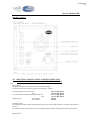
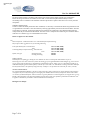
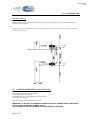
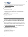
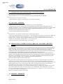
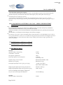
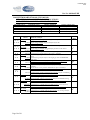
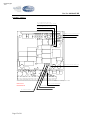
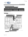
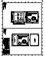
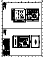
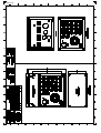
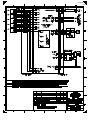
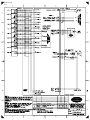
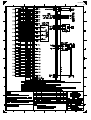
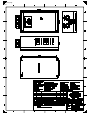
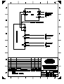
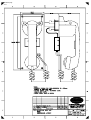
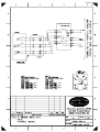
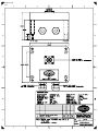
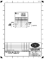
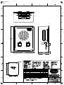
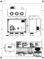
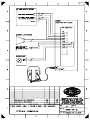
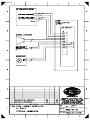
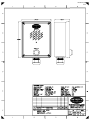
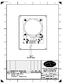
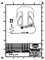
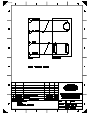
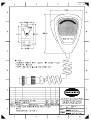
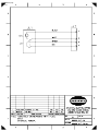
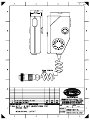
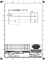
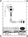
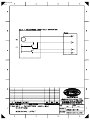
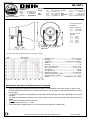
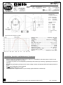
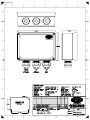
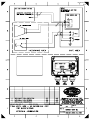
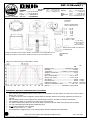
DOCUMENTATION HANDBOOK PHONTECH CIS 3100 / 3101 / 3102 COMMAND INTERCOM SYSTEM www.jotron.com CIS 310X Handbook contents: SYSTEM / MASTER STATIONS: COMMAND INTERCOM SYSTEM 310X Handbook page: System Description ……...…………………………………………… 08300-007-DE Mechanical Layout, 3100, Master Station 5L ..........................…..… 08300-001-ML Mechanical Layout, 3101, Master Station 10L ..........................…..… 08300-002-ML Mechanical Layout, 3102, Master Station 20L ..........................…..… 08300-003-ML External Connection , 3100, Master Station 5L …...........................… 97301-007-EC External Connection , 3101, Master Station 10L ….........................… 97301-002-EC External Connection , 3102, Master Station 20L ….........................… 97301-013-EC .………… .........…… .........…… .........…… ..........…… ..........…… ..........…… 3 19 20 21 22 23 24 Mechanical Layout …........................….………….……………….. 99900-001-ML .………… Internal wiring / External Connection ….....………………………… 99900-001-IW ..………… 25 26 SYSTEM / MASTER STATION SUPPORT UNITS: 9014, GENERAL PURPOSE BACKUP POWER SUPPLY 0019, LINE AMPLIFIER Mechanical Layout …..........................…………….……………….. 88000-004-ML .………… Internal wiring / External Connection ….....………………………… 88000-004-IW ..………… 27 28 0012, BRIDGE WING MICROPHONE UNIT Mechanical Layout …..........................…………….……………….. 87000-035-MD .………… Internal wiring / External Connection ….....………………………… 87000-035-IW ..………… 29 30 9018, IN-BRIDGE WING UNIT Mechanical Layout …..........................…………….……………….. 97900-000-ML .………… Internal wiring / External Connection ….....………………………… 97900-000-IW ..………… 31 32 0013, BRIDGE WING PLUGBOX FOR MIC./L.S. Mechanical Layout …..........................…………….……………….. 87000-036-ML .………… External Connection …................................………………………… 87000-036-EC ..………… 33 34 SUBSTATIONS: 9001, CABIN SUBSTATION Mechanical Layout …........................….………….……………….. 09908-001-ML .………… External Connection …................................………………………… 09908-001-EC ..………… 35 36 9003, SUBSTATION FOR HEADSET Mechanical Layout …........................….………….……………….. 09908-011-ML .………… External Connection …................................………………………… 09908-011-EC ..………… 37 38 9004, CALL UNIT Mechanical Layout …........................….………….……………….. 09908-003-ML .………… External Connection …................................………………………… 09908-003-EC ..………… 39 40 9009, SUBSTATION FOR PORTABLE LOUDSPEAKER Mechanical Layout …........................….………….……………….. 09908-004-ML .………… External Connection …................................………………………… 09908-004-EC ..………… 41 42 0010, PORTABLE LOUDSPEAKER w/BRACKET Mechanical Layout …........................….………….……………….. 87000-022-ML .………… Internal wiring / External Connection ….....………………………… 87000-022-IW ..………… 43 44 9011, PLUGBOX WEATHERPROOF Mechanical Layout …........................….………….……………….. 09908-005-ML .………… External Connection …................................………………………… 09908-005-EC ..………… 45 46 9016, SUBSTATION Mechanical Layout …........................….………….……………….. 09908-012-ML .………… External Connection …................................………………………… 09908-012-EC ..………… 47 48 9135, HANDSET SUBSTATION w/RELAY Mechanical Layout …........................….………….……………….. 08900-001-ML .………… Mechanical Layout (wall mounting) .….………….……………….. 08900-001-ML-02 ...…… External Connection …................................………………………… 08900-001-EC ..………… 49 50 51 9052, SUBSTATION, WATERTIGHT Mechanical Layout …........................….………….……………….. 02900-005-ML .………… Ver. 2011.04 52 External Connection …................................………………………… 02900-005-EC ..………… 53 ACCESSORIES: 0005, HEADSET Mechanical Layout …........................….………….……………….. 87000-027-ML .………… Internal wiring / External Connection ….....………………………… 87000-027-IW ..………… 54 55 9017, HANDHELD MICROPHONE w/PLUG Mechanical Layout …........................….………….……………….. 96900-017-ML .………… Internal wiring / External Connection ….....………………………… 96900-017-IW ..………… 56 57 9117, 2 WAY MICROPHONE FOR BRIDGE WING Mechanical Layout …........................….………….……………….. 96900-018-ML .………… Internal wiring / External Connection ….....………………………… 96900-018-IW ..………… 58 59 9217, WATERPROOF HAND-HELD MICROPHONE Mechanical Layout …........................….………….……………….. 96900-019-ML .………… Internal wiring / External Connection ….....………………………… 96900-019-IW ..………… 60 61 HP-10, HORN LOUDSPEAKER 10W, IP-56 Data Sheet …........................….………….……………….................................................………… 62 HP-15, HORN LOUDSPEAKER 15W, IP-56 Data Sheet …........................….………….……………….................................................………… 63 HP-20, HORN LOUDSPEAKER 20W, IP-67 Data Sheet …........................….………….……………….................................................………… 64 EX SUBSTATIONS & ACCESSORIES: 9041, EX INTERFACE UNIT FOR SUBSTATIONS Mechanical Layout …........................….………….……………….. 09908-006-ML .………… External Connection …................................………………………… 09908-006-EC ..………… 65 66 0043, EXTERNAL LOUDSPEAKER INTERFACE Mechanical Layout …........................….………….……………….. 94000-003-ML .………… Internal wiring / External Connection ….....………………………… 94000-003-IW ..………… 67 68 GHG-411, CALL UNIT (EX) Mechanical Layout …........................….………….………………...................................………… 69 DSP-15EExmN, EX HORN LOUDSPEAKER, IP-67 Data Sheet …........................….………….……………….................................................………… 70 Handbook page 3/71 Doc.No.: 08300-007-DE 0 REV No: 081027 ISSUE DATE FINAL DOKUMENTATION REASON FOR ISSUE CD PREPARED CHECKED APPROVED TITLE: CIS SYSTEMS MASTER STATION SERIES 310X VERSION 05827 Description / Beskrivelse This document is the property of PHONTECH and must not be copied or shown to a third person without our written acceptance. In the interest of product improvement, PHONTECH reserves the right to alter specification and design without notice. SIZE: NA DOC no: 08300-007-DE FILE NAME: Page 1 of 16 UED no: 94 08300-007-DE.doc Handbook page 4/71 Doc.No.: 08300-007-DE CONTENTS. 1.0 INTRODUCTION / INTRODUKSJON 2.0 GENERAL DESCRIPTION / GENERELL BESKRIVELSE 3.0 FACILITY LIST / FUNKSJONER OG MULIGHETER 4.0 MOUNTING / INSTALLATION / SCREEN CONNECTION. MONTERING / INSTALLASJON OG SKJERM TERMINERING 5.0 CABLE REQUIREMENTS / KRAV TIL KABEL 6.0 SELECTIVE CALLS / SELEKTIVE ANROP 7.0 ALL CALL / ALLEKALL(FELLESANROP) 8.0 BRIDGE WING - EXTERNAL PAGING BROVING - EKSTERNT AKTIVERT ANROP 9.0 PRIORITY / PRIORITET 10.0 CALLS DURING AN EXTERNAL ALL-CALL ANROP UNDER EKSTERNT ALLEKALL 11.0 INTENTIONALLY LEFT OUT / UTELATT 12.0 INTENTIONALLY LEFT OUT / UTELATT 13.0 TECHNICAL DATA / TEKNISKE DATA 14.0 SYSTEM BOARD 97301-001 (CIS 3100/3101) STRAPPING AND CONNECTION POINT LOCATIONS. LOKALISERING AV LINKER OG KONTAKTPUNKTER 15.0 SYSTEM BOARD 97301-011 (CIS 3102) STRAPPING AND CONNECTION POINTS LOCATION. LOKALISERING AV LINKER OG KONTAKTPUNKTER Page 2 of 16 Handbook page 5/71 Doc.No.: 08300-007-DE 1.0 INTRODUCTION / INTRODUKSJON Eng.: A command intercom system (CIS) consist of one MASTER station (3100 series), most often located on the ships bridge, and distributed SUBSTATIONS (9000 series) in cabins, engine room, engine control room a.s.o. The CIS may also comprise port and starboard side BRIDGE WING stations. The CIS may also be interconnected with the PHONTECH small public address and alarm system (SPA). The CIS serves as two-way command and intercom system. The communication channels is to/from the master station and the substations. Please note that communication between the substations is not possible. The compact design makes the CIS easy to install. The mounting is for 3100/3101 DIN 144 x 144mm, 3102 DIN 192 x 144 mm. flush mounting, or wall mounting. (wallmount backbox required) No.: Et kommando intercom system (CIS) består av en MASTER stasjon (3100 serie), som oftest plassert på båtens bro, og distribuerte understasjoner (9000 serie) i lugarer, motorrom, motor kontrollrom osv. CIS kan også omfatte babord og styrbord broving stasjoner. Systemet kan også tilkobles til PHONTECH "small public address and alarm system" (SPA). CIS tjener som et to-veis kommando kommunikasjonssystem, med oppkallsmulighet begge veier. Kommunikasjonen går mellom master og understasjoner, dvs. at kommunikasjon mellom understasjoner ikke er mulig. Det kompakte designet gjør systemet lett å installere. Montering er for 3100/3101 DIN 144 x 144mm, 3102 DIN 192 x 144 mm. innfelt montering eller på vegg montasje. ting. Veggmontering krever ekstra bakboks som er ekstrautstyr. 2.0 GENERAL DESCRIPTION / GENERELL BESKRIVELSE Eng.: The CIS is delivered as follows: MASTER STATIONS - 3100 CIS MASTER STATION max. 5 extensions. Amplifier capacity 10W. - 3101 CIS MASTER STATION max. 10 extensions. Amplifier capacity 20W. - 3102 CIS MASTER STATION max. 20 extensions. Amplifier capacity 40W. SUBSTATIONS, ACCESSORIES - 9001 substation for cabins and/or accommodation areas. - 9003 substation for headset with relay. - 9004 call unit for loudspeaker, weatherproof. - 9009 call unit for portable loudspeaker, weatherproof. - 9011 plug box, weatherproof. - 9016 call unit for loudspeaker, loudspeaker on/off switch, weatherproof. - 0035 engine control room phone. (handset) - 0005 headset 10 m. cable and plug. - 0006 additional handset. - 0010 portable loudspeaker cable and plug. - 0012 gooseneck microphone unit, PTT, flush mounting. - 0013 microphone box, bridge wing connection. - 0017 hand microphone cable and plug. - 0019 line amplifier. The MASTER stations contains the electronics required in an CIS. As an extended value added feature, the CIS 310X units are supplied with a "loudspeaker as substation / automatic call disable" facility. This makes the installer able to connect plain loudspeakers directly as substations. During power on the CIS 310X unit will detect such configurations and prevent calls from this positions. No.: Page 3 of 16 Handbook page 6/71 Doc.No.: 08300-007-DE CIS leveres som følger: MASTER STASJONER: - 3100 CIS MASTER STASJON maks. 5 linjer. Forsterker kapasitet 10 W. - 3101 CIS MASTER STASJON. maks. 10 linjer. Forsterker kapasitet 20 W. - 3102 CIS MASTER STASJON. maks. 20 linjer. Forsterker kapasitet 40 W. UNDERSTASJONER/UTSTYR: - 9001 understasjon for lugar/ oppholdsrom. - 9003 understasjon for hodesett med rele. - 9004 oppkallsenhet for høyttaler, værsikker. - 9009 kalleenhet for bærbar høyttaler, værsikker. - 9011 plugg boks værsikker. - 9016 kalleenhet for høyttaler, høyttaler bryter, værsikker. - 0035 maskinkontroll rom telefon. (håndsett) - 0005 hodesett med 10m kabel og plugg. - 0006 ekstra handsett. - 0010 bærbar høyttaler,med kabel og plugg. - 0012 svanehals mikrofon enhet, tal knapp, innfelt montering. - 0013 mikrofonboks for broving tilkobling. - 0017 håndmikrofon med kabel og plugg. - 0019 linjeforsterker. MASTER stasjonene inneholder stort sett all elektronikken som kreves i et CIS system. I tillegg er alle CIS 310X enheter utstyrt med funksjonen "høyttaler som understasjon / automatisk oppkalls-hindring. Dette gir installatøren mulighet til å tilkoble høyttalere direkte til understasjon linjer. Ved påslag vil CIS 310X enheten oppdage dette og i ettertiden hindre oppkall fra disse posisjonene. 3.0 FACILITY LIST Eng.: (see figure 1) CIS 3100: - Connection for 5 substation lines. CIS 3101: - Connection for 10 substation lines. CIS 3102: - Connection for 20 substation lines. COMMON: - Loudspeaker as substation / automatic call disable - Connection for port and starboard bridge wing stations. - Connection for phonTECH SPA system. - Built-in wide-band loudspeaker. - Built- in condenser microphone. - Automatic gain control for speech level. - Loudspeaker volume control - Bi-coloured key indicator leds. - Call key. - Talk key. - Automatic all call function. - Extra signal organ output for line 1-4. Page 4 of 16 Handbook page 7/71 Doc.No.: 08300-007-DE - External loudspeaker output connections. OPTIONS. - Line engagement time out. - Optional extra signal organ output for all lines (up to 10) - Optional line amplifier connection. - Gooseneck/handheld microphone connection. No.: CIS 3100: - Tilkobling for 5 understasjoner. CIS 3101: - Tilkobling for 10 understasjoner. CIS 3102: - Tilkobling for 20 understasjoner. FELLES: - Høyttaler som biapparat / automatisk oppkalls-hindring - Tilkobling for babord og styrbord broving stasjoner. - Tilpasset for sammenkobling med phonTECH SPA system. - Innebygget bredbånds høyttaler. - Innebygget kondensator mikrofon. - Automatisk nivå kontroll krets for tale. - Høyttaler volum kontroll. - To-fargede linje indikasjons lysdioder. - Kalle tast. - Tale tast. - Automatisk allekall funksjon. - Ekstra signal giver utgang for linje 1-4. - Ekstern høyttaler utgang. VALGBART: - Automatisk tidsstyrt linje nedkobling - Ekstra signal utgang for alle linjer. (opp til 10) - Linje forsterker tilkobling. - Svanehals /håndmikrofon tilkobling Page 5 of 16 Handbook page 8/71 Doc.No.: 08300-007-DE FIGURE 1 / FIGUR 1 4.0 MOUNTING / INSTALLATION / SCREEN CONNECTION MONTERING / INSTALLASJON OG SKJERMTERMINERING Eng.: MOUNTING: The master stations 3100/3101/3102 is delivered for flush mounting. On request the units may be delivered with wall-mounting box. (option) Front plate dimensions 3100 and 3101: 3102: Cut- out dimensions for flush-mounting 3100 and 3101: 3102: Depth, all types flush mounted: wall mounted: 144 x 144 mm. (HxW) 144 x 192 mm. (HxW) 115 x 115 mm. (HxW) 115 x 163 mm. (HxW) 100 mm. 100 mm. INSTALLATION: The installation should be planned in details before starting. The cables should be listed in a cable plan, with number of pairs a.s.o. The location of each unit in the intercom system should be planned to obtain maximum performance and user ability. Page 6 of 16 Handbook page 9/71 Doc.No.: 08300-007-DE The master station location/ orientation with regards to the operator must be taken especially into consideration. Please note the gooseneck mic (if installed) is "close talk". A close talk microphone has the ability to reduce surrounding noise to a minimum. The drawback is that the operator has to speak no more than 5-10 cm away from the microphone. SCREEN CONNECTION. In order to obtain maximum performance after installation, it is necessary to terminate the cables and ground the screens in a good manners. The cables is to be de-isolated by removing approximately 250 mm of the outer insulation. Then the screen braid is cut off appr. 30 mm longer than the outer isolation. The conductors is de-isolated and fitted with endcrimps before they are inserted into the terminal. The outer screen is clamped to the cable fixing arcs inside the cabinet. Cable ties of a conductive type is recommended for best result. Please see figure 2 for more details. No.: Hoved stasjonene 3100/3101/3102 leveres som standard for innfelt montering. På forespørsel kan veggboks leveres for utvendig montering Front plate dimensjoner 3100 and 3101: 3102: Utstansingsmål for innfelt montering, 3100 and 3101: 3102: Dybde, alle typer innfelt montering: utvendig montering: 144 x 144 mm. (HxB) 144 x 192 mm. (HxB) 115 x 115 mm. (HxB) 115 x 163 mm. (HxB) 100 mm. 100 mm. INSTALLASJON: Installasjonen bør planlegges i detalj før start. Kablene bør listes i en kabel plan med nummererte par etc. Plasseringen av hver enhet i intercom systemet bør kartlegges for å oppnå maksimal bruksvennlighet og ytelse. Det bør legges spesiell vekt på plassering av hovedstasjon i forhold til operatøren. Viktig å vite er at dersom det installeres en svanehals mikrofon (gooseneck microphone) er denne ofte "close-talk", dvs. med direktiv virkning. En direktiv mikrofon har den fordel at den er lite følsom for omgivelsesstøy. Ulempen er at operatøren må svært nær for å tale (5-10 cm). SKJERM TERMINERING: For å oppnå maksimal lydkvalitet er det meget viktig med god og riktig terminering av skjerm. Kablene skal avisoleres ved å fjerne den yttre beskyttelses kappen i en lengde på ca 250mm. Deretter kuttes ytterskjermen slik at denne stikker ca. 30 mm ut fra kabelisolasjonen. Lederne avisoleres og helst påmonteres termineringshylser for å oppnå best og varig kontakt i skruterminalene. Ytterskjermen klemmes inntil de dertil egnede feste punktene på innsiden av bakboksen. For å oppnå best kontakt bør festebånd av elektrisk ledende materiale benyttes. Ref. figur 2 for detaljer Page 7 of 16 Handbook page 10/71 Doc.No.: 08300-007-DE FIGURE 2 / FIGUR 2 Eng.: The cable outer screens is to be terminated as shown. Conductive type of cable ties is recommended to obtain best possible screen connections. No.: Kabelens ytterskjerm skal termineres som vist. Festebånd av ledende materiale bør benyttes for å oppnå best kontakt mellom skjerm og chassis. 5.0 CABLE REQUIREMENTS / KRAV TIL KABEL Eng.: To substations: one pair, twisted, outer screen. If extra signal organ: one pair extra. To bridge wings: two pairs, individually twisted, outer screen. Power cables: one pair, gnd. Minimum conductor area all cable types: 0.75 mm2. IMPORTANT: TO SECURE UN-INTERFERED OPERATION DO NOT COMBINE SIGNAL CABLES WITH OTHER CABLE TYPES SUCH AS MAINS SUPPLY. THE CABLING FOR THE CIS SYSTEM SHOULD BE A SEPARATE NETWORK. Page 8 of 16 Handbook page 11/71 Doc.No.: 08300-007-DE Consult drawings 97301-007-EC (CIS 3100), 97301-002-EC (CIS 3101) and 97301-013-EC (CIS 3102) for further cabling information. No.: Til understasjoner: ett par revolvert, utvendig skjermet. Ved ekstra signal organ: et ekstra par. Til broving: to par, individuelt revolvert, utvendig skjerm. Kraft kabler: ett par, jord. Minimum tverrsnitt alle typer: 0,75 mm2. VIKTIG: FOR Å SIKRE UFORSTYRRET DRIFT, IKKE KOMBINER SIGNAL KABLER MED KABLER FOR ANNET UTSTYR SOM F.EKS. NETTKABLER OSV. KABLINGEN FOR CIS SYSTEMET SKAL VÆRE ET EGET NETT. I dokumentene 97301-007-EC (CIS 3100), 97301-002-EC (CIS 3101) og 97301-013-EC (CIS 3102) finnes ytterligere informasjon. 6.0. SELECTIVE CALLS / SELEKTIVE ANROP Eng.: This chapter describes the operation of the CIS master stations. In idle status / after power-up, the master station line indicator leds illuminates dim green as night orientation light. No.: Dette kapittelet beskriver bruken av hovedstasjonene. I hvilestilling og etter påslag lyser hovedstasjonens lysdioder svakt grønt . (bakbelysning) 6.1. MASTER CALL TO A SUBSTATION / HOVEDSTASJON ANROPER UNDERSTASJON Eng.: - Select the line by operating the appropriate line key. The line indicator led turns red. - Now press the CALL key. This will generate an attention tone in the substation unit loudspeaker and activate the extra signal device if any. Note: several lines may be called simultaneously. No.: - Velg ønsket linje ved å trykke inn linjeknappen. Linje indikator lysdiode skifter til rødt fullt lys. - Trykk CALL knappen. Dette starter en oppmerksomhetstone i understasjonens høyttaler/ hodesett. Eventuelt ekstra signal organ starter også. NB: flere linjer kan kalles samtidig. 6.2. MASTER CALL TO ALL SUBSTATIONS / HOVEDSTASJON ANROPER ALLE UNDERSTASJONER Eng.: - Press the ALL/TALK key without any lines engaged. The master station automatically enters the all-call mode. All the leds illuminates red colour. -Speak into the microphone. No.: - Trykk ALL/TALK knappen uten noen linjer aktive. Hovedstasjonen velger automatisk alle-kall modus. Alle lysdiodene tenner rødt lys, også lysdiode for ALL/TALK knappen. -Snakk direkte inn i mikrofonen. Page 9 of 16 Handbook page 12/71 Doc.No.: 08300-007-DE 6.3 A SUBSTATION ANSWER THE CALL FROM THE MASTER / UNDERSTASJONEN SVARER PÅ ANROP FRA HOVEDSTASJON Eng.: When the attention tone is heard in the loudspeaker and / or the extra signal organ is activated: - Press the talk-key and answer the call. - Keep the TALK key pressed all time during the conversation. No.: Når oppmerksomhetstonen høres i høyttaleren / eller ekstra signal giver aktiveres: - Trykk på TALK knappen for å svare oppkallet. - Hold TALK knappen inne hele tiden mens samtalen pågår. 6.3. THE MASTER TALKING TO THE SUBSTATION / HOVEDSTASJONEN SNAKKER TIL EN UNDERSTASJON Eng.: When the call is answered: - Operate the TALK key on the master and talk into the microphone / loudspeaker. - Release the talk-key to return to listen-mode. No.: Når understasjonen svarer oppkallet: - Trykk TALK knappen og snakk inn i mikrofonen / høyttaleren. - Slipp TALK knappen for å returnere til lytte-modus. 6.5. SUBSTATION CALL TO MASTER / UNDERSTASJON OPPKALL TIL HOVEDSTASJON Eng.: - Press the CALL button on the substation / call unit. This generates an attention tone in the master station as long as the call-button is kept pressed. Simultaneously the appropriate line indicator led turns full light green to indicate which substation made the call. Note: If a call occurs during an on-going conversation, the attention tone is disabled, but the line indicator led change to green colour full intensity. No.: - Trykk på CALL knappen på understasjonen. Dette starter oppkallstonen i hovedstasjonen, og denne lyder så lenge understasjonen prøver å kalle opp. Samtidig tenner linjens lysdiode grønn, fullt lys, for å indikere hvilken understasjon som kaller. Viktig: hvis et oppkall inntreffer under pågående samtale, aktiveres ikke kalletonen, men lysdioden tenner fullt grønt lys. 6.6. THE MASTER ANSWER THE CALL FROM A SUBSTATION / HOVEDSTASJONEN SVARER PÅ ANROP FRA UNDERSTASJONEN Eng.: To answer the call from a substation: - Press the appropriate line key. The line indicator led turns green full intensity. - Press the talk key and speak into the microphone. - Release the TALK key to return to listen mode. No.: For å svare et oppkall fra en understasjon. - Trykk inn gjeldende linjeknapp. Lysdioden tenner fullt rødt lys. - Trykk inn TALK knappen og snakk inn i mikrofonen. - Slipp TALK knappen for å returnere til lytte-modus. Page 10 of 16 Handbook page 13/71 Doc.No.: 08300-007-DE 6.7. TERMINATING THE CONVERSATION / AVSLUTTE SAMTALEN Eng.: The conversation is terminated by de-activating the line: - Operate the line key once more. The line indicator led turn green half-light intensity. (backlight) No.: Samtalen avsluttes ved å legge linjen ut igjen: - Trykk linjeknappen en gang til. Lysdioden skifter til grønt baklys (hvilestilling). 7.0. ALL CALL / ALLEKALL Eng.: The master station CIS 3100/3101/3102 may perform an ALL CALL to the substations. - Operate the ALL/TALK key. (no lines active) A special attention tone (1kHz chopped) is distributed to all the substations for about 2-3 seconds. Simultaneously all the extra signal organ outputs is activated for 2-3 seconds. All the line indicator leds turns red colour. The call key indicator led illuminate red during this interval (2-3 seconds.) When this led turns off again the system is ready to use. - Give the message and release the ALL/TALK key. No.: Hovedstasjonene CIS 3100/3101/3102 kan utføre alle kall til understasjonene. - Trykk inn ALL/TALK knappen når hovedstasjonen er i hvilestilling (ingen linjer aktivert). En spesiell tone 1kHz pulset (viktig melding), distribueres til alle understasjonene i cirka. 2-3 sekunder. Samtidig aktiveres alle ekstra signal utganger i cirka 2-3 sekunder. Alle linje indikator lysdioder tenner rødt. Call knappens lysdiode tenner rødt i 2-3 sekunder. Når CALL knappens lysdiode slukker er systemet klart til bruk. - Snakk inn i mikrofonen og slipp TALK knappen etter meldingen. 8.0 BRIDGE WING - EXTERNAL PAGING / BROVING - EKSTERNT AKTIVERT ANROP Eng.: Two separate external audio and key lines are provided for remote paging. These interfaces are as default intended for bridge wing paging, port and starboard. In this mode they interface a loudspeaker/microphone/key configuration. The paging can be done in 2 ways. Either prepared in advance on the master station making the bridge wing able to communicate with the selected substations (conversation mode). Or the system can be keyed directly from idle into the all call paging mode. In both situations the master station loudspeaker will relay the activity. The starboard bridge wing interface has an alternative mode; the emergency allcall mode. It can be redefined as an interface to other equipment (Phontech SPA 1500 system) or be activated from an emergency microphone position. In the emergency all call mode it will generate an ALL CALL situation independent of prior status (idle or busy) (Ref. chapter 9 - priority and chapter 14 or 15 - Strapping and connection point locations). Both speech audio and alarms may be fed to this input. No.: To separate eksterne audio og nøklings linjer er tilgjengelig for fjernstyring av anrop. Disse linjene er primært ment brukt til anrop fra broving , babord og styrbord. Linjene interfacer en høyttaler/mikrofon/nøklings konfigurasjon. Anropet kan gjøres på 2 måter. Enten kan et linjevalg settes opp i forkant. På denne måten kan brovingene samtale med understasjonene i begge retninger (konversasjons modus). Eller systemet kan nøkles direkte fra hvilesituasjon til allekall/fellesanrop. I begge tilfelle vil hovedstasjonens høyttaler monitorere samtale begge veier. Styrbord broving linje kan omdefineres til en nød allekall modus. Linjen kan omdefineres for tilkobling enten til annet utstyr (Phontech SPA 1500 system) eller den kan aktiveres fra en nødmikrofon. I nød allekall modus vil systemet generere et allekall/fellesanrop uansett status på forhånd (ledig/opptatt). (ref. kapittel 9 - Prioritet og kapittel 14 eller 15 - Lokalisering av linker og kontaktpunkter). Både tale og alarmtoner kan tilføres denne linjen. 9.0 PRIORITY / PRIORITET Eng.: Page 11 of 16 Handbook page 14/71 Doc.No.: 08300-007-DE - The master station normally has first priority. - If the external emergency paging is enabled this will have an intermediate first priority and override existing calls. After this first priority override activation the master station regains priority and can place calls of any type. No.: - Hovedstasjonen har normalt første prioritet. - Dersom eksternt nød allekall aktiveres vil dette likevel ha midlertidig første prioritet og overstyre eventuelle eksisterende anrop. Etter første gangs aktivering vil hovedstasjonen gjenerobre første prioritet og kan gjøre anrop av alle typer. 10.0 CALLS DURING AN EXTERNAL ALL-CALL / ANROP UNDER EKSTERNT ALLEKALL Eng.: Line selections during emergency all call (press any substation line key even if this is already busy (led indicator) causes all other lines to disable and a two-way conversation can be made. Alternatively the talk key can be activated immediately causing substation audio to be replaced by the master station message. When the talk key is released, the external emergency all call will be re-engaged. No.: Dersom linjer velges under et eksternt nød allekall (aktiver understasjon linjer selv om linjeindikatoren lyser rødt) vil de øvrige linjene deaktiveres slik at en to-veis samtale med valgt linje fan skje. Alternativt kan hovedapparat operatøren trykke TALK direkte og erstatte understasjon audio med egen melding. Når TALK tasten slippes gjeninnføres det eksterne nød allekall. 11.0 INTENTIONALLY LEFT OUT / UTELATT 12.0 INTENTIONALLY LEFT OUT / UTELATT 13.0 TECHNICAL DATA. CIS 3100. Operation voltage / driftsspenning: Current drain / strømtrekk: 24 VDC 1 A max. Line capacity / linjekapasitet: Power amp. capacity / forsterkerkapasitet: 5 lines. 10 W total Up to 10 W per line. Frequency range / frekvens område: Distortion / forvrengning: Better than 400-6000 Hz (-3dB) Better than 2.5% typ. Extra signal organ output / ekstra signal giver utgang: + 24 VDC, max 150mA Open collector output to GND Bridge wing microphone input / Broving mikrofon nivå: Bridge wing loudspeaker output / Broving høyttaler utgang: 200 Ohm / 10 mV typ. 8 Ohm / 5W typ. Line level, Stb. Bridge wing Emergency paging level / Linje nivå, Styrbord broving Nød melding nivå: 775 mV (0dBm) typ. CIS 3101. Operation voltage / driftsspenning: 24 VDC Page 12 of 16 Handbook page 15/71 Doc.No.: 08300-007-DE Current drain / strømtrekk: 2 A max. Line capacity / linjekapasitet: Power amp. capacity / forsterkerkapasitet: 10 lines. 20 W total Up to 10 W per line. Frequency range / frekvens område: Distortion / forvrengning: Better than 400-6000 Hz (-3dB) Better than 2.5% typ. Extra signal organ output / ekstra signal giver utgang: + 24 VDC, max 150mA Open collector output to GND Bridge wing microphone input / Broving mikrofon nivå: Bridge wing loudspeaker output / Broving høyttaler utgang: 200 Ohm / 10 mV typ. 8 Ohm / 5W typ. Line level, Stb. Bridge wing Emergency paging level / Linje nivå, Styrbord broving Nød melding nivå: 775 mV (0dBm) typ. CIS 3102 Operation voltage / driftsspenning: Current drain / strømtrekk: 24 VDC 3 A max. Line capacity / linjekapasitet: Power amp. capacity / forsterkerkapasitet: 20 lines. 40 W total Up to 10 W per line. Frequency range / frekvens område: Distortion / forvrengning: Better than 400-6000 Hz (-3dB) Better than 2.5% typ. Extra signal organ output / ekstra signal giver utgang: + 24 VDC, max 150mA Open collector output to GND Bridge wing microphone input / Broving mikrofon nivå: Bridge wing loudspeaker output / Broving høyttaler utgang: 200 Ohm / 10 mV typ. 8 Ohm / 5W typ. Line level, Stb. Bridge wing Emergency paging level / Linje nivå, Styrbord broving Nød melding nivå: 775 mV (0dBm) typ. Page 13 of 16 Handbook page 16/71 Doc.No.: 08300-007-DE 14.0 SYSTEM BOARD 97301-001 (CIS 3100/3101) STRAPPING AND CONNECTION POINT LOCATIONS / LOKALISERING AV LINKER OG KONTAKTPUNKTER. J2 Terminal / pin No. - J2 Terminal / pin. nr. 1&2 3&4 5&6 7&8 Strap ST2 ST1 y y---y ST2 ST1 y---y y ST3 y y ST3 y---y ST4 y y ST4 Condition Tilstand ST1 closed ST2 open ST1 lukket ST2 åpen ST1 open ST2 closed ST1 åpen ST2 lukket ST3 open ST3 åpen ST3 closed ST4 closed ST4 lukket ST5 open ST5 y y ST5 åpen ST5 closed y---y ST5 lukket ST7 ST6 y y---y ST7 ST6 y---y y Funksjon / tilkoblet utstyr Volum potensiometer Apparat høyttaler Mikrofon element Tale knapp Description / Functionality Beskrivelse / Funksjon Using an additional microphone, the integrated microphone is not used Benytter tilleggsmikrofon, integrert mikrofon benyttes ikke Using the integrated microphone, an additional unit microphone is not mounted Benytter integrert mikrofon, tilleggsmikrofon på enheten er ikke montert Starboard bridge wing interface is used as bridge wing interface - NORMAL Styrbord broving interface benyttes som broving - NORMAL Starboard bridge wing interface is used as input for external PRIORITY ALL CALL ST3 lukket Styrbord broving interface benyttes som inngang for eksternt PRIORITERT ALLE KALL Microcontroller RESET: Always open during normal working conditions ST4 open ST4 åpen Mikrokontroller RESET: Skal alltid være åpen i normal drift y---y ST5 Function / Equipment Volume potensiometer Unit loudspeaker Microphone TALK activator ST6 closedST7 open ST6 lukketST7 åpen ST6 openST7 closed ST6 åpenST7 lukket Page 14 of 16 Only to be used by service personnel: Always open during normal working conditions Benyttes kun av service personell: Skal alltid være åpen i normal drift Disable loudspeaker audio to the starboard bridge wing interface. This facility is used in line feed conditions. i.e PA-system, PABX etc. Frakoble høyttaler audio til styrbord broving interface. Benyttes ved tilkobling til eksternt nøklingsutstyr f.eks. PA-system, PABX etc. Enable loudspeaker audio to the starboard bridge wing. This facility is used in NORMAL bridge wing operation Tilkoble høyttaler audio til styrbord broving. Benyttes ved NORMAL broving funksjon The starboard bridge wing is connected to a line level (0dBm) interface, i.e. PA system, PABX etc. Styrbord broving er tilkoblet linje nivå (0dBm) interface. F.eks. PA system, PABX etc. The starboard bridge wing is connected to a microphone level interface, i.e. bridge wing microphone, microphone for PRIORITY ALL CALL Styrbord broving er tilkoblet mikrofon nivå interface, f.eks. broving mikrofon, mikrofon for PRIORITERT ALLE KALL Standard Handbook page 17/71 Doc.No.: 08300-007-DE FIGURE 3 / FIGUR 3 ST 3 PROGRAM SELECTOR NORM OPEN CLOSED WHEN STB BW INPUT IS USED F. ALLCALL ST1 CLOSED WHEN EXT. MIC. IS USED ST2 CLOSED WHEN INTERNAL MIC IS USED CONNECTION PIN 7/8 FOR EXT. MIC PTT CONNECTION PIN 5/6 FOR EXT. MIC 1 ST2 ST1 ST3 1 + ST5 ST7ST6 ST4 + + MICROCONTROLLER RESET ALWAYS OPEN + + + + + 1 file:\..\strapbes.drw PHONTECH 97301-001.MK.1. SEEN FROM COMPONENT SIDE GENERAL VOLUME POTENSIOMENTER CLOSED WHEN STB BW INPUT IS 0 dBm CLOSED WHEN STB BW INPUT IS 5mV ST5: NORMAL BRIDGEWING: CLOSED Page 15 of 16 Handbook page 18/71 Doc.No.: 08300-007-DE 15.0 SYSTEM BOARD 97301-011 (CIS 3102) STRAPPING AND CONNECTION POINTS LOCATION / LOKALISERING AV LINKER OG KONTAKTPUNKTER. J3 Terminal / pin No. - J3 Terminal / pin. nr. 1&2 3&4 5&6 7&8 Function / Equipment Volume potensiometer Unit loudspeaker Microphone TALK activator Funksjon / tilkoblet utstyr Volum potensiometer Apparat høyttaler Mikrofon element Tale knapp Ref. strap descriptions under chapter 14.0 Ref. link beskrivelser under kapittel 14.0 FIGURE 4 / FIGUR 4 ST 3 PROGRAM SELECTOR NORM OPEN CLOSED WHEN STB BW INPUT IS USED F. ALLCALL CONNECTION PIN 7/8 FOR EXT. MIC PTT ST1 CLOSED WHEN EXT. MIC. IS USED CONNECTION PIN 5/6 FOR EXT. MIC ST2 CLOSED WHEN INTERNAL MIC IS USED M18 M19 C27 J7 R58 R59 R60 R61 R66 R67 R68 R167 R164 R165 R161 R163 R162 R160 R159 R157 R158 R156 R155 R154 R151 R153 R152 J3 C45 R57 M128 C43 R56 M126 M129 1 M17 R72 ST2 ST1 ST3 RE107 RE106 R149 R55 R65 1 M7 RE108 R150 R105 R44 R106 R103 R109 J4 Q6 R64 RE109 RE110 R104 R100 R52 R96 R63 R93 R54 R71 R101 R95 R92 R83 R80 R77 R70 R62 R99 R102 R97 R98 R91 R94 R90 R85 R87 R88 R89 R84 R86 R79 R81 R82 R76 R78 R73 R74 C26 R75 M9 C25 M8 J2 1 J1 R169 R69 1 RE13 M127 C42 C41 RE5 M130 RE112 RE111 RE113 RE115 RE119 RE117 C44 J6 M16 M125 RE12 M5 RE3 RE2 RE1 RE114 C28 RE4 1 RE15 X1 1 M15 M6 RE14 M2 C2 F1 C23 Q4 C3 R16 M20 M3 R107 R11 R17 R18 R19 RE120 + + C37 C39 R20 R108 C32 C7 C8 J5 1 RE118 RE121 C18 R8 + C21 M1 C1 C16 RE116 + M124 R12 R10 + C33 Q1 + + Q2 + C19 M122 M4 + Q3 R2 R3 C13 ST7 M123 + C11 M21 ST5 ST6 + C112 ST4 Q5 + C9 RE11 40 MICROCONTROLLER RESET ALWAYS OPEN PHONTECH 97301-011 SEEN FROM COMPONENT SIDE GENERAL VOLUME POTENSIOMETER CLOSED WHEN STB BW INPUT IS 0 dBm CLOSED WHEN STB BW INPUT IS 5mV ST5: NORMAL BRIDGEWING: CLOSED Page 16 of 16 file:v:\....\strapbes.drw Handbook page 19/71 Handbook page 20/71 Handbook page 21/71 Handbook page 22/71 Handbook page 23/71 Handbook page 24/71 Handbook page 25/71 Handbook page 26/71 Handbook page 27/71 Handbook page 28/71 Handbook page 29/71 Handbook page 30/71 Handbook page 31/71 Handbook page 32/71 Handbook page 33/71 Handbook page 34/71 Handbook page 35/71 Handbook page 36/71 Handbook page 37/71 Handbook page 38/71 Handbook page 39/71 Handbook page 40/71 Handbook page 41/71 Handbook page 42/71 Handbook page 43/71 Handbook page 44/71 Handbook page 45/71 Handbook page 46/71 Handbook page 47/71 Handbook page 48/71 Handbook page 49/71 Handbook page 50/71 Handbook page 51/71 Handbook page 52/71 Handbook page 53/71 Handbook page 54/71 PHONTECH Handbook page 55/71 Handbook page 56/71 Handbook page 57/71 Handbook page 58/71 Handbook page 59/71 Handbook page 60/71 Handbook page 61/71 Handbook page 62/71 HP-10(T) ISO 9001 CERTIFIED N-3770 Kragerø NORWAY Phone: ........ (47) 35 98 56 00 Fax: ............ (47) 35 98 56 10 E-mail: .............. [email protected] Web-site: ....... www.dnh.no DNH WW Ltd. England Phone:….(44) 1908 275 000 Fax:……..(44) 1908 275 100 E-mail:………[email protected] DNH GmbH Germany Phone:…..….(49) 040 6569 30-0 Fax:……...…(49) 040 6569 30-30 E-mail:…………………[email protected] DNH France Phone:……(33) 1 5380 0276 Fax:…….…(33) 1 4588 1594 E-mail:…..…[email protected] DNH Speakers Inc. USA Phone:………….(1) 484 494 5790 Fax:……………..(1) 484 494 5793 E-mail:…[email protected] 70/100 volt Combined Transformer: Primary connections: 5:7 70 Volt line 5:8 100 Volt line Secondary nominal tappings: 1:4 10,0 W 1:3 5,0 W 2:4 3,5 W 1:2 2,5 W 3:4 1,5 W 2:3 0,8 W M20 Cable diameter: 6 - 12 mm Sound pressure levels at different frequencies at 1W/1m sine wave. Material / Color ..................................... ABS / RAL 7035 Mounting ...........................................................Bracket Termination .......................... Internal screw connections Weight ....................................................(2,9 lb) 1,3 kg IP-rating (UL equivalent) ...........................(12 & 4X) 56 Max / min amb temp ................................ 90 °C / -50 °C Rated / max. power ................................... 10 W / 15 W SPL 1W/1m ....................................................... 106 dB SPL rated power ................................................ 116 dB Effective freq. range ............................... 410 – 8000 Hz Dispersion (-6dB) 1kHz / 4kHz ........................150° / 45° Directivity factor, Q (2kHz) ....................................... 7,4 Options ................................. Impedances, colors, labels Installation, Operation and Maintenance Procedures When mounting the loudspeaker please ensure that it is re-assembled in the same manner in which it was received. Fasten the bracket with 1-3 screws and ensure to use all washers in the intended position to assure the IP rating. To change the position of the loudspeaker, please adjust the bracket (by loosening / tightening the screws) as required. For optimum performance, always use the correct voltage / power and operate within the frequency limits as stated. Do not open loudspeaker when energized. Fasten lid with a torque of 1 - 2 Nm. This loudspeaker is supplied with a 2 year warranty against defective materials and workmanship. DNH reserves the right to alter specifications without notice. \\ntserver2\d$\DataArk_2000\DOC-format\HORN\HP10T_ plastic bracket.doc Rev. 16.10.2008 Handbook page 63/71 ISO 9001 CERTIFIED HP-15(T) N-3770 Kragerø NORWAY Phone: ........ (47) 35 98 56 00 Fax: ............ (47) 35 98 56 10 E-mail: .............. [email protected] Web-site: ....... www.dnh.no DNH WW Ltd. England Phone:….(44) 1908 275 000 Fax:……..(44) 1908 275 100 E-mail:………[email protected] DNH GmbH Germany Phone:…..….(49) 040 6569 30-0 Fax:……...…(49) 040 6569 30-30 E-mail:…………………[email protected] DNH France Phone:……(33) 1 5380 0276 Fax:…….…(33) 1 4588 1594 E-mail:…..…[email protected] DNH Speakers Inc. USA Phone:………….(1) 484 494 5790 Fax:……………..(1) 484 494 5793 E-mail:…[email protected] 50/100 volt Combined Transformer: Primary connections: 5:6 50 Volt line 5:8 100 Volt line Secondary nominal tappings: 1:4 15,0 W 1:3 7,5 W 2:4 5,0 W 1:2 4,0 W 3:4 2,0 W 2:3 0,8 W Sound pressure levels at different frequencies at 1W/1m sine wave Material / Color .......................................... ASA / RAL 7035 Mounting ................................................................Bracket Termination .................................. Inside screw connections Weight .................................................................... 1,7 kg IP-rating ........................................................................ 56 Max. / min. amb. temp .................................. 90 °C / -50 °C Rated / max. power ........................................ 15 W / 20 W SPL 1W/1m............................................................. 108 dB SPL rated power ..................................................... 118 dB Effective freq. range ..................................... 330 – 8000 Hz Dispersion (-6dB) 1kHz / 4kHz .............................130° / 35° Directivity factor, Q (2kHz) ............................................ 8,3 Options ...................................... Impedances, colors, labels Installation, Operation and Maintenance Procedures When mounting the loudspeaker please ensure that it is re-assembled in the same manner in which it was received. Fasten the bracket with 1-3 screws and ensure to use all washers in the intended position to assure the IP rating. To change the position of the loudspeaker please adjust the bracket (by loosening / tightening the screws) as required. For optimum performance, always use the correct voltage / power and operate within the frequency limits as stated. Do not open loudspeaker when energized. Fasten lid with a torque of 1 - 2 Nm. This loudspeaker is supplied with a 2 year warranty against defective workmanship. DNH reserves the right to alter specifications without notice. \\ntserver2\d$\DataArk_2000\DOC-format\HORN\HP15T_plastic bracket.doc Rev.16.10.2008 Handbook page 64/71 HP-20(T) 44 ISO 9001 CERTIFIED N-3770 Kragerø NORWAY Phone: ........ (47) 35 98 56 00 Fax: ............ (47) 35 98 56 10 E-mail: .............. [email protected] Web-site: ....... www.dnh.no DNH WW Ltd. England Phone:….(44) 1908 275 000 Fax:……..(44) 1908 275 100 E-mail:………[email protected] DNH GmbH Germany Phone:…..….(49) 040 6569 30-0 Fax:……...…(49) 040 6569 30-30 E-mail:…………………[email protected] DNH Speakers Inc. USA Phone:………….(1) 484 494 5790 Fax:……………..(1) 484 494 5793 E-mail:…[email protected] 50/70/100 volt Combined Transformer: Primary connections: 6:7 50 Volt line 6:8 70 Volt line 6:9 100 Volt line Secondary nominal tappings: 1:4 20,0 W 1:3 10,0 W 2:4 6,0 W 1:2 5,0 W 3:4 2,0 W 2:3 1,5 W M20 Cable diameter: 5 - 12 mm 6 = White, 8= Green, 9 = Red 1W/1m sine wave smooth 1/3 octave Material / Color .................................Polyamide / RAL 7035 Mounting ...............................................................Bracket Termination ................................. Inside screw connections Weight ................................................................... 2,5 kg IP-rating....................................................................... 67 Max. / min. amb. temp ............................... 150 °C / -50 °C Rated / max. power ....................................... 20 W / 25 W SPL 1W/1m ........................................................... 110 dB SPL rated power .................................................... 122 dB Effective freq. range .................................... 310 – 8000 Hz Dispersion (-6dB) 1kHz / 4kHz............................ 115° / 30° Directivity factor, Q (2kHz)………………………………………...9,3 Options………………………………..……impedances, colors, labels Installation, Operation and Maintenance Procedures When mounting the loudspeaker please ensure that it is re-assembled in the same manner in which it was received. Fasten bracket with 1-3 screws. To change the position of the loudspeaker please adjust the bracket (by loosening / tightening the screws) as required. For optimum performance, always use the correct voltage / power and operate within the frequency limits as stated. Do not open loudspeaker when energized. Fasten lid with a torque of 2 - 3 Nm. This loudspeaker is supplied with a 2 year warranty against defective workmanship. DNH reserves the right to alter specifications without notice. C:\Users\Terje\Desktop\HP20T_plastic bracket.doc Rev . 19.04.2010 Handbook page 65/71 Handbook page 66/71 Handbook page 67/71 Handbook page 68/71 Handbook page 69/71 Handbook page 70/71 DSP-15 EExmN(T) ISO 9001 CERTIFIED N-3770 Kragerø DNH WW Ltd. NORWAY England Phone: .........(47) 35 98 56 00 Fax:.............(47) 35 98 56 10 E-mail: [email protected] Web-site: ........ www.dnh.no Phone:….(44) 1908 275 000 Fax:……..(44) 1908 275 100 E-mail:………[email protected] DNH GmbH Germany Phone:…..….(49) 040 6569 30-0 Fax:……...…(49) 040 6569 30-30 E-mail:…………………[email protected] DNH Speakers Inc. USA Phone:………….(1) 484 494 5790 Fax:……………..(1) 484 494 5793 E-mail:…[email protected] Transformer: 100 V line Primary nominal tappings: Cores in cable are no. 1-4 1 2 3 1 2 1 : : : : : : 2 3 4 3 4 4 15,0 W 8,0 W 4,0 W 3,0 W 1,5 W 0,8 W 1 = Red, 2=Yellow 3=Green, 4 = Blue 1 x M20 IECEx approved cable gland and 1 x IECEx approved blind plug. Bracket and all outside nuts and screws in stainless steel. Certified by/ Certification Code/ Number: NEMKO / Ex dema IIB + H2 T4 /IECEx NEM 05.0005 Certified by/ Certification code/ Number: NEMKO / Ex dema IIC T4 / IECEx NEM 05.0005 II 2 G D 1W/1m sine wave smooth 1/3 octave IIB+H 2 version IIB Material / Color ...........................Anti-static PA / Black Mounting ....................................................... Bracket Termination ...................... e-chamber, screw terminals Weight w/ transformer .....................................2,2 kg IP-rating............................................................... 67 Max / min amb temp .............................. 55°C / -50°C Rated / max. power ............................... 15 W / 15 W SPL 1W/1m ................................................... 105 dB SPL rated power ............................................ 116 dB Effective freq range ..............................410 – 7000 Hz Dispersion (-6dB) 1kHz / 4kHz..................... 200° / 50° Options ............................. Impedances, colors, labels IIC 102 dB 113 dB 500-6000 105° / 35° Installation, Operation and Maintenance Procedures When mounting the loudspeaker please ensure that it is re-assembled in the same manner in which it was received. Fasten bracket with 1-3 screws. To change the position of the loudspeaker, please adjust the standard bracket (by loosening / tightening the screws) as required. DSP-15 EExmN/T IECEx can be supplied with 3 different bracket systems, according to customer requirements. DSP-15EExmN/T IECEx can be delivered as 25W version with transformer. For optimum performance, always use the correct voltage / power and operate within the frequency limits as stated. Use only certified/specified cable glands and blanking plugs. Do not open loudspeaker when energized. Fasten lid with a torque of 2 - 3 Nm. This loudspeaker is supplied with a 2 year warranty against defective materials and workmanship. DNH reserves the right to alter specifications without notice. \\ntserver2\d$\DataArk_2000\DOC-format\IECEx\DSP15EExmNT_IECex_15W.doc Rev. 14.01.2010 www.jotron.com