1
truction
anu
®
1/3 Horsepower
(continuous
duty)
2/3 Horsepower
(maximum devemoped)
5-Speed, Step Pulley
620 - 3100 R.P.M. Drill Speed Range
1
P
FOR YOUR OWN SAFETY; Read
and foUlow all of the Safety and
Operating Instructions before
Operating this DdH Press.
Customer Helpline
1-800-897-7709
PRease have your Model No.
and SedaR No. availabUe.
Sears,
Roebuck
Part No. OR93515
and Co., Hoffman
Estates,
JL 60179 U.S.A.
EspaSoL pg, 31
SECTmON
PAGE
Warranty..............................................................................................................................................................
2
ProductSpecifications
..........................................................................................................................................
3
Safetymnstructions
...............................................................................................................................................
4
Guidelinesfor extension cords .....................................................................................................................................
5
Grounding
Specific
mnstructions ..................................................................................................................................................
6
Safety mnstructions ..........................................................................................................................................
7
Accessories
and Attachments
......................................................................................................................................
Know Your Machine .......................................................................................................................................................
8
9
Carton Contents ............................................................................................................................................................
11
AssembJy mnstructions .................................................................................................................................................
12
Operations
17
Maintenance
and Adjustment
........................................................................................................................................
..................................................................................................................................................................
Troubleshooting
24
Guide ................................................................................................................................................
25
Part List .........................................................................................................................................................................
26
EspaSol ..........................................................................................................................................................................
3!
Service mnformation ........................................................................................................................................
Back Page
ONE-YEAR FULL WARRANTY ON CRAFTSMAN TOOL
if this Craftsman tool fails due to a defect in material or workmanship within one year from the date of purchase,
CALL 1-800-4-MYoHOME _) TO ARRANGE FOR FREE REPAIR,
if this tool is used for commercial or rental purposes, this warranty will apply for only ninety days from the date of
purchase,
This warranty applies only while this tool is in the United States,
This warranty gives you specific legal rights, and you may also have other rights, which vary from state to state,
Sears, Roebuck and Co,, Dept 817WA, Hoffman Estates, IL 60179
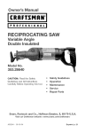
12°in. Bench
Drill Press
with
Laser°Trac
TM
Motor Specifications:
Depth Stop
Yes
Motor type
induction
Depth Stop Type
Quick Set
Continuous duty HP
1/3
Yes
Maximum developed HP 2/3
Depth Scab
Column Diameter
Amps
6,5
Base Work Area
8ol/2" wide x 9o3/8" depth
Volts
120
Depth of Throat
6"
Phase
Single
Height
34"
Hertz
60
R,P,M,
1725 (no load)
Width
11"
Depth
21"
Weight
93 pounds
2o3/8"
Product Specifications:
Belt Type
V=Belt
Pulley Type
Step
Pivoting motor mount
Number of Speeds
5
Drill Speeds
620, 1100, 1720, 2340,
3100
Spindle Taper
Jacobs 33
Chuck Taper
Jacobs 33
Chuck Type
Keyless
1/32" = 1/2"
Chuck capacity
Chuck to Table
dimension Min,
2 _
Chuck to Table
dimension Max,
t 4_
Chuck to Base
dimension
18o3/4"
Quill Diameter
1-1/2"
Quill Travel
2 o3/8"
Quill Lock
Yes
Handle Operation
360 degree rotation
Motor Control
Toggle ON/OFF with
removable Key
Table Size
8o5/8" wide x 10" depth
Table Tilt
Yes
Table Movement
Rack and pinion
Table Material
Cast Iron
Convenience:
Light
Yes
Laser
Yes
Product Capacities:
Maximum diameter
in steel
3/8"
Maximum diameter in
cast iron
1/2"
Maximum diameter
in wood
3"
To avoid electrical shock to yourself and damage to the
drill press, use proper circuit protection, Do not expose
to rain, or use in a damp environment,
The drill press is factory wired for 120V, 60 Hz, opera=
tion, Connect to a 120V, 15 amp branch circuit and use
a 15 amp time delay fuse or circuit breaker, The electri=
cal circuit cannot have any wire size less than #14, To
avoid shock or fire, replace power cord immediately if it
is damaged in any way,
GENERAL
SAFETY
iNSTRUCTiONS
Operating a drill press can be dangerous if safety and
common sense are ignored, The operator must be
familiar with the operation of the tool, Read this manual
to understand this drill press, DO NOT operate this drill
press if you do not fully understand the limitations of
this tool, DO NOT modify this drill press in any way,
REMEMBER: Your personal safety is your responsibility,
BEFORE
USUNG THE DF_ULL PRESS
To avoid serious injury and damage to the tool, read
and follow all of the Safety and Operating instructions
before operating the drill press,
1,
READ the entire instruction Manual, LEARN how to
use the tool for its intended applications,
2,
ALWAYS WEAR EYE PROTECTION, Any power
tool can throw debris into the eyes during operations, which could cause severe and permanent
eye damage, Everyday eyeglasses are NOT safety
glasses, ALWAYS wear Safety Goggles (that
comply with ANSi standard Z87,1) when operating
power tools, Safety Goggles are available at Sears
Retail Stores,
3,
4,
5,
6,
ALWAYS WEAR HEARING PROTECTION, Plain
cotton is not an acceptable protective device,
Hearing equipment should comply with ANSi
$3,19 Standards,
ALWAYS WEAR A DUST MASK TO PREVENT
INHALING DANGEROUS DUST OR AIRBORNE
PARTICLES, including wood dust, crystalline silica
dust and asbestos dust, Direct particles away from
face and body, Always operate tool in well ventilated area and provide for proper dust removal, Use
dust collection system whenever possible,
Exposure to the dust may cause serious and permanent respiratory or other injury, including silicosis
(a serious lung disease), cancer, and death, Avoid
breathing the dust, and avoid prolonged contact
with dust, Allowing dust to get into your mouth or
eyes, or lay on your skin may promote absorption of
harmful material, Always use properly fitting
NIOSH/OBHA approved respiratory protection
appropriate for the dust exposure, and wash
exposed areas with soap and water,
ALWAYS keep the work area clean, well lit, and
organized, DO NOT work in an environment with
floor surfaces that are slippery from debris, grease,
and wax,
ALWAYS unplug the tool from the electrical receptacle when making adjustments, changing parts or
performing any maintenance,
7,
8,
9,
AVOID ACCIDENTAL STARTING, Make sure that
the power switch is in the "OFF" position before
plugging in the power cord to the electrical
receptacle,
AVOID A DANGEROUS WORKING ENVIRONMENT. DO NOT Use electrical tools in a damp
environment or expose them to rain.
CHILDPROOF THE WORKSHOP AREA by removing switch keys, unplugging tools from the electrical
receptacles, and using padlocks,
10, DO NOT use electrical tools in the presence of
flammable liquids or gasses,
11, DO NOT FORCE THE TOOL to perform an operation for which it was not designed, it wiii do a safer
and higher quality job by only performing operations
for which the tool was intended,
12, DO NOT stand on a tool, Serious injury could result
if the tool tips over or you accidentally contact the
tool,
13, DO NOT store anything above or near the tool
where anyone might try to stand on the tool to
reach it,
14, DO NOT operate tool if under the influence of drugs
or alcohol,
15, EACH AND EVERY TIME, CHECK FOR DAMAGED
PARTS PRIOR TO USING THE TOOL. Carefully
check all guards to see that they operate properly,
are not damaged, and perform their intended functions, Check for alignment, binding or breaking of
moving parts, A guard or other part that is damaged
should be immediately repaired or replaced,
16, GROUND ALL TOOLS, if the tool is supplied with a
3-prong plug, it must be plugged into a 3-contact
electrical receptacle, The 3rd prong is used to
ground the tool and provide protection against
accidental electric shock, DO NOT remove the 3rd
prong, See Grounding instructions,
17, KEEP VISITORS AND CHILDREN AWAY from the
drill press, DO NOT permit people to be in the
immediate work area, especially when the electrical
tool is operating,
18, KEEP PROTECTIVE GUARDS IN PLACE AND IN
WORKING ORDER,
19, MAINTAIN YOUR BALANCE.
DO NOT extend
yourself over the tool. Wear oil resistant rubbersoled shoes. Keep floor clear of debris, grease, and
wax,
20. MAINTAIN TOOLS WITH CARE. Always keep tools
clean and in good working order. Keep all blades
and tool bits sharp.
21. NEVER LEAVE A RUNNING TOOL UNATTENDED,
Turn the power switch to the OFF position, DO
NOT leave the tool until it has come to a complete
stop,
22. REMOVE ALL MAINTENANCE
TOOLS from the
immediate area prior to turning the tool ON.
23. SECURE ALL WORK. When it is possibb, use
damps or jigs to secure the workpbce. This is safer
than attempting to hold the workpbce with your
hands.
24. STAY ALERT, watch what you are doing, and use
common sense when operating a power tool. DO
NOT USE a tool wNe tired or under the influence
of drugs, abohol, or medication. A moment of
inattention whib operating power tools may result
in serious personal injury.
25. USE ONLY RECOMMENDED
GUIDELINES
FOR EXTENSION
CORDS
The smaller the gauge number, the larger diameter of
the extension cord is. if in doubt of the proper size of an
extension cord, use a shorter and thicker cord. An
undersized cord wiii cause a drop in line voltage resulting in a loss of power and overheating. USE ONLY A
3-WIRE EXTENSION CORD THAT HAS A 3_PRONG
GROUNDING PLUG AND A 3-POLE RECEPTACLE
THAT ACCEPTS THE TOOL'S PLUG,
If you are using an extension cord outdoors, be sure
it is marked with the suffix "W°A" ("W" in Canada) to
indicate that it is acceptable for outdoor use.
Be sure your extension cord is properly sized, and
in good electrical condition. Always replace a damaged
extension cord or have it repaired by a qualified person
before using it.
Protect your extension cords from sharp objects,
excessive heat, and damp or wet areas.
ACCESSORIES.
Use of incorrect or improper accessories could
cause serious injury to the operator and cause
damage to the tool. if in doubt, check the instruction
manual that comes with that particular accessory.
26. USE A PROPER EXTENSION CORD IN GOOD
CONDITION. When using an extension cord, be
sure to use one heavy enough to carry the current
your product will draw. Please see "MiNiMUM
RECOMMENDED GAUGE FOR EXTENSION
CORDS (AWG)" table for correct sizing of an extension cord. if in doubt, use the next heavier gauge.
27. WEAR PROPER CLOTHING. DO NOT wear loose
clothing, gloves, neckties, or jewelry. These items
can get caught in the machine during operations
and pull the operator into the moving parts. Users
must wear a protective cover on their hair, if the
hair is long, to prevent it from contacting any
moving parts.
120 VOLT OPERATION ONLY
25' LONG
50' LONG
100' LONG
0 to 6 Amps
18 AWG
16 AWG
16 AWG
6 to 10 Amps
18 AWG
16 AWG
14 AWG
10 to 12 Amps
16 AWG
16 AWG
14 AWG
12 to 15 Amps
14 AWG
12 AWG
Not
recommended
THIS TOOL MUST BE GROUNDED while in use to
protect the operator from eUectric shock.
IN THE EVENT OF A MALFUNCTION
The motor supplied with your drill press is a 120 volt,
singb-phase motor. Never connect the green wire to a
live terminal.
OR BREAK-
DOWN, grounding provides the path of bast resistance
for eUectric current and reduces the risk of eUectric
shock. This tooUis equipped with an eUectric cord that
has an equipment-grounding conductor and a grounding pDg. The pUugMUST be pDgged into a matching
eUectrbaUreceptacle that is properUy installed and
grounded in accordance with ALL bcaU codes and
ordinances.
DO NOT MODIFY THE PLUG PROVIDED. if it wHUnot
fit the eUectrbaUreceptacb, have the proper eUectrbaU
receptacle installed by a qualified electrician.
IMPROPER ELECTRICAL CONNECTION of the equip°
ment-grounding conductor can result in risk of electric
shock. The conductor with the green insulation (with
or without yellow stripes) is the equipment-grounding
conductor. DO NOT connect the equipment-grounding
conductor to a live terminal if repair or replacement of
the electric cord or plug is necessary.
CHECK with a qualified electrician or service personnel
if you do not completely understand the grounding
instructions, or if you are not sure the tool is properly
grounded.
USE ONLY A 3-WIRE EXTENSION CORD THAT HAS
A 3-PRONG GROUNDING PLUG AND A 3-POLE
RECEPTACLE THAT ACCEPTS THE TOOL'S PLUG.
REPLACE A DAMAGED OR WORN CORD IMMEDIATELY.
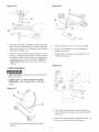
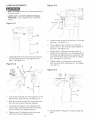
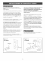
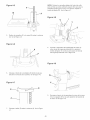
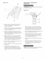
This too[ is intended for use on a circuit that has an
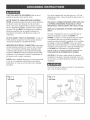
electrical receptacle as shown in FIGURE !-1.
FIGURE !-! shows a 3-wire electrical plug and electrical receptacle that has a grounding conductor. If a
properly grounded electrical receptacle is not available,
an adapter as shown in FIGURE 1-2 can be used to
temporarily connect this plug to a 2-contact ungrounded
receptacle. The adapter has a rigid lug extending from
it that MUST be connected to a permanent earth
ground, such as a properly grounded receptacle box.
THIS ADAPTER IS PROHIBITED IN CANADA.
CAUTION: In all cases, make certain the electrical
receptacle in question is properly grounded. If you are
not sure have a certified electrician check the electrical
receptacle.
This Drill Press is for indoor use only, Do not expose to
rain or use in damp locations,
Fig. 1-1
Fig. 1-2
120 Volt
120 Volt
grounding
adapter lu!
grounding
conductor
grounding
conductor
0
3-prong
electrical
receptacle
3-wire power cord
3-wire power cord
2-prong
electrical
receptacle
SPECIFIC
SAFETY
iNSTRUCTiONS
The operation of any drill press can result in debris
being thrown into your eyes, which can result in severe
eye damage, ALWAYS WEAR EYE PROTECTHON, Any
power tool can throw debris during operations, which
could cause severe and permanent eye damage.
Everyday eyeglasses are NOT safety glasses. ALWAYS
wear Safety Goggles (that comply with ANSi standard
Z87.1) when operating power tools. Safety Goggles are
available at Sears Retail Stores.
Basic precautions should always be followed when
using your drill press. To reduce the risk of injury, electrical shock or fire, comply with the safety rubs listed
below:
1.
READ and understand the instruction manual
before operating the drill press.
2,
AVOHD AWKWARD OPERATHONS AND HAND
POSHTHONS. A sudden slip could cause a serious
injury.
3.
CHECK all drill bits, cutting tools, sanding drums, or
other accessories for damage before installing in
the drill press chuck. Damaged items can cause
damage to the drill press and or serious injury.
4.
Before leaving the drill press, LOCK or REMOVE
the ON/OFF switch/key to prevent unauthorized
use,
5,
DO NOT install or use any drill bit that exceeds
7-inches in length or that extends 6-inches below
the chuck jaws. The drill bit can suddenly bend or
break.
6.
DO NOT try to drill a workpiece that is too small to
be securely held to the table or in a vise.
7.
DO NOT operate this drill press until it is assembled
and installed according to the instruction manual.
8.
DO NOT leave the drill press plugged into the electrical outlet. Unplug the drill press from the outlet
when not in use and before servicing, changing bits
and cleaning.
9.
DO NOT USE router bits, shaper cutters, circle (fly)
cutters, rotary planers or wire wheels in this drill
press.
10. FOLLOW all electrical and safety codes, including
the National Electric Code (NEC) and the
Occupational Safety and Health Regulations
(OSHA). All electrical connections and wiring should
be made by qualified personnel only.
11, LET THE CHUCK REACH FULL SPEED before
starting drill operations.
12, MAKE SURE there are no foreign objects, nails,
stones in the workpiece,
13, NEVER PERFORM LAYOUT, ASSEMBLY OR
SETUP WORK on the table/work area when the
drill press is running,
14, NEVER START THE DRILL PRESS BEFORE
CLEANING THE TABLE OF ALL OBJECTS (tools,
scrap pieces, etc,), Debris can be thrown at high
speed,
15, NEVER START THE DRILL PRESS with the drill
bit, cutting tool, or sanding drum against the workpiece, Loss of control of the workpiece can cause
serious injury,
16, OBTAIN ADVICE FROM YOUR SUPERVISOR,
instructor, or another qualified person if you are not
familiar with the operation of this drill press,
17, PROPERLY SUPPORT long or wide workpiece and
clamp to the table,
18, PROPERLY SECURE the drill bit, cutting tool, or
sanding drum in the chuck before operating the drill
press,
19, REPLACE a damaged cord immediately, DO NOT
use a damaged cord or plug, if the drill press is not
operating properly, or has been damaged, left outdoors or has been in contact with water, return it to
a Sears Service Center,
20. SECURE the drill press to the floor or work bench.
Vibration can cause the drill press to slide, walk or
tip over.
21. SECURE the workpieee firmly against the table.
Do not attempt to drill a workpiece that does not
have a fiat surface against the table, or that is not
secured by a vise. Prevent the workpiece from
rotating by damping it to the table or by securing it
against the drill press column. Loss of control of
the workpieee can cause serious injury.
22. SECURELY LOCK the head and table support to
the column, and the table to the table support
before operating the drill press.
23. The drill press is designed for home use or light
commercial duty ONLY.
24, TO REDUCE THE RISK OF ELECTRICAL
SHOCK, do not use outdoors, Do not expose to
rain, Store indoors in a dry area,
25, TURN THE DRILL PRESS OFF and unplug from
power source, Wait for the drill bit, cutting tool, or
sanding drum to come to a complete STOP before
cleaning off the table/work area, removing or securing workpiece, or changing setup,
26. USE only drill bits, cutting tools, sanding drums, or
other accessories with proper shank size recommended in this instruction manual. The wrong size
shank can cause damage to the drill press and/or
serious injury.
27, USEonlyasdescribedin thisinstruction
manual,
USEaccessories
onlyrecommended
by Sears,
28, USERECOMMENDED
SPEEDSforalloperations,
Otherspeedsmaycausethemachinetomalfunc°
tioncausingdamagetothedrillpressandor
seriousinjury,
29, information
regardingthesafeandproperoperation
ofthistoolis abo availabbfromthefollowing
ADDmONAL
SAFETY
FOR THE LASER
1,
2,
sources:
Power Tool institute
1300 Summer Avenue
Cbveland, OH 44115-2851
www, powertoolinstitute,org
3,
National Safety Council
1121 Spring Lake Drive
Itasca, IL 60143-3201
American National Standards institute
25 West 43rd Street, 4th floor
New York, NY 10036
www, ansi,org
4,
ANSi 01,1 Safety Requirements for
Woodworking Machines, and the
U,S, Department of Labor regulations
www, osha,cj__
30, SAVE THESE INSTRUCTIONS,
RULES
LASER LIGHT - DO NOT STARE INTO BEAM,
APERTURE, or into a reflection from a mirror-like
surface,
AVOID EXPOSURE - LASER LIGHT IS EMITTED
FROM BOTH SIDES OF LASER ASSEMBLY,
Use of controls or adjustments, or performance of
procedures other than those specified herein may
result in hazardous laser light exposure,
DO NOT DISASSEMBLE LASER MODULE, The
laser is a CLASS 11LASER PRODUCT that can
emit laser power up to 1 mW MAX at 635 nm,
which could result in exposure with the module
disassembled, The laser unit complies with 21
CFR 1040,10 and 1040,11,
USE OF CONTROLS OR ADJUSTMENTS OR
PERFORMANCE OF PROCEDURES OTHER
THAN THOSE SPECIFIED HEREIN MAY RESULT
IN HAZARDOUS RADIATION EXPOSURE.
Refer to them
frequently and use them to instruct other users,
AVAILABLE
ACCESSORIES
Visit your Sears Hardware Department or see the
Craftsman Power and Hand Tool Catalog for the following accessories,
iTEM
STOCK NUMBER
* Circle Cutter
25293
* Clamping Lit
* 8-in, Vise
26426
24077
* 4-in, Vise
24081
* 3-in, Vise
24071
* 21 pc, Sanding Drum Kit
25262
* 7 pc, Forstner Bit Set
25389
Sears may recommend other accessories not listed in
this manual
See your nearest Sears Hardware Department or
Craftsman Power and Hand Tool Catalog for other
accessories,
Do not use any accessory unless you have completely
read the instruction Manual for that accessory,
Use only accessories recommended for this drill press,
Using other accessories may cause serious injury and
cause damage to the drill press,
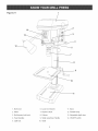
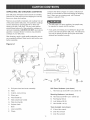
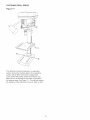
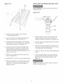
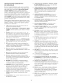
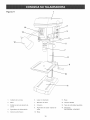
Figure
2-1
1
13
12
1, Beit cover
6, Laser (not shown)
11, Base
2, Motor
7, Keyiess chuck
12, Flexible lamp
3, Beit tension Hockknob
8, Column
13, Adjustable depth stop
4, Feed handies
9, TaMe raise/iower Handie
14, ON/OFF switch
5, QuHHHock
10, TaMe
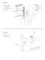
Figure
2-2
15, ON/OFF switch
16, Removable key
17, Depth scale lock nuts
18, Depth scale
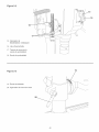
Figure
19
2-3
19, Bevel scale
20, Table lock handle
10
UNPACKING
AND CHECKING
CONTENTS
Compare the items to Figure 3-1 below; verify that all
items are accounted for before discarding the shipping
box, If there are any missing parts, call Customer
Helpline 1°800°897°7709,
This drill press will require some amount of assembly,
Remove all of the parts from the shipping box and lay
them on a clean work surface,
Remove any protective matedab and coatings from all
of the parts and the drill press, The protective coatings
can be removed by spraying WD-40 on them and
wiping it off with a soft cloth, This may need redone
several times before all of the protective coatings are
removed compbtely, CAUTION: DO NOT use acetone,
gasoline or lacquer thinner to remove any protective
coatings on your drill press,
The drill press is a heavy machine, two people may
be required to unpack and lift machine,
if any parts are missing, do not attempt to plug in the
power cord and turn ON the drill press, The drill press
can only be turned ON after all the parts have been
obtained and installed correctly,
After cbaning, apply a good quality automotive wax to
any unpainted surfaces, Make sure to buff out the wax
before assembly,
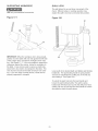
C
B
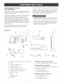
Figure
3-1
A
............
/_'_.
J
K
A,
B,
Drill press head and motor assembly
Table
C,
Column, rack and ring
D,
Worm gear
E,
F,
Feed handle (S)
Table raise/lower handle
Ddlt Press Hardware:
L,
(not shown)
Hex head cap screw M8-1,25 x 25mm (4)
Mounting
Hardware:
(not shown)
M, Hex head screw M8-1,25 x 125mm (2)
N,
Fiat Washer M8 (2)
O, Lock Washer M8 (2)
G, Table lock handle
R
Hex Nut M8-1,25 (2)
H,
I,
Keyless chuck
Base
J,
Laser assembly
Q, 2,5mm Hex wrench
K,
Clamp
R,
3mm Hex wrench
S,
4mm Hex wrench
Toots Included:
11
(not shown)
TOOLS
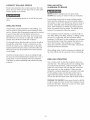
REQUIF{EB
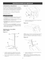
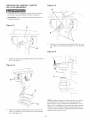
Figure
4-2
The following toob are needed for assembly and alignment, Note: Two hex wrenches (3mm and 4mm) are
provided, The remaining tools are typbal shop toob and
are not included with your drill press,
12ram Open end wrench
Hammer and block of wood
13ram Open end wrench
Combination square
#2 Phillips screwdriver
The drill press is a heavy machine; two people may
be required for certain assembly operations,
J
H
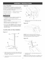
DO NOT assemble the drill press until you are sure
the tool is unplugged,
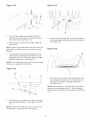
3,
DO NOT assemble the drill press until you are sure
the power switch is in the "OFF" position,
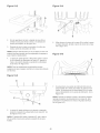
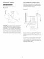
Place the worm gear (G) in the table bracket (H),
See Figure 4-2,
Figure
4-3
For your own safety, DO NOT connect the drill press
to the power source until the machine is completely
assembled and you read and understand the entire
instruction Manual,
COLUMN,
Figure
BASE and TABLE
ASSEMBLY
4-1
NOTE: Place the small end of the worm gear (I)
through hob (J), in the table bracket, See Figure 4-2,
The correct placement is shown in Figure 4-3,
Figure
4-4
B
C
Attach the column (A) to the base (B) using the four
M8x1,25x25mm hex head screws (C), two of which
are shown, See Figure 4-1,
2,
4,
insert the rack (F) in the table bracket groove (K),
See Figure 4-4,
NOTE: Place the teeth of the rack (L), see Figure 4-4 in
the teeth of the worm gear inside of the table bracket,
Loosen the set screw (D) and remove the ring (E)
and rack (F),
12
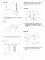
NOTE:Placethe rackunderthe bottomofthe ring,but
allowenoughclearance
so thattherackcanrotate
aroundthecolumn,Tightenthesetscrew(R), See
Figure4-7,
Figure
4-8
U
I
T
S
f
5,
SNde the rack (F) and the tabb (M) onto the column
(A), See Figure 4-5,
Figure
4-6
8,
N
I
Attach the tame raising and bwedng handb (S) on
the worm gear shaft (I) and tighten the set screw
(T) against the flat (U) on the worm gear shaft, See
Figure 4-8,
Figure
6,
Hace the bottom of the rack (N) inside the flange
(P) on the bottom of the column, See Figure 4-6,
Figure
E_
4-7
jR
9,
7,
4-9
Place the ring (E) onto the column (A), See Figure
4-7,
13
Thread the stud of the tame bck handb (V) into the
hob (W) in the rear of the tame bracket, See
Figure 4-9,
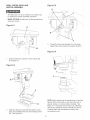
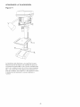
DRILL PRESS HEAD AND
MOTOR ASSEMBLY
Figure
5-3
G
\\
\
* The drHUpress is a heavy machine; two peopb may
be required for certain assemMy operations,
* MAKE CERTAIN the drHUpress is disconnected from
the power source,
Figure
5-1
A
H
F
3,
Thread the three feed handbs (F) in the three
tapped hobs (G) bcated in the pinion shaft (H),
B
Figure
1,
Seat the drHUpress head (A) on the coUumn (B),
See Figure 5-1
Figure
5-2
i
,
2,
5-4
!
C
NOTE: Make certain that the spindle taper (I) and the
tapered hob in the chuck (J) are clean and free of
grease, lacquer, or rust preventive coatings, See
Figure 5-4 Household oven cleaner can effectively
remove any substance from the spindle and chuck,
Carefully follow the manufacturer's safety rubs
concerning its use,
Align the drill press head with the table (C) and
base (D) and tighten the two head locking screws
(E), See Figure 5-2,
14
Figure
5-5
Figure
6°2
F
D
C
4,
5,
Open the chuck jaws compbteUy, hoUdthe top collar
(K) and turn the chuck barreU(L) counter-clockwise,
Make sure the jaws are compbteUy recessed inside
the chuck, See figure 5-5,
Seat the chuck onto the drHUpress spindb as far as
it wHUgo, Carefully drive the chuck onto the spindb
by pUacing a wooden bbck (M) under the chuck (N)
and tap the Mock up with a hammer (O),IMPORTANT: DO NOT tap the chuck directly with a metaU
hammer,
2,
Remove battery cover (C) from ]aser housing,
3,
Connect a 9-voUt battery (D) (not incUuded) to
battery termina] (E),
4,
PUace battery into battery compartment
repUace battery cover,
Figure
LASER
(F) and
6-3
ASSEMBLY
,, MAKE CERTAIN the drHUpress is disconnected from
the power source,
LASER LIGHT o DO NOT STARE INTO BEAM,
APERTURE, or into a reflection from a mirror-like
surface,
Figure
6-1
5,
6,
Place clamp (A) through openings (B) in laser
housing,
15
Place laser around column (G) and against the
head casting (H) and fasten the clamp securely at
the column,
Make sure laser housing is positioned so that one
laser is to each side of the head casting,
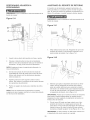
FASTENING
Figure
DRILL
PRESS
7-1
The drill press should be fastened to a supporting
surface, Secure the machine base to the supporting
surface with an M8x1,25x125mm carriage head
screw, 8,5ram fiat washer, 8,Smm lock washer, and
M8x1,25 hex nut through the two hobs (A) located in
the machine base, See Figure 7:1, This win help reduce
the tendency of the drill press to tip over, slide, or walk,
16
FLEXIBLE
* DONOTexposetheddHpressto rainoroperatethe
in dampbcations.
To reduce the risk of fire, use 40 watt or bss, 120 voUt,
reflector track-type Hght buUb(not supplied). DO NOT
use a standard househoUd Hght buUb. The reflector tracktype Hght buUbshouUd not extend bebw the Uampshade.
* MAKESUREaHpartshavebeenassembbdcorrectly
andarein workingorder.
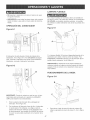
SWITCH
Figure
LAMP
OPERATION
Figure
9-1
8-1
B
The switch (A) is bcated on the front of the ddH press
head. See Figure 8-1. To turn the ddH press ON, move
the switch up. To turn the ddH press OFF, move the
switch down.
The flexible lamp (A) operates independently of the drill
press, but uses the same power cord, To turn the lamp
ON and OFF, rotate the switch (B) in the clockwise
direction only, See Figure 9-1,
Figure
CAUTION: The flexible lamp housing will remain hot for
a few minutes after turning it OFF, Avoid contact with
housing until it is cool,
8-2
B
\
TABLE
OPERATION
Figure
10-1
\\\
\\\
\
\\
\
C
IMPORTANT: When the machine is not in use, the
switch shouUd be bcked in the OFF position to prevent
unauthorized use.
1.
Grasp the switch toggle (B) and pull it out of the
switch. See Figure 8-2.
2. With the switch toggle removed, the switch will not
operate. However, should the switch toggle be
removed while the drill press is operating, the
switch can still be turned OFF, but cannot be
restarted without inserting the switch toggle.
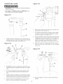
1,
17
To raise or lower the table (A) on the column (B),
loosen the table lock handle (C), See Figure 10-1,
Figure
10-2
Figure
10-4
D
G
E
2,
Turn the table raising and lowering handle (D)
clockwise to raise the table and counterclockwise
6,
to lower the table, See Figure 10-2,
3, After the table is at the desired height, tighten the
table clamp,
NOTE: Always raise (rather than lower) the table to the
final position to allow the gears to mesh and prevent
slippage,
4,
Loosen the table locking bolt (G) and tilt the table to
the desired angle, and tighten the table locking bolt,
See Figure 10-4,
Figure
10-5
H
The table (A) can be rotated 360 degrees on the
column (B) by loosening the table clamp (C) and
rotating the table to the desired position, and tightening the table clamp, See Figure 10-1,
NOTE: For thru-drilling operations, make sure the table
center hob is aligned with the drill bit,
100
Figure
0
100
200
10-3
7,
A tilt scab (H) is provided on the table bracket casting to indicate the degree of tilt, A witness line (I) is
provided on the table to align with the tilt scab,
See Figure 10-5,
NOTE: When the table is returned to the level position,
replace the table alignment pin (E), This will position
the table surface 90 degrees to the spindle, See Figure
10-3,
5,
The table (A) can be tilted right or left by removing
the table alignment pin (E), See Figure 10-3 and
10-4,
NOTE: if the pin (E) is difficult to remove, turn the nut
(F) clockwise to pull the pin out of the casting,
18
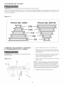
DRULL SPEEDS
MAKE CERTAIN the drill press is disconnected from the power source,
Five drill speeds (620, 1100, 1720, 2340, and 3100 RPM) are available with your drill press, See Figure 11-1 to select
the correct spindle speed for your operation, This diagram can also be found on the inside of the belt cover of the
drill press,
Figure
11-1
SPINDLE PULLEY
CHANGUNG
ADJUSTING
MOTOR
SPEEDS AND
BELT TENSUON
MAKE CERTAIN the ddH press is disconnected from
the power source,
Figure
1,
Open the beUtcover (A), See Figure 12-1,
2,
Loosen the tension Uockknob (B) to reUease beUt
tension, Pivot the motor (C) toward the front of the
ddH press,
3,
Hold the motor in this position and pUace the beUt
(D) on seUected pulleys according to the ddH speed
diagram,
4,
Move the motor to the rear until the beUthas proper
tension,
12-1
D
PULLEY
NOTE: The beUtshouUd be just tight enough to prevent
slipping, Excessive tension wHUreduce the Hfe of the
beUt,pulleys and bearings, Correct tension is obtained
when the belt (D) can be flexed about 1" out of line midway between the pulleys using light finger pressure,
5,
\\
B
19
Tighten the tension lock knob (B),
DRULLING
HOLES
TO DEPTH
ADJUSTING
SPRUNG
The ddH chuck wHUautomatically return sUowUyto its
upper position when the handUe is reUeased, The return
spring was propedy adjusted at the factory, However, to
adjust, if necessary:
MAKE CERTAIN the drill press is disconnected from
the power source.
Figure
RETURN
13-1
MAKE CERTAIN the ddH press is disconnected from
the power source.
Figure
14-1
D
C
C
0
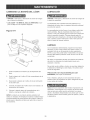
1.
1.
Unsert the ddH bit into the keyUess chuck and tighten.
2.
Hace the workpiece on the ddH press tame. Raise
the drHUpress tame until the workpiece is 1/8-in
from the drill bit.
Loosen both nuts (A) and (B). Make sure that the
spring housing (C) remains engaged with head
casting (D). See Figure 14-1.
Figure
14-2
C
E
NOTE: Make sure the workpiece is secured to the table
properly.
3.
Turn the two lock nuts (A) on the thread depth scale
(B) until the bottom lock nut is aligned with the
dimension you want to drill on the scale (C).
4.
Tighten the top lock nut against the bottom nut.
This will keep the lock nuts from moving during
drilling operations.
5.
2,
Drill a test hole to check the depth.
NOTE: For thruodrilling operations, make sure the table
center hole is aligned with the drill bit.
While firmly holding the spring housing (C) pull the
spring housing out and rotate it (counteroclockwise
to increase or clockwise to decrease the spring ten°
sion) until the boss (E) is engaged with the next
notch (F) on the spring housing, See Figure 14-2,
IMPORTANT: Because the return spring is under tension,
it will want to unwind (clockwise), Make sure you have
a firm hold of the spring housing before pulling it out,
3,
Turn the nut (B) until it contacts the spring housing
(C), then back the nut (B) out 1/4 turn from the
spring housing (C), Tighten the nut (A) against the
nut (B) to lock the nuts from turning, See Figure
14-1 and 14-2.
IMPORTANT: The inside nut should not contact spring
housing when tightened.
2O
LASER
ADJUSTMENTS
Figure
15-3
MAKE CERTAIN the drill press is disconnected from
the power source,
J
• LASER LIGHT - DO NOT STARE INTO BEAM,
APERTURE, or into a reflection from a mirror-like
surface,
Figure
15-1
/
'
i
i
1,
_--C
Install alignment pin (A) into chuck (B), make sure
that the pointed end (C) of the alignment pin is
down, See Figure 15-1,
F
6,
Loosen the two screws (U)on the face (J) of the left
side laser, See Figure 15-3,
7,
On the alignment pin (A) there is a vertical line
scribe (L) into it, This is used to set parallelism of
the lasers, See Figure 15-4,
8,
Using knob (K), rotate the laser beam until it is
exactly on the vertical line (L) on the alignment pin,
The chuck and alignment pin may need to be rotated to allow the laser beam to fall onto the vertical
line, See Figure 15-3 and 15-4,
9,
Tighten screws (I), making sure the laser beam
does not move off the vertical line (L), See Figure
15-3 and 15-4,
E
Figure
15-4
H
2,
Turn the laser ON with the rocker switch (D) on the
left side of the laser housing, See Figure 15-2,
3,
With the 2,5mm hex wrench (E), loosen the screw
(F) in the top, left side of the laser housing,
4,
Using knob (G) located on the underside of the
laser housing, rotate the laser beam (H) until it is
close to center on the alignment pin (A),
5,
Tighten screw (F), making sure the laser beam
does not move off the alignment pin,
10, Repeat STEPS 2 through 9 to setup the right side
laser,
21
Figure
15-5
iNSTALLiNG
AND REMOVING
DRILL
BiTS
MAKE CERTAIN the drill press is disconnected from
the power source,
Figure
16-1
ii'' ....
i
O
N
jB
11, Adjust the drHUpress tame so that it is about
1" under the alignment pin,
1,
12, Lay a 3/4" piece of wood (M) onto the drill press
table under the line pin, See Figure 15-5,
13, Using the drill press feed handle, lower the alignment pin down and mark (N) the wood, Make sure
the wood does not move, See Figure 15-5,
2,
3,
14, Loosen the screw (F) in the top, left side of the
laser housing and using knob (G) located on the
underside of the laser housing, rotate the laser
beam (0) until crosses mark (N) in the wood, See
Figure 15-2 and 15-5,
Hold the collar (A) and turn the chuck barrel (B)
counter-clockwise to close the chuck jaws and
clockwise to open the chuck jaws, See figure 16-1,
Open the chuck jaws slightly larger than the diameter of the drill bit
insert the smooth end of drill bit in the chuck as far
as it wiii go, and then back the bit out 1/16" (or up
to the beginning of the drill bit flutes),
15, Tighten screw, making sure the laser beam does
not move off the mark,
16, Repeat STEPS 14 and 15 to set the right side laser,
17, Move the wood about 1" and mark it again, checking that the mark is position where the two laser
beams cross, if it does not repeat STEPS 13
through 16 above,
4,
Center the drill bit in the chuck before tightening the
chuck,
5,
To securely tighten the bit in the chuck, hold the
collar (A) with one hand and with the other hand
tighten the barrel (B) counter-clockwise,
See
Figure 16-1,
NEVER run drill press to install or tighten a drill bit or
cutter in the keyless chuck,
22
SUPPORTING
WORKPIECE
USE only recommended
Figure
QUILL
LOCK
The quill allows the up and down movement of the
chuck, Different setup or working operation may
require the quill to be lower and locked into position,
accessories,
17-1
Figure
18-1
C
o
o
A
B
IMPORTANT: When the workpiece (A) is long enough,
position it on the table with one end against the left side
of the column (B) to prevent the workpiece from rotating, See Figure 17ol, if it is not possible to support the
workpiece against the column, clamp the workpiece to
the table, A vise can be used to secure a small workpiece that is too small to be clamped to the table, The
vise must be secured to the table to keep it from rotating, if you are using a backup board, it must also be
properly supported or clamped,
Lower quill (A) to desired depth and tighten quill locking
handle (B), The quill locking handle is spring loaded
and can be repositioned by pulling out on the hub (C)
and rotating it, See Figure 18-1,
To unlock the quill, hold onto the feed handle and
loosen the quill locking handle, The quill is spring
loaded and wiii return back up into the drill press head
casting, Be sure to hold onto the feed handle to control
the speed in which the quill returns,
23
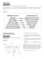
CORRECT
DRiLLiNG
SPEEDS
DRULUNG METAL,
ALUMINUM
OR BRASS
Factors that determine the correct speed are: the workpiece, the size of the hoUe,the type of bit or other cutter,
and the quality of cut wanted,
NEVER hold the workpiece in your bare hands.
ALWAYS use clamps or vises to hold your workpiece.
Use the recommended
piece.
DRiLLiNG
speed for the ddH bit and work-
Twist drill bits should only be used in drilling metals.
Never hold the workpiece in your bare hands; always
use clamps or vises. The drill bit may seize the work at
any time, especially when breaking through the workpiece. If the workpiece is whirled out of the operator's
hand, the operator may be injured. The drill bit will be
broken if the workpiece strikes the column.
WOOD
Twist drill bits, usually intended for metaUdrHHng, can
aUso be used for boring hoUes in wood. However, brad
point or Forstner bits are generally preferred for working
in wood. These bits cut a fiat bottom hoUeand are
The workpiece must be clamped or securely held in a
vise while drilling. Any tilting, twisting, or shifting results
not only in a rough hole, but also increases drill bit
breakage. For flat work, lay the workpiece on a wooden
base and clamp it firmly down against the table to prevent it from turning. If the workpiece is of irregular
shape and cannot be laid flat on the table, it should be
securely blocked and clamped.
designed for removaU of wood chips. Do not use hand
bits which have a screw tip or auger bits. At drill press
speeds, they will Hft and rotate the workpiece.
For through boring, align the table so that the bit will go
through the center hole. Scribe a vertical line on the
front of the column and a matching mark on the table
bracket and the drill press head, so that the table and
drill press head can be clamped in the center position
at any height.
When drilling metal, it will be necessary to lubricate the
tip of the drill bit with oil to prevent it from overheating.
Feed the bit slowly when it is close to cutting through
the wood to prevent splintering the bottom face. Use a
scrap piece of wood as backup under the workpiece.
This helps to reduce splintering and protects the point
of the bit.
DRILUNG
OPERATION
Use a center punch to dent the workpiece where you
want the hole. This will keep the bit from walking when
you start the drill operation. Before turning the drill
press ON, turn the laser ON and align the cross-hairs
with center mark on the workpiece. Make sure the
workpiece is properly supported or secured to the table.
For thru-drilling, make sure the table center hole is
aligned with the drill bit. Turn the drill press ON and
start to feed the drill chuck down with the feed handles.
FEEDING TOO RAPIDLY may cause the belt or drill bit
to slip or break, the motor to stall, the workpiece to pull
loose from the table, Never try to rush your work; allow
the drill press to work smoothly,
24
CHANGmNG LASER
BATTERY
Turn the power switch OFF and unplug the power
cord from its power source,
Turn the power switch OFF and unplug the power cord
from its power source,
LASER UGHT - DO NOT STARE mNTOBEAM,
APERTURE, or into a reflection from a mirror-like
surface,
Figure
The drill press has sealed lubricated bearings in the
motor housing that do not require any additional lubrication from the operator,
19-1
The quill and spindle assemblies should be periodically
lubricated, Lower the quill assembly and squirt or wipe
a thin film of lightweight machine oil on the entire surface, Place a few drops of light machine oil down the
spindle assembly, Raise and lower the quill several
times to distribute the oil evenly,
F
With the drill press unplugged, blow off motor with low°
pressure air to remove dust or dirt, Air pressure above
50 P, S, I, should not be used as high-pressured air
may damage insulation, The operator should always
wear eye protection when using compressed air,
Do not use a shop vacuum to clean metal shavings.
The metal shavings can cause an explosion or fire.
Do not allow chips and dust to accumulate under drill
press, Keep area clean and in safe order,
1.
Remove battery cover (A) from laser housing.
2.
Remove the 9-volt battery from the battery compartment (B).
3.
Disconnect the 9-volt battery (C) from battery
terminal (D).
4.
Connect a new 9-volt battery (not included) to
battery terminal.
5.
Place battery back into battery compartment
replace battery cover.
CAUTION: DO NOT USE FLAMMABLE
to clean the drill press.
MATERIALS
After cleaning, apply a good quality automotive wax to
any unpainted surfaces, Make sure to buff out the wax
before assembly,
ONLY trained personnel should perform repairs to the
drill press, Contact your nearest Sears Service Center
for authorized service, Unauthorized repairs or replace°
ment with non-factory parts could cause serious injury
to the operator and damage to the drill press,
and
NOTE: The battery is a 9-volt standard alkaline battery
(not included). When replacing the battery, the battery
terminals should be thoroughly cleaned. Use a soft
paintbrush or similar device, to remove all sawdust and
debris.
25
TOPREVENT
INJURYTOYOURSELF
or damageto theddHpress,turntheswitchtotheOFFpositionandunpUug
thepowercordfromtheeUectrbaU
receptacle
beforemakinganyadjustments,
PROBLEM
Motor does
not start or
does not come
up to full
speed
UKELY CAUSE(S)
SOLUTION
1. Switch key is removed.
1. insert switch key.
2. Defective switch.
2. Have switch replaced.
3. Defective capacitor.
8. Have capacitor replaced.
4. Low line voltage.
4. Correct !ow line voltage condition, if machine is
plugged into an extension cord, disconnect and plug
directly into wall outlet.
5. Defective motor.
5. Have motor replaced.
NOTE: #3 and #4 must be done by a qualified service
technician; Consult Sears service.
Motor stalls or
circuit breakers
open frequently
1. Circuit overload.
1.
2. Correct low line voltage condition. Check line voltage
with a multi-meter, if the machine is plugged into an
extension cord, unplug it from the extension cord and
plug directly to the wail outlet.
2. Low line voltage.
3. Motor overload.
3.
4. incorrect fuses on circuit breakers.
Drill bit stalls
or slips
DrH_ bit or
matedam
smokes
or
burns
E×cessive drill bit
runout or wobbme
Reduce load on motor, slow down feed rate.
4. Have correct fuses on circuit breakers installed by a
qualified electrician.
5. Short circuit in motor; loose connections
or worn insulation on lead wires.
Motor running
too hot
Reduce circuit load (turn off other appliances).
inspect terminals in motor for damaged insulation and
shorted wires and have them replaced. Check all
power lead connections.
1. Restricted air circulation due to dust
accumulation.
1. Clean dust and restore normal air circulation around
motor.
2. Motor overload.
2. Reduce load on motor, slow down feed rate.
1. Belt is incorrectly tensioned.
1.
2. Drill bit is not securely tightened in
chuck.
2. install drill bit properly. See installing and removing drill
bit in "OPERATIONS AND ADJUSTMENTS".
1. incorrect spindle speed.
1.
2. Chips not exiting out of drill hole.
2. Retract drill bit frequently during drilling operation to
clear chips from hob.
3. Dull drill bit.
3. Replace or sharpen drill bit.
Adjust belt tension. See changing speeds and adiusting
belt tension in "OPERATIONS AND ADJUSTMENTS".
Reduce spindle speed. See speed diagram on the
underside of the belt cover.
1. Bent drill bit.
1. Replace with a straight or new drill bit.
2. Drill bit not properly installed in chuck.
2. install drill bit properly. See installing and removing drill
bit in "OPERATIONS AND ADJUSTMENTS".
Spindle returns too
slow or too fast
1. Return spring has incorrect tension.
1. Adjust spring tension. See adjusting spindle return
spring in "OPERATIONS AND ADJUSTMENTS".
Chuck will not
stay onto spindme
1. Grease, dirt or oil on spindle taper or
in chuck taper.
1. Clean grease, dirt or oil off of spindle taper and chuck
taper. See drill press head and motor assembly in
"ASSEMBLY iNSTRUCTiONS".
26
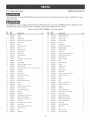
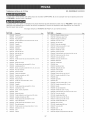
12qn.BenchDrill Press
MODELN0.152.219110
Whenservicing,useonUy
CRAFTSMAN
repUacement
parts,Useof anyotherpartsmaycreatea HAZARD
or cause
productdamage,
Anyattemptto repairor repUace
eUectricaU
partsonthisdrHU
pressmaycreatea HAZARDunUess
a qualifiedservice
technician
doesrepairs,Repairserviceis avaHaMe
atyournearestSearsServiceCenter,
AUways
orderby PARTNUMBER,
notbykeynumber,
KEY
NO,
PART
NO,
DESCRiPTiON
KEY
NO,
PART
NO,
1
0R92656
V-Belt
DESCRiPTiON
1
44
0R92730
Serial Number Label
2
0R92657
1
Hex Nut
1
45
0R92728
5ram Drive Screw
3
4
OR92658
Spindle Pulley
1
46
OR92670
Warning
1
4
OR90222
M6xl0mm
1
47
OR90228
10ram Hex Nut
2
5
OR92662
Motor Pulley
1
48
OR92675
Stop Rod
1
6
OR92659
Sleeve
1
49
OR92674
Depth Scale
1
7
OR90218
Ball Bearing
2
50
OR92720
M5x12mm
2
8
OR92660
Spacer
1
51
OR92676
Mounting
9
OR90218
Ball Bearing
2
52
OR92677
Rubber Washer
1
10
OR92732
Ext Ret Ring
1
53
OR92678
Stop Collar
1
11
OR92733
Ext Ret Ring
1
54
OR90222
M6xl0mm
Hex Soc Set Screw
1
12
OR92734
Ball Bearing
1
55
OR92723
M6x40mm
Hex Hd Screw
1
13
OR92661
Knob
1
56
OR90235
M6mm Hex Nut
1
14
OR90716
M4,2x12mm
1
57
OR90927
M10mm
1
15
OR92664
Grommet
1
58
OR92679
Quill
16
OR92663
Cord Insulator
2
59
OR92734
Ball Bearing
17
OR90241
M6x12mm
4
60
OR92680
Spindle
1
18
OR90059
M6.4 Flat Washer
4
61
OR92681
Keyless Chuck
1
OR92651
Pulley Cover Assy const of, (19,20,21,22,2&24,)
1
62
OR92682
Lock Handle
1
19
OR92654
Nameplate
1
63
OR92683
Special Screw
1
20
OR92652
Top Guard
1
64
OR90307
M8 Hex Nut
1
21
OR92653
Speed Chart
1
65
OR92684
Shaft Pinion Assy incl, (66,67)
1
22
OR90431
M4.3 Ext Tooth Washer
4
66
OR92721
M5x20mm
1
23
OR90078
M4 Hex Nut
4
67
OR92685
Hub
1
24
OR92655
Bottom Guard
1
68
OR92686
Handle
3
26
OR90761
M5xl0mm
3
69
OR92687
Ball
27
OR92665
Clamp
3
70
OR92688
M8x17mrn
Thumb Screw
1
28
OR92666
Sleeve
3
71
OR92722
M6x16mm
Spring Pin
2
29
OR91774
M4xl0mm
4
72
OR92691
Spring
1
30
OR92727
1/2-20 Jam Nut
2
73
OR92690
Slide Rod
1
31
OR92667
Spring and Housing Assy
1
74
OR92689
1/4" Rubber Washer
4
32
OR92668
Retainer
1
75
OR90283
M8x8mm
2
33
OR92669
Spring Seat
1
76
OR92724
M8 Lock Nut
2
34
OR90283
M8x8mm
1
77
OR91499
M8.4mm
2
35
OR90362
M5,3 Ext Tooth Washer
4
78
OR92735
M8x25mm
Hex Hd Screw
2
36
OR90507
M5x8mm
2
79
OR90310
M8x16mm
Hex Hd Screw
4
37
OR92671
Switch Box
1
80
OR91499
M8.4mm
38
OR90505
M5x12mm
2
81
OR92692
Motor Plate
1
39
OR92672
Switch Plate
1
82
OR91499
M8.4mm
8
40
OR90716
M4,2x12mm
2
83
OR90307
M8 Hex Nut
4
41
OR90037
Switch incl, (42)
1
84
OR92693
Key
1
42
OR90038
Key
1
85
OR92694
Motor incl, (86)
1
43
OR92673
Headstock
1
86
OR92729
Motor Spec Label
1
QTY,
Hex Soc Set Screw
6203
6203
6201
Pan Hd Tap Screw
Cheese
Hd Screw
Pan Hd Screw
Cheese
Hd Screw
Hex Soc Set Screw
Cheese
Cheese
Hd Screw
Hd Screw
Pan Hd Tap Screw
27
QTY.
Label
Flat Hd Screw
Bracket
Lock Nut
1
1
6201
Roll Pin
1
3
Hex Soc Set Screw
Flat Washer
Flat Washer
Flat Washer
8
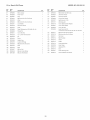
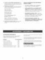
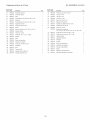
12-in.BenchDrill Press
KEY
NO.
PART
NO.
87
MODELN0.152.219110
DESCRiPTiON
QTY=
KEY
NO.
PART
NO,
DESCRiPTiON
0R92695
Motor Jumper
1
110
0R92725
M8x125mm
88
0R92696
Power Cord
1
111
0R90290
3ram Hex Wrench
1
89
0R92697
Ring
1
112
0R90291
4ram Hex Wrench
1
90
0R90222
M6xlOmm
1
113
0R90289
2.5ram Hex Wrench
1
91
0R92702
Worm
1
114
0R92707
Light Assy incl, (115)
1
92
0R90222
M6xlOmm
1
115
0R91317
Warning
1
93
0R92701
Lock Handle
1
116
0R92719
lOmm
External Tooth Washer
1
94
0R92728
5ram Drive Screw
2
117
0R90227
lOmm
Lock Washer
1
95
0R92700
Scale
1
118
0R90228
lOmm
Rex Nut
1
96
0R92698
Table W/Bracket
1
0R92428
97
0R92699
Thread Pin
1
Laser Assy const of,
(119,120,121,122,123,124,125,126,127,128,129)
98
0R90071
1/4-20 Hex Nut
1
119
0R92717
M4x14mm
Hex Soc Hd Screw
2
99
0R92726
1/2-12 x7/8" Rex Hd Screw
1
120
0R92718
M3x14mm
Hex Soc Hd Screw
6
100
0R92708
Pin
1
121
0R92711
Top Cover
1
101
0R92703
Pinion
1
122
0R92712
Main Housing
1
102
0R92369
Handle Assy
1
123
0R92713
Switch
1
103
0R92705
Column W/Flange
1
124
0R92715
Holder
104
0R90308
M8x2Omm
4
125
0R92716
Lasermodule
105
0R92704
Rack
1
126
0R92709
Hose Clamp
1
106
0R92706
Base
1
127
0R92710
Alignment
1
107
0R90307
M8 Hex Nut
2
128
0R92714
Door
108
0R90248
M8.4mm
Lock W!asher
2
129
0R92731
Laser Warning
109
0R91499
M8.4mm
Flat Washer
4
130
0R93515
Owner's
Hex Soc Set Screw
Hex Soc Set Screw
incl (97,98,99,100,101
Hex Rd Screw
)
28
QTY=
Hex Hd Screw
Label
2
2
Assy
Pin
2
1
Manual
Label
(not shown)
2
1
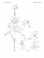
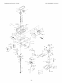
12-in.BenchDrill Press
MODELN0.152.219110
/o/!8
(2)
.,4
/"
U
26
27
2B (3
(4)
(4)
33
35
36
38
(2)_
(2)
4[\
40
96
(2)/
)
120
(6)
(2)
f6o
6]
29
30
®
1/3 CabaHos de Fuerza (servicio continuo)
2/3 CabaHos de Fuerza (m_ximo desarroHado)
5 Velocidades,
Polea Escamonada
Gama de Velocidades de PerforaciSn
620o3100 R.P.M.
12P
No. de Mode_o
152.219110
PARA SU SEGURJDAD PERSONAL,
Reay
obedezca todas Uas lnstrucciones
de
Seguddad y Operaci6n antes de operar
esta Taladradora de Banco
Linea de Ayudaal Qiente
1-800-897-7709
Sirvase tenor listo su
No. de Modelo y No. de Sede
Sears,
Roebuck
and Co., Hoffman
Estates,
No. de Pieza OR93515
31
JL 60179 U.S.A.
SECO[ON
PAG[NA
Garant_a .........................................................................................................................................................................
32
Especificaciones
de[ producto ....................................................................................................................................
33
de seguridad .........................................................................................................................................
34
[nstrucciones
Directrices
para [as e×tensiones
[nstrucciones
de cone×i6n
[nstrucciones
de seguridad
Accesorios
Conozca
y aditamentos
a tierra .............................................................................................................................
especfficas
....................................................................................................................
35
36
37
...........................................................................................................................................
38
..................................................................................................................................................
39
de [a caja ....................................................................................................................................................
41
su m&quina
Contenido
e[_ctricas ...............................................................................................................
[nstrucciones
de montaje ............................................................................................................................................
42
Operaciones
y aiuste ...................................................................................................................................................
47
Mantenimiento
..............................................................................................................................................................
Guia de [oca[izaci6n
de averias ..................................................................................................................................
Listado de piezas ..........................................................................................................................................................
[nformaci6n
de $ervicio ..........................................................................................................................
GARANTiA COMPLETA DE UN ANO PARA LAS HERRAMIENTAS
Contraportada
CRAFTSMAN
Siesta herramienta Craftsman Ibgase a failar debido a defectos materiabs o de elaboraci6n dentro de un aho a partir de la
fecha de compra, LLAME AL 1-800-4-MY*HQME @ (en EE,UU,) PARA CQQRDINAR LA REPARACION GRATUITA,
Si se utiliza esta herramienta con fines comereiaies o de alquiler, esta garant[a se aplicara por s6io noventa d[as a partir de la
fecha de compra,
Esta 9arantfa se apliea s61o mientras que esta herramienta
Esta garantfa le concede derechos bgabs
se encuentre en los Estados Unidos,
espeeifieos, y tambien podrb_ tenet otros derechos que var[an de un estado al otto,
Sears Roebuck and Co, Dept 817 WA, Hoffman Estates, iL 60179
32
55
56
57
Taladradora
de Banco
con LaseroTrac TM
_ecificaciones
de 12 pu_g°
deI Motor:
Tipo de Motor
Inclinaci6n de Mesa
S[
Movimiento
Cremallera y pi_6n
de Mesa
Material de Mesa
Hierro moldeado
Tope de Profundidad
S[
Tipo de Tope de Profundidad
Quick-Set
Inducci6n
HP Servicio Continuo
1/3
HP Maximo Desarrollado
2/3
Ampefios
6.5
Escala de Profundidad
S[
Voltios
120
Diametro de Columna
2-3/8 pulg=
Fase
Monofasico
Zona de Trabajo Basica
Hertzios
60
8-1/2 pulg. de ancho x
9-3/8 pulg. de profundidad
R.RM.
1725 (sin carga)
Profundidad de Garganta
6 pulg.
Alto
34 pulg.
Profundidad
11 pulg.
Peso
93 libras
_ecificaciones
deI Producto:
Tlpo de Correa
Corre8
Tlpo de Polea
EscaIonada
en
"V"
Montaje de motor pivotante
Conveniencia:
NOmero de Velocidades
5
Luz
Si
Velocidades de Perforaci6n
620, 1100, 1720, 2340,
3100
Laser
Si
Ahusado del HusoJacobs
33
Ahusado del Mandrino
Jacobs 33
Tipo de Mandrino
Sin Ilave
Capacidad del Mandrino
1/32-1/2 pulg.
Dimensi6n M[n. de Mandrino
a Mesa
2 putg,
Dimensi6n Max.de Mandrino
a Mesa
14 pulg.
Dimensi6n de Mandrino a Base
18-3/4 pulg.
Diametro deI _,rbol Hueco
1-1/2 pulg.
Recorrido del Arbol Hueco
2-3/8 putg.
Cierre dei _,rbol Hueco
S[
Operaci6n de Agarradera
Rotaci6n a 360 grados
Control del Motor
Interruptor de palanca
ENCENDIDO / APAGADO
con Ilave desmontable
Dimensiones de Mesa
8-5/8 pulg. de ancho x
10 pulg. de profundidad
Tensionamiento
de Correa
_acJdades
det Producto:
Diametro maximo en acero
3/8 pulg.
DJ_metro maximo en hierro
moJdeado
1/2 pulg.
Diametro maximo en madera
3 pulg.
Use la proteccJ6n adecuada de circuJtos para evitar los
choques etectricos y el daBo a la taladradora. No Ia exponga
a la Iluvia ni haga uso de ella en entornos hOmedos.
La taladradora viene cableada de fabrica para el funcionamiento a 120 V, 60 Hz. Conectela a un circuito de derivaci6n
de 120 V, 15 amperios y utilice un fusible de retardaci6n de
tiempo o un disyuntor de circuitos de 15 amperios. El circuito
electrico no podra tener un tama[io de alambre inferior al #14.
Para evitar choques electricos o incendios, reponga el cord6n
de energia tan pronto como quede dahado de cuatquier
manera.
33
INSTRUCCIONES
DE SEGURIDAD
GENERALES
El uso de una taIadradora puede ser peligroso si se hace
caso cruise de la seguridad y el sentido comon. El operario
debe estar famifiarizado con et funcionamiento de esta herramienta. Lea este manual para entender esta taladradora. NO
OPERE esta taladradora si no entiende plenamente las Iimitaciones de esta herramienta. NO MODIFIQUE este taIadradora
de ninguna manera. REOUERDE: Su seguridad personal es
su responsabiiidad.
2.
UTILICE PROTECCION OCULAR SlEMPRE. Cualquier
herramienta mecanica puede expuIsar escombros hacia
los ojos durante Ias operaciones, causando daRo ocular
grave y permanente. Los anteojos de use cotidiano NO
son gafas de seguridad. Utiiice gafas de seguridad (que
cumplan con la normativa Z87.1 de ANSb StEMPRE
cuando vaya a operar herramientas mec_inicas. Las
gafas de seguridad estg,n disponibles en las tiendas de
Ventas al Detal de Sears.
3.
UTILICE PROTECCION AUDmVA SlE_,_PRE. El algod6n por sf solo no constituye un dispositivo de protecci6n
aceptable. El equipo auditNo debe eumplir con las
normativas S3.19 de ANSI.
4.
UTJUCE SlEMPRE UNA CARETA CONTRA EL POLVO
PARA EVITAR ASPIRAR POLVOS PEUGROSOS O
PART_CULAS EN EL AtRE, incluyende polvo de madera,
pelvo de sflice cdstalino y polvo de asbesto. Didja las
partfcuias en direcci6n opuesta a! rostro y ei cuerpo.
Opere la herramienta siempre en una zona bien ventilada
y proporcione Ia remoci6n apropiada de! polvo. UtiIice un
sistema de recolecci6n de polvo siempre que sea posF
ble. La exposici6n al polvo puede ocasionar dares respiratodos graves y permanentes u otras heridas, inciuyendo silicosis (una enfermedad pulmonar grave), cancer y
la muerte. Evite aspirar el polvo y evite e! contacto proIongado con el polvo. El permitir Ia entrada deI polvo en
su boca u oios, o deiar que permanezca sobre su pieI,
puede promover la absorci6n de material daRino. Utilice
protecci6n respiratoria aprobada per NIOSH/OSHA, de
ajuste correcto y apropiada para la exposici6n ai polvo, y
lave Ias zonas expuestas con iab6n y agua.
5.
6.
8.
EVITE UN ENTORNO DE TRABAJO PEUGROSO. NO
utilice Ias herramientas electricas en entornos h0medos
ni las exponga a la Iluvia.
9.
HAGA SU TALLER A PRUEBA DE NINOS al quitar las
Ilaves de los interruptores, desenchufando Ias herramientas de sus tomacorrientes y usando candados.
11. NO FUERCE LA HERRAMiENTA a realizar una
operaci6n para la que no fue diseRada. Realizarb, un
trabajo m_s seguro y de mayor calidad s61o efectuando
aqueilas operaciones para las que fue diseRada.
Lea y obedezca todas las instrucciones de Seguridad y
Operaci6n antes de operar la taladradora para evitar hendas
graves y daRo a la herramienta.
LEA el Manual de Instrucciones cabalmente. APRENDA
como usar la herramienta para su aplicaci6n propuesta.
EVITE LOS ARRANQUES ACCIDENTALES. Aseg0rese
de que el interrupter de energ[a se encuentre en la posici6n de "OFF" (apagado) antes de enchufar el cord6n de
potencia y causar dare a la herramienta.
10. NO utilice herramientas electricas en la presencia de
I[quidos o gases inflamables.
ANTES DE HACER USO
DE LA TALADRADORA
1.
7.
12. NO se pare sobre la herramienta. Esto podrfa resultar en
heridas graves si la herramienta se vuelca o si usted
hace contacto accidental con la herramienta.
13. NO almacene nada sobre o cerca de Ia herramienta
deride alguien pueda intentar pararse sobre la herramienta para alcanzarto.
14. NO opere la herramienta si se encuentra bajo la infiuencia del alcohol o de las drogas.
15. EN TODA Y CADA OCAS_0N, REVISE SJ EXtSTEN
PIEZAS DANADAS ANTES DE OPERAR LA HERRAMIENTA. Revise todos los protectores cuidadosamente
para asegurarse de que funcionen correctamente, que no
esten daRados, y que realicen sus funciones destinadas.
Revise la alineaci6n y busque Ia atascadura o ruptura de
todas las piezas en movimiento. Un protector, una pieza
de inserci6n u otra pieza daRada debe repararse y sustituirse inmediatamente.
16. CONECTE TODAS LAS HERRAMIENTAS A TIERRA.
Si Ia herramienta viene equipada con un enchufe de tres
roaches, se Ie debe enchufar en un tomacorrientes de
tres contactos. El tercer macho se utiliza para conectar la
herramienta a tierra y ofrecer protecci6n contra !os
cheques electricos accidentales. NO quite ei tercer
macho. Ver Instrucciones de Conexi6n a Tierra.
17. MANTENGA
ALEJADOS
A LOS VISITANTES
Y NtNOS
de la taladradora. NO permita que haya gente en la zona
inmediata de trabajo, sobre todo cuando Ia herramienta
electrica se encuentre en funcionamiento.
18. MANTENGA TODOS LOS PROTECTORES EN SUS
SITIOS Y EN BUENAS CONDICIONES DE TRABAJO.
19. MANTENGA SU EQUILIBRIO, NO se extienda sobre la
herramienta. Utilice calzado con suetas de caucho y
resistentes al aceite. Mantenga el piso despejado de
escombros, grasas o cera.
Mantenga Ia zona de trabaio limpia, bien iIuminada y
organizada EN TODO MOMENTO. NO trabaje en un
entomo con superficies de piso resbalosas debido a los
escombros, grasas y cera.
20. MANTENGA SUS HERRAMIENTAS CON CUIDADO.
Mantenga sus herramientas limpias yen buen estado de
funcionamiento siempre. Mantenga filosas todas las
hoias y las brocas.
Desenchufe la herramienta del tomacorrientes SIEMPRE
que vaya a reaiizar cuaIquier ajuste, recambio de piezas
o Ilevar a cabo cuatquier tarea de mantenimiento.
34
21. NUNCA
DEJEUNAM_,QU_NA
ENFUNCJONAM_ENTODIRECTRJCES PARA LAS
SiNATENDER
Apague
elinterrupter
deenerg[a
a Ia
EXTENSUONES ELECTRICAS
posici6n
de"OFF"
(apagado).
NOsealejedeJamb,
quina
Mientras menor sea el n0mero de calibre, mayor sera el
hastaquesehayadetenido
percompbto.
diametro de la extensi6n electrica. Si tiene dudas sobre las
22. RETIRE
TODAS
LASHERRAMJENTAS
DEMANTEN_- dimensiones correctas de una extensi6n electrica, utilice una
M_ENTO
deIazonainmediata
antesdeENCENDER
la
extensi6n mas corta y gruesa. Una extensi6n de tama_o
herramienta.
reducido producira un baj6n en Ia tensi6n de linea, resultando
en la perdida de energ!a y el sobrecalentamiento. USE SOLO
23. AFJANCE
TODOELTRABAJO.
Cuando
seaposible,
UNA EXTENSION ELECTR_OA DE TRES ALAMBRES CON
hagausedeabrazaderas
o pJantilbs
paraposicionar
ENCHUFE DE CONEX_6N A TJERRA DE TRES MACHOS Y
paraafianzar
eEmateriak
Estoresuita
m_.s
seguro
que
UN RECEPTACULO DE TRES MACHOS QUE ACEPTE EL
intentar
sqetarelmaterial
consusmanes.
ENCHUFE DE LA HERRAM_ENTA.
24. MANT¢:NGASE
ALERTA,
mireIoqueestahaciendo
y
Siva ahacer uso de aria e×tension eBectrica ama intemo
tengasentido
comun
cuando
vayaa hacerusedeuna
herramienta
mecanica.
NOUT_UOE
unaherramienta
perie, este seguro de que este marcado con el sufijo "W-A"
("W" en Canadb,) para indicar que es aceptable para el use a
cuando
estecansado
nibajoIaJnfiuencia
dedrogas,
Ja intemperie.
alcoho!
o medicamentos.
Unmemento
deinatenci6n
durante
etusedeherramientas
mecb,
nicaspuederesultar Est_ seguro de que su e×tensi6n em_ctrica tenga mas
enheridas
personabs
graves.
dimensiones
correctas y este en buen estado de funciona25. SOLOUTJLJCE
LOSACCESOR_OS
RECOMENDADOS. miento. Reponga siempre una extensJ6n el6ctrica daSada o
haga que una persona competente Ja repare antes de hacer
Etusodeaccesorios
incorrectos
o indebidos
puede
use de ella.
resultar
enheridas
graves
aIoperario
ycausar
dafioa la
herramienta.
SJtienedudas,
consulte
elmanual
de
Proteja sus extensiones
em_ctricae contra los objetos
instrucciones
quevieneconeseaccesorio
enparticular.
fHosos, el caJor excesivo y los Jugares hOmedas o mojadas.
26. UTIUCE
UNAEXTENSKSN
EL¢:CTRJCA
ENBUEN
ESTADQ
Cuando
vayaa hacerusodeunaextensi6n
el6ctrica,
asegurese
deutilizarunaqueseaIosuficientementepesada
comoparaportarIacorriente
requerida
persuproducto.
Tenga
labondad
devereJcuadro
"CALIBRES
M[NIMOS
RECOMENDADOS
PARA
LAS
FUNCIONAMIENTO A 120 VOLTIOS SOLAMENTE
EXTENSIONES
ELE_CTRICAS
(AWG)"
paraeldimen25 PIES DE
50 PIES DE
100 PINESDE
sionamiento
correcto
deunaextensi6n
electrica.
Sitiene
LARGO
LARGO
LARGO
dudas,
utiliceel pr6ximo
calibre
maspesado.
18 AWG
16 AWG
16 AWG
0 to 6 Amperios
27. UTJLJCE
LAVESTJMENTA
CORRECTA.
NOutiliceropa
holgada,
guantes,
corbatas
niartfcu!os
dejoyerfa.
Estos
18 AWG
16 AWG
14 AWG
6 to !0 Amperios
artfculos
pueden
quedar
atrapados
enlamaquina
16 AWG
16 AWG
14 AWG
10 to 12 Amperios
durante
Iasoperaciones
yarrastrar
aloperario
haciaIas
piezasenmovimiento.
Elusuario
debeIlevarunacubier14 AWG
12 AWG
No se
12 to 15 Amperios
recomienda
taprotectiva
sobresucabelIo,
sitienecabello
largo,para
proteger!o
contraelcontacto
concuaJquier
piezaen
movimiento.
35
USE SOLO UNA EXTENSKSN EL¢:CTRICA DE TRES HJLOS
CON ENCHUFE DE CONEXJ6N A TIERRA DE TRES
MACNOS Y UN RECEPTACULO DE TRES MACNOS QUE
ACEPTE EL ENCNUFE DE LA NERRAMJENTA.
ESTA HERRAMIENTA DEBE ESTAR CONECTADA A
TJERRA durante el uso para proteger al operario contra los
choques eI6ctficos.
EN EL CASO DE UN MALFUNCJONAMJENTO
O AVERJA, Ia
conexi6n a tierra ofrece ei trecho de menor resistencia para la
corriente electrica y reduce el riesgo de choque el6ctrico.
Esta herramJenta viene equipada con un cord6n de energ_a
que tiene un conductor de conexi6n a tierra del equipo y un
enchufe de conexi6n a tierra. El enchufe DEBE estar enchufado a un tomacorrientes que coincida con el mismo y este
conectado a tierra en conformidad con TODOS Jos c6digos y
ordenanzas en el ambito Jocak
REPONGA CUALQUIER
tNMEDJATAMENTE.
Esta herramienta est,. diseBada para el uso en un circuito
que tiene un tomacorrientes conforme a Io iJustrado en Ja
FIGURA 1-1. La FIGURA 1-4 muestra un enchufe el6ctrico de
3 alambres y tomacorrientes con conductor de conexi6n a
tierra. Si no hay un tomacorrientes disponible, puede hacerse
uso provisional de adaptador como el que aparece en Ia
FJGURA 1-2 para conectar este enchufe temporalmente a un
tomacorrientes de 2 contactos que no este conectado a tJerra.
El adaptador dispone de una orejeta rigida que se extiende
deI mismo y que DEBE estar conectado a una conexi6n a
tierra permanente, taI como un tomacorrientes debidamente
conectado a tierra. ESTE ADAPTADOR ESTA PRONJBJDO
EN CANADA.
NO MODJFIQUE EL ENCNUFE SUM_NJSTRADO. Si no cabe
en e! tomacorrientes existente, haga que un electrJcista
competente instale eJ tomacorfientes apropiado.
LA CONEXJ6N
CORDON DANADO O GASTADO
ELECTRJCA _NCORRECTA del conductor de
conexi6n a tierra dei equipo puede resultar en el peligro de
choques electricos. El conductor con el aJslante verde (con o
sin rayas amarillas) es et conductor de conexi6n a tierra del
equipo. NO conecte el conductor de conexi6n a tierra del
equipo a una terminaci6n con corriente si se requiere Ia
reparaci6n o el reemplazo deJ cord6n de energ[a o deJ
enchufe.
PRECAUCION: Asegurese en todos los casos de que el
tomacorrientes en cuesti6n este debidamente conectado a
tierra. Si no est_ seguro, haga que un eJectricista competente
revise el tomacorrientes.
CONSULTE con un electricista competente o personaI de servicio si no entiende completamente Ias instrucciones de
conexi6n a tierra, o si no est_ seguro si Ja herramienta se
encuentra debidamente conectada a tierra.
Utilice esta taladradora s6io bajo techo. No la exponga a Ja
JJuvia ni Ja utilice en entornos h0medos.
El motor suministrado con su TaJadradora es un motor
monofAsico de 120 voltios. Jamas conecte eJ alambre verde a
una terminaci6n con corriente.
Figura
1-1
Figura
120 Vo_tios
1-2
120 Vo_tios
conductor de
conexi6n a tierra
conductora tierra
de
conexJ6n
orejeta del
adaptador de
conexi6n a tierra
@_)
0
\
tomacordentes
de 3 machos
tomacorrientes
de 2 machos
enchufe de energia de 3 alambres
enchufe de energia de 3 alambres
36
INSTRUCCIONES
DE SEGURJDAD
ESPEC[FICAS
13. JAM.&S REAUCE LABORES DE TRAZADO, ENSAMBLADO O MONTAJE sobre Ia mesa / zona de traba]o
cuando la maquina este funcionando.
El uso de cuatquier taladradora puede expulsar escombros
hacia los ojos durante Ias operaciones, Io que puede causar
dane ocular grave y permanente. UTJLICE PROTECCKSN
OCULAR SJEMPRE. El use de cuaiquier herramienta
mecanica puede expulsar escombros durante ias operaciones, Io que puede causar dane ocular grave y permanente.
Los anteojos cotidianos NO son gafas de seguridad. Utilice
Gafas de Seguridad (que cumplan con la normatJva Z87.1 de
ANSH) SlEMPRE cuando vaya a operar herramientas mecanicas. Las gafas de seguridad estan disponibles en las tiendas
de Ventas al DetaJ de Sears.
14. JAM,&S ARRANQUE LA TALADRADORA SiN ANTES
HABER DESPEJADO TODOS LOS OBJETOS DE LA
MESA (herramientas, trozos de material descartado,
etc.). Los escombros podran ser expulsados a alta
velocidad.
l&
16. ASESORESE CON SU SUPERVISOR, instructor u otra
persona capacitada si no esta famiIiarizado con las
operaciones de esta taladradora.
Deben seguirse ciertas precauciones basicas durante el uso
de su taJadradora. Para reducir el riesgo de heridas, cheques
eIectricos o [ncendios, cumpIa con las reglas de seguridad
que aparecen a continuaci6n:
1.
2.
3.
4.
LEA y entienda el manual de instrucciones
operar esta herramienta mecanica.
17. APOYE CORRECTAMENTE
Ios materiales largos o
anchos y sujetelos a Ia mesa con abrazaderas.
antes de
18. AFJANCE CORRECTAMENTE la broca, Ia herramienta
de corte o el tambor de Iijado en el mandrino antes de
operar la taladradora.
EVJTE LAS OPERACIONES Y POSICJONES DE MANO
TORPE& Un desliz repentino puede resultar en heridas
graves.
19. REPONGA cualquier cord6n daRado [nmediatamente.
NO utJlice un cord6n o enchufe daRado. Si la taladradora
REWSE todas las brocas, herramientas de corte, tambores de lijado u otros accesorios antes de instaladas en
el mandrino de la taIadradora per si existen seRales de
daRo. Los art[cuJos daRados pueden producir dane a la
taladradora y/o heridas graves.
no funciona correctamente, o si se ha daRado, dejado a
la [ntemperie o entrado en contacto con agua, devuelvala
a un centre de servicio Sears.
20. AFIANCE Ia taladradora al sueIo o a un banco de trabajo. Las vibraciones pueden hacer que la maquina se
deslice, camine o se vuelque.
Antes de alejarse de la taladradora, ClERRE CON CANDADO o DESMONTE el interrupter / Ilave de ENCENDIDO / APAGADO para evitar el uso desautorizado.
5.
NO [nstale ni use cuatquier broca que sobrepase las
7 puIgadas de largo o que se extienda a 6 pulgadas per
debajo de Ias mandibulas del mandrino. La broca podra
torcerse y romperse repentinamente.
6.
NO [ntente perforar un material que sea demasiado
pequeRo para ser firmemente afianzado a la mesa o con
una prensa.
7.
NO opere esta taladradora hasta que este montada e
[nstalada conforme al manual de instrucciones.
8.
NO deje la taladradora enchufada al tomacorrientes.
Desenchufe la taladradora dei tomacorrientes cuando no
se encuentre en uso, y antes de[ servicio, recambie las
brocas y reaJice la limpieza.
9.
JAMAS ARRANQUE LA MAQUJNA con la broca, la
herramienta de corte o el tambor de lijado contra el
materiak La p@dida de control del material puede resuItar en heridas graves.
21. ANANCE el material firmemente contra Ja mesa. No
[ntente perforar un material que no tenga una superficie
pIana contra Ia mesa, o que no este afianzada con un
torn[llo de banco. Hmpidaque el material gire abrazandoIo
a la mesa o afianzandoIo contra la columna de la prensa.
La p@dida de controI sobre el material puede resuItar en
heridas graves.
22. ENCLAVE e! apoyo del cabezal y de la mesa a la columna firmemente, y la mesa aJapoyo de la mesa, antes de
operar la taladradora.
23. La taladradora esta diseRada para el uso domestico o el
use comercial Jigero SOLAMENTE
24. PARA REDUCJR EL PEUGRO DE LOS CHOQUES
EL¢:CTRICOS, no use la herramienta a la intempede.
la exponga a la Iluvia. Almacenela bajo techo.
NO USE brocas recortadoras, cortadoras limadoras,
cortadoras circulares (volantes), cepilladoras rotativas
o ruedas de alambre con esta taladradora.
No
25. APAGUE LA TALADRADORA y desench0fela de la
fuente de energ[a. Espere a que Ia broca, herramienta de
corte o tambor de l[]ado dejen de girar antes de Iimpiar la
mesa/zona de trabajo, retirar o asegurar e! material, o
cambiar el montaje.
10. OBEDEZCA todos los c6digos electricos y de seguridad,
[ncIuyendo el C6digo Electrico Nacional (NEC) y los
Reglamentos de Seguridad y Salud en el Trabajo
(OSHA). Todas las conexiones y cabIeado deben ser
realizadas per personaJ competente soIamente.
26. USE s61o brocas, herramientas cortantes, tambores de
lijado u otros accesorios con el tamaRo de espiga
recomendada en este manual de servicio. El accesorio
de tama[io [ncorrecto puede ocasionar dane a la taJadradora y/o heridas graves.
11. PERMITA QUE EL MANDRINO ALCANOE VELOCIDAD
PLENA antes de comenzar las operaciones de perforaci6n.
27. SOLO utilice esta maquina de acuerdo con este manual
de instrucciones. SOLO utilice los accesorios recomen-
12. ASEGORESE de que no existan objetos extraRos, clavos
n[ piedras en el material.
dados per Sears.
37
REGLAS ADICIONALES
PARA EL LASER
28. UT[LICE LAS VELOC[DADES RECOMENDADAS
para
todas las operaciones. Otras velocidades podran causar
el malfuncionamiento de la mAquina, causando daf_o a la
taladradora y/o heridas graves.
29. INFORMAOI6N
1.
ADJCJONAL acerca deI funcionamiento
seguro y correcto de este producto est,4 disponible de
parte de las siguientes fuentes:
2.
Power Tools institute
1300 Summer Avenue
Cleveland OH 44115-2851
Nationai Safety Council,
1121 Spring Lake Drive
Itasca, IL 60143-3201
3.
DE SEGURIDAD
LUZ LASER - NO MiRE EL HAZ, LA APERTURA
tampoco el refiejo de una superficie espejada.
ni
EV_TE LA EXPOSIC_0N - LA LUZ LASER SE EMITE
DESDE AMBOS LADOS DEL ENSAMBLADO DEL
LASER El uso de controles o ajustes o Ia realizacidn de
procedimientos ajenos a los especificados aquf pueden
resultar en una exposici6n azarosa a la luz IAser.
NO DESMONTE
EL MODULO LASER. EI laser es un
PRODUCTO LASER CLASE H capaz de emitir potencia
laser hasta 1 mW MAx. a 635 ram, Io que puede resultar
en exposici6n si se desmanteta el m6dulo. La unidad
laser cumple con 21 CFR 1040_10 y 1040_11_
American National Standards institute
25 West 43 rd Street 4th floor
New York, NY 10036
ANSi 01.1, Requisitos de Seguridad para
Maquinas de Ebanisterfa, y los reglamentos
del Departamento del Trabajo de los EE.UU.
4.
30. GUARDE ESTAS iNSTRUCCJONES. Refierase a elias
frecuentemente y util_celas para capacitar a otros
EL USO DE CONTROLES O AJUSTES O LA
REALIZACION DE PROCED_MJENTOS AJENOS A LOS
ESPECIFICADOS AQUi PUEDEN RESULTAR EN UNA
EXPOSICION AZAROSA A LA RADJACION.
usuarios.
ACCESORIOS
DUSPONIBLES
Sears podra recomendar
dos en este manual.
Visite su Departamento de Ferreteffa Sears o consulte el
CatAIogo de Herramientas Manuales y Mecanicas de
Craftsman para los siguientes accesorios:
ART_CULO
Consulte con su Departamento de Ferreter[a Sears mas cercane o su Catalogo de Herramientas Manuales y Mecanicas
de Craftsman para otros accesofios.
NO. DE EXISTENCJA
*Cortadora de Circulos
25293
*Estuche de Abrazaderas
26426
*Tornillo de Banco de 8 pulg.
24077
*Tornillo de Banco de 4 pulg.
24081
*Tornillo de Banco de 3 pulg.
24071
*Estuche de Tambor de Lijado de 21 piezas
25262
*Coniunto de Brocas Forstner de 7 piezas
25389
otros accesorios que no estan lista-
No haga use de ning0n accesorio a menos que haya Iefdo
cabalmente el Manual de Instrucciones para dicho accesorio.
S61o ut[lice accesorios recomendados para esta taladradora.
EI uso de cualquier otro accesorio podra ocasionar heridas
graves y producir dare la taladradora.
38
Figura
2-I
I
13
12
1.
Cubierta de la correa
6.
Lb,ser (no ilustrado)
11. Base
2.
Motor
7.
Mandrino sin Ilave
12. Lampara flexible
3.
Perilla de cierre de tensi6n de
correa
8.
Columna
13. Tope de profundidad ajustable
9.
Agarradera de izado / bajado de
4.
Agarraderas de alimentaci6n
14. Interruptor
ENCENDIDA / APAGADO
5.
Cierre de arbol hueco
mesa
10. Mesa
39
Figura
2-2
15, Interruptor de
ENCENDIDO / APAGADO
16, Llave Desmontable
17, Tuercas de cierre de la
escala de profundidad
18, Escala de profundidad
Figura
19
2-3
19, Escala de biselado
20, Agarradera de cierre de mesa
4O
DESEMPAQUE
Y COTEJO
DEL CONTENIDO
Asegurese de frotar la cera para eliminada antes dei montaje.
Compare los art[culos con la Figura 3-1 abajo y compruebe
que todos los art[culos esten contabilizados antes de descartar Ia caja de envio. Si faltan piezas, comun[quese con la
L[nea de Ayuda al Cliente aI 1-800-897-7709.
Esta taIadradora necesitara cierta cantidad de montaje. Quite
todas Ias piezas de la caja de env[o y col6queias sobre una
superficb de trabajo limpia.
Quite todos los materiabs y revestimientos protectivos de las
piezas. Los revestimientos protectivos pueden quitarse
rociando WD-40 sobre una pieza y frotandola con un paho
suave. Podra ser necesario repetir eI proceso varias veces
antes de poder quitar todos los revestimientos protectivos
completamente. PREOAUCION: NO utiIice acetona, gasolina
o diIuyente de bca para quitar los revestimientos protectivos
de su taladradora.
La taladradora es una maquina pesada. Podrb_n requerirse
dos personas para desembaJar y bvantar la m_.quina.
o Si fakan piezas, no intente enchufar el cord6n de energ[a y
encender la taIadradora. La tatadradora s6!o debe encenderse despues de haber obtenido todas las piezas y de
habedas instatado correctamente.
Despues de Ia limpieza, aplique una cera automotriz de
buena calidad sobre todas las superficies sin pintar.
Figura
3ml
A
C
B
............
J
K
A.
Ensambbdo
de cabezaI
y motor
B.
Mesa
C.
Columna,
crematlera
D.
Engranaje
helicoidal
E.
Agarradera
de alimentaei6n
F.
Agarradera
de izado
/ bajada
G.
Agarradera
de cierre
de la mesa
H.
Mandrino
I.
Base
J.
EnsamUado
K.
Abrazadera
Ferreteria
de la taladradora
h
y anillo
Tornillo de cabeza hexagonai M8-1.25 x 25 mm (4)
Ferreteda
(3)
de mesa
de la Tamadradora (no Hustrada}:
de Monta'eILe(no Hustrada}:
M.
Tornillo de cabeza hexagonal M8-1.25 x 125 mm (2)
N.
Arandeb
O.
Arandela de cierre M8 (2)
R
Tuerca hexagonal M8-1.25 (2)
plana M8 (2)
sin IJave
Herramientas
laser
41
IneMdas
_no Hustradas}:
Q.
Llave hexagonaI de 2.5 mm
R.
Llave hexagonaI de 3 mm
S.
Llave hexagonal de 4 mm
HERRAMIENTAS
REQUERIDAS
Figura
4-2
Se requieren Ias siguientes herramientas para el montaje y
aIineaci6n= Aviso: Se proporcJonan dos Ilaves hexagonales
(3 mm y 4 mm). Las herramientas restantes son herramientas
t[picas de taller que no estg,n incluidas con su taJadradora=
LIave de boca de 12 mm
Martillo y bloque de madera
LIave de boca de 13 mm
Escuadra de combinaciones
Destornillador
G
Phillips #2
I
La taladradora es una maquina pesada. Podran requerirse
dos personas para desembalar y Ievantar Jamb,quina.
J
H
o NO INTENTE montar la taladradora hasta que este seguro
de que Ja herramienta est_ desenchufada.
3.
NO INTENTE montar la taladradora hasta que este seguro
de que el interruptor de energfa est,1 en la posici6n de
"APAGADO".
Coloque el engranaje helicoidal (G) en el soporte de Ja
mesa (H). Ver la Figura 4-2.
Figura
4-3
Para su propia seguridad, NO CONECTE la taladradora a
Jafuente de energfa hasta que Ia maquina este completamente montada y usted haya Je[do y entendido el manual
de instrucciones cabalmente.
MONTAJE BE LA COLUMNA,
BASE Y MESA
Figura
4-1
AVJSO: Coloque e! extremo corto deI engranaje helicoidal d)
a trav6,s del agujero (J) en el soporte de la mesa. Vet Ia
Figura 4-2. La coJocaci6n correcta aparece en la Figura 4-3.
Figura
4-4
\
B
C
1.
Conecte la columna (A) a Ia base (B) con los cuatro
tornilIos de cabeza hexagonal M8 x 1.25 x 25 mm (C),
dos de los cuales se ilustran aquL Vet Ia Figura 4-1.
2.
Aftoje el tornillo de fijaci6n (D) y quite el anillo (E) y Ja
cremaJJera (F).
4.
Inserte la cremallera (F) en Ja ranura del soporte de Ja
mesa (K). Ver Figura 4-4.
AVISO: Coloque los dientes de Ia crematlera (L) en los
dientes del engranaje helicoidal dentro del soporte de la
mesa, ver Ja Figura 4-4.
42
Figura
AVJSO: Coloque Ia cremallora debajo del fondo dol anillo,
pero permita que exista suficionte espacio libre para quo la
cremallora pueda girar on torno a Ia columna. Apriote el
tornillo do fijaci6n (R). Ver la Figura 4-7.
4-5
Figura
4-8
U
S
5.
Doslice la cromallera (F) y la mesa (M) sobre la columna
(A). Ver la Figura 4-5.
Figura
4-6
8.
N
Conecto la agarradora de izado/bajado de mesa (S)
sobre el eje det engranajo helicoidal (I) y aprioto eJ
tornilEo de fijaci6n (T) contra Ia parte plana (U) dol ojo
del engranajo helicoidal Ver la Figura 4-8.
Figura
6.
Coloquo el fondo do Ia cremallera (N) dentro de Ia pestaha (P) on el fondo de la columna. Vet la Figura 4-6.
Figura
E_
4-7
jR
9.
7.
4-9
Coloquo el anillo (E) sobre la columna (A). Ver la Figura
4-7.
43
Enrosquo eEgorr6n do Ia agarradora de cierre de la mesa
(V) on el agujero (W) on la parte posterior del soporto do
la mesa. Ver la Figura 4-9.
MONTAJE DEL CABEZAL
DE LA TALADRADORA
Y MOTOR
Figura
5-3
G
\\
\
La taladradora es una maquina pesada. Podrgn requerirse
dos personas para desembalar y Ievantar Ia maquina.
o ASEGURESE de que la taladradora
Jafuente de energfa.
Figura
este desconectada
de
5-1
A
H
F
3
B
Enrosque Ias tres agarraderas de alimentaci6n (F) en Ios
tres agujeros roscados (G) Iocalizados en el eje deJ piB6n
(H).
Figura
1.
Asiente el cabezal de la taladradora
(B). Ver la Figura 5-1.
Figura
(A) sobre Ja columna
5-2
,
2.
5-4
C
AVISO: Asegurese de que el ahusado del huso (U)y el agujero ahusado en el mandrino (J) se encuentren limpios y
Jibres de grasa, Iaca o revestimJentos antioxidantes. Ver la
Figura 5-4. Los limpiadores para hornos domesticos pueden
eliminar de forma efectiva cualquier sustancia del huso y et
mandrino. Siga las reglas de seguridad del fabricante cuidadosamente en cuanto a su use.
Alinee el cabeza! de Ia taladradora con la mesa (C) y la
base (D), y apnete los dos tornillos de cierre deJ cabezaI
(E). Ver la Figura 5-2.
44
Figura
5-5
Figura
6-2
F
D
C
4.
5.
Abra Ias mand[buIas del mandrino compIetamente.
Suiete eI collar[n superior (K) y gire el barril del mandrino
(L) en sentido antihorario. Aseg0rese de que Ias
mand[buIas esten compIetamente recesadas dentro del
mandrino. Ver Ia Figura 5-5.
Asiente eEmandrino sobre eJ huso de la taJadradora
hasta el maximo posibIe. HmpuIse el mandrino cuidadosamente sobre ei huso colocando un bloque de madera (M)
debajo del manddno (N) y golpeando el bloque hacia
arriba con un martillo (O). IMPORTANTE: NO golpee el
manddno d[rectamente con un martiJJo de metal.
2.
Quite Ia cubierta de Jabateffa (C) deJ alojamiento deJ
laser.
3,
Conecte una bater[a de 9-voltios (D) (no incluida) a Ias
terminaciones de Ia bater[a (E).
4,
Coloque la bateffa dentro deI compartimiento
(F) y reponga la cubierta de la bater[a.
Figura
ENSAMBLAOO
6-3
OEL LASER
o ASEGURESE de que JataIadradora
Jafuente de energ[a.
este desconectada
, LUZ L_,SEFt - NO MIRE EL HAZ, LA APERTURA
tampoco el reflejo de una superficie espejada.
Figura
de bater[as
de
n[
6-1
Coloque Ia abrazadera (A) a traves de Jas aberturas (B)
en el alojamiento del Jb,ser.
45
5.
Coloque el !_iser alrededor de la cobmna (G) y contra la
pieza fundida del cabeza! (H), afianzando la abrazadera
de manera segura en Ja columna.
6.
Aseg0rese de que e! alojamiento del Ib,ser est6, posicionado de taJ forma que haya un Ib,ser a cada Jade de la
pieza fundida del cabezak
AFIANZANDO
Figura
LA TALADRADORA
7-I
La taladradora debe afianzarse a una superficie de apoyo,
Afiance la base de Ia maquina a la superficie de apoyo con
un tomilIo de carrocerfa M8 x 1,25 x 125 ram, arandela plana
de 8,5 mm, arandela de cierre de 8,5 mm y tuerca hexagonal
M8 x 1,25 a traves de los dos agujeros (A) Iocalizados en la
base de la maquina, Vet la Figura 7-1, Esto ayudarb_ a reducir
la tendencia de la taladradora a volcarse, deslizarse o
<<oaminar'L
46
LAMPARA
o NO exponga la taladradora a la IIuvia ni tampoco la opere
en lugares h0medos.
Para reducir eJ peligro de incendios, utilice una bombiIla de
40 vatios o menos, 120 voltios tipo reflector (no suministrado).
NO UTJLJOE una bombilb domestica estandar. La bombilb
tipo reflector no debe extenderse mb+saJlb+de la pantaIla de la
Jb_mpara.
ASEGORESE de que todas Ias piezas hayan side correctamente montadas y que esten en buen estado de funcionamiento.
OPERACI6N
Figura
DEL CONMUTADOR
Figura
8-1
9-1
B
1. La 14mpara flexible (A) funciona independientemente de Ia
taladradora pero utiliza el mismo cord6n de energ[a. Para
ENCENDER y APAGAR la Ib+mpara, gire el interrupter (B) en
sentido horario solamente. Ver ta Figura 9-1.
El interrupter (A) est,+ situado al frente del cabezal de la
taJadradora. Ver la Figura 8-1. Para ENCENDER la taladradora, conmute el interruptor hacia arribe. Para APAGAR la
taladradora, conmute el interrupter hacia abajo.
Figura
FLEXIBLE
PRECAUCJON: El alojamiento de Ia Ib+mpara flexible permanecera caliente per aJgunos minutes despues de habeda
apagado. Evite el contacto con el alojamiento hasta que se
haya enfriado.
8-2
B
FUNCIONAMIENTO
Figura
\
DE LA MESA
10-1
\\\
\\\
\
\\
\
tMPORTANTE: Cuando Ia maquina no este en uso, el interruptor debe estar enclavado en la posici6n de APAGADO
(OFF) para impedir el use desautorizado.
1.
Tome la palanca del interruptor (B) y extrbJgala del
interrupter. Ver la Figura 8-2.
2.
Con la palanca deI interruptor fuera de sitio, el interrupter
no podra operar. Sin embargo, si se Ilega a quitar Ia
palanca del interruptor mientras que la taladradora esta
en funcionamiento, serb+posible a0n APAGAR el interrupter, pero no serb+posible reactivado sin la inserci6n de la
palanca.
1.
47
Para ebvar o bajar Ia mesa (A) sobre la columna (B),
afloje ta agarradera de cierre de mesa (C). Ver la Figura
10-1.
Figura
10-2
Figura
10-4
D
G
E
2.
3.
Gire Ia agarradera de izado y bajada de mesa (D) en
sentido horario para eIevar Ia mesa yen sentido antihorario para bajada. Ver la Figura 10-2.
6.
Despues de que Ia mesa se encuentre a Ia altura deseada, apriete Ia abrazadera de mesa.
AVlSO: Siempre debe levantar (en vez de bajar) Ia mesa a Ia
posici6n final para permitir que los engranajes se engranen y
para impedir el desIizamiento.
4,
Afioje eI pemo de cierre de Ia mesa (G) e incline la mesa
al anguIo deseado. Apnete el perno de cierre de la mesa.
Ver la figura 10-4.
Figura
10-5
La mesa (A) puede girarse a 360 grades sobre la columna (B) afiojando Ia abrazadera de mesa (C), girando la
mesa a ta posici6n deseada y apretando la abrazadera
de la mesa. Ver Figura 10-1.
H
AVJSO: Para Ias operaciones de perforaci6n de paso,
asegurese de que el agujero central de la mesa este alineado
con la broca.
100
Figura
0
100
200
10-3
A
7,
Se proporciona una escala de inctinaci6n (H) sobre la
pieza fundida de la mesa para indicar eI grade de inclinaci6n. Se proporciona una I[nea testigo (I) en la mesa
para el alineamiento con la escala de inclinaci6n. Ver la
Figura 10-5.
AVISO: Cuando se restaure Ia mesa a la posici6n niveIada,
reponga el pasador de alineamiento de Ia mesa (E). Esto
posicionara la superficie de la mesa a 90 grades del huso.
Ver la Figura 10-3.
5.
La mesa (A) puede inclinarse a la derecha o izquierda
quitando et pasador de alineamiento de la mesa (E). Ver
las Figuras 10-3 y 10-4.
AVJSO: Si resulta dificil quitar el pasador (E), gire la tuerca
(F) en sentido horario para extraer el pasador de la pieza
fundida.
48
VELOCIDADES
ASEGURESE
DEL TALADRO
de que la taladradora
este desconectada
de Ia fuente de energfa.
Hay cinco velocidades de taladrado (620, 1100, 1720, 2340 y 3100 RPM) disponibIes con su taladradora. Vet la Figura 11-1 para
seIeccionar la velocidad de huso correcta para su operaci6n. Este diagrama tambien podrb, hallarse dentro de la cubierta de la
correa de la taIadradora.
Figura
11-1
POLEA DELHUSO
CAMBIANDO
VELOCIDADES
EL TENSlONAMIENTO
Y AJUSTANDO
1,
DE LA CORREA
ASEGORESE de que la taladradora
fuente de energfa.
Figura
POLEA DEL MOTOR
este desconectada
2,
de la
12-1
D
Abra la cubierta de la correa (A). Ver la Figura 12-1.
Afioje la perilla de cierre de tensi6n (B) para Iiberar la
tensi6n de la correa. Pivote el motor (C) hacia el frente
de la taladradora.
3.
Sujete el motor en esta posici6n y coloque la correa (D)
sobre las poleas seleccionadas de acuerdo con el
diagrama de velocidades de taladrado.
4.
Mueva el motor hacia atrb,shasta
tensi6n debida.
que la correa tenga la
AWSO: La correa debe estar Io suficientemente apretada
como para impedir el deslizamiento. El exceso de tensi6n
reducir& la vida 0til de Ias correas, poleas y cojinetes. La
tensi6n correcta se obtiene cuando la correa (D) puede ser
flexionada a 1 pulg. fuera de la Ifnea en el punto intermedio
entre las poleas, haciendo presi6n ligera con los dedos.
5.
\,
\\
B
49
Apdete la perilla de cierre de tensi6n (B).
PEFtFORANDO
PROFUNDIDAD
AGUJEROS
ASEGURESE de que la taladradora
fuente de energ[a.
Figura
A
este desconectada
AJUSTANDO
EL RESORTE
DE RETORNO
EI manddno de la taladradora regresara lentamente y de
forma automatica a su posici6n superior al soltar Ia agarradera. EI resorte de retomo fue ajustado correctamente en Ia
fb,brica. Sin embargo, si resulta necesario efectuar ajustes:
de la
13-1
ASEGORESE de que la tatadradora
fuente de energ[a.
este desconectada
Figura
D
14-1
de la
C
C
1.
1.
Inserte la broca dentro del mandrino sin Ilave y apriete.
2.
Coloque e! material sobre la mesa de la taladradora.
EIeve Ia mesa de Ia taladradora hasta que el material se
encuentre a 1/8 pulg. de la broca de la taIadradora.
Afioje ambas tuercas (A) y (B). Asegurese de que el alejamiento deI resorte (C) permanezca engranado con la
pieza fundida del cabezaL Ver la Figura 14-1.
Figura
14-2
C
E
AV[SO: Aseg0rese de que el material este afianzado a la
mesa oorrectamente.
3.
Gire las dos tuercas de c[erre (A) sobre la escala de
profundidad de roscas (B) hasta que la tuerca de cierre
inferior este alineada con las dimensiones deseadas
sobre la escala (C).
4.
Apriete la tuerca de cierre superior contra Ia tuerca
inferior. Esto evitara el movimiento de Ias tuercas durante
las operaciones de perforaci6n.
5.
Perfore un agujero de prueba para comprobar la profundidad.
2.
AV[SO: Para ias operaciones de perforaci6n en pasada,
asegurese de que el agujero central de la mesa este alineado
con la broca de la taladradora.
Mientras que sujeta e[ alojamiento del resorte (C) firmemente, retire e[ alojamiento del resorte hacia afuera y
g[relo (en sentido antihorario para aumentar la tensi6n
del resorte o en sentido horario para reducirla) hasta que
eI cube (E) este engranado a la siguiente muesca (F) en
eI alojamiento del resorte. Ver Ia Figura 14-2.
[MPORTANTE: Puesto que e[ resorte de retorno se encuentra
bajo tensi6n, intentarb, desenrolIarse (en sentido horario).
Asegurese de estar sujetando el alojamiento del resorte con
firmeza antes de extraerlo.
3.
Gire la tuerca (B) hasta que haga contacto con el aleiamiento de! resorte (C) y luego separe la tuerca (B)
hacia afuera 1/4 de vuelta dei alojamiento del resorte (C).
Apdete [a tuerca (A) contra Ia tuerca (B) para enclavar
las tuercas e [mpedir que giren. Ver Ias Figuras 14-1 y 14-2.
[MPORTANTE: La tuerca interior no debe hacer contacto con
el alojamiento del resorte cuando se le apriete.
5O
AJUSTES
OEL LASER
ASEGURESE de que Jataladradora
Jafuente de energ[a,
Figura
este desconectada
15-3
de
J
o LUZ LASER - NO MIRE EL HAZ, LA APERTURA
poco eJ reflejo de una superficie espejada,
Figura
n[ tam-
15-1
6,
Afloje los dos tornillos (H)sobre Ia cara (J) del I_ser en el
lado [zquirrdo, Ver Ia Figura 15-3,
7,
En el pasador de alineaci6n (A) existe una I[nea vertical
de trazado (L), Esto se utiIiza para estabIecer el paralelismo de los Ib,seres, Ver la figura 15-4,
8,
Usando la periIIa (K), gire el haz deI laser hasta que este
exactamente sobre Ia linea vertical (L) en el pasador de
alineamJento, Podr#, ser necesario girar el mandrino y el
pasador de alineaci6n para permitir que el haz Ib,ser
caiga sobre la I[nea vertical, Ver las Figuras 15-3 y 15-4,
9,
Apriete Ios tornillos (I), asegurandose de que el haz deI
laser no se mueva de la I[nea vertical (L), Ver Jas Figuras
15-3y 15-4,
ii
i
1,
T!
Hnstale el pasador de alineaci6n (A) al mandrino (B) asegur&ndose de que el extremo puntiagudo (C) del pasador
de alineamiento este abajo, Ver Ja Figura 15-1,
Figura
15-2
D
F
E
Figura
15-4
G
ENCENDA el I&ser con el [nterruptor osciIante (D) en el
costado [zquierdo del alojamiento deJ laser, Ver Ja Figura
15-2,
3.
Con Ia Ilave hexagonal de 2,5 mm (E), afloje ei torn[llo
(F) en Ia parte superior izquierda del aIojamiento deI
14,ser,
4,
Usando la perilla (G) situada en el lado inferior dei atojamiento del J_ser, gire et haz del Iaser (H) hasta que este
cerca deI centro sobre et pasador de alineamiento (A),
5,
Apriete el tom[llo (F) asegurandose de que el haz deJ
Ib,ser no se mueva del pasador de aIineamiento,
10, Repita los PASOS 2 al 9 para montar el laser del Jado
derecho,
51
Figura
INSTALACION
DE BROCAS
15-5
M
Y DESMONTAJE
ASEGURESE de que la taladradora este desconectada
de la fuente de energia,
/
/
Figura
16-1
i! ¸
O
N
jB
11, Ajuste la mesa de la taladradora de manera que
quede a aproximadamente 1 pulgada bajo el
pasador de aHneaci6n,
1,
Sujete el collarin (A) y gire el barril del mandrino
(B) en sentido antihorario para eerrar las mandibulas del mandrino y en sentido horatio para abrir
las mandibulas del mandrino, Vet la Figura 16-1,
2,
Abra las mandibulas del mandrino ligeramente mAs
anehas que el diametro de la broca,
12, Cobque un trozo de madera de 3/4 pulg, (M) sobre
la mesa de la taladradora per debajo del pasador
de linea, Ver la Figura 15o5,
13, Usando la agarradera de aHmentaci6n de la tala°
dradora, baje el pasador de aHneambnto y marque
(N) la madera, AsegOrese de que la madera no se
mueva, Ver la Figura 15o5,
3,
Inserte el extremo liso de la broca en el mandrino
al mAximo posible y luego retroceda la broca a
1/16 pulg, aproximadamente (o hasta el eomienzo
de las acanaladuras de la broca),
14, Afioje el tomHb (F) en la parte superior izqubrda
del abjambnto del laser, Usando la perHla (G)
situada en la parte inferior del alojamiento del laser,
gire el haz del laser (0) hasta que cruce la marca
(N) en la madera, Ver las Figuras 15°2 y 15o5,
4,
5,
15, Apriete el tornillo, asegurandose de que el haz del
laser no se mueva de la marca,
Centre la broca en el mandrino antes de apretar el
mandrino,
Para afianzar la broca en el mandrino de forma
segura, sujete el collar (A) con una mano y con la
otra, apriete el barril (B) en sentido antihorario,
Vet la Figura 16°1,
16, Repita los PASOS 14 y 15 para montar el laser del
lado derecho,
17, Mueva la madera aproximadamente 1 pulg, y
marquela de nuevo, revisando que la marea se
encuentre en la posici6n donde los dos haces de
laser se cruzan, Si no es asi, repita los PASOS 13
a16,
JAM,_S opera la taladradora para instalar o apretar una
broea o cortadora en el mandrino sin llave,
52
APOYANDO
EL MATERIAL
ENCLAVAMIENTO
El arbol hueco permite el movimiento deI mandrino hacia
arriba y abajo. Las configuraciones de montaje o las operaciones de trabajo distintas podrb,n exigir que el b,rbol hueco
este mas bajo y enclavado en su sitio.
SOLO utilice accesorios recomendados.
Figura
DEL .4,RBOL HUECO
17-1
Figura
18-1
C
o
o
A
B
tMPORTANTE: Si el material (A) sea Io suficientemente largo,
posici6nelo sobre la mesa con un extreme contra e! lade
izquierdo de la columna (B) para impedir que e! material gire.
Ver la Figura 17-1. Si no resulta posible apoyar el material
contra la columna, sujete el material a Ia mesa mediante el
use de una abrazadera. Podrb, utitizarse un tornitto de banco
para afianzar un material demasiado pequefio para abrazar a
la mesa. Et tornillo de banco debe afianzarse a Ia mesa para
impedir su rotaci6n. Si est,4 utilizando una tabla de respaJdo,
esta tambien debe estar debidamente apoyada o abrazada.
A
Baje el arbol hueco (A) a Ia profundidad deseada y aprJete Ia
agarradera de cierre det Arbol hueco (B). La agarradera de
cierre del arbol hueco esta cargado con resorte y se puede
reposicionarla tirando hacia fuera y girando el cube (C). Ver la
figura 18-1.
Para desenclavar el ArboJ hueco, sujete Ia agarradera de alimentaci6n y afioje Ia agarradera de cierre del arbol hueco.
El arbol hueco esta cargado con resorte y regresara arriba a
la pieza fundida de cabeza! de Ia taladradora. Aseg0rese de
sujetar la agarradera de alimentaci6n para controlar la velocidad de retorno del b,rbol hueco.
53
VELOCIDADES
APROPIADAS
DE PERFORACION
PERFORACION
DE METALES,
ALUMINIO O BRONCE
Los factores que determinan Ia mqor velocidad a ser utiIizada
en cualquier funci6n de taladrado son: eI tipo de material a
ser elaborado, el tamaflo del agujero, tipo de broca u otra
cortadora, y la calidad del corte deseado.
Utilice la velocidad recomendada
PERFORACION
NUNCA suiete el material con Ias manes descubiertas.
SlEMPRE utilice abrazaderas o tornillos de banco para
sujetar su material.
S61o debe hacerse uso de brocas espirales en la perforaci6n
de materiales. Nunca suiete el matedal con Ias manes descubiertas; utilice abrazaderas o tornillos de banco en todo
momento. La broca puede atrapar el material en cualquier
memento, particularmente cuando se rompe a traves de!
material S[ el material se escapa de la mane deI operario,
este 0ltimo puede resultar herido. En todo case, la taladradora quedara averiada s[ el material se golpea contra la
columna.
para la broca y el material.
DE MADERAS
Las brocas espiraIes, aunque esten disefladas para la perforaci6n de metabs, pueden ser utilizadas tambien para el
taladrado de agujeros en la madera. No obstante, se prefiere
per !o genera! el use de brocas de espueIa o brocas Forstner
para Ia perforaci6n de madera, ya que cortan un agujero de
fondo cuadrado y estan disefiadas para la extracci6n de
astillas de madera. No utiIice las brocas de mane con punta
de tornilIo, ya que alas velocidades de la taladradora, levantaran y harb,n girar la madera.
El matedal debe ser abrazado o sujetado con firmeza en un
tornilIo de banco durante la perforaci6n. Cualquier inclinamiento, torcedura o movimiento lateral tiene come resultado
no s61o un agujero rudimentario, sino que aumenta el nesgo
de ruptura de la broca. Para materiales planes, coloque el
material sobre una base de madera y abracela firmemente
contra la mesa para [mpedir que gire. S[ el material es de
forma irregular y no puede colocarse de manera plana sobre
la mesa, debe ser bloqueado y abrazada de manera segura.
Para la perforaci6n en pasada, debe alinear la mesa para que
la broca entre en eI aguiero central. Trace una I[nea vertical
en Ia parte delantera de Ia columna y una marca de referencia sobre e! soporte de Ia mesa y el cabezai de la taladradora, de modo que la mesa y el cabezal de Ia taladradora
puedan ser abrazadas en la posici6n central a cuatquier
altura.
Durante Ia perforaci6n de metabs sera necesado lubncar la
punta de la broea con aeeite para impedir su sobrecabntamiento.
Alimente la broca bntamente cuando la broca este a punto
de cortar a traves de la madera para impedir el astillamiento
de Ia cara inferior. Utilice un trozo de madera descartada
eomo respaldo debajo del material. Esto ayuda a reducir el
astillamiento y protege la punta de la broca.
OPERACI6N
DE PERFORACI6N
Uti!ice un punz6n de centrar para [mpactar el material en
d6nde desea el aguiero. Esto [mpedir_. que Ia broca camine
al iniciar Ia operaci6n de perforaci6n. Antes de encender la
taladradora, encienda el I_ser y alinee Ias crucetas con Ia
marca central en el material. Aseg0rese de que el material
este debidamente apoyado o afianzado a la mesa. Para la
perforaci6n en pasada, asegOrese de que el agqero central
de la mesa est6 alineado con la broca. Encienda la taladradora y comience a alimentar el mandrino de la taladradora
hacia abajo con las agarraderas de alimentaci6n.
LA ALIMENTACI6N
EXCESlVA_,_ENTE FtAPIDA podra
hacer que la correa o la broca se deslicen o se rompan, que
el motor se atasque, o que el material se afioje de ia mesa.
Jamas trate de apresurar el traba]o. Permita que la tatadradora funcione de manera uniforme.
54
CAMB[ANDO
LA BATERiA
APAGUE el interruptor y desenchufe
de su fuente de suministro.
DEL LASER
el cord6n de energfa
o LUZ LASER - NO MIRE EL HAZ, LA APERTURA
poco el reflejo de una superficie espejada
Figura
LUBRICAC[6N
APAGUE el interruptor y desenchufe
la fuente de sumin[stro.
ni tam-
el cord6n de energia de
La taladradora tiene cojinetes lubricados se[Iados en el
a!ojamiento deI motor que no requieren lubricaci6n adicional
por parte del operario.
Los ensamblados de arbol hueco y huso deben recibir Iubricaci6n peri6dica. Baje el ensambIado de[ arbol hueco y
exprima o frote una peffcuIa Iigera de aceite para maquinaria
sobre Ia superficie completa. Co[oque algunas gotas de
aceite liviano para maquinaria a Io largo deI ensamblado del
huso. Levante y baje el arboI hueco varias veces para distribuir el aceite de manera uniforme.
19-1
F
D
UMP[EZA
Con Ia taladradora desenchufada, expuIse los escombros
del motor con aire a baja presi6n para quitar el polvo y Ia
suciedad. Evite el uso de presiones de aire superiores a
50 PSI, ya que esto puede dafiar et aislamiento. El operario
s[empre debe utilizar protecci6n ocular al hacer uso de aire
comprim[do.
No utilice una aspiradora de taller para limpiar las limaduras
de metal. Las Iimaduras de metal pueden causar una
explosi6n o incendio.
No permita que Ias asti[Ias y el polvo se acumulen debajo de
la taladradora. Mantenga la zona limpia yen buenas condiciones de seguridad.
1.
Quite la cubierta de la bater[a (A) del alojamiento
laser.
del
PRECAUCION:
BUSTIBLES
2.
Quite la bateffa de 9 voltios (C) del compartimiento
bater[a (B).
Desconecte Ia bateffa de 9 voltios (C) de la terminaci6n
de la bateffa (D).
4.
Conecte una bateffa de 9 voltios nueva (no induida
term[naci6n de la bateffa.
Coloque Ia bater[a dentro deI compart[miento
bateffa y reponga la cubierta de la bateffa.
COM-
de la
3.
5.
NO UT[UCE MATERIALES
para limpiar la taladradora,
Tras Ia limpieza, aplique una cera automotriz de buena
calidad a todas las superficies sin pintar. Aseg0rese de pulir
la cera antes del montaie.
a la
SOLO personai competente debe realizar reparaciones a la
taladradora. Comunfquese con su Centro de Servicio Sears
mas cercano para recibir servicio autorizado. Las reparaciones o recambios desautorizados con piezas que no sean
de fabrica podran causar heridas graves al operario y daho a
la taladradora.
de la
AVJSO: La bateffa es una bater[a alcalina estandar de 9
voltios (no induida). AI reemplazar la bateffa se deben limpiar
concienzudamente las terminaciones de la bateria. Utilice un
pincel suave o dispositivo similar para quitar todo el aserr[n y
los escombros.
55
PARA EVSTAR HERIRSE A Si rWlSMO o causar daf_o a la taladradora, conmute el interruptor a la posici6n de apagado (OFF) y
desenchufe el cord6n de energ[a del tomacorrientes antes de realizar cuaIquier ajuste=
PROBLEMA
Motor
130 arranca
O nO aIcal3za
velocidad
plena
CAUSA(S}
POSIBLES
SOLUCJ6N
1. Llave de! interruptor fuera de su sitio
1. Inserte la Ilave del interruptor.
2. Interruptor defectuoso
2. Mande a reponer e! interruptor.
3. Capacitador defectuoso
3. Mande a reponer el capacitador.
4. Baja tensi6n de linea
4. Corriia la condici6n de baia tensi6n de linea. Si la maquina esta
enchufada a una extensi6n electrica, des-conectela y enchL]fela
directamente al tomacorrientes.
5. Motor defectuoso
5. Mande a recambiar el motor.
AVlSO: 3 y 4 deben set realizados por un tecnico de servicio competente; consulte con el servicio de Sears.
_,_otor se ahoga o
los dieyuntores
de
eireuito se disparan
con frecueneia
1. Sobrecarga de! circuito
1.
2. Baja tensi6n de linea
3. Sobrecarga de! motor
3. Reduzca la carga al motor; reduzca el ritmo de alimentaci6n.
4. Haga que un electricista competente
tos al disyuntor.
4. Fusibles incorrectos en los disyuntores
de circuito
ERmotor se
recalienta
La broea se atasca
o ee resbala
Reduzca la carga del circuito (apague otras aplicaciones).
2. Corriia la condici6n de baia tensi6n de linea. Revise la tensi6n
de linea con un multimetro. Si la taladradora estb, conectada a
una extensi6n electrica, desench0feia del cord6n de extensi6n y
enchOfela directamente a un tomacorrientes.
instale los fusibles correc-
5. Cortocircuito del motor; conexiones sueltas
o aislamiento desgastado en los avances
5. Inspeccione las terminaciones del motor por si existe aislamiento da[iado y alambres cortocircuitados y haga que sean reemplazados. Revise todos las conexiones de avances de energia.
1. Restricci6n en la circulacidn de! aire debido
a la acumulaci6n de polvo
1. Limpie et polvo y restaure la circulaci6n normal del aire en torno
al motor.
2. Sobrecarga del motor
2. Reduzca la carga al motor; reduzca el ritmo de alimentaci6n.
1. Tensi6n incorrecta de la correa
Aiuste la tensi6n de la correa. Vet el cambio de velocidades y
el ajuste de la tensi6n de correa en 'OPERACIONES Y
AJUSTES'.
2. La broca no esta afianzada de manera
segura dentro de! mandrino
Instale la broca correctamente. Ver la instalaci6n y desmontaje
de la broca en 'OPERACIONES Y AJUSTES'.
La broea o el
material despiden
humo o arden
1. Velocidad incorrecta de! huso
1.
2. Astillas no est_,n siendo expulsadas pot e!
agujero de perforaci6n
2. Retracte la broca frecuentemente durante la operaci6n de
perforaci6n para expulsar astillas de! aguiero.
3. Broca roma
3. Reponga o afile la broca.
Reduzca la velocidad del huso. Yea el diagrama de velocidades en e! fondo de la cubierta de la correa.
E×ceso de deriva o
bamboReo pot parte
de la broca
1. Broca torcida
El huso regresa muy
lento o muy r&pido
1. El resolle de retorno tiene la tensi6n
incorrecta
1. Aiuste la tensi6n del resorte. Ver el ajuste del resorte de
retorno en 'OPERACIONES Y AJUSTES'.
El rnaadrino no
permanece eobre
eBhuso
1. Grasa, suciedad o aceite sobre el ahusado
de! huso o en el ahusado de! mandrino.
1. Limpie la grasa, suciedad o aceite sobre el ahusado del huso o
en el ahusado del mandrino. Ver el ensamblado de! cabeza! de
la taladradora y el ensamblado del motor en 'INSTRUCCLONES DE MONTAJE".
2
Broca incorrectamente
mandrino
1. Rep6ngala con una broca recta o nueva.
instalada al
2. Instale la broca correctamente. Vet instalaci6n y desmontaie de
la broca en 'OPERACIONES Y AJUSTES'.
56
Taladradora
de Banco de 12 Pumg,
NO. DE MODELO 152,219110
Cuando vaya a rendir servicio, s61o utilice piezas de recambio CRAFTSMAN.
un PEUGRO o producir dahe al producto.
El uso de cuatquier otro tipo de piezas podrb, crear
Cualquier intento per reparar o reemplazar Ias plazas etectricas de esta taladradora podrb_crear un PELIGRO a menos qua la
reparaci6n sea efectuada por un tecnico de servicio competente. El servicio de reparaci6n esta disponible en su Centre de
Servicio Sears mas cercano.
Encargue siempre per NOMERO DE HEZAy
no per n0mero de clave.
No de No=de
Clave Piezas
Deseripci6r_
Cant=
1
OR92656
Correa en V"
1
44
OR92730
Etiqueta de numero de serie
1
2
OR92657
Tuerca hexagonal
1
45
OR92728
Tornillo para clavar 5 mm
4
3
OR92658
Polea del huso
1
46
OR92670
Etiqueta de advertencia
1
4
OR90222
Torni!lo de fiiacion de cab_ hueca hex. M6 x 10 mm
1
47
OR90228
Tuerca hex. !0 mm
2
5
OR92662
Polea de! motor
1
48
OR92675
Vara de parada
1
6
OR92659
Casquillo
1
49
OR92674
Escala de profundidad
1
7
OR90218
Cojinete 6203
2
50
OR92720
Tornillo cab_ plana M5 x 12 mm
2
8
OR92660
Separador
1
51
OR92676
Soporte de montaje
1
9
OR90218
Cojinete 6203
2
52
OR92677
Arandela de caucho
1
10
OR92732
Anillo de reran ext.
1
53
OR92678
Collarin de parada
1
11
OR92733
Anillo de reten exL
1
54
OR90222
Tornillo de fijacion cab. hueca hex. M6 x 10 mm
1
12
OR92734
Cojinete 6201
1
55
OR92723
Tornillo cab_ hex. M6 x 40 mm
1
13
OR92661
Perilla
1
56
OR90235
Tuerca hex_ M6 mm
1
14
OR90716
Tornillo roscador de cab_ troncoc6nico
1
57
OR90927
Tuerca de cierre M10 mm
1
15
OR92664
Ojal
1
58
OR92679
,_rbol hueco
1
16
OR92663
Aislador del cordon
2
59
OR92734
Cojinete 6201
1
17
OR90241
Tornillo cabeza chata ranurada M6 x 12 mm
4
60
OR92680
Huso
1
18
OR90059
Arandela plana M6.4
4
61
OR92681
Mandrino sin Ilave
1
OR92651
Ensam_ cub. polea consiste de (19, 20, 21, 22, 23, 24)
1
62
OR92682
Agarradera de cierre
1
19
OR92654
Placa de notaciones
1
63
OR92683
Tornillo especial
1
20
OR92652
Protector superior
1
64
OR90307
Tuerca hex_ M8
1
21
OR92653
Cuadro de velocidades
1
65
OR92684
Ensam. pi_6n eje, incL (66, 67)
1
22
OR90431
Arandela con dientes exL M4.3
4
66
OR92721
Pasador de rodillo M5 x 20 mm
1
23
OR90078
Tuerca hex. M4
4
67
OR92685
Cubo
1
24
OR92655
Protector inferior
1
68
OR92686
Agarradera
3
26
OR90761
Tornillo cab. troncoconica
3
69
OR92687
Bola
3
27
OR92665
Abrazadera
3
70
OR92688
Tornillo de mariposa M8 x 17 mm
1
28
OR92666
Casquillo
3
71
OR92722
Pasador de resorte M6 x 16 mm
2
29
OR91774
Tornillo cabeza chata ranurada M4 x 10 mm
4
72
OR92691
Resorte
1
30
OR92727
Contratuerca
2
73
OR92690
Vara de deslizamiento
1
31
OR92667
Ensam_ resorte y alojamiento
1
74
OR92689
Arandela de caucho 1/4 pulg.
4
32
OR92668
Reten
1
75
OR90283
Tornillo de fijacion cab. hueca hex. M8 x 8 mm
2
33
OR92669
Asiento del resorte
1
76
OR92724
Tuerca de cierre M8
2
34
OR90283
Tornillo de fiiacion de cab_ hueca hex. M8 x 8 mm
1
77
OR91499
Arandela plana M8_4 mm
2
35
OR90362
Arandela con dientes exL M5.3
4
78
OR92735
Tornillo cab_ hex. M8 x 25 mm
2
36
OR90507
Tornillo cabeza chata ranurada M5 x 8 mm
2
79
OR90310
Tornillo cab_ hex. M8 x !6 mm
4
37
OR92671
Caja de interruptores
1
80
OR91499
Arandela plana M8_4 mm
8
38
OR90505
Torni!lo cabeza chata ranurada M5 x 12 mm
2
81
OR92692
Placa del motor
1
39
OR92672
Placa del interruptor
1
82
OR91499
Arandela plana M8_4 mm
8
40
OR90716
Tornillo roscador cab_ troncoc6nico
2
83
OR90307
Tuerca hex_ M8
4
41
OR90037
Interruptor, incL (42)
1
84
OR92693
Llave
1
42
OR90038
Llave
1
85
OR92694
Motor incL (86)
43
OR92673
Cabezal
1
86
OR92729
Etiqueta de especificaciones
M4.2 x 12 mm
M5 x 10 mm
1/2o20
M42 x 12 mm
No de No=de
C_ave Piezas
57
Cant=
Deseripei6n
1
del motor
1
Tatadradora
de Banco de 12 Pumg,
No de No. de
Clave Piezas
Descripci6n
87
OR92695
NO. DE MODELO 152,219110
No de No, de
C_ave £iezas
Descripci6n
Barrenador de1 motor
110
OR92725
Tornillo cab, hex, M8 x 125 mm
2
OR90290
Llave hex_ 3 mm
1
Cant.
Cant.
88
OR92696
Cordon de energfa
11!
89
OR92697
Anillo
112
OR90291
Llave hex_ 4 mm
1
OR90289
Llave hex_ 2_5 mm
1
90
OR90222
Tornillo fiiaci6n cab, hueca hex, M6 x 10 mm
113
91
OR92702
Helicoidal
114
OR92707
Ensam_ de luz incL (!15)
1
92
OR90222
Tornillo fiiaci6n cab. hueca hex, M6 x 10 mm
115
OR91317
Etiqueta de advertencia
1
93
OR9270!
Agarradera de cierre
116
OR92719
Arandela con dientes externas 10 mm
1
OR90227
Arandela de cierre 10 mm
1
OR90228
Tuerca hex_ 10 rnm
1
OR92428
Ensam. laser, consiste de
(119, 120, 121 122, !23, 124, 125, 126, 127, 128, 129)
119
OR92717
Tornillo de cab, hueca hex_ M4 x 14 mrn
2
120
OR92718
Tornillo de cab, hueca hex_ M3 x 14 mm
6
94
OR92728
Tornillo para clavar 5 mm
117
95
OR92700
Escala
118
96
OR92698
Mesa con soporte incL (97, 98, 99, 100, 101)
97
OR92699
Pasador roscado
98
OR90071
Tuerca hex, 1/4-20
99
OR92726
Tornillo cab, hex, 1/2-12 x 7/8 pulg,
100
OR92708
Pasador
121
OR9271!
Cubierta superior
1
10!
OR92703
Pi_6n
122
OR92712
Alojarniento principal
1
123
OR92713
Interruptor
1
124
OR92715
Portador
2
102
OR92369
Ensarn, de agarradera
103
OR92705
Columna con pestaf_a
104
OR90308
Tornillo cab, hex, M8 x 20 mm
4
125
OR92716
Ensam, del m6dulo laser
2
105
OR92704
Cremallera
1
126
OR92709
Abrazadera de manguera
1
106
OR92706
Base
1
127
OR92710
Pasador de alineamiento
1
107
OR90307
Tuerca hex M8
2
128
OR92714
Puerta
1
108
OR90248
Arandela de cierre M&4 ram
2
129
OR92731
Etiqueta de advertencia laser
2
Arandela plana M&4 mm
4
130
OR93515
Manual del propietario (no ilustrado)
1
109
OR91499
58
Tatadradora
de 8anco
de 12 Pum9,
NO. DE MODELO 152,219110
,4
,/
/
I
n
26
27
28
(4)
(4)
35
36
(2)_
I[05
59
_S
xl
_
xs
Your Home
For repair-in
your home-of
all major brand appliances,
lawn and garden equipment, or heating and cooling systems,
no matter who made it, no matter who sold it!
For,the replacement parts, accessories and
owner s manuals that you need to do-it-yourself.
For Sears professional installation of home appliances
and items like garage door openers and water heaters.
1-800-4-MY-HOME
Call anytime,
®
(1-800-469-4663)
day or night (U.S.A. and Canada)
www.sears.com
www.sears.ca
Our
Home
For repair of carry-in items like vacuums, lawn equipment,
and electronics,
call or go on-line for the location of your nearest
Sears Parts & Repair Center.
iiiiiiiiiiiiiiiiii
iiiiiiiiiiiiiiiiii
1-8 00-4 88-12 22
iiiiiiiiiiiiiiiiii
Call anytime,
day or night (U.S.A. only)
iiiiHHHHHHH
www.sears.cor.
To purchase a protection agreement (U.S.A.)
or maintenance agreement(Canada)
on a product serviced by Sears:
1-800-827-6655
(U.S.A.)
Pard pedir servicio
de reparacion
a domicilio,
y pard ordenar
1-800-361-6665
Au Canada
piezas:
pour service
en frangais:
l_800.LE.FOYERMC
1-888"SU'HOGAR®
(1-800-533-6937)
(1-888-784-6427)
® Registered Trademark / TM Trademark / SM Service Mark of Sears Brands, LLC
® Marca Registrada / TMMarca de Fabrica / SM Marca de Servicio de Sears Brands,
MC Marque de commerce / MO Marque deposed de Sears Brands, LLC
(Canada)
www. sea rs. ca
LLC
® Sears Brands, LLC