1
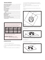
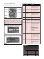
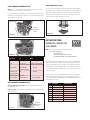
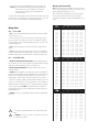
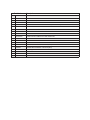
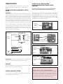
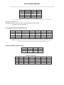
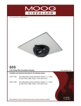
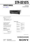
© 2011, Moog Videolarm, Inc. All Rights Reserved
QMR
QView™ Series Ceiling Mount Dome
www.videolarm.com
Installation and Operation Instructions for the following models:
QMRT2-70NA
Recessed tinted indoor/outdoor ceiling dome, with two (2) Day/Night cameras, 3-9mm auto-iris lens
QMRT4-70NA
Recessed tinted indoor/outdoor ceiling dome, with four (4) Day/Night cameras,
3-9mm auto-iris lens
Before attempting to connect or operate this product, please read these instructions completely. To be used with the 81-IN5409 Instruction Manual.
81-IN5258
01-31-2012
IMPORTANT SAFEGUARDS
1
Read these instructions.
2
Keep these instructions.
3
Heed all warnings
4
Follow all instructions.
5
Do not use this apparatus near water.
6
Clean only with damp cloth.
7
CAUTION
RISK OF ELECTRIC SHOCK
DO NOT OPEN
Do not block any of the ventilation openings. Install in accordance with the
manufacturers instructions.
8
9
SAFETY PRECAUTIONS
Cable Runs- All cable runs must be within permissible distance.
CAUTION: TO REDUCE THE RISK OF
ELECTRIC SHOCK, DO NOT REMOVE
COVER ( OR BACK). NO USER- SERVICEABLE PARTS INSIDE. REFER SEVICING
TO QUALIFIED SERVICE PERSONNEL.
Mounting - This unit must be properly and securely mounted to a supporting
structure capable of sustaining the weight of the unit.
Accordingly:
a. The installation should be made by a qualified installer.
b. The installation should be in compliance with local codes.
c. Care should be exercised to select suitable hardware to install the unit, taking into
account both the composition of the mounting surface and the weight of the unit.
10 Do not install near any heat sources such as radiators, heat registers, stoves, or other
apparatus ( including amplifiers) that produce heat.
11 Do not defeat the safety purpose of the polarized or grounding-type plug. A
polarized plug has two blades with one wider than the other. A grounding type
plug has two blades and a third grounding prong. The wide blade or the third
prong are provided for your safety. When the provided plug does not fit into your
outlet, consult an electrician for replacement of the obsolete outlet.
12 Protect the power cord from being walked on or pinched particularly at plugs,
convenience receptacles, and the point where they exit from the apparatus.
13 Only use attachment/ accessories specified by the manufacturer.
14 Use only with a cart, stand, tripod, bracket, or table specified by the manufacturer,
or sold with the apparatus. When a cart is used, use caution when moving the cart/
apparatus combination to avoid injury from tip-over.
15 Unplug this apparatus during lighting storms or when unused for long periods of time.
16 Refer all servicing to qualified service personnel. Servicing is required when the
apparatus has been damaged in any way, such as power-supply cord or plug is
damaged, liquid has been spilled of objects have fallen into the apparatus, the
The lightning flash with an arrowhead symbol,
within an equilateral triangle, is intended to
alert the user to the presence of non-insulated
“dangerous voltage” within the product’s
enclosure that may be of sufficient magnitude
to constitute a risk to persons.
Este símbolo se piensa para alertar al usuario a la presencia
del “voltaje peligroso no-aisIado” dentro del recinto de los
productos que puede ser un riesgo de choque eléctrico.
Ce symbole est prévu pour alerter I’utilisateur à la presence
“de la tension dangereuse” non-isolée dans la clôture de
produits qui peut être un risque de choc électrique.
Dieses Symbol soll den Benutzer zum Vorhandensein der
nicht-lsolier “Gefährdungsspannung” innerhalb der
Produkteinschließung alarmieren die eine Gefahr des
elektrischen Schlages sein kann.
Este símbolo é pretendido alertar o usuário à presença “di
tensão perigosa non-isolada” dentro do cerco dos produtos
que pode ser um risco de choque elétrico.
Questo simbolo è inteso per avvertire I’utente alla presenza
“di tensione pericolosa” non-isolata all’interno della
recinzione dei prodotti che può essere un rischio di scossa
elettrica.
apparatus has been exposed to rain or moisture, does not operate normally, or
has been dropped.
Be sure to periodically examine the unit and the supporting structure to make sure that the integrity
of the installation is intact. Failure to comply with the foregoing could result in the unit separating
from the support structure and falling, with resultant damages or injury to anyone or anything struck
by the falling unit.
UNPACKING
Unpack carefully. Electronic components can be
damaged if improperly handled or dropped. If an item
appears to have been damaged in shipment, replace
it properly in its carton and notify the shipper.
Be sure to save:
1 The shipping carton and packaging material.
They are the safest material in which to make future
shipments of the equipment.
2 These Installation and Operating Instructions.
SERVICE
If technical support or service is needed, contact us at
the following number:
TECHNICAL SUPPORT
AVAILABLE 24 HOURS
1- 800 - 554 -1124
The exclamation point within an equilateral
triangle is intended to alert the user to
presence of important operating and
maintenance (servicing) instructions in the
literature accompanying the appliance.
Este símbolo del punto del exclamation se piensa para
alertar al usuario a la presencia de instrucciones importantes
en la literatura que acompaña la aplicación.
Ce symbole de point d’exclamation est prévu pour alerter
l’utilisateur à la presence des instructions importantes dans
la littérature accompagnant l’appareil.
Dieses Ausruf Punktsymbol soll den Benutzer zum
Vorhandensein de wichtigen Anweisungen in der Literatur
alarmieren, die das Gerät begleitet.
Este símbolo do ponto do exclamation é pretendido alertar o
usuário à presença de instruções importantes na literatura
que acompanha o dispositivo.
Questo simbolo del punto del exclamaton è inteso per
avvertire l’utente alla presenza delle istruzioni importanti nella
letteratura che accompagna l'apparecchio.
Limited Warranty for Moog Videolarm Products
Moog Videolarm warrants these products to be free from defects in material or workmanship as follows:
PRODUCT CATEGORY
PARTS \ LABOR
All Enclosures and Electronics*
Five
Poles/PolEvators™/CamEvator
Three (3) Years
Warrior Series™/Q-View™/IR Illuminators
Five
(5) Years
SView Series™
Five
(5) Years **6 months if used in auto scan/tour operation
Controllers
Five
(5) Years
Power Supplies
Five
(5) Years
EcoKit
Three (3) Years
Accessory Brackets
Five
Liberty Dome
Three (3) Years
*DeputyDome™, NiteTrac™, Igloo Dome, PurgeDome™
Three (3) Years **6 months if used in auto scan/tour operation
(5) Years
(5) Years
During the labor warranty period, to repair the Product, Purchaser will either return the defective product, freight prepaid, or deliver it to Moog Videolarm
Inc. Decatur GA. The Product to be repaired is to be returned in either its original carton or a similar package affording an equal degree of protection with
a RMA # (Return Materials Authorization number) displayed on the outer box or packing slip. To obtain a RMA# you must contact our Technical Support
Team at 800.554.1124, extension 101. Moog Videolarm will return the repaired Product freight prepaid to Purchaser. Moog Videolarm is not obligated to
provide Purchaser with a substitute unit during the warranty period or at any time. After the applicable warranty period, Purchaser must pay all labor and/or
parts charges.
The limited warranty stated in these product instructions is subject to all of the following terms and conditions.
TERMS AND CONDITIONS
1. NOTIFICATION OF CLAIMS: WARRANTY SERVICE: If Purchaser believes that the Product is defective in material or workmanship, then written notice with an
explanation of the claim shall be given promptly by Purchaser to Moog Videolarm. All claims for warranty service must be made within the warranty period.
If after investigation Moog Videolarm determines the reported problem was not covered by the warranty, Purchaser shall pay Moog Videolarm for the cost of
investigating the problem at its then prevailing per incident billable rate. No repair or replacement of any Product or part thereof shall extend the warranty period
of the entire Product. The specific warranty on the repaired part only shall be in effect for a period of ninety (90) days following the repair or replacement of that
part or the remaining period of the Product parts warranty, whichever is greater.
2. EXCLUSIVE REMEDY: ACCEPTANCE: Purchaser’s exclusive remedy and Moog Videolarm’s sole obligation is to supply (or pay for) all labor necessary to repair any
Product found to be defective within the warranty period and to supply, at no extra charge, new or rebuilt replacements for defective parts.
3. EXCEPTIONS TO LIMITED WARRANTY: Moog Videolarm shall have no liability or obligation to Purchaser with respect to any Product requiring service during the
warranty period which is subjected to any of the following: abuse, improper use, negligence, accident, lightning damage or other acts of God (i.e., hurricanes,
earthquakes), modification, failure of the end-user to follow the directions outlined in the product instructions, failure of the end-user to follow the maintenance
procedures recommended by the International Security Industry Organization, written in product instructions, or recommended in the service manual for the
Product. Furthermore, Moog Videolarm shall have no liability where a schedule is specified for regular replacement or maintenance or cleaning of certain parts
(based on usage) and the end-user has failed to follow such schedule; attempted repair by non-qualified personnel; operation of the Product outside of the
published environmental and electrical parameters, or if such Product’s original identification (trademark, serial number) markings have been defaced, altered,
or removed. Moog Videolarm excludes from warranty coverage Products sold AS IS and/or WITH ALL FAULTS and excludes used Products which have not
been sold by Moog Videolarm to the Purchaser. All software and accompanying documentation furnished with, or as part of the Product is furnished “AS IS”
(i.e., without any warranty of any kind), except where expressly provided otherwise in any documentation or license agreement furnished with the Product. Any
cost associated with removal of defective product and installation of replacement product is not included in this warranty.
4. PROOF OF PURCHASE: The Purchaser’s dated bill of sale must be retained as evidence of the date of purchase and to establish warranty eligibility.
DISCLAIMER OF WARRANTY
EXCEPT FOR THE FOREGOING WARRANTIES, Moog Videolarm HEREBY DISCLAIMS AND EXCLUDES ALL OTHER WARRANTIES, EXPRESS OR IMPLIED,
INCLUDING, BUT NOT LIMITED TO ANY AND/OR ALL IMPLIED WARRANTIES OF MERCHANTABILITY, FITNESS FOR A PARTICULAR PURPOSE AND/OR
ANY WARRANTY WITH REGARD TO ANY CLAIM OF INFRINGEMENT THAT MAY BE PROVIDED IN SECTION 2-312(3) OF THE UNIFORM COMMERCIAL
CODE AND/OR IN ANY OTHER COMPARABLE STATE STATUTE. Moog Videolarm HEREBY DISCLAIMS ANY REPRESENTATIONS OR WARRANTY THAT
THE PRODUCT IS COMPATIBLE WITH ANY COMBINATION OF NON-Moog Videolarm PRODUCTS OR NON-Moog Videolarm RECOMMENDED PRODUCTS
PURCHASER MAY CHOOSE TO CONNECT TO THE PRODUCT.
LIMITATION OF LIABILITY
THE LIABILITY OF Moog Videolarm, IF ANY, AND PURCHASER’S SOLE AND EXCLUSIVE REMEDY FOR DAMAGES FOR ANY CLAIM OF ANY KIND
WHATSOEVER, REGARDLESS OF THE LEGAL THEORY AND WHETHER ARISING IN TORT OR CONTRACT, SHALL NOT BE GREATER THAN THE ACTUAL
PURCHASE PRICE OF THE PRODUCT WITH RESPECT TO WHICH SUCH CLAIM IS MADE. IN NO EVENT SHALL Moog Videolarm BE LIABLE TO PURCHASER
FOR ANY SPECIAL, INDIRECT, INCIDENTAL, OR CONSEQUENTIAL DAMAGES OF ANY KIND INCLUDING, BUT NOT LIMITED TO, COMPENSATION,
REIMBURSEMENT OR DAMAGES ON ACCOUNT OF THE LOSS OF PRESENT OR PROSPECTIVE PROFITS OR FOR ANY OTHER REASON WHATSOEVER.
TABLE OF CONTENTS
4. Remove the trim ring/dome assembly by pulling on the outside of the trim ring. Cable and Power Guidelines.............................................1, 11
Electrical Specifications................................................... 1
Housing Installation..........................................................1
Wiring............................................................................... 2
Camera Adjustment.......................................................... 2
Camera Focusing..............................................................2
Camera Settings
Black/White..................................................................2
Color.............................................................................3
Completion of Installation................................................. 3
NVT Instructions...............................................................3
Exploded View...................................................................5
Warranty Information........................................................ 6
Service and Safeguard Information.................................. 7
Troubleshooting................................................................ 8
The ring and dome are connected by three flat springs, which press against the side
of the housing and lock into (3) cutouts.
5. Run electrical cable and video leads into the housing through the conduit knock-out.
6. With the (3) support arms rotated to the inside, slide the housing into the pre-cut
hole (Figure 1).
Mounting Holes
Support Arm Holes
CABLE AND POWER GUIDELINES (Detailed info on Page 11)
This chart shows the proper current needed for power supplies for Q-View™
Figure 1
cameras. Use Class 2 Power only. Input voltage must be 24 VAC/VDC.
7. With the bottom flange pressed up against the ceiling, rotate the support arms to
CAMERAS
VOLTAGE
CURRENT
POWER
1 24 VAC/VDC 102mA 2.5W
the outside, the arms will fall to the back side of the ceiling. Tighten the (3) support
arm screws (Figure 2).
2 24 VAC/VDC 210mA 5W
3 24 VAC/VDC 331mA 7.9W
Support Arms Rotate Out
4 24 VAC/VDC 487mA 10.9W
Use the formula below to select the correct power supply for cameras connected
in parallel (positive to positive, negative to negative):
Total current for a 24 VAC system:
TOTAL CURRENT = (202mA x total number of cameras)
Note: 202mA is camera plus power supply
Figure 2
8. If the housing is going into a ceiling where the support arms will not work, secure
the housing by running bolts into the solid ceiling through the mounting holes in the
bottom flange (Figure 1).
HOUSING INSTALLATION
9. For added support, run support wires from a secure structure to the two slots
provided on the top of the housing (Figure 3).
1. Carefully remove all equipment from the box.
Support Wires
2. Place the 11 1/8" template provided with the unit at the desired location on the ceiling. Trace around the template, then cut a hole in the ceiling following the
trace lines. 3. Remove the desired conduit knock-out from the top of the QMR housing.
Figure 3
WIRING
CAMERA SETTINGS
1. Make the proper connections to the incoming power. The RED wire is POSITIVE (+),
the BLACK wire is NEGATIVE (-) (For reference purposes. Polarity is not important in
this unit). The GREEN wire, labeled Ground, is GROUND for VAC or VDC connections.
NOTE: To determine which camera is used in your unit, locate the serial number
on the inside of the housing. Match the two letter prefix with the corresponding
instructions included here for adjustments.
NOTE: Connect green ground wire to earth ground (metal conduit,metal stud, etc.)
2. Attach the BNC connectors to the video in.
SERIAL NUMBERS BEGINNING WITH YK
CAMERA ADJUSTMENTS
FIXED AND FIXED VARI-FOCAL LENSES. There are no user adjustable settings on
these units (Figure 7).
1. After completing installation of the housing, use the segmented arms to adjust each
camera to the desired viewing location (Figure 4).
BW Fixed and Vari-Focal
2. Once camera adjustments are made, place the dome back into position to be sure
cameras are not touching the inside of the dome. If any do, adjust until they are clear.
Figure 7
AUTO IRIS LENSES. The dip switches are factory set with AES off and backlight
compensation on (Figure 8). The auto iris is also set at the factory, but an adjustment
screw is included for use if needed. See page 10 for instructions on adjusting Auto Iris.
Figure 4
CAMERA FOCUSING
BW Auto Iris
1. Fine focusing:
Fixed Lens: Loosen the set screw in the lens mount and manually rotate the lens until
a clear picture is achieved. Once the focus is set, retighten the set screw (Figure 5).
Backlight
Compensation
Default On
Fixed lens
Set screw
Figure 8
Figure 5
Vari-Focal Lens: First, adjust the Magnification Lock Screw to the desired
magnification (telephoto to wide angle). Tighten the Lock Screw. Next, adjust the
Focus Lock Screw until a clear picture is achieved. Tighten the Lock Screw (Figure 6).
Magnification lock screw
Focus lock screw
Fixed iris
vari-focal lens
Figure 6
Auto Iris Lens:
NOTE: THE AUTO IRIS LENS IS SET AT THE FACTORY.
• IF YOU EXPERIENCE VIDEO TOO LIGHT OR DARK AUTO IRIS ADJUSTMENT MAY
BE NEEDED.
SEE THE TROUBLESHOOTING SECTION FOR
ADJUSTMENT INFORMATION.
AES Default Off
Auto Iris
adjustment
screw
MC CAMERA DIP SWITCH SETTINGS CHART
SERIAL NUMBERS BEGINNING WITH MC
The operational settings for the camera are defined by ten dip switches located on the
PC Board (Figure 9). Moving the switches to the on position will activate each setting.
Factory defaults are pictured below (Figure 10 and 11).
SWITCH
SETTING
DEFINITION
1
Flickerless Mode
2
BLC (Back Light
Hi-Res Color, Fixed and Vari-focal fixed lenses
Factory
Use Only
Dip Switches
Auto Iris
adjustment
screw
Connection to
Power Board
Compensation)
3
MIRIS (Manual/
Electronic Iris
DO NOT
ADJUST
Figure 9
4
GAMMA
5
AGCMAX
FACTORY DEFAULT FIXED AND FIXED VARI-FOCAL LENSES:
Dip Switches 5 and 7 on, all others off.
Helps prevent an object from being
washed out when the object is
directly in front of a light source.
When the switch is in the on position
the auto iris lens controls the amount
of light on the chip. If in the off
position the light level is controlled
electronically.
Helps balance the contrast in the
picture. (auto/gain control)
NOTE: Dip switches are factory pre-set for optimum performance. In certain
specific instances it may be necessary to adjust one or more settings. Consult a
qualified technician before making any adjustments. A Dip Switch settings chart is available on the next page.
Setting this switch to "On" and switch
3 (MIRIS) to "Off" will help to reduce
the flicker in fluorescent lights.
(Automatic White
6
Balance Control)
AW1
7
AW2
8
AW3
9
AEREF
10
AEME
Allows day/night cameras to switch to
b/w in low light conditions, also helps with
low light conditions in standard and hi-res
cameras.
Used to help improve the color quality
of the camera picture under different
lighting conditions. The Factory
Default is Switch 7 "ON", switches 6
and 8 "OFF".
NOTE: ANY ADJUSTMENTS TO
THESE SETTINGS SHOULD ONLY
BE MADE BY A QUALIFIED CCTV
TECHNICIAN
See examples below to help with any
adjustments.
Figure 10
This sets the electronic convergence
level. In the "off" position the level is
set to 100 IRE; in the "on" position
the user can set the level. Not used
with auto Iris.
FACTORY DEFAULT AUTO IRIS LENSES:
Dip Switches 3, 5 and 7 on, all others off.
With this switch in the "On" position
users can manually adjust the shutter
speed and gain using other switches See the tables below for specific
settings.
Figure 11
SHUTTER SPEED
Flickerless (1)
BLC (2)
MIRIS (3)
Shutter Speed
On Off Off 1/100 Sec.
Off On Off 1/60 Sec.
GAIN
MIRIS (3)
AEREF (9)
AGCMAX (5)
Gain
On Off Off 0dB
On On Off 6dB
On Off On 12dB
On On On 18dB
COMPLETION OF INSTALLATION
SERIAL NUMBERS BEGINNING WITH CB
NOTE: This hi-res color camera uses a 1/4" chip and a 3-6mm auto iris lens. It is
comparable to a 1/3" chip using a 4-9mm auto iris lens.
The operational settings are defined by four dip switches located on the side of the PC
Board (Figure 12 and 13). Moving the switches to the UP position will activate specific
settings. Refer to the chart below.
Once all connections and adjustments have been made reattach the trim ring/dome
assembly by pressing in and sliding the three flat springs into the housing (Figure 15). Make sure the springs are aligned with the three spring slots. You will feel all three
springs snap into place when the dome is correctly secured into place. Rotate the
dome for final proper positioning of the liner and camera.
Dip Switches
Auto Iris
Adjustment
Screw
Figure 15
Figure 12
NVT INSTRUCTIONS
UNSHIELDED TWISTED PAIR
VIDEO WIRING
NOTE: The customer must purchase the Video Transceiver from
NVT. Part numbers are:
• NV-212A (500 ft.)
* NV-213A or NV-213A-M (1000 ft.)
• NV-652R, NV-862R, or NV-1662R (3000 ft.)
Figure 13
Dip Switch
UP
DOWN
1
(Iris)
Auto Iris On
Position for Fixed Lens
2
(Flickerless)
Shutter speed
3 (Back Light
ON
Normal
fixed at 1/100 sec.
Normal
Compensation
4
(Synch Mode)
Internal Synch
Line Lock Mode
SERIAL NUMBERS BEGINNING WITH CT
FIXED AND FIXED VARI-FOCAL LENSES. There are no user adjustable settings on
these units (Figure 14)
AUTO IRIS LENSES: The auto iris can be adjusted if needed. See the Troubleshooting
section for instructions.
Auto Iris
adjustment
screw
Figure 14
The cameras included in the Q-View™ series have the option of transmitting video
signals to NVT receivers via unshielded twisted pair cable. You must purchase the
receiver separately. Instructions for connecting the receiver end of the unshielded
twisted pair cable will be included with the NVT receiver. Following are instructions
for connecting the unshielded twisted pair cables to the RJ45 (Cat. 5) cable running
outside your housing.
1. Video for all four cameras is contained in the one RJ45 (Cat. 5) cable. An RJ45
female coupling is provided so that all connections can be made with an RJ45
connector. The following is the wiring diagram for the four twisted pair wires that are
included with the Cat. 5 cable.
PIN
WIRE COLOR
CAMERA NUMBER
1
White/Green
Camera 1 +
2
Green
Camera 1 -
3
White/Orange
Camera 2 +
6
Orange
Camera 2 -
5
White/Blue
Camera 3 +
4
Blue
Camera 3 -
7
White/Brown
Camera 4 +
8
Brown
Camera 4 -
2. Connect the other end of the unshielded twisted pair cable to the NVT receiver. CAUTION: The unshielded twisted pair video signal is polarity dependent. The
positive video wire for each camera MUST be connected to the positive terminal on the NVT receiver, and negative MUST be connected to negative.
3. When using unshielded twisted pair cable you DO NOT need the BNC connector. All
four BNC connectors are provided inside the housing for testing purposes. Be sure that
there is no video connection other than the unshielded twisted pair cable.
Measure your wire distance
Note: All NVT quoted distance specifications include any coax in the
run. It is recommended that the wire distance be measured to ensure
that the capability of the NVT product is correct.
Wire resistance may be measured with an ohm-meter by shorting
the two conductors together at the far end, and measuring the
loop-resistance out and back. Compare your readings with the charts
below.
Cable
Wiring Notes
Distance
250 ft
Wire — What to DO
300 ft
1. DO use point-to-point Unshielded Twisted Pair wire, gauge 24 or thicker, stranded
or solid, Category 2, 3, 4, or 5.
500 ft
400 ft
600 ft
800 ft
2. The video signal may co-exist in the same wire bundle as other video, telephone,
data, control signals, or low-voltage power. It is also OK to run NVT video signals in or
near electromagnetic fields (in accordance with National Electrical Code, local, or other
local safety requirements).
1000 ft
3. DO measure the wire distance. Use only transceivers that are designed for that
distance.
2500 ft
4. DO make sure the pair of wires carrying the video signal is sent as a twisted pair
(e.g. the blue-white/white-blue wires twisted together as a pair), not a “split-pair” (e.g.
blue-white conductor, part of one pair/orange-white conductor, part of another pair).
4000 ft
Wire — What NOT to DO
1. Do not use shielded twisted pair wire. It will severely degrade the distance performance. Short runs may be used with some signal degradation (for example
elevator traveler cables). Multi-pair wire with an overall shield is OK.
2. Do nOt use un-twisted wire. It will reduce the NVT product’s inherent
interference immunity.
3. DO NOT allow your installation to have “bridge-taps”, loading coils, talk-battery, or
MOV type protectors. Bridge-taps are where a twisted pair is connected to two twisted
pairs (such as an extension phone at home). Bridge-taps cause reflections as the
signal propagates, resulting in “ghosts” in the video image, and are to be avoided.
4. If the phone company is providing the cable runs between buildings, make sure it’s
“dry copper” i.e. it should have none of the following: dial-tone, 48 volts, loading coils,
bridge-taps, switching, or long paths to the phone company’s central office and back.
5. Due to near-end crosstalk, DO NOT send a transmit and a receive signal in the
same wire bundle. Exceptions: Less than 1,000 ft (300m), or Category 5 cable, up to
2,000 ft (600m) are OK.
6. DO NOT send “Up-the-Coax” Pan/Tilt/Zoom signals through active (amplified) NVT
transceivers.
!
!
7. For safety, never put NVT signals in the same conduit as high-voltage
wiring.
8. WARNING — to reduce a risk of fire or electrical shock, do not expose
this product to rain or moisture.
1250 ft
1500 ft
1750 ft
2000 ft
3000 ft
3500 ft
5000 ft
6000 ft
8000 ft
Cable
Unshielded Twisted-Pair Wire Gauge (AWG)
18
3
4
5
6
8
10
13
16
19
23
26
32
39
45
52
65
78
104
W
W
W
W
W
W
W
W
W
W
W
W
W
W
W
W
W
W
19
4
5
6
8
10
13
16
20
24
28
32
40
48
56
64
80
95
127
W
W
W
W
W
W
W
W
W
W
W
W
W
W
W
W
W
W
20
5
6
8
10
12
16
20
25
30
35
40
49
59
69
79
99
119
158
W
W
W
W
W
W
W
W
W
W
W
W
W
W
W
W
W
W
22
8
10
13
16
19
25
32
40
48
55
63
79
95
111
127
158
190
253
W
W
W
W
W
W
W
W
W
W
W
W
W
W
W
W
W
W
24
13
16
21
26
31
42
52
65
78
91
104
131
157
183
209
261
313
418
W
W
W
W
W
W
W
W
W
W
W
W
W
W
W
W
W
W
Unshielded Twisted-Pair Wire Gauge (AWG)
Distance
18
19
20
22
24
75 m
3 W
4 W
5 W
8 W
13 W
100 m
4 W
5 W
6 W
10 W
17 W
125 m
5 W
7 W
8 W
13 W
21 W
150 m
6 W
8 W
10 W
16 W
26 W
200 m
9 W
10 W
13 W
21 W
34 W
300 m
13 W
16 W
19 W
31 W
51 W
400 m
17 W
21 W
26 W
42 W
69 W
500 m
21 W
26 W
32 W
52 W
86 W
600 m
26 W
31 W
39 W
62 W
103 W
750 m
32 W
39 W
49 W
78 W
129 W
900 m
38 W
47 W
58 W
94 W
154 W
1000 m
43 W
52 W
65 W
104 W
171 W
206 W
1200 m
51 W
63 W
78 W
125 W
1500 m
64 W
78 W
97 W
156 W
257 W
1800 m
77 W
94 W
117 W
187 W
309 W
2400 m
102 W
125 W
156 W
249 W
411 W
Cable
Unshielded Twisted-Pair Wire Gauge (mm)
1.0
0.8
0.7
0.6
75 m
3
5
6
9
13 W
100 m
4
7
9
12
18 W
125 m
6
8
11
15
22 W
150 m
7
10
13
18
27 W
200 m
9
13
17
24
36 W
300 m
13
20
26
36
54 W
400 m
18
27
35
48
72 W
500 m
22
33
43
60
90 W
600 m
26
40
52
72
108 W
750 m
33
50
65
89
135 W
900 m
40
60
78
107
162 W
1000 m
44
66
86
119
179 W
1200 m
53
80
104
143
215 W
1500 m
66
100
130
179
269 W
1800 m
79
120
155
215
323 W
2400 m
106
159
207
286
431 W
Distance
0.5
MR7 Exploded Diagram and Replacement Parts List
1
2
3
4
5
Part Number
1
Description
RPOD01
PC Board and Input cables video/power
RPOD01-NVT
PC Board and Input cables video/power with NVT
2
RPQF02
multi CAMERA metal base BRACKET
3
RPQF03
camera bracket and hardware
RPQF03-20NA
camera bracket and hardware - (20 na models)
1A
4
RPQF04
plastic articulated bracket
5
RPQF20NF3
hi-res b&w 3.6 fixed lens
RPQF20NA
hi-res b&w 4-9mm auto iris varifocal
RPQF50NF3
hi-res color 3.6 fixed lens
RPQF50NA
hi-res color 4-9mm auto iris varifocal
RPQF70NA
hi-res day/night 4-9mm auto iris varifocal
RPQMR01
packet assembly
N/S
6
RPMR7050
white trim ring assembly
7
RCMR7C
clear replacement capsule (MR7)
RCMR7T
tinted replacement capsule (MR7)
8
RPQD08
set of (4) spacers
9
RPQD07
bracket assembly
10
RPMR7020
(Q)MR7 support arms
11
RPMR7010
(Q)MR7 housing assembly
TROUBLESHOOTING
If you experience problems with the camera picture please check these simple
troubleshooting procedures for possible solutions before calling technical
support.
STATIONARY OR SCROLLING HORIZONTAL LINES ON
SCREEN
GROUND
LOOPS
Generally a horizontal line on screen, whether moving or stationary, means you have a
ground loop problem. The video shield should only be connected to ground through the
monitor or other electronic equipment that uses the video signal. Connecting the video
shield to ground at the camera will create a ground loop, which may interfere with the
video signal (See Figure A). This should not damage the camera, but the video signal
may become unusable. A ground loop problem will cause a dark horizontal bar to slowly
“scroll" through the picture. To solve this problem, remove all ground connections from
the video connection EXCEPT for the ground at the terminating end of the video signal.
The video termination should be a 75-ohm impedance, standard in monitors and
other video equipment. If the video signal goes to more than one piece of equipment,
a monitor and multiplexer input for instance, insure that one and only one piece of
equipment terminates the video signal with 75 ohms; otherwise the image will be
degraded and may appear to be unusually dim.
Power A
The auto iris lens is set at the factory. If you experience video too light or
dark you can manually adjust using the auto iris adjustment screw.
If there is low or no color the Auto Iris is too open, if the picture is dark or grainy in
good conditions the Auto Iris is too closed. To adjust the auto iris lens, first locate the
AUTO IRIS ADJUSTMENT SCREW on the camera PC board. Using a small insulated
screwdriver (blade width of from 1/16" to 3/32"), adjust the control. Turning the control
CLOCKWISE opens the iris, making the image brighter. Turning the control COUNTER
CLOCKWISE closes the iris, making the image darker.
SERIAL NUMBER YK CAMERAS
Auto Iris
Adjustment
Screw
Figure B
SERIAL NUMBER MC CAMERAS
Power Supply
Camera
Assembly
PICTURE IS CLEAR, LOW OR NO COLOR;
PICTURE IS DARK OR GRAINY IN GOOD LIGHTING
CONDITIONS
Primary
Power
Auto Iris
Adjustment Screw
Power B
Figure C
Video Signal
(Ground Return)
SERIAL NUMBER CB CAMERAS
Monitor
Video Shield
Figure A Ground Loop
Auto Iris
Adjustment
Screw
Figure D
SERIAL NUMBER CT CAMERAS
IMPORTANT NOTE: If you have removed the ground loop and the horizontal line still
remains on screen call Videolarm technical support for further information.
LINE LOCK
All cameras are all shipped from the factory with the line lock function disabled. If your
application requires Line Lock contact Moog Videolarm.
AUTOMATIC BROWN OUT FEATURE
The camera includes an automatic brown out feature which is activated whenever the
incoming voltage drops below 10 VAC or VDC.
Auto Iris
Adjustment
Screw
Figure E
IMPORTANT NOTE ON AUTO IRIS ADJUSTMENT:
WHEN ADJUSTING, USE A SMALL, INSULATED SCREWDRIVER. The auto iris
adjustments are very sensitive. Use gentle pressure when turning. To adjust, turn
either clock-wise or counter-clockwise no more than one degree at a time. Check
the monitor after each turn to determine is the desired brightness and color have
been obtained. When the adjustment is satisfactory, place a hand over the lens to
block out all light. Quickly remove the hand to be sure the iris reacts.
NVT TROUBLESHOOTING
If you are experiencing problems, attempt to simplify your setup. Test each cable
segment separately. For example, test the camera and monitor together without the
other equipment. Then add in the NVT transceivers, back-to-back. Test each segment
of a long cable-run independently. Attempt to isolate the problem.
Below are problems that may be encountered. If the suggestions below are not helpful,
or the recommendations are not effective, please call NVT’s customer support. NVT
customer support can be reached 8:00 AM to 5:30 PM PST at (800) 959-9870 or at
(+1) (650) 562-0600.
FAINT OR BLURRY PICTURE; LITTLE OR NO COLOR
Possible causes include:
1. Shielded twisted-pair cable. Verify that the wire is unshielded twisted-pair cable.
Multi-pair cable with an overall shield is OK.
2. Longer wire distance than expected. Be sure to include any coax cable that’s part of
this distance. Verify end-to-end connectivity with an ohm meter. Measure the distance
by disconnecting the transceivers, shorting the far end, reading the loop’s resistance at
the near end. See above for ohm vs. distance ratings. If necessary, replace transceivers
with correct models specified for this distance.
3. Incorrect distance equalization setting. Adjust the equalization controls) with a mini
screwdriver (NV-652R, NV-862R or the NV-1662R). If the transmitter is an NV-653T,
verify correct equalization switch setting.
If the voltage is greater than 1/2 volt, use an amplified receiver, such as the NV-652R,
NV-862R, or NV-1662R.
Alternately, remove the ground at one end (usually at the camera end). Be sure that
floating the camera conforms to local/regional and National Electrical Codes.
4. Check for crosstalk from a second video path. Disconnect all other video sources. If
the problem goes away, check for a split-pair or un-twisted wire.
FAINT STRIPES GLIDING UP OR DOWN THE SCREEN
These are caused by crosstalk from a second video path, or with ground-loops in
installations employing passive models at both ends.
1. To identify, disconnect all other video signals temporarily. If the interference goes
away, check the wire to make sure the signal is traveling through a twisted pair. Is
two-way video being sent more than 1,000 ft (300m) over Category 2 or 3 wire? If so,
the send and receive signals may need to go in separate jacketed cables, or upgrade
to Category 5 wire.
2. Next, check for ground loops. See #3 above.
NO POWER LIGHT ON THE NVT UNIT
Check the blue “power” LED on powered NVT units. If the light is not on, the receiver is
not getting power. Re-check the power source and connections.
If the green LED is on but the power LED is off, check that the power supply is floating.
Grounding one side of the power input may cause this condition.
4. Poor connection at a punch-block, splice, or coax cable. Re-check using the
method described in #2 above, or use a wire test set.
5. Short between conductors of the twisted-pair. Use an ohm meter to locate the short.
NO GREEN LIGHT, NO VIDEO
6. Transient protection devices employing metal-oxide varistors. Use carbon blocks,
gas-discharge tubes, or NVT transceivers with built-in protection.
The NV-652R, NV-862R or NV-1662R series receiver/hub is not detecting a video
signal. There is an open or shorted connection. Use a multimeter to locate the fault.
7. Check the camera. Are the focus and iris set correctly? Verify with portable monitor.
EXTREMELY FAINT PICTURE
Only faint shadows of the original picture are visible. One of the twisted pair conductors
is open or the wires are shorted together. Check with an ohm meter.
OVER-SATURATED COLORS; HIGH CONTRAST GRAINY PICTURE; TOO BRIGHT,
TORN PICTURE
Adjust the distance equalization as necessary. Verify that the monitor has a 75
termination, not in “loop-through”.
WON'T SYNC; WIDE, WHITE JAGGED AREAS
GHOSTS
Faint shadows of the original signal shifted to the right. This is caused by an
impedance mismatch along the wire. Verify that the monitor is terminated with 75 (not
in “loop-through”.) Check that all wire is unshielded twisted pair. The high-frequency
wire impedance should be 100. Check for bridge-taps (see below) either by inspecting
wiring closet connections, or, if available, using a “Time-Domain Reflectometer”
(T.D.R.), sometimes called a “cable tester”.
If the faint shadows are not copies of the original picture, but from the picture of some
other camera, check for crosstalk:
Is any portion of the wire un-twisted?
Are the signals from two cameras split between two pairs?
Is there a short between a conductor of one signal and a conductor of another?
Looks like a scrambled Cable TV signal. Check polarity.
WON'T SYNC; TORN PICTURE
1. Make sure that you are using unshielded twisted pair wire.
2. Check distance equalization settings.
3. For installations with passive (non-amplified) transceivers at both ends, check for
ground loops. This may be done with an AC Voltmeter, as shown below:
Bridge Tap
13A
NV-2
Camera
AC Voltmeter
NV-21
3A
Monitor
CABLE AND POWER GUIDELINES
This chart shows the proper current needed for power supplies for Q-View Series cameras. Use Class 2 Power only. Input voltage must be 24 VAC/VDC.
CAMERAS
CURRENT
POWER
1
VOLTAGE
24 VAC/VDC
102mA
2.5W
2
24 VAC/VDC
210mA
5W
3
24 VAC/VDC
331mA
7.9W
4
24 VAC/VDC
487mA
10.9W
Use the formula below to select the correct power supply for cameras connected in parallel (positive to positive, negative to negative):
Total current for a 24 VAC system:
TOTAL CURRENT = (202mA x total number of cameras) Example: 202mA x 5 total cameras = 1010mA
Note: 202mA is camera plus power supply
Power Supply Cable Maximum Length (feet/meters)
CAMERAS
TOTAL LOAD
18 AWG
16 AWG
1
2.5W
POWER SUPPLY
24 VAC/VDC
24 AWG
1718/523
22 AWG
2733/833
6909/2106
10985/3348
2
5W
24 VAC/VC
834/254
1327/404
3356/1023
5335/1626
3
7.9W
24 VAC/VDC
529/161
842/256
2129/649
3385/1032
4
10.9W
24 VAC/VDC
359/109
572/174
1447/441
2300/701
NOTE: The above table is based on a "worst-case" power supply. Using a regulated or switching power supply can increase your cable
distance. Videolarm recommends using our PS24 power supply, or a CSA/UL listed Class 2 power supply.
Video Cable Maximum Length (feet/meters)
Cable Type
RG-59
RG-6
RG-11
Wire Gauge
23 AWG*
18 AWG*
16 AWG*
Max. Length
750/229
1500/457
2000/610
* Copper clad steel core, 95% braided shield
Maximum Length (feet/meters)
AWG
250/76
500/152
1000/305
1500/457
2000/610
18
3Ω
6Ω
13Ω
19Ω
26Ω
3000/914
40Ω
20
5Ω
10Ω
20Ω
30Ω
40Ω
59Ω
22
8Ω
17Ω
33Ω
48Ω
66Ω
99Ω
24
13Ω
26Ω
52Ω
78Ω
108Ω
163Ω
Product Registration/Warranty
Thank you for choosing Moog Videolarm. We value your patronage and are solely committed to providing you with the highest
quality products available and superior customer service. Should a problem arise, rest assure that Moog Videolarm stands behind its products by offering impressive warranty plans: 3 Years on all Housings, Poles, Power Supplies, and Accessories and 5 Years on camera systems (SView, QView, Warriors), and InfraRed Illuminators.
Register Your Products Online
Take a few moments and validate your purchase via the Online Product Registration Form at
www.videolarm.com/productregistration.jsp
Register your recent Moog Videolarm purchases and benefit from the following:
• Simple and Trouble-Free RMA process
• Added into customer database to receive product updates / news
• Eliminate the need to archive original purchase documents:
Receipts, Purchase Orders, etc…