1
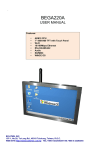
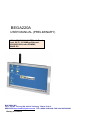
BEGA220A
USER MANUAL (PRELIMINARY)
ARM 9 CPU,7” 800X480 TFT with Touch
Panel, Wi-Fi, 10/100Mbps Ethernet,
RS232/485/422,Audio,SD/MMC,
WINCE OS
BOLYMIN, INC.
13F-1, No.20, Ta-Long Rd., 40310 Taichung, Taiwan, R.O.C.
WEB SITE:http://www.bolymin.com.tw TEL:+886-4-23293029 FAX:+886-4-23293055
History of Version
Version
01
BEGA220A USER MANUAL preliminary
Contents
NEW VERSION
-2-
Date
Note
2010/04/30
SPEC.
CONTENTS
Chapter1
General Information
1.1
1.2
1.3
Chapter2
介紹
1.1.1
1.1.2
規格
1.2.1
1.2.2
1.2.3
機構
1.3.1
包裝清單
外觀介紹
系統方塊圖
主機規格
Wi-Fi 規格
主機機構尺寸
BEGA220A 安裝
2.1 電源安裝
2.2 SD/MMC Card 使用方法
2.3 Host USB 使用方法
2.4 有線網路安裝設定
2.5 Wi-Fi 安裝設定
2.6 Communication Bus 使用方法
2.6.1 Communication Bus 腳位定義
2.6.2 Serial Port Test
2.6.2.1 Serial Port 安裝
2.6.2.2 Serial Port 測試步驟
2.6.3 Device USB 安裝
2.6.4 Speaker 安裝
2.7 ADC_GPIO Bus 使用方法
2.7.1 ADC_GPIO Bus 腳位定義
2.7.2 GPIO 測試
2.7.3 ADC 測試
2.7.3.1 ADC 測試線路接法
2.7.3.2 ADC 測試步驟
Chapter3
BEGA220A Programming Guide
3.1
Transfer File Between BEGA220A and PC
3.1.1 Connect PC and BEGA220A
3.1.2 Transfer File
3.2 Programming for BEGA220A
3.2.1 Setup Development Environment
3.2.2 Create New Project
3.3 Serial Port Control
3.3.1 Overview
3.3.2 Serial Port Control-CSerialPort Class
4.3.2.1 Basic concept of class CSerialPort
4.3.2.2 Member function of class CSerialPort
4.3.2.3 How to catch the receive message
3.3.3 Example Code
3.4 GPIO Control
3.4.1 How to Control GPIO for BEGA220A
3.4.2 GPIO Control Function for BEGA220A
3.4.3 Definition of GPIO Index
3.5 A/D Converter and Backlight Adjustment
3.5.1 Overview
3.5.2 Control Function of A/D Converter
3.5.3 Function about Backlight Adjustment
BEGA220A USER MANUAL preliminary
-3-
Chapter 1 General Information
摘要
這章節提供 BEGA220A 的基本資訊
包含部份:
1.1 介紹
1.2 規格
1.3 機構
BEGA220A USER MANUAL preliminary
-4-
1.1 INTRODUCE
Order Information
Part No.
RS-485 RS-422
BEGA220A
☆
BEGA220A1
☆
BEGA220A2
☆
BEGA220A3
☆
WLAN
20 PIN EXT BUS(IOX12,ADCX6)
☆
☆
☆
BEGA220A4
☆
BEGA220A5
☆
BEGA220A6
☆
BEGA220A7
☆
☆
☆
☆
☆
☆
1.1.1 PACKAGE LIST
z
z
z
z
BEGA220A
Female USB to mini USB cable with 20cm length (CB04P201LC01$)
220 communication cable with 3M 40 pin connector and
length100cm(CB40P1000LC01$ )( only on sample stage)
CD for user manual and ulitity software
BEGA220A USER MANUAL preliminary
-5-
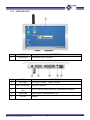
1.1.2 APPEARANCE
NO.
ITEM
DESCRIPTION
1
Touch panel
NO.
ITEM
2
DC Jack
3
ADC_GPIO Bus
GPIOx12, ADCx6。
4
Communication
Bus
SPI x1, Device USB, RS232x3, RS488/422x1(Option)
5
Host-USB
6
RJ-45
To operate WinCE system.
DESCRIPTION
DC Plug:φ2.5mm
Power: 12V/3A
USB mouse, USB keyboard…etc.
Internet
BEGA220A USER MANUAL preliminary
-6-
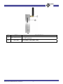
NO.
ITEM
7
WiFi antenna socket
8
SD Card
DESCRIPTION
For WiFi antenna
SD or MMC Card (Max. 4GB)
BEGA220A USER MANUAL preliminary
-7-
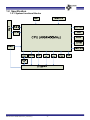
1.2 Specification
1.2.1 System functional blocks
BEGA220A USER MANUAL preliminary
-8-
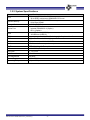
1.2.2 System Specifications
Parameter
GPIO
Specification
Samsung S3C2416X 400MHz
32 bit RISC architecture ARM926EJ CPU core
16-bit 64MB/133MHz DDR2 memory
512K Byte SRAM
2GB NAND Flash
2 wire RS232 x 3
Isolated RS485/422 x1(Option)
SPI x1(Option)
1x USB device (USB2.0)
1XUSB host (USB1.0)
Support programmable 12 x IO sharing with Key board interface
ADC
Support 6 x channel 12 bit high speed A/D converter
LAN
High performance 16-bit 10/100 Ethernet controller
Audio
Dual channels 2 watts speaker output
Wi-Fi
IEEE 802.11b/g,Wi-Fi compliant
OS
WinCE 5.0(default)
CPU
System Memory
Storage Device
Series Port
USB
LCD Size
7” TFT LCD
LCD Resolution
800x480
LCD Brightness
400 cd/m²
Power Supply
DC9V~DC28V
Operating Temperature
-20℃ ~ +70℃
BEGA220A USER MANUAL preliminary
-9-
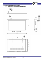
1.3 Mechanical specifications
1.3.1 Mechanical specifications of module
BEGA220A USER MANUAL preliminary
- 10 -
Chapter 2 BEGA220A 安裝測試
摘要
這章節提供 BEGA220A 的硬體安裝資訊
包含部份:
2.1 電源安裝
2.2 SD/MMC Card 使用方法
2.3 Host USB 使用方法
2.4 有線網路安裝設定
2.5 Wi-Fi 安裝設定
2.6 Communication Bus 使用方法
2.7 ADC_GPIO Bus 使用方法
BEGA220A USER MANUAL preliminary
- 11 -
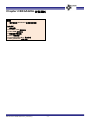
2.1 Connect power
Use a DC adaptor of φ2.5 / DC12V/3A into the DC jack and contact with a power of 110/200V
AC to socket. After connection is done, BEGA220A will boot up.
DC Plug_in φ2.5
BEGA220A USER MANUAL preliminary
- 12 -
2.2 SD/MMC Card
As shown in the following photo, plug in the SD/MMC card.
on the SD card to release it.
The display as below when you insert SD/MMC Card:
BEGA220A USER MANUAL preliminary
- 13 -
To remove a SD/MMC card, push
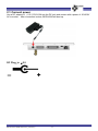
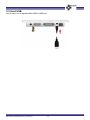
2.3 Host USB
Use a trans. line to transfer MINI USB to USB port.
BEGA220A USER MANUAL preliminary
- 14 -
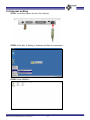
2.4 Internet setting
STEP1: Insert the internet line into the LAN port.
STEP2: Click Star Æ Setting Æ Network and Dail-up connections.
STEP3: Click DM9ISA1
BEGA220A USER MANUAL preliminary
- 15 -
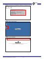
STEP4: Set specify an IP address or obtain an IP address via DHCP.
STEP5: Start to use internet.
STEP6: Input an address.
BEGA220A USER MANUAL preliminary
- 16 -
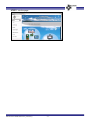
STEP7: Into the page.
BEGA220A USER MANUAL preliminary
- 17 -
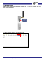
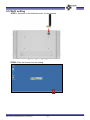
2.5 Wi-Fi setting
STEP1: As shown in the following photo, fix the antenna.
STEP2: Click the internet into the setting.
BEGA220A USER MANUAL preliminary
- 18 -
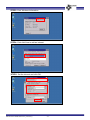
STEP3: Click Wireless Information.
STEP4: Click Add New to add an internet.
STEP5: Set the internet and click OK.
BEGA220A USER MANUAL preliminary
- 19 -
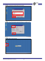
STEP6: Choose the internet and click connect.
STEP7: Click IP Information and click Renew to update an IP.
STEP8: Start to use internet.
BEGA220A USER MANUAL preliminary
- 20 -
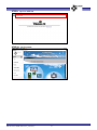
STEP9: Input an address.
STEP10: Into the page.
BEGA220A USER MANUAL preliminary
- 21 -
2.6 Communication Bus
2.6.1
Communication Bus
BEGA220A USER MANUAL preliminary
- 22 -
2.6.2
Serial Port Test
BEGA220A supports three sets of RS232 and one set of RS485 (option) or one set of RS422
(option).
2.6.2.1 Connect Serial Port to PC
1st set of RS232 (Debug Port)(only for update)- Connect 1st set of RS232 to DB9 female
connector as shown on below chart, and connect to COM port of PC. This port is defaulted
to a debug port and not for external use. Its signal level is at ±12 volt.
Table of 1st RS232 Pin Assignment
RS232 DB9 Female
BEGA220A
Pin No Pin Name Pin No Pin Name
1
DCD
—
—
2
3
TD
RD
8
28
TXD1T
RXD1T
4
DTR
—
—
5
6
7
8
GND
DSR
CTS
RTS
27
—
29
9
GND
—
CTS1T
RTS1T
9
RI
—
—
2nd set of RS232 (COM3)- Connect 2nd set of RS232 to DB9 female connector as shown
on below chart, and connect to COM port of PC. This port is defaulted to COM3 with a
signal level is at ±12 volt.
BEGA220A USER MANUAL preliminary
- 23 -
Table of 2nd RS232 Pin Assignment
RS232 DB9 Female
BEGA220A
Pin No Pin Name Pin No Pin Name
1
DCD
—
—
2
3
TD
RD
13
33
TXD3T
RXD3T
4
DTR
—
—
5
6
7
8
GND
DSR
CTS
RTS
32
—
—
—
GND
—
—
—
9
RI
—
—
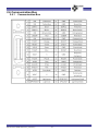
3rd set of RS232(COM4) - Connect 3rd set of RS232 to DB9 female connector as shown on
below chart, and connect to COM port of PC. This port is defaulted to COM4 with a signal
level is at ±12 volt.
Table of 3rd RS232 Pin Assignment
RS232 DB9 Female
BEGA220A
Pin No Pin Name Pin No Pin Name
1
DCD
—
—
2
3
TD
RD
11
31
TXD2T
RXD2T
4
DTR
—
—
5
6
7
8
GND
DSR
CTS
RTS
30
—
—
—
GND
—
—
—
9
RI
—
—
BEGA220A USER MANUAL preliminary
- 24 -
RS422 (Option)(COM1)- Use software to set COM 1. Signal level is at ±12 volt. Connect
with a device for testing or use a transfer board of RS232 to connect with PC for testing.
Table of RS422 Pin assignment
Pin No
Pin Name
35
A-422R15
16
A-422R+
A-485T+
36
A-485T-
34
GND2
*RS422 and RS485 cannot operate in the same time.
*Connect PIN14 to PIN12 and PIN12 to PIN 34 if do not need isolate.
Connect PIN14 and PIN34 to another power of 4.75~5.25V if need isolate.
RS485 (Option)(COM1) - Use software to set COM 1. Signal level is at ±12 volt. Connect
with a device for testing or use a transfer board of RS232 to connect with PC for testing.
Table of RS485 Pin assignment
Pin No
Pin Name
37
GND2
16
36
A-485T+
A-485T-
*RS422 and RS485 cannot operate in the same time.
*Connect PIN14 to PIN12 and PIN12 to PIN 34 if do not need isolate.
Connect PIN14 and PIN34 to another power of 4.75~5.25V if need isolate.
BEGA220A USER MANUAL preliminary
- 25 -
2.6.2.2 Serial Port test
Upon completion of serial connection of BEGA220A to PC, users may use hyper-terminal to
diagnose the communication link. Here is the step guide to install hyper-terminal at PC end.
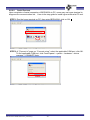
STEP1: Run the hyper-terminal on PC, then enter BEGA220A, click on OK.
STEP2: A “”Connect to” pops up, “Connect using”, select the applicable COM port, click OK.
To find applicable COM port, click Control panel – system – hardware – device
manager – COM&LPT ports.
BEGA220A USER MANUAL preliminary
- 26 -
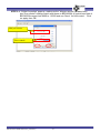
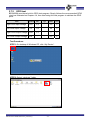
STEP3: A “COMx Properties” pops up, make sure the “bits per second” (or baud rate)
and ”flow control” settings match with those on BEGA220A. A typical baud rate of
BEGA220A ranges from 9600 to 115200 and use “None” for flow control. Click
on apply, then OK.
Bits per second
Flow control
BEGA220A USER MANUAL preliminary
- 27 -
BETA903A set up:
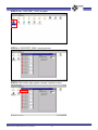
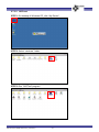
STEP1: After booting up BEGA220A, on Windows CE desktop, click on “My Device”.
STEP2: Select “Windows” folder.
STEP3: Run “SerialPortTest” program.
BEGA220A USER MANUAL preliminary
- 28 -
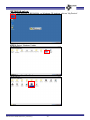
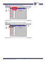
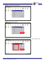
STEP4: A “SerialPortTest” running screen.
STEP5: Please make sure the baud rate setting on PC and BEGA220A are identical with a
typical range of 9600 to 115200, then click on “Open Port” to connect to PC.
Serial port select
BaudRate select
Open port
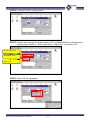
STEP6: Press “OK” as highlighted.
BEGA220A USER MANUAL preliminary
- 29 -
STEP7: Enter some trial text message on the “TX” box, then click on “Send Tx”.
STEP8:If everything goes on fine, user will see a receiving message as the one transmitted.
STEP9: Enter text at PC end, those test will be echoed in “Rx” box at BEGA220A.
BEGA220A USER MANUAL preliminary
- 30 -
2.6.3 Device USB setting up
BEGA220A provides one of Device USB to connect with PC and use software of ActiveSync.
As shown on below chart, and connect to USB.
Table of Device USB Pin assignment
USB
BEGA220A
Pin No Pin Name Pin No Pin Name
1
VBUS
10
VBUS
2
3
DD+
26
6
USBDN
USBDP
4
GND
30
GND
BEGA220A USER MANUAL preliminary
- 31 -
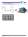
2.6.4 Speaker setting up
BEGA220A provides two sets of Speaker of 8Ω/2W. As shown on below chart, and connect
to Speaker.
1st set Speaker
Table of 1st set Speaker Pin assignment
Speaker
BEGA220A
Pin No Pin Name Pin No Pin Name
1
+
3
DSPC1
2
-
23
DSPC2
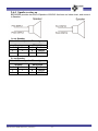
2nd set Speaker
Table of 2nd set Speaker Pin assignment
Speaker
BEGA220A
Pin No Pin Name Pin No Pin Name
1
+
4
DSPC3
2
-
24
BEGA220A USER MANUAL preliminary
DSPC4
- 32 -
2.7 ADC_GPIO Bus
2.7.1
Table of ADC_GPIO Bus Pin assignment
BEGA220A USER MANUAL preliminary
- 33 -
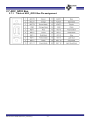
2.7.2
GPIO test
BEGA220A provides a build-in GPIO test program. Simply follows the recommended GPIO
circuit as illustrated on Chapter 4.4, then start using this test program to validate the GPIO
ports.
Item
Symbol
Min
Typ
Max
Unit
High Level Input Voltage
VIH
2.3
—
3.6
V
Low Level Input Voltage
VIL
-0.3
—
09
V
High Level Output Voltage VOH
3.1
—
3.3
V
Low Level Output Voltage
—
—
0.2
V
VOL
Test Procedure:
STEP1: On desktop of Windows CE, click “My Device”.
STEP2: Select “windows” folder.
BEGA220A USER MANUAL preliminary
- 34 -
STEP3: Run “GPIOTEST_220A” program.
STEP4: A “GPIOTEST_220A” running screen.
STEP5: PIN1 will be high (green colored) if switch is short.
BEGA220A USER MANUAL preliminary
- 35 -
STEP6: Choose “output” when test “Output”.
STEP7: The level at high when “KEY” be checked
BEGA220A USER MANUAL preliminary
- 36 -
2.7.3
ADC test
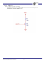
2.7.3.1 ADC connection of testing
As shown on below chart, connect ADC test circuit and use internal power of
BEGA220A. The max. voltage is 1.6V.
BEGA220A USER MANUAL preliminary
- 37 -
2.7.3.2 ADC test
STEP1: On desktop of Windows CE, click “My Device”.
STEP2: Select “windows” folder.
STEP3: Run ”ADCTest” program.
BEGA220A USER MANUAL preliminary
- 38 -
STEP4: A “ADCTest” running screen.
STEP5: Click “Start” for testing.
STEP6: Adjust VR that correspondent Prot will be changed. Click “Stop” to stop the test.
BEGA220A USER MANUAL preliminary
- 39 -
Chapter 3 BEGA220A Programming Guide
摘要
這章節提供 BEGA220A 如何和 PC 連線,和如何使用
軟體控制 Serial Port,GPIO,ADC,Backlight,SPI。
包含部份:
3.1 Transfer File Between BEGA220A and PC
3.2 Programming for BEGA220A
3.3 Serial Port Function
3.4 GPIO Control
3.5 A/D Converter and Backlight Adjustment
BEGA220A USER MANUAL preliminary
- 40 -
3.1 Transfer File Between BEGA220A and PC
3.1.1 Connect PC and BEGA220A
User could setup the connection between desktop PC and BEGA220A by following steps:
STEP 1. Install Microsoft ActiveSync 4.5 on desktop PC. The installation file of ActiveSync could
be downloaded at
http://www.microsoft.com/downloads/details.aspx?familyid=9e641c34-6f7f-404d-a04b-dc
09f8141141&displaylang=en&tm
After installation, you need to restart PC.
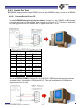
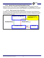
STEP 2. Connect desktop PC and BEGA220A by USB cable. Below picture shows the hardware
connection between desktop PC and BEGA220A for file transfer.
Host USB used for USB 1.0 device,
such as mouse, keyboard or USB
storage device.
BEGA220A
40 pin external bus
USB cable
Please note that the USB cable should plug into the connector of device USB wiring from
the 40 pin
external bus. Below table shows the pin assignment of device USB on the 40 pin external bus.
USB connector
40 pin external bus of BEGA220A
Pin No
Pin Name
Pin No
Pin Name
1
VBUS
10
VBUS
2
D-
26
USBDN
3
D+
6
USBDP
4
GND
30
GND
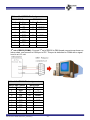
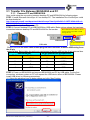
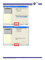
STEP 3. Power on BEGA220A and connect BEGA220A and PC by USB cable. For the first
connection, windows system on PC will request the USB device driver of BEGA220A. Please
install USB driver by following procedures.
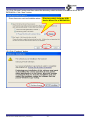
(1). Select the advance item on below dialog and click “Next” button.
BEGA220A USER MANUAL preliminary
- 41 -
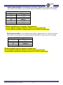
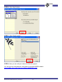
(2). Click “Browse” button and then select the directory which includes USB device driver file of
BEGA220A. Click “Next” button.
Directory which includes USB
device driver file of BEGA220A
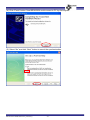
(3). Click “Continue” button
BEGA220A USER MANUAL preliminary
- 42 -
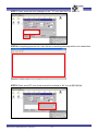
(4). Click “Finish” button. Now BEGA220A could connect to PC by ActiveSync.
(5). Select “No” and click “Next” button to cancel the synchronization.
BEGA220A USER MANUAL preliminary
- 43 -
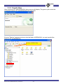
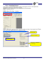
3.1.2 Transfer Files
After connecting PC and BEGA220A, below screen will display. The green cycle means the
connection between PC and BEGA220A has been built.
Execute ”Explore” program and move into the folder of BEGA220A, you can transfer files
between PC and BEGA220A
Folder of BEGA220A
BEGA220A USER MANUAL preliminary
- 44 -
3.2 Programming for BEGA220A
3.2.1 Setup Development environment
By following steps, we can setup the development environment for WinCE 5.0:
1. Install Microsoft eMbedded Visuall C++ 4.0(eVC 4.0) into desktop PC : eVC 4.0 can be
downloaded from
http://www.microsoft.com/downloads/details.aspx?FamilyID=1DACDB3D-50D1-41B2A107-FA75AE960856&displayLang=en.
2. Connect BEGA220A and Desktop PC by procedures in section 3.1.2
3. Install SDK of BEGA220A provided by Bolymin. The installation file could be found in the
product CD.
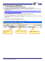
4. The platform setting of embedded Visual C++:
Following pictures show the necessary setting of eVC 4.0::
Select SMDK2416
platform
BEGA220A USER MANUAL preliminary
Debug or release version
- 45 -
SMDK2416 device
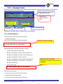
3.2.2 Create New Project
In this section, we will describe how to create a new project in eVC 4.0. An experienced
programmer could jump to next section directly.
You could create a new project for your application by following steps:
STEP 1: Execute eVC 4.0.
STEP 2: Select “File”-“New…: function
STEP 3: Select your application type, setup the location and name of your project and. Please
select “WCE MFC AppWizard(exe)” as application type.
Project name
Project location
Application type
Only select “ARMV4I”
as CPU type
BEGA220A USER MANUAL preliminary
- 46 -
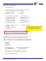
STEP 4: Select “Dialog based” and language setting. Click “Next” button.
STEP 5: Click “Next” button.
BEGA220A USER MANUAL preliminary
- 47 -
STEP 6: Click “Next” button.
STEP 7: Click “Finish” button.
STEP 8: Now you can add your codes into this new project.
You can get more development information from below MSDN website.
http://msdn.microsoft.com/en-us/library/bb847963.aspx
BEGA220A USER MANUAL preliminary
- 48 -
3.3 Serial Port Function
3.3.1 Overview
There are 4 serial ports in BEGA220A. Below table lists the function of each serial port:
Name
COM1:
COM3:
COM4:
Debug port
Function
RS422 or RS485 port
Used by application program.
Used by application program.
Internal used.
BEGA220A USER MANUAL preliminary
Comment
Option
2 wire RS232
2 wire RS232
Could not open by application program.
- 49 -
3.3.2 Serial Port Control-CSerialPort class
Bolymin provided a class, CSerialPort, which implements basic control logic for serial port.
Application could use this class by adding “CSerialPort.cpp” and “CSerialPort .h” into project.
Customer could modify the source code of class CSerialPort to expand the serial port functions.
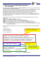
3.3.2.1 Basic concept of class CSerialPort
The object of class CSerialPort will handle all data transfer and receive of opened serial port.
Once there is any data is received by the opened serial port, CSerialPort object will send a user
defined message to user defined window which should be main window of application program.
Below picture shows the flow:
Window of user application
Call Send() function to
send data by serial port
User application should
catch this message to get
received data
Send user defined
message to user window
Received
data
CSerialPort object
BEGA220A USER MANUAL preliminary
- 50 -
Serial port
3.3.2.2
Member function of class CSerialPort
CSerialPort Function: Constructor function of calss CSerialPort.
CSerialPort(
Syntax
);
None
Parameters
Return value None
Open Function: Open a serial port.
BOOL Open(
Syntax
LPCTSTR
port,
int
baud_rate,
int
data_bit
int
stop_bit
int
parity
);
port
Name of serial port listed in the table of section 3.3.1.
Parameters
baud_rate Baud rate, ex: 9600.
data_bit
Data_bit, 7 ~ 8
stop_bit
Stop bit , ONESTOPBIT, ONE5STOPBITS or TWOSTOPBITS.
parity
Parity , NOPARITY, ODDPARITY, EVENPARITY.
Return value TRUE: Open serial port successfully
FALSE: .Open serial port fail.
Send Function: Send specified data by this serial port.
BOOL Send(
Syntax
LPCVOID buf_ptr,
DWORD data_len
);
buf_ptr
Memory pointer of data will be sent.
Parameters
data_len
Length of data will be sent. (UNIT: byte)
Return value TRUE: Send data successful.
FALSE: Send data fail.
SetCommMsg Function: CSerialPort object will send a receive message to specified window.
User need to call this function to set the receive message value and the window that will receive
message.
void SetCommMsg(
Syntax
HWND win_handle,
UINT receive_msg
);
win_handle
Handle of the window that will receive message.
Parameters
receive_msg
User defined message value.
Return value None
Close Function: Close current serial port.
BOOL Close (
Syntax
);
None
Parameters
Return value TRUE: Close serial port successfully.
FALSE: Cloas serial port fail.
BEGA220A USER MANUAL preliminary
- 51 -
3.3.2.3
How to catch the receive message
Please follow below steps to catch the receive message.
STEP 1: Define a receive message in your code as below:
const UINT WM_CMD_OK = WM_USER+1;
STEP 2: Declare a message processing function in the window that will process receive
message.
STEP 3: Create message mapping.
STEP 4: Implement the receive message processing function.
BEGA220A USER MANUAL preliminary
- 52 -
3.3.3 Example Code
Bolymin provide a test application and its source code for example. Below picture is the screen
shot of the serial port test program:
Select serial port and setup
its parameter values.
Open/Close
selected serial
port.
Data will be sent by
selected serial port
Send data
Received data
Clear sent data.
Clear received data
Below are the major source codes of the test program:
File: SerialPortDlg.cpp
/////////////////////////////////////////////////////////////////////////////
// CSerialPortDlg dialog
/////////////////////////////////////////////////////////////////////////////
Define a receive message
const UINT WM_CMD_OK = WM_USER+1;
BEGIN_MESSAGE_MAP(CSerialPortDlg, CDialog)
//{{AFX_MSG_MAP(CSerialPortDlg)
ON_BN_CLICKED(IDC_OPEN_COM, OnOpenCom)
ON_BN_CLICKED(IDC_CLOSE_COM, OnCloseCom)
ON_BN_CLICKED(IDC_SEND, OnSend)
ON_BN_CLICKED(IDC_CLEAR_SEND, OnClearSend)
ON_BN_CLICKED(IDC_CLEAR_REC, OnClearRec)
ON_WM_DESTROY()
//}}AFX_MSG_MAP
ON_MESSAGE(WM_CMD_OK, OnCommRecv)
END_MESSAGE_MAP()
/////////////////////////////////////////////////////////////////////////////
// CSerialPortDlg message handlers
/////////////////////////////////////////////////////////////////////////////
BEGA220A USER MANUAL preliminary
- 53 -
Map the receive message
processing function to user defined
message.
BOOL CSerialPortDlg::OnInitDialog()
{
CDialog::OnInitDialog();
// Set the icon for this dialog. The framework does this automatically
// when the application's main window is not a dialog
SetIcon(m_hIcon, TRUE);
// Set big icon
SetIcon(m_hIcon, FALSE);
// Set small icon
CenterWindow(GetDesktopWindow());
// center to the hpc screen
m_ComboBaud.SetCurSel(5);
/* Define BaudRate: 115200 */
m_ComboData.SetCurSel(1);
/* Define data bit: 8 bit */
m_ComboParity.SetCurSel(0);
/* Define parity: none */
m_ComboPort.SetCurSel(0);
/* Define searial port: COM1 */
m_ComboStop.SetCurSel(0);
/* Define stop bit: 1bit */
m_ButClose.EnableWindow(FALSE);
/* "Close"Button is disable*/
m_strRecDisp = _T("");
Create a CSerialPort object and set
current window as the window
which will process received data.
m_cSendBuffer = new char[60];
UpdateData(FALSE);
m_pSerialPort = new CSerialPort();
m_pSerialPort->SetCommMsg(m_hWnd, WM_CMD_OK);
return TRUE;
}
/*******************************************************************************************
Implement function used to process receive data from serial port
********************************************************************************************/
LRESULT CSerialPortDlg::OnCommRecv(WPARAM wParam, LPARAM lParam)
{
CString tmp;
char *buf;
DWORD buflen;
buf = (char *)wParam;
// memory pointer of received data
buflen = (DWORD)lParam;
// received data length
CEdit *pRecvStrEdit = (CEdit*)GetDlgItem(IDC_REC_DISP);
for (int i = 0; i < buflen; i++, buf++)
BEGA220A USER MANUAL preliminary
- 54 -
{
tmp.Format(_T("%c"), *buf);
m_strRecDisp += tmp;
}
pRecvStrEdit->SetWindowText(m_strRecDisp);
/* Show */
return 0;
}
// Initial user interface
const CString PorTbl[4] = {_T("COM1:"),_T("COM3:"),_T("COM4:"),_T("COM6:")};
const DWORD BaudTbl[6] = {4800, 9600, 19200, 38400, 57600,115200};
const DWORD DataBitTbl[2] = {7, 8};
const BYTE StopBitTbl[3] = {ONESTOPBIT, ONE5STOPBITS, TWOSTOPBITS};
const BYTE ParityTbl[4] = {NOPARITY, ODDPARITY, EVENPARITY, MARKPARITY};
/*******************************************************************************************
Function for “OPEN” button used to open selected serial port.
********************************************************************************************/
void CSerialPortDlg::OnOpenCom()
{
UpdateData(TRUE);
CString strPort = PorTbl[m_ComboPort.GetCurSel()];
DWORD baud = BaudTbl[m_ComboBaud.GetCurSel()];
Open selected serial port
by specified parameter
values.
DWORD databit = DataBitTbl[m_ComboData.GetCurSel()];
BYTE stopbit
= StopBitTbl[m_ComboStop.GetCurSel()];
BYTE parity
= ParityTbl[m_ComboParity.GetCurSel()];
BOOL ret = m_pSerialPort->Open(strPort, baud, databit, stopbit, parity);
if (ret == FALSE)
{
MessageBox(_T("Open ") + strPort + _T(" Fail!"));
return;
}
m_ButOpen.EnableWindow(FALSE);
/* Disable "open" button */
m_ButClose.EnableWindow(TRUE);
/* Enable "close" button */
MessageBox(_T("Open ") + strPort + _T(" is OK!"));
}
BEGA220A USER MANUAL preliminary
- 55 -
/*******************************************************************************************
Function for “CLOSE” button used to close current serial port.
********************************************************************************************/
void CSerialPortDlg::OnCloseCom()
{
Close current serial
port.
m_pSerialPort->Close();
m_ButOpen.EnableWindow(TRUE);
/* Enable "Open" button */
m_ButClose.EnableWindow(FALSE);
/* Disable "close" button */
}
/*******************************************************************************************
Function for “SEND” button used to send data by serial port.
********************************************************************************************/
void CSerialPortDlg::OnSend()
{
UpdateData(TRUE);
int len = m_strSendEdit.GetLength();
Send data by current serial
port.
for(int i = 0; i < len;i++)
m_cSendBuffer[i] = (char)m_strSendEdit.GetAt(i);;
BOOL status = m_pSerialPort->Send(m_cSendBuffer, len);
if (!status)
MessageBox(_T("Can't write string to COM"),_T("Error"),MB_OK);
}
/*******************************************************************************************
Destory function of serial port test dialog
********************************************************************************************/
void CSerialPortDlg::OnDestroy()
{
CDialog::OnDestroy();
m_pSerialPort->Close();
delete m_pSerialPort;
Close current serial port
and delete CSerialPort
object.
delete m_cSendBuffer;
}
BEGA220A USER MANUAL preliminary
- 56 -
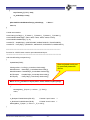
3.4 GPIO Control
3.4.1 How to Control GPIO for BEGA220A
Bolymin provides a DLL file “pGPIO_220A.dll” to control the General Purpose Input and
Ouput(GPIO) signal. In BEGA220A, there are 12 user defined GPIO. User could read current
value of all GPIO of BEGA220A, change values of GP output signal and set the attribute of GPIO
by functions in “pGPIO_220A.dll”.
User could use GPIO control functions by following procedures:
STEP 1. Add “pGPIO_220A.h” into project.
STEP 2. Load “pGPIO_220A.dll” by “Loadlibrary()” function.
STEP 3. Get the address of control functions by “GetProcAddress()” function.
STEP 4. Execute GPIO control functions by the address got at STEP3.
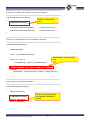
Below is a simple example code to use the GPIO control functions:
// variable declaration
HINSTANCE m_hModule;
BOOL (*m_pGetGPInput)(int);
void (*m_pSetGPOutput)(int, BOOL);
Load “pGPIO_220A.dll” and get the
address of GPIO control functions.
BOOL (*m_pIsOutput)(int);
void (*m_pSetIOAttribute)(int, BOOL);
m_hModule=::LoadLibrary(_T("pGPIO_220A.dll"));
m_pGetGPInput = (BOOL (*)(int))::GetProcAddress(m_hModule,_T("GetGPInput"));
m_pSetGPOutput = (void (*)(int, BOOL))::GetProcAddress(m_hModule,_T("SetGPOutput"));
m_pIsOutput = (BOOL (*)(int))::GetProcAddress(m_hModule,_T("IsOutput"));
m_pSetIOAttribute = (void (*)(int, BOOL))::GetProcAddress(m_hModule,_T("SetIOAttribute"));
m_pSetIOAttribute(GIO_KEY1, GA_INPUT);
m_bPOUT1 = m_pGetGPInput(GIO_KEY1);
m_pSetIOAttribute(GIO_KEY1, GA_OUTPUT);
Execute GPIO control functions.
if (m_pIsOutput(GIO_KEY1))
m_pSetGPOutput(GIO_KEY1, TRUE);
BEGA220A USER MANUAL preliminary
- 57 -
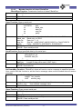
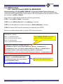
3.4.2 GPIO Control Function for BEGA220A
GetGPInput Function: Get current status of specified GPIO.
BOOL GetGPInput (
Syntax
int gpio_index
);
gpio_index
The index of specified GPIO. Refer to section 3.4.3 for
Parameters
the value definition.
Return value TRUE: Current status of specified GPIO is HIGH.
FALSE: Current status of specified GPIO is LOW.
SetGPOutput Function: Set value of specified GP Output.
void SetGPOutput (
Syntax
int gpio_index,
BOOL value
);
gpio_index
The index of specified GP output. Refer to section 3.4.3
Parameters
for the value definition.
value
New value of specified GP output.
TRUE: Set specified GP output to HIGH.
FALSE: Set specified GP output to LOW.
Return value None
IsOutput Function: Check if the specified GPIO is output or not..
BOOL IsOutput (
Syntax
int gpio_index
);
gpio_index
The index of specified GPIO. Refer to section 3.4.3 for
Parameters
the value definition.
Return value TRUE: The specified GPIO is output.
FALSE: The specified GPIO is input.
SetIOAttribute Function: Set the attribute of the specified GPIO.
void SetIOAttribute (
Syntax
int gpio_index,
BOOL value
);
gpio_index
The index of specified GPIO. GIO_KEY1~GIO_KEY12.
Parameters
value
New attribute of the specified GPIO.
GA_OUTPUT: Set the specified GPIO as output.
GA_INPUT: Set the specified GPIO as input.
Return value None
BEGA220A USER MANUAL preliminary
- 58 -
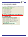
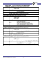
3.4.3 Definition of GPIO Index
Class CGPIO_220A support following index values:
GPIO index
Description
GIO_KEY1
User defined general purpose input/output. (KEY1)
GIO_KEY2
User defined general purpose input/output. (KEY2)
GIO_KEY3
User defined general purpose input/output. (KEY3)
GIO_KEY4
User defined general purpose input/output. (KEY4)
GIO_KEY5
User defined general purpose input/output. (KEY5)
GIO_KEY6
User defined general purpose input/output. (KEY6)
GIO_KEY7
User defined general purpose input/output. (KEY7)
GIO_KEY8
User defined general purpose input/output. (KEY8)
GIO_KEY9
User defined general purpose input/output. (KEY9)
GIO_KEY10
User defined general purpose input/output. (KEY10)
GIO_KEY11
User defined general purpose input/output. (KEY11)
GIO_KEY12
User defined general purpose input/output. (KEY12)
GO_BLIGHT_ENABLE
Backlight control. Default value : HIGH.
GO_LCD_POWER_ENABLE LCD power control. Default value : LOW.
GO_AMP_SWITCH
Amplifier switch. Default vale: LOW.
GO_EN485
Reserved for internal use.
BEGA220A USER MANUAL preliminary
- 59 -
3.5 ADC Converter and Backlight Adjustment
3.5.1 Overview
Bolymin provides a dynamic link library “CtrlFunc_220A.dll” which includes all control functions
of A/D converter and backlight adjustment.
For A/D converter, there are 6-ch A/D converters with 12-bit resolution in BEGA220A. User could
read the value from selected A/D converter channel by functions provided by Bolymin.
Suggested hardware wiring about A/D converter could be found in user manual. Detail
description of control functions of A/D converter could be found in section 3.5.2.
For backlight adjustment, user could get current brightness value or change the brightness of
backlight by control functions. The description of control functions of backlight adjustment could
be found in section 3.5.3.
User could use control functions about A/D converter and backlight adjustment by following
procedures:
STEP 1. Add “CtrlFunc_220A.h” into project.
STEP 2. Load “CtrlFunc_220A.dll” by “Loadlibrary()” function.
STEP 3. Get the address of control functions by “GetProcAddress()” function.
STEP 4. Execute control functions about A/D converter by the address got at STEP3.
STEP 5. Call “FreeLibrary()” function to free the reference of “CtrlFunc_220A.dll” while ending
the application program.
Below is a simple example code to use the control functions about A/D converter and backlight
adjustment:
// variable declaration
Load “CtrlFunc_220A.dll” and get
the address of control functions.
HINSTANCE m_hModule;
BOOL (*m_pInitADC)(void);
int (*m_pReadADC)(int);
m_hModule=::LoadLibrary(_T("CtrlFunc_220A.dll"));
m_pInitADC = (BOOL (*)(void))::GetProcAddress(m_hModule,_T("InitADC"));
m_pReadADC = (int (*)(int))::GetProcAddress(m_hModule,_T("ReadADC"));
m_pInitBacklightCtrl = (BOOL (*)(void))::GetProcAddress(m_hModule,_T("InitBacklightCtrl"));
m_pGetBrightness = (int (*)(void))::GetProcAddress(m_hModule,_T("GetBrightness"));
m_pSetBrightness = (int (*)(int))::GetProcAddress(m_hModule,_T("SetBrightness"));
Execute control functions of
A/D converter.
m_pInitADC();
value = m_pReadADC(ADC_CHANNEL0);
m_pInitBacklightCtrl();
Execute control functions
of backlight adjustment.
brightness = m_pGetBrightness();
m_pSetBrightness(brightness+5); // Increase the brightness by 5
m_pSetBrightness(0);
// OFF the backlight
FreeLibrary(m_hModule);
// free the reference of “CtrlFunc_220A.dll”
BEGA220A USER MANUAL preliminary
- 60 -
3.5.2 Control Function of A/D Converter
nitADC Function: A/D converter initialization. User need to call this function before
using A/D converter.
BOOL initADC (
Syntax
);
None
Parameters
Return value TRUE: Initial A/D converter successfully.
FALSE: Fail to initial A/D converter.
ReadADC Function: Read A/D converted data from specified A/D converter channel.
Int ReadADC(
Syntax
int adc_channel
);
adc_channel
The index of specified A/D converter channel.
Parameters
ADC_CHANNEL0~ADC_CHANNEL5
Return value A/D converted data from specified A/D converter channel.
BEGA220A USER MANUAL preliminary
- 61 -
3.5.3 Function about Backlight Adjustment
InitBacklightCtrl Function: Initial backlight controller. User need to call this function before
adjusting backlight brightness.
BOOL InitBacklightCtrl (
Syntax
);
None
Parameters
Return value TRUE: Initial backlight controller successfully.
FALSE: Fail to initial backlight controller.
GetBrightness Function: Get current brightness value of backlight.
int GetBrightness (
Syntax
);
None
Parameters
Return value Current brightness value of backlight. (0~100)
SetBrightness Function: Set brightness value of backlight.
Int SetBrightness(
Syntax
int new_value
);
new_value
New brightness value of backlight. (0~100)
Parameters
0: Turn OFF the backlight
Return value Original brightness value of backlight.
BEGA220A USER MANUAL preliminary
- 62 -