1
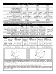
Owners Manual MSS650 Loudspeaker System MSS650 McIntosh Laboratory, Inc. 2 Chambers Street Binghamton, New York 13903-2699 Phone: 607-723-3512 FAX: 607-724-0549 Thank You Table of Contents Your decision to own this McIntosh MSS650 Loudspeaker System ranks you at the very top among discriminating music listeners. You now have The Best. The McIntosh dedication to Quality, is assurance that you will receive many years of musical enjoyment from this unit. Please take a short time to read the information in this manual. We want you to be as familiar as possible with all the features and functions of your new McIntosh. Thank You .......................................................................... 2 Please Take a Moment ....................................................... 2 Technical Assistance .......................................................... 2 Customer Service ............................................................... 2 Table of Contents ............................................................... 2 Safety Instructions ............................................................. 3 Introduction ....................................................................... 4 Performance Features ........................................................ 4 Overall Dimensions ........................................................... 4 Installation ......................................................................... 6 How to Connect a Two Way System ................................. 8 How to Connect a Bi-Amp Three Way System ................. 9 Specifications .................................................................. 10 Packing Instructions ........................................................ 11 Please Take A Moment The serial number, purchase date and McIntosh dealer name are important to you for possible insurance claim or future service. The spaces below have been provided for you to record that information: Serial Number: Purchase Date: Dealer Name: Technical Assistance If at any time you have questions about your McIntosh product, contact your McIntosh dealer who is familiar with your McIntosh equipment and any other brands that may be part of your system. If you or your dealer wish additional help concerning a suspected problem, you can receive technical assistance for all McIntosh products at: McIntosh Laboratory, Inc. 2 Chambers Street Binghamton, New York 13903 Phone: 607-723-3512 Fax: 607-723-3636 Customer Service If it is determined that your McIntosh product is in need of repair, you can return it to your dealer. You can also return it to the McIntosh Laboratory Service Repair Department. For assistance on factory repair return procedure, contact the McIntosh Repair Department at: McIntosh Laboratory, Inc. 2 Chambers Street Binghamton, New York 13903 Phone: 607-723-3515 Fax: 607-723-1917 Copyright 2000 ã by McIntosh Laboratory, Inc. 2 General Notes 1. A McIntosh MSS650 Loudspeaker System consists of a pair of MS650 Woofer/Midranges, a pair of MS10 Tweeters and a pair of MN650 Crossover Networks. 2. Do not exceed the power handling capacity of the MSS650 Loudspeaker System. 3. For additional connection information, refer to the owners manual(s) for any component(s) connected to the MSS650 Loudspeaker Drivers and Crossover Networks. 4. The Two and Three Way Speaker System Connection Illustrations in this Owners Manual are only two examples of the many different possible combinations. It is recommended that a qualified professional assist you in the choice and installation of a McIntosh Sound System for your vehicle. Safety Instructions IMPORTANT SAFETY INSTRUCTIONS! PLEASE READ THEM BEFORE OPERATING THIS EQUIPMENT. General: 1. Read all the safety and operating instructions, contained in this owners manual, before operating this equipment. 2. Retain this owners manual for future reference about safety and operating instructions. 3. Adhere to all warnings and operating instructions. 4. Follow all operating and use instructions. 5. Warning: To reduce risk of fire or electrical shock, do not expose this equipment to rain or moisture. This unit is capable of producing high sound pressure levels. Continued exposure to high sound pressure levels can cause permanent hearing impairment or loss. User caution is advised and ear protection is recommended when playing at high volumes. Installation: 6. Do not attempt to install the unit yourself. Please have an authorized dealer install the unit for you. 7. Locate the equipment away from heat sources such as heater ducts. 8. Mount the equipment only as described in this owners manual. Repair of Equipment: 13. Refer servicing to a qualified service personnel under the following conditions: A. The cords or the connectors have been damaged. B. Objects have fallen onto, or liquid has been spilled into the equipment. C. The equipment has been exposed to rain or water. D. The equipment does not operate normally by following the operating instructions contained within this owners manual. E. The equipment has been dropped or damaged in any way. F. The equipment exhibits a distinct change in performance - this indicates a need for service. 14. When replacement parts are required, be sure the service technician has used replacement parts specified by McIntosh or have the same characteristics as the original part. Unauthorized substitutions may result in fire, electric shock, or other hazards. 15. Upon completion of any service or repairs to this product, ask the service technician to perform safety checks to determine that the product is in proper operating condition. Connection: 9. Connect this equipment only to the type of power amplifier as described in this owners manual. 10. Route cords so that they are not likely to be pinched by items placed upon or against them, paying particular attention to the point where they exit from the instrument. Care of Equipment: 11. Clean the instrument by dusting with a dry cloth. 12. Do not permit objects of any kind to be pushed into and/or fall into the equipment through enclosure openings. Never spill liquids into the equipment through enclosure openings. 3 Introduction The McIntosh woofer/midrange and tweeter drivers offer extremely smooth frequency response, low distortion, high sensitivity and high power handling capability. When these drivers are combined with other McIntosh Automotive components, you will enjoy sonically accurate music reproduction in your vehicle which meets McIntosh traditional standards of excellence. Side View of the MS10 Tweeter Driver with Angle Mounting Bracket Performance Features · Patented Technology The widely acclaimed McIntosh LD/HP® (Low Distortion/ High Performance) Magnetic Circuit Design1 dramatically reduces harmonic distortion. · Die Cast Aluminum Frames Die cast aluminum frames ensure excellent rigidity, dimensional integrity and lasting value. · Fifteen Ounce Strontium Ferrite Magnet The Strontium V Magnet ensures high loudspeaker efficiency, a high heat tolerance and reliable operation at high power levels. Side View of the MS10 Tweeter Driver with Flush Mounting Bracket · Low Distortion Crossover The crossover utilizes Polypropylene capacitors and low distortion Drum inductors. Options include a 6dB tweeter attenuator and Bi-Amp capability. · Eleven Gram Neodymium Magnet The Tweeter Magnet has the highest flux energy that is currently available. · Specially Treated Fabric Dome The Tweeter Dome Material is constructed from a treated fabric which offers excellent internal damping with structural rigidity. · Magnetic Fluid Cooling Fluid suspended in the Tweeter Voice Coil Gap helps to reduce volume compression and smooth the response. 1 4 Patent Number 5,151,943 Side View of the MS10 Tweeter Driver with Surface Mounting Bracket Introduction, Performance Features and Overall Dimensions Front View of the MS650 Woofer/Midrange Driver Side View of the MN650 Crossover Network Top View of the MN650 Crossover Network Side View of the MS650 Woofer/Midrange Driver 5 Installation It is recommended that a qualified professional install all McIntosh Automotive Products. McIntosh Woofer/ Midrange Drivers, Tweeters and Crossover Networks should be used in conjunction with McIntosh Subwoofers and McIntosh Automotive electronics to achieve the best possible performance. McIntosh Subwoofers are designed to operate in the bass frequency range below 120Hz and need not be physically close to midrange and tweeter speakers in order to maintain good imaging and system frequency balance. Mounting the Woofer/Midrange 1. Using the enclosed template as a guide, mark and drill the four pilot holes for the mounting screws. Drill the mounting holes with an appropriate size drill bit. 2. Cut out the marked circle in the template, and using it as a guide, mark and cutout the circular hole for the loudspeaker in the vehicle panel or suitable enclosure. 3. Slide four spring clips, with their flat sides facing the driver, onto the edge of the cutout and centered over each of the four mounting holes. Refer to figure 1. 4. Place the narrow Mounting foam ring gasket in Surface the matching groove of the plastic mounting ring. 5. Carefully lower the driver into the plastic mounting ring, with the foam ring Figure 1 side facing the driver and making sure the driver mounting holes are aligned with the matching holes in the mounting ring. 6 6. Place the wide foam ring gasket on the back side of the plastic mounting ring that will contact the vehicle panel or enclosure. 7. Carefully insert the driver/mounting ring assembly into the cutout. Secure the assembly by inserting four of the #8 x 1 inch supplied screws, through the driver holes, the plastic mounting ring holes and into the spring clip fasteners previously installed over the mounting holes. 8. Press the metal grille cover into the speaker mounting ring. Mounting the Crossover The crossovers are supplied with a removable cover that is hinged at the rear and is secured to the base at the front with two machine screws. When selecting a crossover mounting location, make sure that there is adequate room for the top to be raised and removed. 1. Remove the crossover cover machine screws, lift up and unhinge the cover. Refer to figure 2. 2. Using the base of the crossover as a template, mark the four locations to drill holes in the mounting surface for the Figure 2 crossover mounting screws. Drill four holes with an appropriate size drill bit. Refer to figure 3. 3.Secure the Mounting Screw Locations crossover to the mounting surface with the four #6 x 1 inch supplied screws. 4. Reinstall the crossover cover and secure it with the two machine screws. 5. Follow inFigure 3 structions for connecting the crossover to the loudspeakers. Installation Mounting the Tweeter Dual Angle Bracket Two different tweeter mounting angles are possible with the bracket supplied. Choose the one which best fits the vehicle. Refer to figures 4 and 6. 1. Drill holes with an appropriate size drill bit in the mounting surface for the two tweeter wires and the two bracket mounting screws. Also drill corresponding holes in the mounting surface. 2. Secure the bracket with two of the screws supplied. 3. Install the wires to the tweeters by pressing the push-on connectors onto the tweeter connecting lugs. Observe polarity with Red cables to the Positive (+) lugs and Black cables to the negative (-) lugs. 4. Carefully bend the push-on connectors inward to allow the wiring to fit in the bracket. Do not bend the tweeter connecting lugs. Refer to figure 5. 5. Align the tweeter with the bracket and snap in place. Mounting the Tweeter Surface Bracket 1. Drill holes in the mounting surface with an appropriate size drill bit for the two tweeter wires and the two bracket mounting screws using the round and rectangular holes in the mounting bracket as a guide. Refer to figure 7. 2. Secure the bracket with two of the supplied mounting screws. 3. Feed the tweeter wires from behind the mounting panel, through the mounting bracket, and install to the tweeter by pressing the push-on connectors onto the tweeter connecting lugs. Observe polarity with the red wire connected to the positive (+) lug and the black wire connected to the negative (-) lug. 4. Align the tweeter with the bracket and snap in place. Dual Angle Mounting Bracket inside view Figure 4 Drill bit guides for hookup cable and mounting screws Tweeter Bent push on connector Tweeter Lug Figure 5 Dual Angle Mounting Mounting Bracket Surface 123456789012345678901234567890121234567890123456789 123456789012345678901234567890121234567890123456789 123456789012345678901234567890121234567890123456789 123456789012345678901234567890121234567890123456789 Figure 6 Tweeter Surface Mounting Bracket Mounting Surface Tweeter Lugs 123456789012345678901234567890121234567890123456789 123456789012345678901234567890121234567890123456789 123456789012345678901234567890121234567890123456789 123456789012345678901234567890121234567890123456789 Figure 7 Mounting the Tweeter Flush Bracket 1. Cut a hole, using the supplied template. Insert the flush mounting spring clips into the slots in the cup and thread the supplied screw into the inside center of the mounting cup. Insert the cup into the hole and tighten the screw until the spring clips are secured. Refer to figure 8. 2. Snap the tweeter into the surface mounting bracket. 3. Feed the tweeter wires from behind the mounting panel, through the cup, and install to the tweeter by pressing the push-on connectors onto the tweeter connecting lugs. Observe polarity with the red wire connected to the positive (+) lug and the black wire connected to the negative (-) lug. 4.Insert the assembly into the cup and rotate clockwise until it locks in position. Tweeter Surface Mounting Bracket Tweeter Lugs Mounting Surface Flush Mount Cup 123456789012345678901234567890121234567890123456789 123456789012345678901234567890121234567890123456789 123456789012345678901234567890121234567890123456789 123456789012345678901234567890121234567890123456789 Spring Clips Figure 8 7 How to Connect a Two Way System How to Connect a Two Way System 1. Press the connector ends of the supplied Woofer/ Midrange Red/Black cables onto the matching Woofer/ Midrange connecting lugs. Connect the Tweeters in a similar manner. 2. Attach the tinned ends of the two Red/Black Woofer/ Midrange cables to the Crossover Network WOOFER OUTPUT terminals. The Black wire connects to a MINUS (-) terminal and the Red wire to a PLUS (+) terminal. 3. Attach the tinned ends of the two Red/Black Tweeter cables to the Crossover Network TWEETER terminals. The Black wire connects to a MINUS (-) terminal and the Red wire to a PLUS (+) terminal. 4. Connect the MINUS (-) OUTPUTS of a McIntosh Power Amplifier to the MINUS SINGLE AMP WOOFER INPUT Crossover Network terminals and the PLUS (+) OUTPUTS to the PLUS (+) SINGLE AMP TWEETER Crossover Network terminals. + Left Tweeter - Figure 9 + Right Tweeter Left Woofer/Midrange Left Crossover Network Right Woofer/Midrange Right Crossover Network McIntosh Stereo Power Amplifier 8 5. An optional modification to the Crossover Network produces a 6dB reduction in Tweeter level. When facing the ter- BiAmp Jumpers - 6 dB Jumper minal side of the crossover, cut the wire loop located on the right side of the crossover. Refer to figure 9. How to Connect a Bi-AmpThree Way System How to Connect a Bi-Amp Three Way System Configure the Crossover Networks for Bi-Amp operation by performing the following modification. When facing the terminal side of the Crossover Network, cut the two wire loops located on the left side. Refer to figure 9. 1. Press the connector ends of the supplied Woofer/ Midrange Red/Black cables onto the matching Woofer/ Midrange connecting lugs. Connect the Tweeters in a similar manner. 2. Attach the tinned ends of the two Red/Black Woofer/ Midrange cables to the Crossover Network WOOFER OUTPUT terminals. The Black wire connects to a MINUS (-) terminal and the Red wire to a PLUS (+) terminal. 3. Attach the tinned ends of the two Red/Black Tweeter cables to the Crossover Network TWEETER terminals. The Black wire connects to a MINUS (-) terminal and the Red wire to a PLUS (+) terminal. Left Tweeter + - 4. Connect cables from the Outputs of a McIntosh Six Channel Power Amplifier to the Crossover Networks, and to a pair of McIntosh Subwoofers as indicated in the drawing below. 5. An optional modification to the Crossover Network produces a 6dB reduction in Tweeter level. When facing the terminal side of the crossover, cut the wire loop located on the right side of the crossover. Refer to figure 9. + Right Tweeter Left Woofer/Midrange Right Woofer/Midrange Left Crossover Network Right Crossover Network - + + McIntosh Six Channel Power Amplifier McIntosh Subwoofer - McIntosh Subwoofer 9 Specifications MS650 Woofer/Midrange Specifications MSS650 General Specifications Frequency Response Reference Sensitivity (SPLo) Nominal Impedance (Znom) Free Air Resonance (Fo) Total Q (Qts) Equivalent Acoustic Volume (Vas) Voice Coil Resistance (Revc) Piston Area (Sd) Flux Density x Wire Length (BL) Impedance Maximum (Zmax) Reference Efficiency (ho) Mechanical Q (Qms) Electrical Q (Qes) Mechanical Compliance (Cms) Moving Mass + Air Load (Mms) Voice Coil Winding Height (Hvc) Power Handling (max) Continuous Power (EIA) System Sensitivity 80 Hz - 8kHz 89 dB 4 Ohms 47 Hz 0.46 23.5 Litr 3.3 Ohms 0.0127 sq m 4.7 TM 37 Ohms 0.5 % 5.2 0.5 1026 uM/N 11 grams 9.5 mm MS10 Tweeter Specifications Frequency Response Reference Sensitivity (SPLo) Nominal Impedance (Znom) 2.2 kHz - 20kHz 88.5 dB 6 Ohms MN650 Crossover Network Specifications Crossover Frequency Low Pass Slope High Pass Slope 2400 Hz 18 db/oct 18 db/oct Mounting Dimensions MS650 Woofer/Midrange Grille Overall (Diameter) Speaker + Grille Overall Depth Speaker Mounting Depth Speaker + Grille Mounting Depth Mounting Hole Diameter 7-5/8 (194mm) 3-15/16 (100mm) 3 (76mm) 2-3/4(69.8mm) 5-7/8(149mm) MS10 Tweeter Diameter Total Height 1-3/4 (45mm) 1-1/16 (267mm) MN650 Crossover Network Clearance Height 5 (127mm) 10 120 watts 60 watts 85 dB Note: The System Sensitivity includes the Woofer/Midrange Driver, Tweeter and Crossover Network Weight MS650 Net 2.5 MS10 Net 0.2 MN650 Net 1.7 MSS650 Net 8.8 MSS650 in Shipping Carton 12.4 lbs. lbs. lbs. lbs. lbs. (1.13 kg) (0.07 kg) (0.75 kg) (3.99 kg) (5.62 kg) Packing Instructions Packing Instructions In the event it is necessary to repack the equipment for shipment, the equipment must be packed exactly as shown below. Use the original shipping carton and interior parts only if they are all in good serviceable condition. If a shipping carton or any of the interior part(s) are needed, please call or write Customer Service Repair Department of McIntosh Laboratory. Please see the Parts List for the correct part numbers. Quantity 1 1 1 1 Part Number 034080 040608 040598 048273 1 1 052087 049271 1 2 052049 052092 Description Shipping Carton complete Woofer/Midrange Template Tweeter Template Woofer/Midrange Hardware Package Tweeter Hardware Package Crossover Network Hardware Package Cable Package Speaker Grille Kit MS650 MS10 MS650 MN650 11 McIntosh Laboratory, Inc. 2 Chambers Street Binghamton, NY 13903 McIntosh Part No. 040721