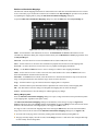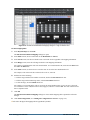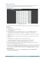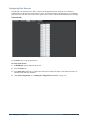
1
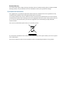
NK-VRC Virtual Routing Core User Guide NK-VRC Virtual Routing Core · User Guide • Ross Part Number: 9807DR-1009-03 • Release Date: March 25, 2013. Printed in Canada. The information contained in this guide is subject to change without notice or obligation. Copyright © 2013 Ross Video Limited. All rights reserved. This work is proprietary and confidential to Ross Video Limited, its subsidiaries and its other affiliated corporations and may not be copied, distributed, sold or otherwise used or relied upon without the express written permission of Ross Video Limited. Reproduction or reverse engineering of copyrighted software is prohibited. Patents This product is protected by the following US Patents: 4,205,346; 5,115,314; 5,280,346; 5,561,404; 7,034,886; 7,508,455; 7,602,446; 7,834,886; 7,914,332. This product is protected by the following Canadian Patents: 2039277; 1237518; 1127289. Other patents pending. Notice The material in this manual is furnished for informational use only. It is subject to change without notice and should not be construed as commitment by Ross Video Limited. Ross Video Limited assumes no responsibility or liability for errors or inaccuracies that may appear in this manual. Trademarks • is a registered trademark of Ross Video Limited. • Ross, ROSS, and ROSS®, are registered trademarks of Ross Video Limited. • Microsoft, MSN, and Windows are either registered trademarks or trademarks of Microsoft Corporation in the United States and/or other countries. • All other product names and any registered and unregistered trademarks mentioned in this guide are used for identification purposes only and remain the exclusive property of their respective owners. Important Regulatory and Safety Notices Before using this product and any associated equipment, refer to the Important Safety Instructions listed below so as to avoid personal injury and to prevent product damage. Products may require specific equipment, and/or installation procedures be carried out to satisfy certain regulatory compliance requirements. Notices have been included in this publication to call attention to these Specific requirements. Symbol Meanings The exclamation point within an equilateral triangle is intended to alert the user to the presence of important operating and maintenance (servicing) instructions in the literature accompanying the product. Failure to heed this information may present a risk of damage or injury to persons or equipment. Warning The symbol with the word “Warning” within the equipment manual indicates a potentially hazardous situation, which if not avoided, could result in death or serious injury. Caution The symbol with the word “Caution” within the equipment manual indicates a potentially hazardous situation, which if not avoided, may result in minor or moderate injury. It may also be used to alert against unsafe practices. Notice The symbol with the word “Notice” within the equipment manual indicates a situation, which if not avoided, may result in major or minor equipment damage or a situation, which could place the equipment in a non-compliant operating state. Warning Hazardous Voltages The lightning flash with arrowhead symbol within an equilateral triangle is intended to alert the user to the presence of uninsulated "dangerous voltage" within the product’s enclosure that may be of sufficient magnitude to constitute a risk of shock to persons. This symbol is used to alert the user that an electrical or electronic device or assembly is ESD Susceptibility susceptible to damage from an ESD event. Important Safety Instructions 1. Read these instructions. 2. Follow all instructions and heed all warnings. 3. Refer all servicing to qualified service personnel. 4. The equipment’s external power supply AC appliance inlets are the means to disconnect the product from the AC Mains and must remain readily operable for this purpose. 5. To avoid the risk of electrical shock, completely disconnect the apparatus from the supply AC appliance inlets prior to servicing. Warning 6. The safe operation of this product requires that a protective earth connection be provided. A grounding conductor in the equipment's external power supply line cord provides this protective earth. To reduce the risk of electrical shock to the operator and service personnel, this ground conductor must be connected to an earthed ground. 7. Indoor Use: WARNING: To reduce the risk of fire or electric shock, do not expose this apparatus to rain or moisture. EMC Notices US US FCC Part 15 Sub Part B This equipment has been tested and found to comply with the limits for a class A Digital device, pursuant to part 15 of the FCC Rules. These limits are designed to provide reasonable protection against harmful interference when the equipment is operated in a Commercial environment. This equipment generates, uses, and can radiate radio frequency energy and, if not installed and used in accordance with the instruction manual, may cause harmful interference to radio communications. Operation of this equipment in a residential area is likely to cause harmful interference in which case the user will be required to correct the interference at his own expense. Notice Changes or modifications to this equipment not expressly approved by Ross Video Ltd. could void the user’s authority to operate this equipment. CANADA This Class “A” digital apparatus complies with Canadian ICES-003. Cet appareil numerique de la classe “A” est conforme a la norme NMB-003 du Canada. EUROPE This equipment is in compliance with the essential requirements and other relevant provisions of Council Directives 2006/95/EC & 2004/108/EC. INTERNATIONAL This equipment has been tested to CISPR 22:1997 along with amendments A1:2000 and A2:2002 and found to comply with the limits for a Class A Digital device. Notice This is a Class A product. In domestic environments, this product may cause radio interference, in which case the user may have to take adequate measures. Australian/New Zealand (RVA) C-tick approval The equipment meets the requirements of the Australian Communications and Media Authority (Limits & Methods of Measurement of Radio Interference Characteristics of Information Technology Equipment (AS/NZS CISPR22)). Warranty and Repair Policy The product is backed by a comprehensive one-year warranty on all components. Notice Changes or modifications to this equipment not expressly approved by Ross Video Limited could void the user’s authority to operate this equipment. If an item becomes defective within the warranty period Ross will repair or replace the defective item, as determined solely by Ross. Warranty repairs will be conducted at Ross, with all shipping FOB Ross dock. If repairs are conducted at the customer site, reasonable out-of-pocket charges will apply. At the discretion of Ross, and on a temporary loan basis, plug in circuit boards or other replacement parts may be supplied free of charge while defective items undergo repair. Return packing, shipping, and special handling costs are the responsibility of the customer. This warranty is void if products are subjected to misuse, neglect, accident, improper installation or application, or unauthorized modification. In no event shall Ross Video Limited be liable for direct, indirect, special, incidental, or consequential damages (including loss of profit). Implied warranties, including that of merchantability and fitness for a particular purpose, are expressly limited to the duration of this warranty. This warranty is TRANSFERABLE to subsequent owners, subject to Ross’ notification of change of ownership. Extended Warranty For customers that require a longer warranty period, Ross offers an extended warranty plan to extend the standard warranty period by one year increments. For more information, contact your regional sales manager. Environmental Information The equipment that you purchased required the extraction and use of natural resources for its production. It may contain hazardous substances that could impact health and the environment. To avoid the potential release of those substances into the environment and to diminish the need for the extraction of natural resources, Ross Video encourages you to use the appropriate take-back systems. These systems will reuse or recycle most of the materials from your end-of-life equipment in an environmentally friendly and health conscious manner. The crossed-out wheeled bin symbol invites you to use these systems. If you need more information on the collection, reuse, and recycling systems, please contact your local or regional waste administration. You can also contact Ross Video for more information on the environmental performances of our products. Company Address Ross Video Limited Ross Video Incorporated Ross Video Australia 8 John Street Iroquois, Ontario Canada, K0E 1K0 P.O. Box 880 Ogdensburg, New York USA 13669-0880 Unit 24, 49 Corporate Boulevard Bayswater VIC 3153 Australia General Business Office: (+1) 613 • 652 • 4886 Fax: (+1) 613 • 652 • 4425 Technical Support: (+1) 613 • 652 • 4886 After Hours Emergency: (+1) 613 • 349 • 0006 E-mail for Technical Support: [email protected] E-mail for General Information: [email protected] Website: http://www.rossvideo.com Contents Introduction 1 Overview of this Guide ..........................................................................................................................................1-1 Overview 2 NK-VRC Features and Components......................................................................................................................2-1 Typical System Equipment ....................................................................................................................................2-1 System Overview ...................................................................................................................................................2-2 Resource Management...........................................................................................................................................2-3 How the Control Panels, Devices, and Routing Switchers Communicate ............................................................2-4 Installation 3 Unpacking the Equipment......................................................................................................................................3-1 General ...................................................................................................................................................................3-1 Installing the NK-VRC ..........................................................................................................................................3-1 Installing DashBoard .............................................................................................................................................3-2 Connecting to the NK-IPS in the Routing Switcher System .................................................................................3-2 Checking the Software Version of a Device..........................................................................................................3-2 Upgrading the Software Version of the NK-VRC .................................................................................................3-3 Setting up the NK-VRC 4 Overview................................................................................................................................................................4-1 Implementing Your System Plan ...........................................................................................................................4-1 The NK-VRC Device Tab .....................................................................................................................................4-3 Sending the Configuration to a Device ..................................................................................................................4-4 SmartPaste..............................................................................................................................................................4-5 Setting Up Virtual Routing ....................................................................................................................................4-6 Creating Labels for Virtual Sources and Destinations...........................................................................................4-6 Mapping Physical Inputs/Outputs to Virtual Sources/Destinations and Defining Classes....................................4-7 Configuring Resources.........................................................................................................................................4-11 Configuring Park Sources ....................................................................................................................................4-12 Configuring Resource Rules ................................................................................................................................4-13 Configuring Control Panel/Device Priorities.......................................................................................................4-14 Setting Up Machine Control ................................................................................................................................4-14 Saving the NK-VRC Configuration.....................................................................................................................4-15 Resource Management Setup Examples 5 Single Router Configuration ..................................................................................................................................5-1 Two Router Configuration .....................................................................................................................................5-3 Resource and Panel Priorities 6 Operating the NK-VRC 7 General ...................................................................................................................................................................7-1 LED Indicators.......................................................................................................................................................7-1 Resource Usage......................................................................................................................................................7-2 Resetting the NK-VRC ..........................................................................................................................................7-2 Troubleshooting NK-VRC User Guide (v03) A Contents • i ii • Contents NK-VRC User Guide (v03) Introduction Thank you for purchasing the Ross Video NK-VRC Virtual Routing Core. This device provides virtual routing and resource management capability to an NK Series routing switcher system. With Ross Video’s reputation for delivering leading-edge routing switcher equipment and our unsurpassed level of customer service and support, you can look forward to many years of reliable broadcasting. Please read this guide thoroughly and retain it for future reference. Overview of this Guide This guide is for system administrators, installers, and operators of the Ross Video NK-VRC. It provides instructions on how to connect the NK-VRC to your routing switcher system, how to configure the NK-VRC using DashBoard software, and how to operate it. It assumes that you are experienced with general broadcast concepts, and that you are familiar with the planning requirements for a routing switcher system. NK-VRC User Guide (v03) Introduction • 1–1 1–2 • Introduction NK-VRC User Guide (v03) Overview NK-VRC Features and Components The NK-VRC Virtual Routing Core provides the following features: • virtual routing for a complex NK Series routing switcher system • up to 1000 virtual source mappings to physical inputs • up to 1000 virtual destination mappings to physical outputs • resource management • four status LEDs for status/error indications • compact 1 RU design • software is fully upgradeable using DashBoard. • slim modular design integrates with NK Series devices via T-Bus using straight CAT5 Ethernet cables T-Bus Control System The NK-VRC is connected to other devices via the T-Bus Control System, a multi-drop RJ-45 control system supporting collision detection and half-duplex communication. The T-Bus Control System minimizes cable connections between devices, acting as both a reliable means to provide phantom power to devices and as the communications line. The Heartbeat The NK-IPS indicates its status using a pulsating front panel LED called the Heartbeat. LED Figure 2.1 Heartbeat display Typical System Equipment The NK-VRC is used when you require virtual routing or resource management. Using DashBoard, you can map inputs and outputs from routing switchers through to the NK-VRC for control via any remote control panel. These parameters can be saved in a configuration file (.cbd) and sent to an NK-VRC at any time using DashBoard. The SmartPaste function can also be used to quickly duplicate a configuration file or device configuration to another device. Therefore, if an NK-VRC is used in a number of different operating scenarios, the configuration can be changed easily and quickly. Typical equipment in an NK Series routing switcher system where an NK-VRC would be used includes: • one or more NK Series routing switchers • an NK-IPS Network Bridge • control panels and devices (i.e. RCP-NKM, RCP-NKQ, NK-3RD) • a PC running DashBoard • standard source and destination equipment (i.e. cameras, VTRs, servers) • optionally, one or more external resources (i.e. openGear, ADC, DAC, upconverter) If you are connecting the PC directly to the NK-IPS, use a crossover CAT5 Ethernet cable. If you are connecting the PC indirectly via an Ethernet switch to the NK-IPS, use a straight-through CAT5 Ethernet cable. NK-VRC User Guide (v03) Overview • 2–1 The NK-IPS and PC with DashBoard are only required for setting up the configuration file, then sending this to the device. However, you can use the NK Switchboard feature in DashBoard to control and monitor a routing switcher system. System Overview A routing switcher system may use distributed control across the Internet, a LAN, or a VPN. The routing switcher system shown in Figure 2.2 has been simplified. The NK-VRC enables you to map physical inputs and outputs across multiple router levels to a virtual source or destination. For example, in Figure 2.2, Camera 1 provides inputs to the SDI router level and the AES/EBU router level. If you map these two inputs to the same virtual source (call this Camera 1), you can switch both levels with a single switch request. Without virtual routing, this can be achieved with breakaways, but only if all routers have their inputs and outputs mapped 1:1. This is a simple example of virtual routing. You can build up a complex map of several different physical devices that become one virtual device. When a switch request is made for a virtual device, all the physical devices that are mapped to the virtual device are switched. 2–2 • Overview NK-VRC User Guide (v03) Internet/LAN/VPN Ethernet switch Ethernet PC running DashBoard NK-IPS Network Bridge Appropriate NK Series power supply T-BUS NK-VRC Virtual Routing Core Appropriate NK Series power supply T-BUS RCP-NKQ Remote Control Panel NK Series 5 V, 2 A power supply Virtual source 3 T-BUS Server 1 Input 30 Video out Level 2 on VRC NK-3G34 Digital Video Routing Switcher Virtual destination 3 Server 3 Video in Output 30 Audio in Output 4 Appropriate NK Series power supply Input 13 Input 5 Output 9 Virtual source 1 Video out Camera 1 Audio out Video in Virtual destination 1 Monitor Video out T-BUS Virtual source 2 Camera 2 Level 3 on VRC Input 7 Input 5 Audio out Audio in NK-D32/75 AES/EBU Digital Audio Routing Switcher Video in Output 20 Output 15 Audio in Input 2 Input 1 Output 8 Appropriate NK Series power supply Virtual source 4 Server 2 VTR 2 Virtual destination 2 Audio out Audio out Virtual source 5 VTR 1 NOTE: All T-Bus connections between NK Series devices use straight-through CAT5 cables. Figure 2.2 Layout showing a simplified routing switcher system with an NK-VRC When changes are made to the configuration of a device, the changes are not activated in the device until the configuration file containing the changes is sent to the device. You can save a configuration file, but it will not be loaded to the device until it is sent to the device. Once a configuration file has been sent to the device, the NK-VRC operates transparently, mapping virtual switch requests from a remote control panel to physical switch requests for the routing switchers. Resource Management Resource management is a function of a router control system that enables routing of signals between different router types (such as analog and digital). This is done by using resources to convert from one format to another (such as an analog to digital converter). NK-VRC User Guide (v03) Overview • 2–3 Resource management simplifies the operation of a router system by routing signals through a resource from one router to another, without requiring the user to know which source and destination to which the resource is connected. Once configured, the system will be able to automatically find the path between routers. Another application for resource management is when a limited number of tie lines are to be shared between routers. Multiple resources can be managed to enable more than one signal path between routers. Analog Audio Digital Audio DAC NK-A16 NK-D16-72 ADC Analog Silence Digital Silence Analog Router [Level 1] Analog Source Digital Router [Level 2] Analog Destination T-Bus Digital Source Digital Destination T-Bus NK-VRC RCP-NKM RCP-NKQ NK-IPS PC running DashBoard Ethernet IP Ethernet Figure 2.3 Example of resource management How the Control Panels, Devices, and Routing Switchers Communicate Switching The control panels and devices send a virtual switch request message to the NK-VRC. The NK-VRC translates this virtual request to physical requests, then sends these to the routing switchers. The routing switchers recognise the requests, set the crosspoints, then send physical responses to the NK-VRC. The NK-VRC translates these physical responses to virtual responses, then sends these to the control panels and devices. Data Storage The control panels and devices store information on the menu, destination, level, breakaway, and machine control status. The routing switcher stores the crosspoint status in its internal memory. The NK-VRC stores mapping information that correlates virtual sources and destinations with physical inputs and outputs, and the virtual status. When the routing switcher system is powered up, the routing switcher restores its crosspoint status. The control panels and devices request the status of the routing switcher via the NK-VRC. The NK-VRC switches the routing switchers to match the stored virtual status, and also sends the virtual status to the control panels and devices. Establishing the virtual status may take several minutes, especially if the mapping table has many entries for unassigned crosspoints. 2–4 • Overview NK-VRC User Guide (v03) Installation Unpacking the Equipment On receiving your NK-VRC, check the contents against the packing list. Make sure that all equipment itemized on the packing list is present and that there are no signs of damage before you start installing the NK-VRC into your system. If anything is missing or damaged, contact your Ross Video office immediately to obtain the correct warranty service procedures. This ensures prompt assistance, minimal turnaround time, and avoids any freight issues. We recommend that the equipment be installed by qualified and experienced personnel, to any relevant standards and approvals. General These installation guidelines assume the following: • The relevant NK Series equipment has been installed into a ventilated rack frame. The relative humidity in the environment of the equipment should be < 70% (non-condensing). • The routing switcher system has been well planned and designed. Consideration must be given to inputs and outputs across multiple router levels, and typical operating scenarios for breakaways. • Correct IP addresses have been assigned to the equipment, where required. • The routing switchers are connected to the appropriate sources and destinations. • All NK Series equipment connected in the routing switcher system have software v2.00 or later. Software updates are available through Ross Video Technical Support. • If resource management is to be used, the external resources are installed and operational as per the manufacturer instructions. The NK-VRC provides phantom power via the T-Bus connector to certain other NK Series devices (NK-GPI, NK-SCP/A, NK-SCP/K2). The NK-VRC does not receive power via the T-Bus connector. Installing the NK-VRC The NK-VRC is powered using the power supply provided. This power supply connects directly to the AC mains supply. Warning — Ensure that the AC mains supply complies with the PSU specification before making the connection. Warning — An earthed neutral mains supply and residual current device is recommended for safe operation. The NK-VRC may be installed anywhere within the routing switcher system using its T-Bus connectors on the rear panel. To connect the NK-VRC into a routing switcher system: 1. Install the NK-VRC into the rack frame, then fix in place with appropriate fasteners. 2. Connect a straight CAT5 Ethernet cable between a T-Bus connector on the rear panel of the NK-VRC and a T-Bus connector on the rear panel of another NK Series device. 3. Connect the power supply provided to the POWER connector on the rear panel of the NK-VRC. 4. Connect the cable from the power supply to a suitable AC mains supply. NK-VRC User Guide (v03) Installation • 3–1 Installing DashBoard Overview DashBoard can be downloaded at http://www.rossvideo.com/dashboard. DashBoard is used to configure and operate NK systems and individual NK Series devices. For More Information on... • DashBoard system requirements and installation, please refer to the DashBoard User Manual. Connecting to the NK-IPS in the Routing Switcher System Before you can set up and send a configuration document to the NK-VRC, you must connect an NK-IPS to the NK-VRC. Once DashBoard locates the NK-IPS, the attached NK-VRC will be visible and can have configuration documents sent to it. By default, DashBoard attempts to auto-detect the NK-IPS on the network. If the device is not detected automatically, the NK-IPS can be manually added using the New NK IPS Connection window in DashBoard. For More Information on... • automatic device discovery and manually adding a device, please refer to the section “Configuring Devices” in the DashBoard User Manual. • the NK-IPS Connection window, refer to the NK-IPS User Guide. Checking the Software Version of a Device The NK-VRC must operate with other devices that have v2.00 software or later. Software may be updated easily using DashBoard. To check for the latest software versions, contact Ross Video Technical Support. To check the software version of a device using DashBoard: 1. Open DashBoard and connect to the NK-IPS (see “Connecting to the NK-IPS in the Routing Switcher System” on page 3–2). 2. In the Basic Tree View section, double-click the device for which you want to check the software version. 3–2 • Installation NK-VRC User Guide (v03) The device tab for the selected device opens in DashBoard. Figure 3.4 The device tab 3. In the Device Details section of the device tab, view the Version field for the current software version. Upgrading the Software Version of the NK-VRC Software upgrade files can be obtained by contacting Ross Video Technical Support. To upgrade the NK-VRC software: 1. In DashBoard, click Send Firmware. The firmware file browser opens. 2. Select software file ips22x.tfi. 3. Click Open. The Confirm Upload dialog box opens. 4. Click Continue. A progress bar is displayed. When the upload has completed, a confirmation box opens. 5. Click OK. NK-VRC User Guide (v03) Installation • 3–3 3–4 • Installation NK-VRC User Guide (v03) Setting up the NK-VRC Overview The NK-VRC is set up using DashBoard. An NK-IPS network bridge must be connected to the system. Use the NK-VRC device tab in DashBoard to configure the NK-VRC. Before setting up any parameters for the NK-VRC, ensure that all NK Series devices in the routing switcher system have software v2.00 or later. For More Information on... • on checking software, see “Checking the Software Version of a Device” on page 3–2. • on upgrading software, see “Upgrading the Software Version of the NK-VRC” on page 3–3. Implementing Your System Plan An effective routing switcher system requires careful planning. A complex routing switcher system can be easily mapped using an NK-VRC. All that is required is: • a list of all the source and destination equipment and resources, identified as virtual sources or destinations • the inputs and outputs that are physically connected to each routing switcher • the level of each routing switcher If resource management is used, the following is also necessary: • a list of the different types of resources to be used and the virtual sources and destinations to which they are connected • one or more virtual park sources to be used when destinations are disconnected from the resource • if required, a list of all the panels and control devices in the system and user priority associated with each one A simplified routing switcher system is shown in Figure 2.2; this is used as an example throughout this configuration section. NK-VRC User Guide (v03) Setting up the NK-VRC • 4–1 The following process for setting up the NK-VRC is recommended: Enable NK Series panels, and NK-GPI and NK-JBX (if used), for virtual routing using DashBoard Update device details (optional) Map physical inputs and outputs to virtual sources and destinations Set up resource management Set up panels with virtual sources and destinations Figure 4.5 Flow chart for setting up the NK-VRC 4–2 • Setting up the NK-VRC NK-VRC User Guide (v03) The NK-VRC Device Tab The NK-VRC tab allows users to configure physical mapping and resource management for the NK-VRC, as well as assign a name and brief details for the device itself. Any changes to the parameters on the NK-VRC device tab will need to be sent to the NK-VRC using the Send Configuration button before they take effect. Alternatively, clicking Refresh will discard any unsent changes. Figure 4.6 The NK-VRC device tab in DashBoard Device Details Serial Num (read-only) – the serial number is set in the factory before shipping and is unique to each device. Version (read-only) – the software version. Name – this field can be assigned by the user to uniquely name a device. This field has a maximum of 16 characters and is used for description and identification only. Group – a group number can be assigned by the user to organize devices into groups. For example, users can assign separate group numbers for devices in different physical areas. This field has a maximum of 10 characters, and by default is blank. Details – assigned by the user to give a device specific details. For example, a physical location or a brief description of its use. This field has a maximum of 16 characters and is used for description and identification only. NK-VRC User Guide (v03) Setting up the NK-VRC • 4–3 Address – the address is used within the overall control system to identify devices. Each device must be given a unique T-Bus address to avoid hardware and communication conflicts. The valid value range for assigning an individual device T-Bus address is 1-255. The default is 253. Other Functions Refresh – click this button to revert to the configuration previously sent to the device. Any changes in the device tab are discarded and the configuration is reloaded from the device. Send Firmware – click this button to open a file browser to select a software file to send to the device. Send Configuration – click this button to upload the configuration to the device. All configuration items take effect only after uploading. Reboot – click this button to reset the device. Close – click this button to close the NK-VRC device tab. Sending the Configuration to a Device When changes have been made to the configuration of an NK-VRC, the changes are not activated until the configuration is sent to the device. Saved configuration files can be opened, have changes made to the configuration, saved, and then be sent to a device. To send the current configuration to the NK-VRC: 1. Open or select a device tab for an NK-VRC. 2. Configure the NK-VRC. Save the configuration to a configuration file if necessary. 3. Click Send Configuration. The Send Config to NK Device window opens. Figure 4.7 Send Config to Device window Any of the pages in the NK-VRC device tab containing information that has been changed are automatically selected for sending to the NK-VRC except the Physical Map, which does not register as changed. 4. Select the device pages to send to the device. Use the information in Table 4.1 as a guide. 4–4 • Setting up the NK-VRC NK-VRC User Guide (v03) Table 4.1 Page descriptions Page Description Select Page This check box is automatically selected when the configuration is changed on any of the device pages. This does not include Device Details. Home The information contained in the Device Details frame. Dsts The destination information contained in the Physical Map tab. Srcs The source information contained in the Physical Map tab. Resources The resource information contained in the Resources tab. Parks The park source information contained in the Parks tab. Res Rules The resource rules information contained in the Res Rules tab. Priorities The priority information contained in the Priorities tab. 5. From the Select Devices list, select the device to which the current configuration is to be sent. 6. Click Send. DashBoard automatically reloads the device tab. For More Information on... • sending a configuration using SmartPaste, refer to “SmartPaste” on page 4–5. SmartPaste SmartPaste offers a convenient way to apply a configuration file or a device configuration to other NK-VRC devices. Selecting the SmartPaste check box of a device will send the configuration to that device. SmartPaste can only be used to apply a configuration to another of the same device. To SmartPaste a configuration: 1. Open a device tab or configuration file. 2. Click Send Configuration. The Send Config to NK Device window opens. 3. Select the device pages to send to the device (see step 4 in “Sending the Configuration to a Device” on page 4–4 for the device page descriptions). 4. In the Select Devices list, select the SmartPaste check box of the device(s) to which the configuration will be sent. Selecting SmartPaste will send the Device Details as well as the selected device pages. 5. Click Send. DashBoard automatically updates the device tab of the device(s) with the configuration. SmartPaste can also be used by dragging a configuration file from the File Navigator to the Device Details area of a device, however, the configuration is pasted but not actually sent to the device. This method pastes only device pages and not the Device Details and can only be dragged and dropped into one device at a time. NK-VRC User Guide (v03) Setting up the NK-VRC • 4–5 Setting Up Virtual Routing When an NK-VRC is used, multiple inputs can be mapped to multiple outputs. All control devices in the NK Series routing switcher system (control panels, serial automation interfaces, etc.) must have virtual routing enabled. To set up virtual routing in an NK Series device: 1. In DashBoard, open the device tab of a device. 2. In the Configuration tab, scroll to the Configuration frame. 3. Select the Virtual Routing Enabled check box. 4. Click Send Configuration to update the device settings (see “Sending the Configuration to a Device” on page 4–4). 5. Repeat steps 1 to 4 for every device on the T-Bus. Creating Labels for Virtual Sources and Destinations Virtual sources and destinations can be labeled in the NK-VRC to make configuration easier by using the Global Labels feature in DashBoard. Figure 4.8 Example of Global Labels For More Information on... • using Global Labels, refer to the NK Plugin Help file available in the DashBoard Help menu. 4–6 • Setting up the NK-VRC NK-VRC User Guide (v03) Mapping Physical Inputs/Outputs to Virtual Sources/Destinations and Defining Classes The Physical Map tab is used for mapping the virtual sources and destinations to physical input and output ports on one or more router levels. The Physical Map Tab Figure 4.9 Physical Map tab Destinations – the page numbers for the destinations. Selecting a page number opens the physical destination mapping table of the selected destination page. Sources – the page numbers for the sources. Selecting a page number opens the physical source mapping table of the selected source page. Edit – click this button to open the Edit Source/Destination Mappings dialog box. This dialog box serves as a shortcut for populating or clearing the mapping table. MC Level – use this list to select the machine control level. Class – these designations are used by the resource management rules to determine when to make a complex switch using a resource. Levels (Ln) – these designations are labelled across the column headings. These represent the physical router levels that have been set in the routing switcher system. Pages The Physical Map tab has 10 pages of sources and 10 pages of destinations that can be defined. Each page contains 100 virtual sources/destinations. These virtual sources/destinations are numbered consecutively over the 10 pages. For example, page 1 of the sources contains virtual sources 1 to 100 down the left-hand column, and page 2 of the destinations contains virtual destinations 101 to 200 down the left-hand column. Therefore, up to 1000 virtual sources and 1000 virtual destinations can be assigned. All of the information contained in the source and destination pages forms the mapping table for the NK-VRC. To map physical inputs and outputs to virtual sources, destinations, and classes: 1. In DashBoard, open the NK-VRC device tab. 2. Select the Physical Map tab. NK-VRC User Guide (v03) Setting up the NK-VRC • 4–7 3. Select a Sources page number. Figure 4.10 Select source page example 4. Using a system plan as a guide, determine the first virtual source and router level to map. 5. Enter the number of the physical input port on the routing switcher in the cell that corresponds to the virtual source number and the router level. For example, using the information presented in Figure 2.2, the input from virtual source 1 (Camera 1) is connected to the SDI video routing switcher (level 2) on input connector 13. Therefore, enter 13 in the cell that intersects the virtual source 1 row with the L2 column in the mapping table. Note that it is not necessary for the virtual source number to match the physical input port number. 6. Repeat the process in Step 5 for the remaining virtual sources. For example, using the information presented in Figure 2.2, the mapping table for Sources 1 in DashBoard is as follows: Figure 4.11 Virtual source mapping example continued 7. If resource management is being used, select a class number (or preconfigured Class name) in the class list for each virtual source and destination to represent the signal type. For example, Class 1 = HD, Class 2 = SD, Class 3 = Analog Video, etc. If resource management is not being used, set the Class cell values to 0. 8. Repeat steps 3 to 7 for the virtual destinations. For example, using the information presented in Figure 2.2, the mapping table for Destinations 1 in DashBoard is as follows: Figure 4.12 Virtual destination mapping example 9. Click Send Configuration to update the settings (see “Sending the Configuration to a Device” on page 4–4). 4–8 • Setting up the NK-VRC NK-VRC User Guide (v03) Edit Source/Destination Mappings The NK-VRC contains mapping information for 1000 virtual sources and 1000 virtual destinations across 32 router levels. Conceivably, up to 64,000 cells could need to be modified. The Physical Map tab provides an easy method of populating the mapping table by using the Edit Source/Destination Mappings dialog box. To open the Edit Source/Destination Mappings dialog box, click the Edit button in the Physical Map tab. Figure 4.13 The Edit Source/Destination Mappings dialog box Table – selects whether to edit destinations or sources. The Destinations and Sources radio buttons are also selectable. By default, this dialog box will open with the already selected Destination or Source page number from the Physical Map tab. Select All – select this check box to select the Class and all level (L1 to L32) check boxes. Class – use this check box to select the class information to populate the selected area of the mapping table. L1 to L32 – use these check boxes to select the level(s) to populate with mapping information. Range – use the Start and End text boxes to enter a cell range in which to enter mapping information. Value – use this text box to enter a value to use in the first virtual number cell or select the Blank check box to delete the information contained in the selected cells Increment – if a Value has been entered, select this check box to increment the number in steps of one down the range. To keep the number the same down the range, do not select the check box. Copy – click this button to copy the selected cells in the mapping table to a clipboard. Paste – click this button to paste information from a clipboard to the selected level(s) in the mapping table. Fill – click this button to close the dialog box and update the mapping table to reflect the changes. Cancel – click this button to close the dialog box without applying any changes. Editing a Mapping Table Once the Edit Source/Destination Mappings dialog box is open, a range of functions can be performed anywhere in the mapping table, regardless of the point of entry. The Edit Source/Destination Mappings dialog box automatically selects the type of page (in Figure 4.14, Sources) and selects the levels (in Figure 4.14, levels L2 and L3). It suggests a Range to enter, based on the virtual numbers at the left-hand side of the mapping table, and suggests a Value to enter. If a range of cells is selected in the mapping table before clicking the Edit button, the levels and virtual number range of the selected cells are shown in the Edit Source/Destination Mappings dialog box (see Figure 4.14). All of the cells on the page can be selected by clicking inside the table and then pressing Ctrl + A. The pages will only display 100 cells at a time, but the Range can start at 1 and end at 1000. Using the full range of cells is handy when clearing tables. NK-VRC User Guide (v03) Setting up the NK-VRC • 4–9 Figure 4.14 The Edit Source/Destination Mappings dialog box: range of selected cells To edit a mapping table: 1. In the Physical Map tab, click Edit. The Edit Source/Destination Mappings dialog box opens. 2. In the Table section, select a radio button to edit Destinations or Sources. 3. In the Levels section, use the level check boxes to select the levels to populate with mapping information. 4. In the Range section, enter the cell range in which to enter mapping information. For example, if populating the cells from virtual number 12 to virtual number 108, enter 12 in the Start field and 108 in the End field. 5. In the Value section, use the text box to enter the value to use in the first virtual number cell. For example, if the value in the first selected cell is to be 53, enter 53. 6. Perform one of the following: • to fill the range with the same number in each cell, deselect the Increment check box. • to fill the range with incrementing values, select the Increment check box. • to clear the range, select the Blank check box. For example, if you increment the value of 53 across the virtual number range of 12 to 108 on L3, then cell L3/12 will have a value of 53, and cell L3/108 (on page 2) will have a value of 149. The cells in between will have a sequential value. 7. Click Fill. The Edit Source/Destination Mappings dialog box closes and the mapping table is updated to reflect the changes. 8. Click Send Configuration (see “Sending the Configuration to a Device” on page 4–4). All cells in the physical mapping table are populated by default. 4–10 • Setting up the NK-VRC NK-VRC User Guide (v03) Configuring Resources Resources have a user definable resource type such as upconverter, ADC, and DAC. Each resource has a user definable virtual source and destination to indicate how they are connected to the router(s). The Resources Tab Figure 4.15 Resources tab Use the Resources tab to define all the resources in the routing system. Up to 300 resources can be defined in the NK-VRC. To set up a resource: 1. In DashBoard, open the NK-VRC device tab. 2. Select the Resources tab. 3. In the Type field, select a numerical Resource Type value (or preconfigured Resource Type name) to represent the resource type (for example, 1 = Video ADC, 2 = Video DAC, 3 = Audio ADC, etc.). 4. In the Res In field, enter a numerical value to define which virtual destination is connected to the input of the resource. 5. In the Res Out field, enter a numerical value to define which virtual source is connected to the output of the resource. 6. In the Priority field, enter a numerical value to set the priority for the resource. Each resource can be assigned a priority level from 1 to 8, with level 1 as the highest priority. 7. Click Send Configuration (see “Sending the Configuration to a Device” on page 4–4). The check boxes in the Used column are not selectable in DashBoard. The Used check boxes indicate if a resource is currently part of a selected complex switch. The check boxes in the Deallocate column are selectable in DashBoard. If selected, and the configuration is then sent to the NK-VRC (see “Sending the Configuration to a Device” on page 4–4), the resource will deallocate from the complex switch and take the park source if assigned (see “Configuring Park Sources” on page 4–12). For More Information on... • preconfiguring resource type names, refer to the Global Labels Editor topic in the NK Plugin Help file available in the DashBoard Help menu. NK-VRC User Guide (v03) Setting up the NK-VRC • 4–11 Configuring Park Sources The NK-VRC uses park sources to "park" resources and destinations when de-allocated. It is a method of communicating to the NK-VRC which source to send to de-allocated resources and destinations.. User definable park sources for each class can be routed to the inputs of free resources and de-allocated destinations accordingly. The Parks Tab Figure 4.16 Parks tab Use the Parks tab to set up the park sources. To set up a park source: 1. In DashBoard, open the NK-VRC device tab. 2. Select the Parks tab. 3. In the Park Source field, enter a virtual source that will be routed to the input of a de-allocated resource or destination with that class definition. 4. Click Send Configuration (see “Sending the Configuration to a Device” on page 4–4). 4–12 • Setting up the NK-VRC NK-VRC User Guide (v03) Configuring Resource Rules User definable resource rules control which resource type to use when switching from a particular class to another class. For example, resource type ADC will be used when switching a source with an analog class to a destination with a digital class. The Resource Rules Tab Figure 4.17 Resource Rules tab Use the Res Rules tab to set up the rules for the resource types. To set up a resource rule: 1. In DashBoard, open the NK-VRC device tab. 2. Select the Res Rules tab. 3. In the From Class field, select a numerical Class value (or preconfigured Class name) to represent the virtual source class for the rule. 4. In the To Class field, select a numerical Class value (or preconfigured Class name) to represent the virtual destination class for the rule. 5. In the Res Type field, select a numerical Resource Type value (or preconfigured Resource Type name) to represent the resource type that will be used when making a switch from a virtual source class to a virtual destination class as defined in the From Class and To Class fields. 6. Click Send Configuration (see “Sending the Configuration to a Device” on page 4–4). For More Information on... • preconfiguring class names and resource type names, refer to the Global Labels Editor topic in the NK Plugin Help file available in the DashBoard Help menu. NK-VRC User Guide (v03) Setting up the NK-VRC • 4–13 Configuring Control Panel/Device Priorities All control panels and devices (panels and interfaces through the NK-IPS) have an assigned priority. This dictates the priority of requests if there are a limited number of resources available. Every T-Bus device, including the NK-IPS, requires a unique address. Addresses range from 1 to 255. Default addresses are set to the last two digits of the serial number, plus 100. The Priorities Tab Figure 4.18 Priorities tab There are eight priority levels. Level 1 has the highest priority and level 8 has the lowest. The default level is 8. Priority assignment is based on the T-Bus address of each panel or device. To assign a priority: 1. In DashBoard, open the NK-VRC device tab. 2. Select the Priorities tab. 3. In the Priority field, enter a priority value from 1 to 8 for each address corresponding to a device on the T-Bus. 4. Click Send Configuration (see “Sending the Configuration to a Device” on page 4–4). Setting Up Machine Control If the routing switcher system uses a machine control routing switcher to provide reciprocal switching of RS-422 signals, the remote control panels and NK-VRC need to be set up to handle these switches. Machine control must be enabled in the remote control panels and the NK-VRC, and the router level used for machine control must match across all devices. To set up machine control in the NK-VRC: 1. In DashBoard, open the NK-VRC device tab. 2. In the Physical Map tab, use the MC Level list to select the value that corresponds to the level set in the machine control routing switcher. The default level is 8. 3. Click Send Configuration (see “Sending the Configuration to a Device” on page 4–4). 4–14 • Setting up the NK-VRC NK-VRC User Guide (v03) Saving the NK-VRC Configuration Parameters on the various pages of the NK-VRC device tab can be stored to a file. Multiple such files can exist, corresponding to different configuration pre-sets. These pre-sets can subsequently be accessed through the File Navigator. For More Information on... • adding a directory to the File Navigator, refer to the section “File Navigator” in the DashBoard User Manual. To save a new configuration file: 1. Open or select the NK-VRC device tab that contains the configuration to be saved. 2. Click Save As ( ) to save the current configuration to a file. The Export NK-VRC to file window opens. 3. Navigate to the folder where the configuration is to be saved. The default location in Windows is Documents. 4. Click Save. To save changes to an open configuration file: 1. Open or select the NK-VRC device tab that contains the configuration to be saved. 2. Click Save ( ) to save the current configuration. To open a saved configuration file: 1. In the File Navigator section, navigate to the configuration file to be opened. 2. Double-click on the icon for the saved configuration. The selected configuration file is opened in the NK-VRC device tab. NK-VRC User Guide (v03) Setting up the NK-VRC • 4–15 4–16 • Setting up the NK-VRC NK-VRC User Guide (v03) Resource Management Setup Examples Single Router Configuration UP1 UP2 UP3 1 1 2 2 3 3 SD Black 4 HD Black 5 SD SRC1 6 SD SRC2 7 SD SRC3 8 HD/SD SDI Router 4 SD DEST1 5 SD DEST2 SD SRC4 9 6 HD DEST1 HD SRC1 10 7 HD DEST2 HD SRC2 11 8 HD DEST3 HD SRC3 12 9 HD DEST4 Figure 5.19 Example of single router configuration Figure 5.19 is an example of a single HD/SD SDI router with a mix of HD & SD sources. There are three external up-converter resources tied into the router. This will allow SD sources to go to HD destinations as up-converted HD. The numbers in Figure 5.19 refer to the physical connections on the HD/SD router. The configuration in Figure 5.19 is demonstrated in Figure 5.20, Figure 5.21, Figure 5.22, Figure 5.23, and Figure 5.24. In Figure 5.19, sources will not be down-converted to go to SD destinations. Additional resources and resource rules would be required. Figure 5.20 Virtual source configuration NK-VRC User Guide (v03) Resource Management Setup Examples • 5–1 Figure 5.21 Virtual destination configuration Class 1 sources and destinations are SD SDI and Class 2 sources and destinations are HD SDI. Figure 5.22 Resource configuration The first two resources in Figure 5.22 are set as high priority resources and are not in use. The third resource is lower in priority and is in use. Figure 5.23 Park configuration Figure 5.24 Resource rule configuration In this configuration, any SD to SD or HD to HD routes will be done internally in the router without using any resources. An SD to HD route will be done using one of the three upconverting resources and an HD to SD route will fail as there is no defined rule. 5–2 • Resource Management Setup Examples NK-VRC User Guide (v03) Two Router Configuration DAC1 DAC2 1 1 ADC1 1 2 ADC2 2 2 Analog Silence 3 Digital Silence Analog Router {Level 1} 3 1 2 Digital Router {Level 2} Analog SRC1 4 3 Analog DEST1 Digital SRC1 4 3 Digital DEST1 Analog SRC2 5 4 Analog DEST2 Digital SRC2 5 4 Digital DEST2 Analog SRC3 6 5 Analog DEST3 Digital SRC3 6 5 Digital DEST3 Figure 5.25 Example of two router configuration The example in Figure 5.25 has an analog and digital audio router with a pair of audio ADCs and DACs between the two routers. The numbers in the diagram refer to the physical connections on each router. The configuration for the example in Figure 5.25 is demonstrated in Figure 5.26, Figure 5.27, Figure 5.28, Figure 5.29, and Figure 5.30. Figure 5.26 Virtual source configuration Figure 5.27 Virtual destination configuration Class 1 sources and destinations are analog audio and Class 2 sources and destinations are digital audio. NK-VRC User Guide (v03) Resource Management Setup Examples • 5–3 Figure 5.28 Resource configuration In Figure 5.28, the first two resources are DACs (Type 1) and the second two resources are ADCs (Type 2). All four resources are set to the same priority level. Figure 5.29 Park configuration Figure 5.30 Resource rule configuration The first resource rule covers routes from analog audio (Class 1) to digital audio (Class 2) using ADC resources (Type 2). The second resource rule covers routes from digital audio (Class 2) to analog audio (Class 1) using DAC resources (Type 1). 5–4 • Resource Management Setup Examples NK-VRC User Guide (v03) Resource and Panel Priorities Each resource has a priority assigned to it. This can be used to reserve it for high priority use. Similarly, each panel or control device has a priority assigned to it that determines which resources can be accessed by that panel/device. Resources and control panels can be assigned a priority from 1 to 8, where 1 is the highest priority and 8 is the lowest priority. If priorities are not required, set all the priority levels to be the same. The default is 8. In order for a control panel to be able to access a resource, it must have a priority higher than, or equal to, the resource priority. A resource can only be de-allocated by the control panel that originally allocated the resource, or by another panel with a higher priority. The NK-VRC de-allocate function in DashBoard has the capability to de-allocate any resource regardless of which panel allocated it originally. NK-VRC User Guide (v03) Resource and Panel Priorities • 6–1 6–2 • Resource and Panel Priorities NK-VRC User Guide (v03) Operating the NK-VRC General The NK-VRC operates transparently between all remote control panels, controlling devices (NK-GPI, NK-JBX), and the routing switcher system. There are four LEDs and a reset port on the front panel of the NK-VRC. Remote control panels are used to switch virtual sources and destinations, therefore, the keys on the remote control panels should reflect this virtual context. If resource management is in use, the panels with a display will indicate when a resource is in use. Additionally, control panels can be configured to have a resource de-allocate button to manually release a resource that is in use. For More Information on... • control panels, refer to the user guide of the respective control panel. LED Indicators The front panel of the NK-VRC has four LEDs. During startup, these LEDs flash five times to show that they are functional and to indicate that the NK-VRC is initializing. During normal operation, the LEDs indicate the flow of requests and responses between the remote control panel and the routing switcher. Table 7.2 LED indicators on the front panel of the NK-VRC LED Function A Shows that a virtual switch request has been received at the NK-VRC from a remote control panel. B Shows that a physical switch request has been sent from the NK-VRC to a routing switcher. C Shows that a physical switch response has been received at the NK-VRC from a routing switcher. D Shows that a virtual switch response has been sent from the NK-VRC to a remote control panel. The LEDs operate sequentially. LED A illuminates when a switch is requested on the remote control panel. LED A switches off when LED B illuminates, indicating that the virtual switch request has been processed to a physical switch request and sent to the routing switcher. LED B remains illuminated until the NK-VRC receives a physical response from the routing switcher that the switch has been made; LED C illuminates at this point. LED C switches off when LED D illuminates, indicating that the physical switch response has been processed to a virtual switch response and sent to the remote control panel. LED D switches off automatically after a short delay. When a successful switch request is made from a remote control panel that is working in a routing switcher system with an NK-VRC, the LEDs illuminate rapidly from A through D. NK-VRC User Guide (v03) Operating the NK-VRC • 7–1 Resource Usage In the Resources tab of the NK-VRC in DashBoard, the Used column indicates when a resource is in use. If the Used check box is selected, the resource is in use. Resources can be de-allocated using the Resources tab. Figure 7.31 Resources tab To de-allocate a resource: 1. In DashBoard, open the NK-VRC device tab. 2. Select the Resources tab. 3. Select the Deallocate check box of the resource. 4. Click Send Configuration (see “Sending the Configuration to a Device” on page 4–4). Resetting the NK-VRC To return to a known operating state and configuration, perform one of the following: • send the default configuration to the NK-VRC (see “Sending the Configuration to a Device” on page 4–4) • reset the device If the NK-VRC fails to accept any configuration that is sent to it, then the device should be reset. When performing a reset, the NK-VRC takes on the last-known operating state and configuration that is stored in memory. Reset Button The RESET button can be used in the event of device failure where the Heartbeat stops pulsing. In some cases, looping or daisy-chaining too many devices on one line may cause a communication failure or a power dropout (with devices that are supplied phantom power via the T-Bus line). The reset button can be used as a last resort if errors are encountered, but no physical problem can be sourced (disconnected or severed CAT5, power cable, etc). To reset the NK-VRC: Press and hold the RESET button on the front panel of the NK-VRC for three seconds. 7–2 • Operating the NK-VRC NK-VRC User Guide (v03) Troubleshooting Table A.3 Troubleshooting Problem Cause Action NK-VRC is not responding to DashBoard. Information stored in the NK-VRC has been corrupted. Try the following until the NK-VRC responds: The RCP-NKM and RCP-NKQ are not switching correctly. The NK Series devices are not set up correctly to operate with virtual routing. Try one of the following: NK-VRC takes a long time to start up. The mapping table contains non-existent crosspoints. Remove table entries that do not correspond to physical connections on the routing switchers. Cannot see tabs (Physical Map, Resources, Parks, etc.) in the main area of DashBoard. DashBoard is not up to date. Update DashBoard. NK-VRC User Guide (v03) • Reset the NK-VRC • Send the default configuration to the NK-VRC • Use DashBoard to set up the devices with virtual routing enabled (see “Setting Up Virtual Routing” on page 4–6) • Reset the NK-VRC For information on updating DashBoard, refer to the DashBoard User Manual. Troubleshooting • A–1 A–2 • Troubleshooting NK-VRC User Guide (v03)