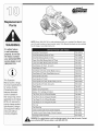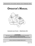
1
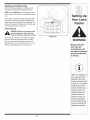
Safety • Assembly • Operation • Adjustment • Maintenance • Troubleshooting
OF
A
O
• Warranty
AL
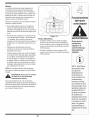
Shift=On-The=Go'" Lawn Tractor -- Models 760=779
iMPORTANT
READ SAFETY
RULES AND iNSTRUCTiONS
CAREFULLY
BEFORE
OPERATION
Warning: This unit is equippedwithan internalcombustionengineand shouldnot be usedon or nearany unimprovedforest-covered,brushcoveredor grass-coveredland unlesstheengine'sexhaustsystemis equippedwith a sparkarrestermeetingapplicablelocalor statelaws(if any).
If a sparkarresteris used,it shouldbe maintainedin effectiveworkingorder by the operator.In theState of Californiathe aboveis requiredbylaw
(Section4442 of the CaliforniaPublicResourcesCode). Otherstatesmay havesimilarlaws.Federallaws applyon federallands.A sparkarrester
for the muffleris availablethroughyour nearestengineauthorizedservicedealeror contactthe servicedepartment,RO. Box361131Cleveland,
Ohio 44136-0019.
PRINTEDIN U.S.A.
MTD LLC, P.O. BOX 361131 CLEVELAND, OHIO 44136-0019
FORMNO. 769-01598C
01/22/2007
This Operator's Manual is an important part of your new lawn tractor, it will help you assemble,
prepare and maintain the unit for best performance.
Please read and understand what it says.
Table of Contents
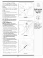
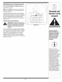
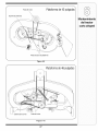
Slope Gauge ........................................................
Safe Operation Practices ...................................
Setting UpYour Lawn Tractor ............................
Operating Your Lawn Tractor ...........................
Adjusting Your Lawn Tractor ............................
3
4
8
12
20
Maintaining Your Lawn Tractor ........................
22
Off-Season Storage / Attachments ................. 28
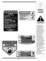
Safety Labels ....................................................
29
Trouble Shooting ..............................................
30
Warranty ..............................................
Back Page
Finding and Recording Model Number
BEFOREYOU STARTASSEMBLING YOUR NEW EQUIPMENT,
please locate the model plate on the equipment and copy the
informationto the sample model plate providedto the right. You
can locate the model plate by looking beneath the seat.
Model Number
Serial
This information will be necessary to use the manufacturer's web
site and/or obtain assistance from the Customer Support Department or an authorized service dealer.
Number
MTD LLC
P.O. BOX 361131
CLEVELAND, OH 44136
®
www.mtd prod ucts.corn
330=220=4683
800=800=731
0 j
Customer Support
Please do IVOTreturn
purchased,
without
the unit to the retailer from which it was
first contacting
Customer
Support.
If you have difficulty assembling this product or have any questions regardingthe controls, operation,or maintenanceof this
unit, you can seek help from the experts. Choose from the options below:
1. Visit www.mtdproducts.com.
2. Phone a Customer Support Representative at 1 (800) 800-7310.
3. The engine manufacturer is responsiblefor all engine-related issues with regards to performance, power-rating,specifications, warranty and service. Please refer to the engine manufacturer'sOwner's/Operator's Manual, packed separatelywith
your unit.
2
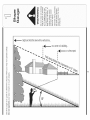
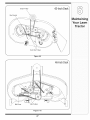
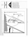
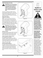
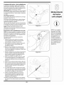
Sight and h01dthis level with a vertical tree..,
m_,_
>:.
or a corner of a building...
I
I
G.)
o9
__
(13
I
i
i
(13
or a fence post
O
do;
O
C
::>.,
--
E
c_
O
G.)
_0
o6
_--
(13
co
.oo
o
-_
G.)
O9
G.)
C
_
o9
C:_
O9
C
o
(13
-_ o_
O
C
(13
c_
0
o3
0
C
co
0
_
a
fine (repros
I _ _ er_ts a 15o
15°
WARNING: Engine Exhaust, some of its constituents, and certain vehicle components contain or emit chemicals known to State of Californiato cause cancer and
birth defects or other reproductiveharm.
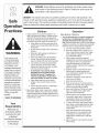
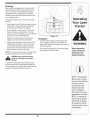
Operation
DANGER: This machine was built to be operated according to the rules for safe operation in this
manual. As with any type of power equipment, carelessness or error on the part of the operator can
result in serious injury. This machine is capable of amputating hands and feet and throwing objects.
Failureto observe the following safety instructions could result in serious injury or death.
Children
WARNING
This symbol points
out important safety
instructionswhich, if
not followed, could
i endangerthe personal
safety and/or property
ofyourself and others.
I Read and follow all
i instructions in this mani ual before attempting to
i operate this machine.
Failureto comply with
these instructions may
result in personal injury.
i Whenyou see this
symbol.
i HEED ITS WARNING
Your
i Responsibility
Restrict the use
of this power machine
I to persons who read,
understand
and follow the warnings
and instructions
in this manual
Operation
1. Tragicaccidentscanoccur if the operatoris not
alertto the presenceof children.Childrenare often
attractedto themachineand the mowingactivity.
Theydo not understandthe dangers.Neverassume
that childrenwill remainwhereyou last sawthem.
a. Keepchildrenout of the mowingarea and in
watchfulcare of a responsibleadultother than
the operator.
b. Be alert and turnmachineoff ifa childenters
the area.
Safe Handling of Gasoline:
1. Toavoid personalinjuryor propertydamageuse
extremecare in handlinggasoline.Gasolineis
extremely flammableand the vapors are explosive. Seriouspersonalinjurycan occurwhengasoline
isspilledon yourselfor yourclotheswhichcan ignite.
Washyourskin and changeclothesimmediately.
a. Use onlyan approvedgasolinecontainer.
b. Neverfill containersinsidea vehicleor on a
truckor trailerbed with a plasticliner.Always
c. Beforeand while backing,lookbehindand
placecontainerson the groundawayfrom
downfor smallchildren.
yourvehiclebeforefilling.
d. Nevercarry children,evenwith the blade(s)
c. Whenpractical,removegas-powered
shutoff.They mayfalloff and be seriously
equipmentfromthe truckor trailerand refuelit
injuredor interferewith safemachineoperation.
on the ground.If this isnotpossible,then
e. Use extremecarewhenapproachingblind
refuelsuch equipmenton a trailerwith a
corners,doorways,shrubs,trees or other
portablecontainer,ratherthan froma gasoline
objectsthat may blockyourvision of a child
dispensernozzle.
whomay run intothe machine.
d. Keepthe nozzlein contactwith the rimof
f. To avoid back-over accidents, always
the fueltank or containeropeningat all
disengagethe cuttingblade(s) before
timesuntilfuelingiscomplete.Donot usea
shiftinginto Reverse.If equipped,the
nozzlelock-opendevice.
"Reverse CautionMode"shouldnot be
e. Extinguishall cigarettes,cigars,pipesand
used when childrenor others are around.
othersourcesof ignition.
g. Keepchildrenaway from hotor running
f. Neverfuel machineindoors.
engines.They can sufferburnsfroma hot
g. Neverremovegas cap or add fuel whilethe
muffler.
engineishot or running.Allowengineto cool
h. Removekeywhenmachineis unattendedto
at least two minutesbeforerefueling.
preventunauthorizedoperation.
h. Neveroverfill fuel tank.Fill tank to no more
2. Neverallowchildrenunder 14 yearsold to operate
than1/2inchbelowbottomof filler neck to
the machine.Children14years old and overshould
allowspacefor fuel expansion.
readand understandthe operationinstructions
and
i. Replacegasolinecapand tighten securely.
safety rulesinthis manualand shouldbe trainedand
j. If gasolineis spilled,wipe it off theengine
supervisedbya parent.
and equipment.Moveunit to anotherarea.
Wait5 minutesbeforestartingtheengine.
k. Toreducefirehazards,keepmachinefreeof
grass,leaves,or otherdebris build-up.Clean
up oil or fuel spillageand removeanyfuel
soakeddebris.
I. Neverstorethe machineor fuel container
insidewherethere is an open flame,spark
or pilot lightas on a waterheater,space
heater,furnace,clothesdryeror other gas
appliances.
m. Allowa machineto cool at least five minutes
beforestoring.
4
GeneralOperation:
14.Watchfor traffic whenoperatingnearor crossing
roadways.This machineis not intendedfor useon
anypublic roadway.
15.Do notoperatethe machinewhileunderthe influenceof alcoholor drugs.
16.Mowonly in daylightor good artificiallight.
17.Nevercarry passengers.
18.Disengageblade(s)beforeshiftinginto reverse.
Back up slowly.Alwayslookdownand behindbefore
and whilebackingto avoida back-overaccident.
19.Slowdownbeforeturning.Operatethe machine
smoothly.Avoiderraticoperationand excessive
speed.
20.Disengageblade(s),set parkingbrake,stopengine
and wait untilthe blade(s)cometo a completestop
beforeremovinggrass catcher,emptyinggrass,
uncloggingchute,removingany grassor debris,or
makinganyadjustments.
21.Neverleavea runningmachineunattended.Always
turnoff blade(s), placetransmissionin neutral,set
parkingbrake,stop engineand removekey before
dismounting.
22.Useextracare whenloadingor unloadingthe
machineintoa traileror truck. This unit shouldnot
be drivenup or downramp(s),becausethe unit
couldtip over,causingseriouspersonalinjury.The
unit mustbe pushedmanuallyon ramp(s)to load or
unloadproperly.
23.Mufflerand enginebecomehotand can causea
burn.Do nottouch.
1. Read,understand,and followall instructionson the
machineand in the manual(s)beforeattemptingto
assembleand operate.Keepthis manualin a safe
placefor future and regularreferenceand for ordering
replacementparts.
2. Be familiarwith all controlsandtheir properoperation.
Knowhow to stopthe machineand disengagethem
quickly.
3, Neverallowchildrenunder 14yearsold to operate
this machine.Children14years old and overshould
readand understandthe operationinstructionsand
safety rulesin this manualand shouldbe trainedand
supervisedby a parent.
4. Neverallowadults to operatethis machinewithout
proper instruction.
5. To helpavoidblade contactor a thrownobject injury,
keep bystanders,helpers,childrenand petsat least
75 feet fromthe machinewhileit is in operation.Stop
machineif anyoneenters thearea.
6. Thoroughlyinspectthearea wheretheequipmentis to
be used. Removeall stones,sticks,wire,bones,toys,
and otherforeignobjectswhichcouldbe pickedup
and thrown bythe blade(s).Thrownobjectscancause
seriouspersonalinjury.
7. Planyourmowingpatternto avoiddischargeof
materialtowardroads,sidewalks,bystandersand the
like. Also,avoiddischargingmaterialagainsta wall or
obstructionwhich maycause dischargedmaterialto
ricochetback towardthe operator.
8. Alwayswear safetyglassesor safetygogglesduring
operationand while performingan adjustmentor
repairto protectyoureyes.Thrownobjectswhich
ricochetcancause seriousinjuryto the eyes.
9. Wearsturdy,rough-soledwork shoesand close-fitting
slacks and shirts. Loosefittingclothesandjewelry
can be caught in movableparts.Neveroperatethis
machinein barefeet or sandals.
24.Checkoverheadclearancescarefullybeforedriving
under lowhangingtreebranches,wires,dooropeningsetc., wheretheoperatormaybe struckor pulled
fromthe unit,which couldresult in seriousinjury.
25.Disengageall attachmentclutches,depressthe
brakepedalcompletelyand shift into neutralbefore
attemptingto startengine.
26.Yourmachineisdesignedto cut normalresidential
grassof a heightno morethan 10".Do notattemptto
mowthroughunusuallytall, dry grass (e.g.,pasture)
or pilesof dry leaves.Dry grass or leavesmay
contactthe engineexhaustand/orbuild up on the
mowerdeck presentinga potentialfire hazard.
27.Use onlyaccessoriesand attachmentsapprovedfor
this machinebythe machinemanufacturer.Read,
understandand followall instructionsprovidedwith
the approvedaccessoryor attachment.
28.Data indicatesthat operators,age 60 yearsand
above,are involvedin a largepercentageof riding
mower-relatedinjuries.Theseoperatorsshould
evaluatetheirability to operatethe ridingmower
safelyenoughto protectthemselvesand othersfrom
seriousinjury.
29.If situationsoccurwhich are not coveredin this
manual,usecareand good judgment.Contactyour
customerservicerepresentativefor assistance.
10.Be awareof the mowerand attachmentdischarge
directionand do not pointit at anyone.Donot operate
the mowerwithoutthe dischargecoveror entiregrass
catcherin its properplace.
11.Donot put handsor feet near rotatingpartsor under
the cuttingdeck. Contactwith the blade(s)can
amputatehandsand feet.
12.A missingor damageddischargecovercan cause
blade contactor thrown objectinjuries.
13.Stop the blade(s)whencrossinggraveldrives,walks,
or roadsand whilenot cuttinggrass.
!i!i
¸¸¸:¸/:
:!i ¸ ¸¸¸ :
:
WARNING
This symbol points
out important safety
instructions which, if
not followed, could
endanger the personal
safety and/or property
of yourself and others.
Read and follow all
instructions in this manual before attempting to
operate this machine.
Failureto comply with
these instructions may
result in personal injury.
When you see this
symbol.
HEED ITS WARNING
Your
Responsibility
Restrictthe use
of this power machine
to persons who read,
understand
and follow the warnings
and instructions
in this manual
5
Do Not:
Operation
This symbol points
out important safety
instructions which, if
not followed, could
endangerthe personal
i safety and/or property
of yourself and others.
Read and follow all
=nstructionsin this man-
Slopesare a majorfactor relatedto loss of controland
tip-overaccidentswhich can resultin severeinjuryor
death.All slopesrequireextracaution.If youcannot
back up the slopeor if youfeel uneasyon it, do notmow
it.
Foryour safety,usethe slopegaugeincludedas partof
this manualto measureslopesbeforeoperatingthis unit
on a slopedor hillyarea. If the slopeis greaterthan 15
degreesas shownon theslopegauge,do notoperate
this unit on that area or seriousinjurycouldresult.
DO:
1. Do notturn on slopesunlessnecessary;then,turn
slowlyand graduallydownhill,if possible.
2. Do not mownear drop-offs,ditchesor embankments.
Themowercouldsuddenlyturnoverif a wheel is over
the edgeof a cliff, ditch,or if an edge cavesin.
3. Do nottry to stabilizethe machineby puttingyourfoot
on the ground.
4. Do not usea grasscatcheron steep slopes.
5. Do not mowon wet grass. Reducedtractioncould
causesliding.
6. Do not shiftto neutraland coastdownhill.Over-speeding may causethe operatorto losecontrol of the
machineresultingin seriousinjuryor death.
7. Do nottow heavypull behindattachments(e.g.loaded
dumpcart, lawnroller,etc.)on slopesgreaterthan
5 degrees.Whengoingdown hill,the extra weight
tendsto pushthe tractorand may causeyou to loose
control.(e.g. tractormayspeedup, brakingand steering ability are reduced,attachmentmayjack-knifeand
causetractorto overturn).
1. Mow up and downslopes,notacross. Exercise
extremecautionwhenchangingdirectionon slopes.
2. Watchfor holes, ruts,bumps,rocks,or other hidden
objects.Uneventerraincouldoverturnthe machine.
Tallgrasscan hide obstacles.
3. Use slow speed.Choosea low enoughspeed
settingso that youwill not haveto stopor shift while
on the slope.Tires may losetractionon slopeseven
thoughthe brakesare functioningproperly.Always
keepmachinein gear whengoingdown slopesto
take advantageof engine brakingaction.
4. Followthe manufacturer'srecommendations
for
wheelweightsor counterweightsto improvestability.
5. Use extracare with grasscatchersor otherattachments.Thesecanchangethe stabilityof the
machine.
Towing:
1. Towonlywith a machinethat hasa hitch designedfor
towing.Donot attachtowedequipmentexceptat the
hitch point.
2. Followthe manufacturersrecommendationfor weight
limitsfor towedequipmentand towingon slopes.
3. Neverallowchildrenor othersin or on towedequipment.
6. Keepall movementon the slopesslowand gradual.
Do not makesuddenchangesin speedor direction.
Rapidengagementor brakingcouldcausethe front
of the machineto lift and rapidlyflip overbackwards
whichcouldcause seriousinjury.
7. Avoidstartingor stoppingon a slope.If tires lose
traction,disengagethe blade(s)and proceedslowly
straightdownthe slope.
4. On slopes,the weightof the towedequipmentmay
causeloss of tractionand loss of control.
5. Travelslowlyand allowextra distanceto stop.
6. Do not shiftto neutraland coastdownhill.
ual before attempting to
I operate this machine.
I Failureto comply with
i these instructions may
i result in personal injury.
When you see this
symbol.
HEED ITS WARNING
Your
Responsibility
Restrict the use
of this power machine
to persons who read,
understand
and follow the warn=ngs
and instructions
in this manual
6
Service
10.Neverattemptto makeadjustmentsor repairsto the
machinewhilethe engine isrunning.
1. Neverrun an engineindoorsor in a poorlyventilated
11.Grasscatchercomponents
and the discharge
area. Engineexhaustcontainscarbonmonoxide,an
coverare
subjectto
wearand
damagewhich could
odorless,and deadlygas.
exposemovingpartsor allowobjectsto be thrown.
2. Beforecleaning,repairing,or inspecting,makecertain
Forsafety protection,frequentlycheckcomponents
the blade(s)and all movingparts havestopped.
and replaceimmediatelywith originalequipment
Disconnectthe sparkplug wireand groundagainstthe
manufacturer's(O.E.M.)parts only,listed in this
engineto preventunintendedstarting.
manual."Useof parts which do not meetthe original
3. Periodicallycheckto make surethe bladescome to
equipmentspecificationsmay leadto improper
completestop withinapproximately(5) five seconds
performanceand compromisesafety!"
after operatingthe bladedisengagementcontrol.If the
12.Do notchangethe enginegovernorsettingsor
bladesdo notstop within thethis timeframe,yourunit
over-speedthe engine.Thegovernorcontrolsthe
shouldbe servicedprofessionallyby an authorized
maximumsafe operatingspeedof the engine.
MTDServiceDealer.
13.Maintainor replacesafety and instructionlabels,as
4. Checkbrakeoperationfrequentlyas it is subjectedto
necessary.
wearduring normaloperation.Adjustand serviceas
14.Observeproperdisposallawsand regulationsfor
required.
gas, oil,etc. to protecttheenvironment.
5. Checkthe blade(s)and enginemountingbolts at
frequentintervalsfor propertightness.Also,visually
inspectblade(s)for damage(e.g.,excessivewear,
bent, cracked). Replacethe blade(s)with theoriginal
equipmentmanufacturer's(O.E.M.)blade(s)only,
listed inthis manual."Useof partswhich do not meet
the originalequipmentspecificationsmaylead to
improperperformanceand compromisesafety!"
6. Mowerbladesare sharp.Wrapthe bladeor wear
gloves,and useextra cautionwhenservicingthem.
7. Keepall nuts, bolts,and screwstight to be surethe
equipmentis insafe workingcondition.
8. Nevertamperwith the safety interlocksystemor other
safety devices.Checktheir properoperationregularly.
9. After strikinga foreignobject,stop the engine,
disconnectthe spark plug wire(s)and groundagainst
the engine.Thoroughlyinspectthe machinefor any
damage.Repairthe damagebeforestartingand
operating.
This symbol points
out important safety
instructions which, if
not followed, could
endangerthe personal
safety and/or property
of yourself and others.
Read and follow all
instructions in this manual before attempting to
operate this machine.
Failureto comply with
these instructions may
result in personal injury.
When you see this
symbol.
HEED iTS WARNING
Your
Responsibility
Restrictthe use
of this power machine
to personswho read,
understand
and follow the warn=ngs
and instructions
in this manual
7
NOTE:This OperatorsManualcoversa rangeof product
specificationsfor variousmodels.Characteristicsand featuresdiscussedand/orillustratedin this manualmay not
be applicableto all models.MTDLLCreservesthe right
to changeproductspecifications,designsand equipment
withoutnotice and withoutincurringobligation.
Rubber Boot
Attaching
the Battery
Cables
NOTE:Somemodelsare shippedwith the batterycables
alreadyconnected.
NOTE:Thepositivebatteryterminalis markedPos. (+).
Thenegativebatteryterminalis markedNeg. (-).
• Thepositivecable(heavy redwire) is securedto the
positivebatteryterminal(+)with a hexbolt and hex
nut at thefactory.Makecertainthat the rubberboot
coversthe terminalto help protectit fromcorrosion.
• Removethehex boltand hexnut fromthe negative
cable.
Use extreme care
Removetheblack plasticcover,ifpresent,from the
negativebatteryterminaland attachthe negative
cable(heavy blackwire)to the negativebattery
terminal(-) with thebolt and nut.
Figure 3-1
henhandling
gaso nel
Gasoline
extremely flammable
and the vapors are
NOTE:If the batteryis putinto serviceafter the date
shownon top/sideof battery,chargethe batteryas
instructedin the MaintainingYour LawnTractorsectionof
this manualpriorto operatingthe tractor.
explosive: Never fuel
machine indoors
or while the engine
is hot or running:
Gas and Oil Fill-up
Thegasolinetank is locatedunderthe hood and hasa
capacityof 1-1/2gallons.Donot overfill.
Extinguish cigarettes,
cigars;
pipes,
and
other sOurceS of
_
ignition:
handling
gasoline.
Gasoline
extremely
WARNING:
Use extreme
careiswhen
flammable and the vapors are explosive.
Never fuel machine indoors or while the
engine is hot or running. Extinguish cigarettes, cigars, pipes, and other sources of
ignition.
Servicethe enginewith gasolineand oil as instructedin
the separateEngineOperator/OwnerManualpackedwith
yourtractor.Readinstructionscarefully.
NOTE: This Operators
Manual Coversa range
of prOduCtSpecifications
IMPORTANT:Yourtractorisshippedwith motoroil inthe
engine.However,you MUSTcheckthe oil levelbefore
operating.Be careful notto overfill.
for various models.
Characteristicsand
features disCussed
and/or illustrated
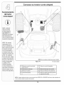
Shipping
Brace
Removal
WARNING:Make sure the riding mower's
engine is off, removethe ignition key,and
set the parking brake before removing the
shipping brace.
this manual may not be
applicable to all modelsl
MTD LLC reservesthe
right tOchange product
I
specifiCationsldesigns
and equipment without
notice and without incurting oblieation
,,
8
Locatethe shippingbrace,if present,and accompanying warningtag foundon the rightside of the mower,
betweenthe dischargechuteand thecuttingdeck.
See Fig.3-2.
Whileholdingthe dischargechute with yourleft hand,
removethe shippingbracewith your righthandby
graspingit betweenyour thumband indexfingerand
rotatingit clockwise.
YourLawn
Tractor
WARNING: Theshipping brace, used
for packaging purposes only, must be
removed and discarded before operating
your riding mower.
WARNING: Themowing deck is capable
of throwing objects. Failure to operate the
riding mower without the discharge cover
in the proper operating position could
result in serious personal injury and/or
property damage.
Attaching
The Steering
Figure 3=2
Wheel
Make sure the riding
mower's engine is
off, remove the ignition key, and set the
parking brake before
removing the shipping
brace.
ifthe steeringwheelforyour tractordid notcome
attached,the hardwarefor attachingit hasbeen packed
within the steeringwheel,beneaththe steeringwheel
cap. Carefullypry off the steeringwheelcapand remove
the hardware.
1. With the wheels of the tractor pointingstraight
forward, placethe steeringwheeloverthe steering
shaft.
The shipping brace,
used for packaging
purposes only, must
be removed and
discarded before
2. Placethe washer(with thecuppedsidedown)over
the steeringshaftand securewith the hex bolt. See
Fig.3-3.
3. Placethe steeringwheelcap overthe centerof the
steeringwheeland pushdownwarduntilit "clicks"into
place.
operating your riding
mower.
Attaching
the Hood Scoop
(if so equipped)
Figure 3=3
If the hood scoopwas not securedto the hoodof your
tractorat the factory,you willfind it in a plasticbag,
hangingfrom the throttlelever.
To install:
The mowing deck is
capable of throwing
objects. Failure to
operate the riding
mower without the
discharge cover in
the proper operating
position could result
in serious personal
injury and/or property
damage.
1. Carefullypivot thetractor hoodforward.
2. Removethe fourscrewsfrom the undersideof the
hood scoop.
.
WARNING
Lineup thefour holesin the hoodscoop with thefour
holes visiblethroughthe tractor'shood Iouvres.See
Figure3-4.
4. Whileholdingthe scoop in place,usea 3/8" socket
wrench(or boxwrench)to carefullytightenthe scoop
ontothe hood.
Do NOTovertighten.
Figure 3-4
9
Attaching
The Seat
Seatstyles vary bytractormodeland thereare three
differentstyles available:
StandardAdjustment
•
QuickAdjustment&
•
KnobAdjustment
If the seatfor yourtractorwas notattachedat the factory,
referto Fig. 3-5, Fig. 3-6, and Fig. 3-7 to identifyyour
tractor'sseatstyle and followthe applicableinstructions
belowto attachit.
Figure 3-5
NOTE:Forshippingreasons,seatsare eitherfastened
to the tractorseat'spivot bracketwith a plastictie, or
mountedbackwardto the pivot bracket.Ineithercase,
freethe seat form its shippingpositionand removethe
two hex screws(or knobs,on modelsso equipped)from
the bottomd seatbeforeproceedingwith applicable
instructionsbelow.
Standard Adjustment Seat
1. Positionthe shoulderscrews(foundon the based the
seat) insidetheslot openingsin the seat pivot bracket.
Fig. 3-5.
2. Slide the seatslightlyrearwardin the seat pivot
bracket,liningup the rearslots in the pivot bracket
with the remainingtwo holesin the seat'sbase.
the seat is engaged in
the seatstop;
stand
behind
themachine
3. Selectdesiredpositionforthe seat,and securewith
the two hex screwsremovedearlier.See Fig.3-5.
and back
onseat
until fully engaged
i
Quick Adjustment Seat
NOTE:ifyour seatwas shippedmountedbackwardson
the seat pivotbracket,pull outthe tab foundon the seat
stop and hold itopen whileslidingthe seatoff the seat
pivot bracket.See Fig. 3-6.
into stopl
1. Line up the plasticseat spacerswith the slotsin seat
pivot bracket.
NOTE: Forshipping rea-
Figure 3-6
2. Slide seat in untilfront seat spacerengagesthe seat
stop.See Fig. 3-6.
sons seats are either
fastenedtothe tractor
bi_ make surestop,WARNINGstand
:theseat
behindthe
Bef°re
operating
is engaged
machine
thismachine,seat
inand
thepull
seat's pivot bracket with
back on seat until fully engaged into stop.
a plastiCtie,or mounted
backward tothe pivot
bracketl either case;
freethe seat formits
shipping position and
Knob Adjustment Seat
1. Positionthe shoulderscrews(foundon the based the
seat) insidetheslot openingsin the seat pivot bracket.
Fig. 3-7.
2. Slide the seatslightlyrearwardin the seat pivot
bracket,liningup the rearslots in the pivot bracket
with the remainingtwo holesin the seat'sbase.
3. Selectdesiredpositionforthe seat,and securewith
the two knobs removedearlier.See Fig.3-7.
applicable instructions
Figure 3-7
10
identifying
the lVluich Plug
On tractormodelssoequipped,a mulchplug can be
foundwithin thecuttingdeck'sdischargeopening.
....,\\\\\
NOTE:Referto Mulching in the"OperatingYour Lawn
Tractor"sectionof this manualfor moredetailedinformation.
Setting Up
If you'dpreferto operatethe cuttingdeck withoutmulching, simplyremovethe mulch plugby unthreadingthe
plasticwing nutwhich fastensit to the cuttingdeck.This
will allowthe clippingsto dischargeout of the discharge
openingduringoperation.See Fig.3-8.
Tire Pressure
,_
any
circumstances is 30
Equal under
tire
WARNING:Maximum
tirepsL
pressure
pressure should be maintained at all times.
Figure 3=8
The tires on your unitmay be over-inflatedfor shipping
purposes.Reducethetire pressurebeforeoperating
the tractor.Recommendedoperatingtire pressureis
approximately10 p.s.ifor the rear tires & 14p.s.i,for the
front tires.Checksidewallof tirefor maximump.s.i.
WARNING
Maximum tire pres'
sure under any
circumstances is 30
psi, Equal tire pressure
should be maintained
at all times,
NOTE: For shipping red:
sons, seats are either
fastened tothe tractor
Seats
_ pivot bracket With
a plastic tie, or mounted
backwardto the pivot
brackeL In eithercase
free the seat form its
shipping position and
removethe two hex
screws(or knobs; on
models so equipped)
from the bottom of seat
before proceedingwith
p#
le instructions:
11
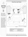
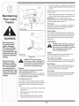
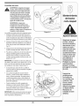
Know Your Lawn Tractor
A
\
NOTE:Anyreference
inthismanualto the
RIGHTor LEFTsideof
thetractorisobserved
fromoperator's
position.
NOTE:Forshippingreasons,seatsareeither
fastenedtothetractor
seat'spivotbracketwith
a plastictie,or mounted
backward
tothepivot
bracket.Ineithercase
freetheseatformits
shippingpositionand
remove
thetwohex
screws(orknobs,on
modelssoequipped)
fromthebottomofseat
beforeproceeding
with
applicable
instructions.
NOTE:Steeringwheelnot shownfor clarity
Figure 4=1
1-If soequipped
A
SpeedControlLever/ParkingBrake
E
ThrottleControlLever
B
Clutch-BrakePedal
F
IgnitionSwitchModule
C
Shift Lever
G
DeckLift Lever
D
ChokeControl1-
H
PTO(Blade Engage)Lever
NOTE:Anyreferencein this manualto the RIGHTor LEFTside of the tractoris observedfrom operator'sposition.
12
m
Throttle
Control
F
Lever
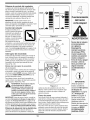
Thethrottlecontrol leveris locatedon the rightside of
thetractor'sdash panel.This levercontrolsthe speed
of the engineand,on somemodels,when pushedall
theway forward,the chokecontrol also.Whenset ina
givenposition,the throttlewill maintaina uniformengine
speed.See Fig. 4-2.
FAST
CHOKE
|l
FAST
iMPORTANT:Whenoperatingthetractorwith the cutting
deck engaged,be certainthat the throttleleverisalways
in the FAST(rabbit)position.
Choke
Control
On some models,movingthe
throttleleverall the way forward
activatestheengine'schoke
control.On all othermodels,the
chokecontrolcan be foundon
SLOW
SLOW
Figure 4=2
the leftside of thedash panel
and isactivatedby pullingthe
knoboutward.Activatingthe
chokecontrolclosesthe choke
_A
Off
plateon the carburetorand aids
in startingthe engine.Referto Starting The Engine on
page 16of this manualfor detailedstartinginstructions.
On/Lights
Ignition Switch
The ignitionswitchisactivatedto startthe engine,insert
key intothe ignitionswitchand turnclockwiseto the
STARTposition.Releasethe key intothe ON position
onceengine hasfired. See Fig.4-3A.
Start
ignition Switch Module (If So Equipped)
Tostart theengine,insertthe key intothe ignitionswitch
and turnclockwiseto the STARTposition.Releasethe
key intothe NORMALMOWINGMODEpositiononce
theengine hasfired.
Tostop the engine,turn theignitionkey counterclockwise
to the OFF position.See Fig. 4-3B.
Stop
Position
WARNING: Never leave a running machine
unattended. Always disengage PTO,move
shift lever into neutral position, set parking brake, stop engine and remove key to
prevent unintended starting.
©
Foundon yourtractor'srightfender,the deck lift leveris
usedto changetheheightof the cuttingdeck.To use,
movethe leverto the left,then placein the notchbest
suitedfor yourapplication.
Start
Position
MPORTANT
Prior_o0
iMPORTANT:Priorto operatingthetractor,referto both
Safety interlock Switches on page 14and Starting
The Engine on page 16 of this manualfordetailed
instructions
regardingthe ignitionSwitchModuleand
operatingthe tractorin REVERSECAUTIONMODE.
Deck Lift Lever
_ever leave a running
machine unattended,
Always disengage
PTO, move shift lever
nto neutral position,
set parking brake, stop
engine and remove key
to prevent unintended
starting:
tractori refe!to both
Figure 4-3
Parking
Brake
To set the parkingbrake,fully depressthe dutch-brake
pedal.Movethe speedcontrolleverall theway downand
intothe parkingbrakeposition.Releasethe clutch-brake
pedalto allowthe parkingbraketo engage.
To releasethe parkingbrake,depresstheclutch-brake
pedaland movethe speedcontrolleveroutof the
notchesto thedesiredposition.Releasethespeed
control leverand the clutch-brakepedal.
Safety Interlock
;
Switches onpage
14. and starting The
:Engine
onpage16
detailedinstraCtions
regardingtheIgnition
Switch Module and
operating the tractor in
REVERSE CAUTION
ODEi
13
NOTE:Lawntractorsvary by modeland are availablewith
eithera 6- or 7-speedcontrollever.
PTO (Blade Engage)
FRRWARD
NUETRAL
Safety
REVERSE_
Figure 4-4
WARNING
Dooctop rato
tractor ifthe interlock
ing: This system was
NOTE:Theparkingbrakemustbe set if theoperator
leavesthe seatwith the engine runningor the engine
willautomaticallyshut off.
Clutch-Brake
Pedal
safety
aodproteot oo,
Lever
The shiftleverislocatedon the left sideof thefender
NOTE: Theparking
brakemustbesetifthe
operator leaves the seat
with theengine
ning or the enginewi
automatiCallyshut ofL
NOTE: The PTO (Blade
Engage) lever must be
inthe disengaged (PTO
OFF) position when
starting the engine:
IMPORTANT
Never force the shift
lever:Do ngso may
result in serious
damage to the tractorls
transmissionl
and hasthree positions,FORWARD,NEUTRALand
REVERSE.The brakepedal mustbe depressedand
thetractor mustnotbe in motionwhenthe movingshift
lever.See Fig. 4-4.
IMPORTANT:Neverforce the shiftlever.Doingso may
result inseriousdamageto the tractor'stransmission.
Speed
Control
Lever
The speedcontrollever,locatedon
the leftside of thetractor'sdash
console,allowsyouto regulatethe
groundspeedof the lawntractor.To
use, depressthe clutch-brakepedal
and movethe leveroutof the parking
brakenotchand forwardto increase
thetractor'sgroundspeed.Whena
desiredspeedhas been reached,
releasethe leverintoan appropriate
notchto maintainthat speed.
Toslow thetractor'sgroundspeed,
depressthe clutch-brakepedaland
movethe speedcontrolleverrearward
and releaseit intoa notch.
0
Interlock
"O /"
!2
o
_3
m
_4
!
"o
,t5
Switches
This tractorisequippedwith a safetyinterlocksystem
for the protectionof the operator,if the interlock
system
shouldever malfunction,do not operatethe tractor.
Contactan authorizedMTDservicedealer.
Theclutch-brakepedal is locatedon the left sideof
the lawntractor,along the runningboard.Depressthe
*
clutch-brakepedalpartway downwhenslowingthe
tractorbychangingspeeds(Referto SpeedControl
*
Lever).Depressthe pedalall theway downto engage
thedisc brakeand bringthe tractorto a completestop.
NOTE:Thepedal mustbe depressedto startthe engine.
Referto SafetyInterlockSwitcheson page 14.
*
Shift
Lever
Foundon the tractor'srightfender,the
PTO(bladeengage)leveris usedto
engagepowerto the cuttingdeck or
other(separatelyavailable)attachments.
Tooperate,movethe leverall the way
forward.Movingthe leverall the way
rearwardintothe PTOOFF position
disengagespowerto the cuttingdeck/
attachment.
NOTE:The PTO(blade engage)lever
mustbe in the disengaged(PTOOFF)
positionwhenstartingthe engine.
Thesafety interlocksystempreventstheengine
fromcrankingor startingunlessthe parkingbrakeis
engaged,andthe PTO(BladeEngage)leveris in the
disengaged(OFF) position.
Theenginewill automaticallyshut off if the operator
leavesthe seat beforeengagingthe parkingbrake.
Theenginewill automaticallyshut off if the operator
leavesthe tractor'sseat with the PTO(Blade Engage)
leverin the engaged(ON) position,regardlessof
whetherthe parkingbrakeis engaged.
Theenginewill automaticallyshut off if the operator
engagesthe PTOwith the parkingbrakeON.
Models without
Reverse Caution Mode
,, Theenginewill automaticallyshut off if the PTO(Blade
Engage)leveris movedinto the engaged(ON) position
with the shift leverin Reverse.
Models with Reverse Caution Mode
* With the ignitionkey in the NORMALMOWINGposition, the enginewillautomaticallyshut off if the PTO
(Blade Engage)leveris movedintothe engaged(ON)
positionwith the shift leverin Reverse.
_
0
PARK
BRAKE
14
interlock
system
is operate
malfunctioning.
This
ARNING:
Do not
the tractor
if the
system was designed for your safety and
protection.
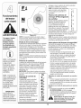
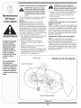
Reverse Caution Mode
(Models equipped with ignition
module)
_il=
switch
Reverse
. PushButton
Indicator
Light
operating
the tractor
in the
REVERSE
ARNING:Use
extreme
caution
while
CAUTIONMODE.Always look down and
behind before and while backing. Do
not operate the tractor when children
or others are around. Stop the tractor
immediately if someone enters the area.
Reverse
Caution Mode
Position
Stop
Position
©
The REVERSECAUTIONMODE positionof the key
switchmoduleallows thetractorto be operatedin
reversewith the blades(PTO)engaged.
Start
Position
I
IMPORTANT:Mowingin reverseis notrecommended,
Tousethe REVERSECAUTIONMODE:
Figure 4-5
IMPORTANT:The operatorMUSTbe seatedin the
tractorseat.
To releasethe parkingbrake:
1. Depressthe clutch-brakepedaland movethe speed
control leverout of the parkingbrakepositionand into
a desiredspeed.
1, Start the engineas instructedon page 16under
Starting The Engine.
2. Turnthe key from the NORMALMOWING(Green)
positionto the REVERSECAUTIONMODE(Yellow)
positionof the key switchmodule. See Fig. 4-5.
Setting
the Cutting
Height
1. Selectthe heightpositionof the cuttingdeck by placingthe deck lift leverinany of the six differentcutting
heightnotcheson the rightsideof thefender.
3. Depressthe REVERSEPUSHBUTTON(Orange,
TriangularButton)at the top, rightcornerof the key
switchmodule.The red indicator
lightat thetop, left
cornerof the keyswitch modulewill be ONwhile
activated.See Fig.4-5.
2. Adjustthe deck wheels,ifequipped,sothat theyare
between1A-inchand V2-inchabovethe groundwhen
the tractoris on a smooth,flat surfacesuch as a
driveway.
4. Onceactivated(indicatorlight ON), thetractorcan
be drivenin reversewith the cuttingblades(PTO)
engaged.
d_ltlb
5. Alwayslookdownand behindbeforeand while
backingto makesureno childrenare around.
NOTE:On modelssoequipped,the deck wheelsare an
anti-scalpfeatureof the deck and are notdesignedto
supportthe weightof the cuttingdeck.
6. After resumingforwardmotion,returnthe key to the
NORMALMOWINGposition.
Referto Levelingthe Deckon page20 of this manual
for moredetailedinstructions
regardingvariousdeck
adjustments.
IMPORTANT:The REVERSECAUTIONMODEwill
remainactivateduntil:
a. Thekey is placedin eitherthe NORMALMOWING
positionor STOPposition.
b. Theoperatorengagesthe parkingbrakebyfully
depressingtheclutch-brakepedal and holdingit
downwhilemovingthe speedcontrol leverintothe
PARKBRAKEposition.
Engaging
the Parking
the
discharge
opening
thefeet
cutting
WARNING
: Keep
handsofand
awaydeck.
from
Use extreme caution
while operating
the tractor in the
REVERSE CAUTION
MODE. Always look
down and behind
before and while
backing. Do not operate the tractor when
children or others
are around. Stop the
tractor immediately if
someone enters the
area.
Keep hands and
feet away from the
discharge opening of
the cutting deck.
Do not operate
the tractor if the
Brake
interlock system is
malfunctioning. This
system was designed
for your safety and
protection.
Toengagethe parkingbrake:
1. Fullydepressthe clutch-brakepedaland hold it down
with yourfoot.
2. Movethe speedcontrolleverall the way downand
intothe parkingbrakeposition.
3. Releasethe clutch-brakepedalto allowthe parking
braketo engage.
15
Starting
_
the Engine
WA
the
interlock system
is malfunctioning.
ARNING:Do
not operate
the tractor if
This system was designed for your safety
and protection.
AVOID SERIOUS INJURY OR DEATH
GO UPAND DOWNSLOPES,NOT ACROSS.
NOTE:Referto the TRACTORSET=UPon page8 of
this manualfor Gasolineand Oil fill-upinstructions.
AVOIDSUDDENTURNS.
DO NOT OPERATETHE UNITWHERE IT COULDSLIP OR TIR
1. Insertthe tractorkey intothe ignitionswitch.
IF MACHINE STOPSGOINGUPHILL,STOP BLADE(S) AND
BACK DOWNHILLSLOWLY.
2. Placethe PTO(Blade Engage)leverin the disengaged(OFF) position.
DO NOT MOWWHEN CHILDRENOROTHERS AREAROUND.
3. Engagethetractor'sparkingbrake.
NEVER CARRYCHILDREN,EVENWITH BLADESOFR
4. Activatethe chokecontrol.
LOOK DOWNAND BEHIND BEFOREAND WHILE BACKING.
5. Turnthe ignitionkey clockwiseto the STARTposition. Afterthe engine starts,releasethe key.It will
returnto the ON(or NormalMowing)position.
KEEP SAFETY DEVICES(GUARDS,SHIELDS,AND SWITCHES)
IN PLACEAND WORKING.
REMOVEOBJECTSTHAT COULDBE THROWNBYTHE
IMPORTANT:DoNOThold the key in the START
positionfor longerthanten secondsat a time. Doingso
maycause damageto yourengine'selectricstarter.
WARNING
PLACING HANDSOR FEETNEAR BLADE(S).
BEFORE LEAVINGOPERATOR'SPOSITION,DISENGAGE
Avoid sudden starts,
ex-cessive speed and
sudden stops.
1. If the bladesare engaged,placethe PTO(Blade
Engage)leverin the disengaged(OFF)position.
and while backing up
to avoid a back-over
KNOW LOCATIONAND FUNCTIONOF ALL CONTROLS.
BE SURE BLADE(S) AND ENGINEARE STOPPEDBEFORE
NOTE:Do NOTleavethe chokecontrolon while operating the tractor.Doingsowill result in a "rich" fuelmixture
and causethe engineto run poorly.
Always look down
and behind before
BLADE(S).
6. Afterthe engine starts,deactivatethe chokecontrol
and placethe throttlecontrol in the FASTposition.
if you strike a foreign
object, stop the engine,
disconnect the spark
plugwire(s) and
ground against the
engine.Thoroughly
inspectthe machine for
any damage. Repair the
damage before restartingand operating.
Do not leavethe seat
of the tractor without
first placingthe PTO
(Blade Engage)lever in
the disengaged (OFF)
position, depressing
the brake pedal and
engagingthe parking
brake. If leaving the
tractor unattended, also
turn the ignitionkey off
and remove the key.
I
Stopping
_
stop
the engine,
the spark
ARNING:
If youdisconnect
strike a foreign
object,
plug wire(s) and ground against the
engine. Thoroughly inspect the machine
for any damage. Repair the damage
before restarting and operating
3. Removethe keyfrom the ignitionswitch to prevent
unintendedstarting.
_
BRAKE LOCK, SHUT ENGINEOFF AND REMOVEKEY.
READ OPERATOR'S
MANUAL
the Engine
2. Turnthe ignitionkey counterclockwiseto the STOP
position.
Driving
BLADE(S), PLACETHE SHIFT LEVERIN NEUTRAL,ENGAGE
The Tractor
sive speed and sudden
stops.
WARNING:Avoid
sudden
starts, ex-cesWARNING: Do not leave the seat of the
tractor without first placing the PTO
(Blade Engage) lever in the disengaged
(OFF)position, depressing the brake
pedal and engaging the parking brake. If
leaving the tractor unattended, also turn
the ignition key off and remove the key.
Always look down and behind before and
while backing up to avoid a back-over
accident.
1. Depressthe brakepedalto releasethe parkingbrake
and let the pedal up.
2. Movethe throttleleverintothe FAST(rabbit)position.
3. Placethe shift leverin eitherthe FORWARDor
REVERSEposition.
IMPORTANT:Do NOTusethe shift leverto changethe
directionof travelwhenthe tractoris in motion.Always
use the brakepedal to bring thetractorto a completestop
beforeshifting.
4. Releasethe parkingbrakebydepressingthe clutchbrakepedaland positioningthe speedcontrol leverin
desiredposition.
IMPORTANT:First-timeoperatorsshoulduse speedpositions 1 or 2. Becomecompletelyfamiliarwith the tractor's
operationand controlsbeforeoperatingthetractorin
higher speedpositions.
.
Releaseclutch-brakepedal slowlyto put unitinto
motion.
6. The lawntractoris broughtto a stop by depressingthe
clutch-brakepedal.
NOTE:Whenoperatingthe unitinitially,therewill be little
differencebetweenthe highesttwo speedsuntilafter the
belts haveseatedthemselvesintothe pulleysduringthe
break-inperiod.
16
WARNING: Before leavingthe operator's
positionfor any reason,disengage the
blades, place the shift lever in neutral,
engage the parking brake, shut engine off
and remove the key.
Engaging
the Blades
Engagingthe PTO(BladeEngage)transferspowerto the
cuttingdeck or other(separatelyavailable)attachments.
Toengagetheblades, proceedas follows:
1. Movethe throttlecontrol leverto the FAST(rabbit)
position.
iMPORTANT:Whenstoppingthe tractorfor any reason
whileon a grass surface,always:
2. Graspthe PTO(Blade Engage)leverand pivot it all
theway forwardintothe engaged(ON)position.
1. Placethe shiftleverin neutral,
3. Keepthe throttleleverinthe FAST(rabbit)position
forthe mostefficient useof the cuttingdeck or other
(separatelyavailable)attachments.
2. Engagethe parkingbrake,
3. Shutengineoff and removethe key.
Doingso will minimizethe possibilityof havingyourlawn
"browned" byhot exhaustfrom yourtractor'srunning
engine.
If unit stalls with speedcontrolin high speed,or if unit
will notoperatewith speedcontrol leverin a low speed
position,proceedas follows:
1. Placeshift leverin NEUTRAL.
iMPORTANT:Modelswith ReverseCaution Mode:
Theenginewill automaticallyshutoff if the PTOis
engagedwith the shift leverinpositionfor reversetravel
with theignitionkey in the NORMALMOWINGposition.
Modelswithout ReverseCaution Mode:
3. Placespeedcontrolleverin highestspeedposition.
The PTO(Blade Engage)levermustbe in the disengaged(OFF)positionwhenstartingthe engine,when
travelingin reverse,and if theoperatorleavesthe seat.
Referto SafetyInterlockSwitcheson page 14.
4. Releaseclutch-brakepedalfully.
Using
5. Depressclutch-brakepedal.
Toraisethe cuttingdeck,movethe deck lift leverto
theleft, then placeitin the notchbest suitedfor your
application.Referto SettingThe CuttingHeightearlierin
this section.
2. Restartengine.
6. Placespeedcontrolleverin desiredposition.
7. Placeshift leverin eitherFORWARDor REVERSE,
and follownormaloperatingprocedures.
Driving
On Slopes
Referto the SLOPEGAUGEon page3 to helpdetermine
slopeswhereyoumay operatethe tractorsafely.
WARNING: Do not mow on inclines with
a slope in excessof 15degrees (a rise of
approximately 2-1/2 feet every 10 feet). The
tractor could overturn and cause serious
o
o
injury.
Mow up and downslopes,NEVERacross,
Exerciseextremecautionwhenchangingdirectionon
slopes,
Watchfor holes, ruts,bumps,rocks,or otherhidden
objects.Uneventerraincouldoverturnthe machine,
Tallgrasscan hide obstacles.
Avoidturns whendrivingon a slope. If a turn mustbe
made,turndownthe slope. Turningup a slopegreatly
increasesthe chanceof a roll over,
Avoidstoppingwhendrivingup a slope, if it is
necessaryto stop whiledrivingup a slope, startup
smoothlyand carefullyto reducethe possibilityof
flippingthe tractoroverbackward.
17
WARNING
the Deck Lift Lever
Do not mow on
inclineswith a slope
in excess of 15
degrees (a rise of
approximately 2-1/2
feet every 10 feet).
The tractor could
overturn and cause
serious injury.
Mowing
_
Your Lawn
Tracto
a thrown
objectinjury,
keep
bystanders,
ARNING:Tohelp
avoid
blade
contact or
helpers, children and pets at least 75feet
from the machine while it is in operation.
Stop machine if anyone enters the area.
AVOID SERIOUS INJURY OR DEATH
Thefollowinginformation
will be helpfulwhenusingthe
cuttingdeck with yourtractor:
To help avoid blade
contact or a thrown
object injury, keep
bystanders, helpers,
children and pets at
least 75 feet from the
machine while it is in
operation. Stop ma=
chine if anyone enters
the area.
Planyour mowing
pattern to avoid
discharge of matedDiStoward roads,
GO UP AND DOWNSLOPES,NOT ACROSS.
•
AVOID SUDDENTURNS.
•
DO NOT OPERATETHE UNITWHERE IT COULDSLIP
OR TIR
to avoid discharge
of materials
toward
WARNING:
Plan your
mowing pattern
roads, sidewalks, bystanders and the like.
Also, avoid discharging material against
a wall or obstruction which may cause
discharged material to ricochet back
toward the operator.
IF MACHINE STOPSGOINGUPHILL,STOP BLADE(S)
AND BACK DOWNHILLSLOWLY.
,,
DO NOT MOWWHEN CHILDRENOR OTHERSARE
AROUND.
• Do notmow at high groundspeed,especiallyif a
mulch kit or grass collectoris installed.
WARNING
•
•
_
G
WA
•
NEVER CARRYCHILDREN,EVENWITH BLADESOFR
•
LOOK DOWNAND BEHINDBEFOREAND WHILE
BACKING.
•
• Forbest resultsit is recommendedthat the firsttwo
laps be cut with the dischargethrowntowardsthe
center.After thefirst two laps, reversethe direction
to throwthe dischargeto the outsidefor the balance
of cutting.This will givea betterappearanceto the
lawn.
KEEP SAFETY DEVICES(GUARDS,SHIELDS,AND
SWITCHES) IN PLACE ANDWORKING.
•
REMOVEOBJECTSTHAT COULD BETHROWNBY
THE BLADE(S).
•
KNOW LOCATIONAND FUNCTIONOF ALL CON
TROLS.
•
Do notcut thegrass too short.Shortgrass invites
weedgrowthand yellowsquicklyin dry weather.
BE SUREBLADE(S) AND ENGINEARE STOPPED
BEFORE PLACINGHANDSOR FEETNEAR
BLADE(S).
• Mowingshouldalwaysbe donewith the engine at full
throttle.
•
BEFORE LEAVINGOPERATOR'SPOSITION,DISEN
GAGE BLADE(S), PLACETHE SHIFT LEVERIN
• Underheavierconditionsit may be necessaryto go
backoverthe cut areaa secondtime to get a clean
cut.
NEUTRAL, ENGAGEBRAKELOCK, SHUT ENGINE
OFF AND REMOVEKEY.
READ OPERATOR'S
• Do NOTattemptto mow heavybrushand weedsand
extremelytall grass.Yourtractoris designedto mow
lawns,NOTclearbrush.
• Keepthe bladessharpand replacethe bladeswhen
worn. Referto Cutting Blades on page 25 of this
manualfor properblade sharpeninginstructions.
sidewalks, bystanders
and the like. Also,
avoid discharging
material against a wall
or obstruction which
may cause discharged
material to ricochet
back toward the
operator.
18
MANUAL
Mulching
Selectmodelscome equippedwith a mulch kit which
incorporates
specialblades,alreadystandardon the
tractor,ina processof recirculatinggrass clippings
repeatedlybeneaththe cuttingdeck.Theultra-fine
clippingsarethen forcedback intothe lawnwherethey
act as a naturalfertilizer.
Observethe followingpointsfor the best resultswhen
mulching:
• Neverattemptto mulchif the lawnisdamp.Wet grass
tendsto stickto theundersideof the cuttingdeck
preventingpropermulchingof the clippings.
Do NOTattemptto mulch morethan 1/3the total
heightof the grassor approximately1-1/2inches.
Doingso willcause theclippingsto clump up beneath
thedeck and notbe mulchedeffectively.
• Maintaina slow groundspeedto allowthe grass
clippingsmoretime to effectivelybe mulched.
• Alwayspositionthe throttlecontrol leverin the FAST
(rabbit)positionand allowit to remaintherewhile
mowing.Failingto keepthe engineat full throttle
placesstrainon the tractor'sengineand doesnot
allowthe bladesto properlymulchgrass.
Figure 4-6
Headlights
•
•
NOTE:It isnot necessaryto removethe dischargechute
to operatethe mowerwith the mulchkit installed.
_
On somemodels,the lampsare ONwheneverthe
tractor'sengineis running.On othermodels,the
lampsare ONwheneverthe ignitionkey is movedout
of the STOPposition.
Onall models,the lampsturn OFF whenthe ignition
keyis movedto the STOPposition.
i_
ii
i
i
mower without the
discharge
ch
propedy attached,
without the discharge
chute
WARNING:
Never operate
theproperly
mower
attached.
Tooperatethe cuttingdeck withoutmulching,simply
removethe mulch plug byunthreadingthe plasticwing
nutwhich fastensit to the cuttingdeck.This will allowthe
clippingsto dischargeout the side.See Fig.4-6.
T
¸¸¸
NOTE: This 0
ManUa covers a range
of product specifications
for VariOusmodels:
characteristics and
features discussec
andlor Ilustratedin
his manual may not be
_tpplicableto all modelsl
MTD LLCreserves the
rightto change product
specifications designs
and equipmentWithout
not ce and WithoutincUr_
ring obligation.
i
19
1. With the tractorparkedon a firm,levelsurface,place
the deck lift leverin the top notch(highestposition)
and rotatethe blade nearestthe dischargechute so
that it is parallelwith the tractor.
2. Measurethe distancefrom the front ofthe bladetip to
the groundand the rearof the blade tip to the ground.
Thefirst measurementtakenshouldbe between
1/4"and 3/8" less than thesecond measurement.
Determinethe approximatedistancenecessaryfor
properadjustmentand proceed,if necessary,to the
next step.
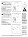
3. Locatethejam nutand lock nut on the front sideof the
stabilizerbracket.See Fig. 5-1.After looseningthejam
nut:
Tightenthe lock nutto raisethefront of the deck;
Loosenthe lock nut to lowerthefront of the deck.
WARNING
Neverattemptto
4. Retightenthe jam nut loosenedearlierwhen proper
adjustmentis achieved.
Figure 5=1
Side to Side
If the cuttingdeck appearsto be mowingunevenly,a side
to side adjustmentcan be performed.Adjustif necessary
as follows:
f
make any adjustments while the
.
engine is running,
except where specii manual.
fied in the operator's
With the tractorparkedon a firm,levelsurface,place
the deck lift leverin the top notch(highestposition)
and rotateboth bladesso that they are perpendicular
with the tractor.
2. Measurethe distancefrom the outsideof the left blade
tip to the groundand the distancefrom theoutside of
the rightblade tip to theground.Bothmeasurements
takenshouldbe equal. If they'renot, proceedto the
next step.
3. Loosen,butdo NOT remove,the hexcap screwon
the left deck hangerbracket.See Fig. 5-2.
4. Balancethe deck by usinga wrenchto turn the
adjustmentgear (foundimmediatelybehindthe hex
cap screwjust loosened)clockwise/upor counterclockwise/down.Thedeck is properlybalancedwhen
bothblade tip measurementstakenearlierare equal.
Figure 5=2
,_
5. Retightenthe hex capscrewon the left deck hanger
bracketwhenproperadjustmentis achieved.
adjustments
whileattempt
the engine
is running,
WARNING: Never
to make
any
except where specified in the operator's
manual.
Leveling the Deck
NOTE:Checkthe tractor'stire pressurebeforeperforming anydeck levelingadjustments.Referto Tires on
page24 for informationregardingtire pressure.
Front To Rear
Thefront of the cuttingdeck is supportedbya stabilizer
bar that canadjustedto levelthe deck from frontto rear.
Thefront of the deck shouldbe between1/4-inchand
3/8-inch lowerthanthe rear of the deck.Adjustif
necessaryas follows:
2O
Parking
Brake Adjustment
WARNING:Never attempt to adjust the
brakes while the engine is running. Always
disengage PTO,move shift lever into
neutral position, stop engine and remove
key to prevent unintended starting.
Adjusting
If the tractordoesnot cometo a completestop whenthe
brakepedal is completelydepressed,or if the tractor's
rearwheelscan roll with the parkingbrakeapplied,the
brakeis in need of adjustment.See an authorizedMTD
Service Dealerto haveyourbrakesproperlyadjusted.
Seat Adjustment
NOTE:For shippingreasons,seatsare eitherfastened
to the tractorseat'spivotbracketwith a plastictie, or
mountedbackwardto thepivot bracket.Ineither case,
free the seatform its shippingpositionand removethe
two hexscrews(or knobs,on modelssoequipped)from
the bottomof seat beforeproceedingwith applicable
instructions.
_
Figure 5=3
WARNING
Never attemptto
adjust the brakes while
the engineis running.
Alwaysdisengage
PTO,move shift lever
intoneutral position,
stopengine and
remove key to prevent
unintended starting.
make
sure the seatoperating
is engaged
in machine,
the seat
ARNING:Before
this
stop, stand behind the machine and pull
back on seat until fully engaged into stop.
Standard Seat
Toadjust the positionof the seat,loosenthe two hex
screwson the bottomof the seat.Slide the seatforward
or backwardas desired.Refightenthe two screws.See
Fig.5-3.
Knob Adjustment Seat (if so equipped)
Toadjust the positionof the seaton modelsso equipped,
loosenthe two knobson the bottomof theseat. See
Fig.5-4. Slide the seatforwardor backwardas desired.
Retightenthe two knobs.
Quick Adjust Seat (if so equipped)
Toadjust the positionof the seaton modelsequipped
with a seat adjustmentlever,movethe seatadjustment
lever(locatedunder theseat) to the left and slidethe
seat forwardor rearward.See Fig. 5-5. Makesureseat is
locked intopositionbeforeoperatingthe tractor.
Before operating this
machine, make sure the
Figure 5=4
seat is engaged in the
seat stop, stand behind
the machine and pull
back on seat until fully
engaged intostop.
NOTE: For shipping reasons, seats are either
fastened to the tractor
;eat's pivot bracket with
olastic tie, or mounted
backward to the pivot
bracket. In either case,
free the seat form its
shipping position and
removethe two hex
screws (or knobs, on
models so equipped)
from the bottom of seat
Figure 5=5
21
before proceeding with
applicable instructions.
4. Servicethe oil filter (if so equipped)as instructedin the
separateEngineOperator/OwnerManualpackedwith
yourunit.
Performthe abovestepsinthe oppositeorder afteroil has
finisheddraining.
5. Refillthe enginewith newmotoroil as instructed
inthe
EngineOperator/OwnerManualpackedwith your unit.
IMPORTANT:Referto the EngineOperator/Owner
Manualpackedwith yourunit for information
regardingthe
quantityand properweight of motoroil.
Tract or
Air Cleaner
Servicethe pre-cleaner,if soequipped,and cartridge/air
cleanerelementas instructedin the EngineOperator/
OwnerManualpackedwith your unit.
Spark Plug(s)
Thespark plug(s)shouldbe cleanedand thegap reset
oncea season.Sparkplug replacementis recommended
at the startof each mowingseason.Referto the Engine
Operator/OwnerManualfor correctplug type and gap
specifications.
\
WARNING
Lubrication
aBeforeperforming
ny maintenance or
repairs, disengage
PTO, move shift lever
into neutral position,
set parking brake, stop
engine and remove key
to prevent unintended
starting.
Before lubricating,
repairing, or inspecting, always disengage
PTO, move shift lever
into neutral position,
set parking brake, stop
engine and remove key
to prevent unintended
starting.
,_
_S
Single
........
Engine
Lubricatethe enginewith motoroil as instructedin the
EngineOwnerManualpackedwith yourunit.
J
Figure 6=1
Pivot Points & Linkage
Lubricateall the pivotpoints on the drivesystem,parking
brakeand lift linkageat least oncea seasonwith lightoil.
maintenance or repairs,disengagePTO,
WARNING:Before
performingany
move shift lever into neutral position, set
parking brake, stop engine and remove
key to prevent unintended starting.
_
Rear Wheels
The rearwheelsshouldbe removedfrom the axles once
a season.Lubricatethe axles and the rimswell with an
all-purposegreasebeforere-installingthem.
Engine
Refer to the Engine Operator/Owner Manualfor
enginemaintenance instructions.
Checkengine oil level beforeeachuseas instructed
inthe EngineOperator/OwnerManualpackedwith your
unit. Follow the instructionscarefully.
Changing
Front Axles
Eachend of the tractor'sfront pivot bar may be equipped
with a greasefitting. Lubricatewith a greasegun after
every25 hoursof tractoroperation.
Engine Oil
Fordrainingoil from the engine'scrankcaseof select
modeltractors,a plasticoil drain sleeveis packedwith
this Operator'sManual.Todrain the oil, proceedas
follows:
.
inspecting, always
disengage PTO,move
WARNING:
Before lubricating,
repairing, or
shift lever into neutral position, set parking
brake, stop engine and remove key to
prevent unintended starting.
Unscrewthe oil fill capand removethe dipstickfrom
theoil fill tube.
2. Snapthe small end of oil drain sleeveontothe oil
sump.See Fig.6-1.
3. Removedrain plug and drain oil intoa suitable
containerwith a capacityof no less than64 oz.
22
Cleaning
the Engine And Deck
Anyfuel or oil spilledon the machineshouldbe wiped
off promptly.DoNOT allowdebristo accumulatearound
thecoolingfins of the engineor on any otherpart of the
machine.
iMPORTANT:The useof a pressurewasherto clean
yourtractoris NOT recommended.It may causedamage
to electricalcomponents,spindles,pulleys,bearingsor
theengine.
Your LaWn
Deck Wash System TM
A hexplug can be foundon yourtractor'sdeck surface.
See Fig. 6-2.
i
This plug canbe replacedwith a waterport to be usedas
part of a separately-available
deck wash system.
Use the DeckWashSystemTM to rinsegrassclippings
fromthe deck'sundersideand preventthe buildupof
corrosivechemicals.
HexPlug
k,,,,
Figure 6=2
NOTE:Referto page 28 for informationregardingthis
and otherseparately-available
attachments& accessoriesfor yourtractor.
Cutting
NOTE: Models
Deck Removal
equippedwith a 38-inch
deck have one deck
NOTE:Modelsequippedwith a 38-inchdeck have
one deck idler pulley.Modelsequippedwith a 42- and
46-inchdeck havetwo deck idler pulleys.
idler pulley. Models
)quipped with a 42- and
46-inch deck have two
To removethecuttingdeck, proceedas follows:
1. Placethe PTO(Blade Engage)leverin the disengaged(OFF) positionandengagethe parkingbrake.
deck idler pulleys.
2. Lowerthe deck by movingthedeck lift leverintothe
bottomnotchon the rightfender.
3. Removethe beltfrom aroundthetractor'sengine
pulleyand idler pulley(s).Referto Changingthe Deck
Belton page26 for detailedinstructions.
4. Lookingat the cuttingdeck from theleft sideof the
tractor,locatethe hair pin clip that securesthe deck
supportrod on the rear left sideof the deck.
See Fig. 6-3.
Figure 6=3
5. Removethe hairpin clipthat securesthedeck
supportrod, and carefullyremovethe deck support
fromthe deck lift arm.
F
6. Repeattheabovestepson thetractor'srightside.
7. Movethe deck lift leverintothe top notchon the right
fenderto raisethe deck lift arms up and out of the
way.
8. Carefullyremovethe PTOcablefrom the rearof
thecutting deck by removingthe hair pinclip which
securesit. Removethe springfrom the deck idler
bracket.See Fig.6-4.
9. Gentlyslidethe cuttingdeck towardthe frontof the
tractorallowingthe hookson the deck to release
themselvesfromthe deck stabilizerrod.
10.Gentlyslidethe cuttingdeck (from the rightside)out
from underneaththe tractor.
Figure 6-4
23
Jump Starting
Tires
_
inflation
pressure shown
sidewall
ARNING:Never
exceedon
thethe
maximum
of tire.
battery,
follow
these instructions
to prevent
ARNING:
Whenremoving
or installing
the
the screwdriver from shorting against the
frame.
_
The recommendedoperatingtire pressureis:
Ma| !ltal
n !ng
|_iAlllt
,, ,_,,,,_ _ ,,,,,_,_vv,, •
Tractor
IMPORTANT:Neverjump yourtractor'sdead batterywith
the batteryof a runningvehicle.
• Approximately10 psifor the rear tires
• Approximately14psi for the fronttires
1. Connectend of one jumpercableto the positive
terminalof the good battery,thenthe otherend to the
positiveterminalof the dead battery.
MPORTANTI aefertothetresdewa forexactt re
manufacturersrecommendedor maximumpsi. Do not
overinflate.Uneventirepressurecouldcausethe cutting
deck to mow unevenly.
Battery
2. Connectthe otherjumpercable to the negative
terminalof the good battery,thento the frame of the
unit with the dead battery.
The batteryis sealedand is maintenance-free.Acid
levelscannotbe checked.
3. Start the tractor as instructedon page 15.
• Alwayskeepthe batterycablesand terminalsclean
and freeof corrosivebuild-up.
_
• Aftercleaningthe batteryand terminals,apply a light
coat of petroleumjelly or greaseto bothterminals.
WARNING
Never exceed the
maximum inflation
pressure shown on
the sidewall of the
tire.
Batteries give off an
explosive gas while
charging. Charge
battery in a well
ventilated area and
keep away from an
open flame or pilot
light as on a water
heater, space heater,
furnace, clothes
dryer or other gas
appliances.
Always use a fuse
with the same
amperage capacity
for replacement.
Cleaning
Cleanthe batteryby removingit fromthe tractorand
washingwith a bakingsodaand water solution.If necessary,scrapethe batteryterminalswith a wire brushto
removedeposits.Coatterminalsand exposedwiringwith
greaseor petroleumjelly to preventcorrosion.
• Alwayskeepthe rubberboot positionedoverthe
positiveterminalto preventshorting.
IMPORTANT:If removingthe batteryfor anyreason,
disconnectthe NEGATIVE(Black)wire fromit'sterminal
first, followedby the POSITIVE(Red)wire. When
re-installingthe battery,alwaysconnectthe POSITIVE
(Red)wire itsterminalfirst, followedby the NEGATIVE
(Black)wire. Be certain that thewires are connectedto
thecorrectterminals;reversingthemcouldchangethe
polarityand result in damageto your engine'salternating system.
Charging
Battery Failures
Somecommoncausesfor batteryfailureare:
• incorrectinitialactivation • undercharging
• overcharging
• corrodedconnections
• freezing
These failures are NOTcovered by your tractor's
warranty.
IMPORTANT:Whenchargingyour tractor'sbattery,use
onlya chargerdesignedfor 12Vlead-acidbatteries.
Readyourbatterycharger'sOwner'sManualpriorto
chargingyourtractor'sbattery.Alwaysfollow itsinstructionsand heeditswarnings.
Fuse
One 20 AMPfuse is installedin yourtractor'swiring harness to protectthe tractor'selectricalsystemfrom damage
causedby excessiveamperage.
If the electricalsystemdoes notfunction,or yourtractor's
enginewill notcrank,first checkto be certainthat the fuse
has notblown. It can be foundunder thehood mounted
behindthe dashpanelon the rightside.
If yourtractorhasnot been put intousefor an extended
periodof time,chargethe batteryas follows:
• Setyour batterychargerto delivera maximumof 10
amperes.If your batterychargeris automatic,charge
the batteryuntilthe chargerindicatesthat chargingis
complete.
_
NOTE:If the chargeris notautomatic,chargefor no
fewerthaneight hours.
_
could
causeFailure
sparking,
andthis
thegas
in either
ARNING:
to use
procedure
battery could explode.
gas
while charging. Charge
in a
ARNING:Batteries
give offbattery
an explosive
well ventilated area and keep away from
an open flame or pilot light as on a water
heater, space heater, furnace, clothes
dryer or other gas appliances.
24
WARNING:Always
use a fuse
with the
same amperage capacity
for replacement.
f
Cutting Blades
,_
off, remove ignition
the
WARNING:
Be sure key,disconnect
to shut the engine
spark plug wire(s) and ground against
the engine to prevent unintended starting
before removing the cutting blade(s) for
sharpening or replacement. Protect your
hands by using heavy gloves or a rag to
grasp the cutting blade.
Maintaining
WARNING: Periodically inspect the blade
spindles for cracks or damage, especially
if you strike a foreign object. Replace
immediately if damaged.
The bladesmay be removedas follows.
1. Removethe deck from beneaththe tractor,(referto
CuttingDeckRemovalon page23) thengently flip
thedeck overto expose its underside•
Figure 6-5
2. Placea blockof wood betweenthe centerdeck housing baffle and the cuttingbladeto act as a stabilizer.
See Fig. 6-5.
f
WARNING
3. Removethe hexflangenutthat securesthe bladeto
the spindleassembly.See Fig.6-5.
4. Toproperlysharpenthe cuttingblades,removeequal
amountsof metalfrom bothends of the bladesalong
thecutting edges,parallelto the trailingedge,at a
250to 300angle.
IMPORTANT:If the cuttingedgeof the blade hasalready
been sharpenedto within 1 5/8" from theedge,or if any
metal separationis present,replacethe bladeswith new
ones. See Fig.6-6.
\\\\
• It is importantthat eachcuttingblade edge be ground
equallyto maintainproperblade balance•
• A poorlybalancedbladewill causeexcessive
vibrationand maycausedamageto thetractorand
result in personalinjury.The bladecan be testedby
balancingit on a roundshaftscrewdriver.Grind metal
fromthe heavysideuntil it balancesevenly.
• Whenreplacingtheblade,be sureto installthe blade
with the sideof the blade marked"Bottom" (or with
a part numberstampedin it) facingthe groundwhen
the moweris in the operatingposition.
Idlerpulleys
IMPORTANT:Usea torquewrenchto tighten the blade
spindlehexflangenutto between70 foot-poundsand 90
foot-pounds.
Idler pulleynuts
Figure 6-7
25
Be sure to shut the
engine off, remove
ignition key, disconnect the spark plug
wire(s) and ground
against the engine to
prevent unintended
irting before removthe cutting blade(s)
for sharpening or
replacement. Protect
your hands by using
heavy gloves or a rag
to grasp the cutting
blade.
Periodically inspect
the blade spindles for
cracks or damage,
especially ifyou strike
a foreign object.
_laceimmediately if
damaged.
Changing
the Deck Belt
_1=
WARNING:Be sure to shut the engine
off,removeignition key,disconnect the
spark plug wire(s) and ground against
the engine to prevent unintended starting
before removing the belt.
5. Removethedeck belt fromaroundall pulleys,including
the deck idler pulley.
All belton yourtractorare subjectto wearand shouldbe
replacedif any signsof wearare present.
6. Routethe newbelt as shownin and Fig.6-8, 6-9 or
6-10.
IMPORTANT:TheV-beltfoundon yourtractorare
speciallydesignedto engageand disengagesafely.A
substitute(non-OEM)V-beltcan be dangerousby not
disengagingcompletely.Fora properworkingmachine,
usefactory approvedbelts.
7. Remountthe beltguardsremovedearlier.
Changing
Be sure to shut the
engine off, remove
ignition key, d isconnect the spark plug
wire(s) and ground
against the engine to
prevent unintended
starting before remov=
ing the belt.
Avoid the possibility of
a pinching injury. Do
not place your fingers
on the idler spring or
between the belt and a
pulley while removing
the belt.
the Lower Deck Belt (46" Decks)
NOTE:Severalcomponentsmustbe removedin orderto
changethe tractor'slowerdeck belt. Seean authorized
MTDService Dealerto haveyourlowerdrivebelt replaced
or phoneCustomerSupportas instructedon page2 for
information
on orderinga ServiceManual.
Tochangeor replacethe deck belt on yourtractor,
proceedas follows:
WARNING
ing
injury. Do not place
your fingers on
the
ARNING:Avoid
the possibilityofa
pinchidler spring or between the belt and a pulley
while removing the belt.
1. Lowerthe deck by movingthe deck lift leverintothe
bottomnotchon the rightfender.
Changing
2. Removethe beltguardsby removingthe self-tapping
screwsthat fastenthem to the deck.
NOTE:Severalcomponentsmustbe removedand special
tools (i.e.air/impactwrench)in orderto changethe
tractor'sdrive belt. Seean authorizedMTDServiceDealer
Removethe beltkeeperrodfrom aroundthe engine
pulley.
.
4. On the 42-inchdeck only, loosenbut do not remove,
the idler pulleynuts.This will enablethe belt to be
easily removedfrom the idler pulleys.See Fig. 6-7 on
the previouspage.
the Transmission
Drive Belt
to haveyourdrivebelt replacedor phoneCustomerSupportas instructedon page 2 for informationon orderinga
ServiceManual.
f
38-Inch Deck
Engine Pulley
\
Idler Bracket
©
o
b
Deck Idler Pulley
Figure 6=8
26
42-Inch Deck
_
Engine Pulxley
Idler Bracket
\
Tractor
©
Deck Idler Pulleys
..
.j
Figure
6=9
46-inch Deck_
0
©
Belt Cover
Idler Pulleys
J
Figure
27
6=10
Cleanand lubricatethe tractoras instructed
in Section
6: MAiNTAiNiNGYOUR LAWNTRACTORon page 19
of this manualbeforestoringfor an extendedperiod.
,_
Followthe instructions
in the Service, Storage &
Specifications sectionof the EngineOperator/Owner
Manualfor properenginecare priorto storingyourtractor.
container outdoors,awayfroman
WARNING:Drainfuel
only into an open
approved _
flame.Allow engine to cool Extinguish
cigarettes,cigars,pipes, and other sources
of ignition prior to draining fuel.
Attachments
container
indoors
wherethe
there
is an open
ARNING:
Never store
machine
or fuel
flame, spark or pilot light such as on water
heater, furnace, clothes dryer or other gas
appliance.
& Accessories
Attachments Thefollowingattachmentsand accessoriesare compatiblefor ModelSeries700 LawnTractors.See the retailer
from whichyou purchasedyourtractor,an authorizedMTDServiceDealeror phone(800) 800-7310for information
regardingpriceand availability.
NOTE:ModelSeries700 LawnTractorsare NOTdesignedfor usewith any type of ground-engagingattachments
(e.g.tiller or plow). Useof this type of equipmentWILL voidthe tractor'swarranty.
WARNING
i Drain fuel only into an
approvedcontainer
outdoors,away
froman openflame.
Allow engine to cool.
Extinguishcigarettes,
cigars, pipes, and
other sources of
ignitionpriorto
drainingfuel.
0EM-190-032
42-inchTwo-stageSnowThrower
0EM-190-116
38/42-inchDeck MulchKit
0EM-190-118
46-inch DeckMulchKit
0EM-190-180
Twin BaggerGrassCollector(for 38/42-inchDecks)
0EM-190-182
Twin BaggerGrassCollector(for 46-inchDecks)
0EM-190-183
DeckWheel Kit
0EM-190-215
RearWheelWeightKit
0EM-190-607"
DeluxeTractorSunshade
0EM-190-658
Tire Chains,20 x 8 Tires
0EM-190-672
GrilleGuard(mountson front of tractor)
0EM-190-833
42-inchFrontDozerBlade
490-900-0025
DeckWash Kit
* Notcompatiblewith tractorsequippedwith a Grass Collector
i Neverstorethe
imachine orfuel
icontainerindoors
wherethere isan
openflame, sparkor
ipilotlightsuchas on
_waterheater,furnace,
iclothesdryeror
iothergas appliance.
28
ROTATING BLADES CAUSE
SERIOUS INJURY OR DEATH
• DONOTMOWWHENCHILDRENOR
OTHERSAREAROUND
• NEVERCARRYCHILDRENEVENWITH
BLADE(S)OFF.
• LOOKDOWNANDBEHINDBEFORE
ANDWHILEBACKING.
WARNING
This symbol points
out importantsafety
instructionswhich, if
not followed,could
endangerthe personal
safety and/or property
of yourselfand others.
Readand follow all
instructionsin this
manual beforeattemptingto operate
this machine. Failure
to complywith these
instructionsmay result
in personalinjury.When
you see this symbol.
KEEP
SAFETY
HEED ITS WARNING!
Your Responsibility
Restrict the use
of this power machine
to persons who read,
understand
and follow the warnings
and instructions
in this manual
and on the machine.
29
Pro bl e m
Ca use
Eng ne fa s to start
1. PTOengaged
Remedy
1 PlacePTOknob (or lever)in
disengaged(OFF)postion.
Trou
Shootin
Engineruns erratic
For repairs
beyond the minor
adjustments listed
here, contact an
i authorized service
dealer.
2. Sparkplugwire(s) disconnected.
3. Fue tank emptyor stae fue .
2. Connectwire(s) to spark plug(s).
3. F tank w th c can fresh gaso ne
4 Chokenot act vated
•
"
4. Pullout the CHOKEcontrol (if so
equipped)or placethe throttle
control in CHOKEposition.
5. Faultysparkplug.
5. Clean,adjust gap,or replace.
6. Blockedfuel hne.
6. Cleanfuel I ne or replacefuelfilter,
7. Engineflooded,
if so equipped.
7. Crankenginewith throttle in FAST
8 Parkingbrakenotengaged.
position.
8. Engageparkingbrake.
9. Throttlecontrol levernotin correct
startingposition,
9. Placethrottleleverto FAST
position.
1. Unit runningwith CHOKEapplied.
1. PushCHOKEcontrol(if so
equipped)in, or movethe throttle
controlout of the CHOKEposition.
2. Sparkplug wire(s) loose.
2. Connectand tightenspark
plug wire(s).
3. Blockedfuelline or stale fuel.
_
3. Cleanfuel line;fill tank with clean,
fresh (less than30 daysold)
gasoline.Replacefuel filter,if so
equipped.
4. Ventin gas cap plugged.
4. Clearvent or replaceif damaged.
5. Wateror dirt in fuel system.
5. Drainfuel tank. Refillwith
fresh fuel.
6. Dirty air cleaner.
6. Replaceair cleanercartridge/element or clean pro-cleaner,if so
equipped.
J
3O
Problem
Cause
ne overheats
Remedy
1} Engineoil levelIowl
21
Fill crankcasewith properoil.
Air flow restricted.
2. C!eangrassclippingsand debrs
from aroundtheengineScoo!ing
fins and blowerhousing.
Enginehesitates at
high RPM
1. Sparkplug(s)gap tooclose.
des poor
i sPark p!ug(s)fou ed faulty or
too Wide;
1. Removesparkplug(s)and reset
U
the gap.
Replace Spaikp!ug(S):Set plug(s)
gapl
2 Dirtyair c!eaner.
2 Replaceair cleanercartridgeiele_
mentor cleanpre:cleaner,if S0
equipped.
1. Cuttingblade looseor unbalanced.
1. Tightenbladeand spindle.
ii
Excessive
Vibration
Balanceblade.
2. Damagedor bentcuttingblade.
Mower wili not
mu ch grass
(mode1s equipped
with
a
mu/ il'kJt _
c
EnginesPeedtoo Iowl
Wet giass
2. Replaceblade.
li
PlaCethrottle Controlin FAST
Forrepairs
(rabbit)p0siti°n,
....
3 Excessivelyhigh grass:
........................
Uneven cut
ii
beyond the minor
2wet;.
Do not mowwhengrass is
adjustments
listed
watunt atertocut
_ ;
:_ . .
here,
contact
an
_. Ivlowonce al a nigh cumnghe!gnu,
rthorized
service
then mow againat desiredheight
dealer.
oimake a nar[owercuttingpathI
4.1Dullblade:
&sharpen or replaceblade:
1. Decknotbalancedproperly.
2. Dullblade,
1. Performside-to-sidedeck adjustment.
3. Uneventire pressure.
2. Sharpenor replaceblade.
3. Checktire pressurein all four
tires.
_iii_i_
i
ii
iii
i
i
_ ii_i
_
_ ii_
_
i ii_
_ i_ii ii
i
ii}
I
i
ii _
i
ii i!_ii_ii_i_ii_!i
I i iiiiiiii_iii
31
i
i
I
_FACTORY
PARTS
NOTE:Phone(800) 800-7310to order replacementpartsor a completePartsManual(have
your fullmodelnumberand serialnumberready).PartsManualdownloadsare also available
free of chargeat www.mtdproducts.com.
WARNING
a safety feature
isnotfunctioning
DriveBelt (Transmission)
754-04001A
DriveBelt (MowingDeck)38" Deck
754-04062
DriveBelt (MowingDeck)42" Deck
754-04060B
UpperDriveBelt (MowingDeck)46" Deck
754-04142
LowerDriveBelt(MowingDeck)46" Deck
754-0349
DeckBlades(38"Deck- two each)
742-0610A
DeckBlade(42" Deck)
742-0616A
DeckBlade(46" Deck)Center Blade(one ea.)
742-0612A
DeckBlade(46" Deck)Outer Blade(two ea.)
742-0611A
DeckSpindle(38" Deck)
618-04197
DeckSpindle(42"Deck)
618-04456
DeckSpindle(46"Deck)DoublePulley(one ea.)
618-04134B
DeckSpindle(46"Deck)(two each)
618-0240A
DeckWheels
734-0973
Battery(13 hp Tecumseh)
725-1704A
Battery(15.5hp Briggs& Stratton)
725-1737A
and/or illustrated in
this manual may not
appliCable to al models:
MTD LLC reservesthe
Tire(Front) 15x 6 x 6 RoundShoulder
734-0864
Tire(Front) 15x 6 x 6 SquareShoulder
734-1731
Tire(Rear)20 x 8 x 8 RoundShoulder
734-1596
Tire(Rear)20 x 8 x 8 SquareShoulder
734-1730
rightto ChangeprOduCt
specifications designs
and equipmentwithout
notiCeand Without
incurring obligation.
HubCap
731-0484A
FuelTankCap
951-3111
ChokeControl/Cable(TwinCylinderEngines)
746-1085A
ThrottleControl/Cable(SingleCylinderEngines)
746-04258
DischargeChuteAssembly
931-1032B
properly, do not use
the tractor.Contact
your authorized MTD
servicedealeror call
8oo
)800,73 oi
This Operators
ManUalCoversa range
of product specifiCations
for Various models:
CharaCteristicsand
featuresdiscussed
_
ARNING:If
a safety
featureis
not functioning
do not use the tractor. Contact
your
authorized
MTDservice
dealer
or call (800)properly,
800-7310.
32
NOTES
Use this page to make notes and write down important information.
33
CALIFORNIA EMISSION CONTROL WARRANTY STATEMENT
YOUR WARRANTY RIGHTS AND OBLIGATIONS
The CaliforniaAir ResourcesBoardandMTDConsumerGroupInc are pleasedto explainthe evaporativeemissioncontrolsystemwarrantyon your 2007lawn
mower.In California,new lawnmowermust be designed,builtand equippedto meet the State'sstringentanti-smogstandards.MTDConsumerGroupInc must
warrantthe EECSon yourlawn mowerfor the periodof time listedbelow providedthere has beenno abuse,neglector impropermaintenanceof your lawnmower.
Your EECSmay includeparts such as the carburetor,fuel-injectionsystem,the ignitionsystem,catalyticconverter,fuel tanks,fuel lines,fuel caps, valves,
canisters,filters,vapor hoses,clamps,connectors,and otherassociatedemission-relatedcomponents.
Where a warrantable condition exists, MTDConsumer Group Inc will repair your lawn mower at no cost to you includingdiagnosis, parts and labor.
MANUFACTURER'S
WARRANTY COVERAGE:
This evaporativeemissioncontrol systemis warrantedfor two years.If any evaporativeemission-relatedpart on yourequipmentis defective,the partwill be
repairedor replacedby MTDConsumerGroupInc.
OWNER'S WARRANTY RESPONSIBILITIES:
Asthe lawn mowerowner,you are responsiblefor performanceof the requiredmaintenancelistedin yourowner'smanual. MTDConsumerGroupIncrecommendsthat you retain all receiptscoveringmaintenanceon your lawnmower,but MTDConsumerGroup Inccannot denywarrantysolelyforthe lack of receipts.
Asthe lawn mowerowner,you shouldhoweverbe awarethat MTDConsumerGroupInc maydeny you warrantycoverageif your lawnmoweror a part has failed
dueto abuse,neglect, or impropermaintenanceor unapprovedmodifications.
Youare responsiblefor presentingyourlawn mowerto MTDConsumerGroupInc's distributioncenteror servicecenteras soonas the problemexists.The
warrantyrepairsshouldbe completedin a reasonableamountof time, not to exceed30 days. If you havea questionregardingyour warrantycoverage,you should
contactthe MTDConsumerGroupIncService Departmentat 1-800-800-7310.
GENERAL
EMISSIONS WARRANTY
COVERAGE:
MTDConsumerGroupIncwarrantsto the ultimatepurchaserand eachsubsequentpurchaserthat the lawnmower is: Designed,built andequippedso as to
conformwithall applicableregulations;andfree from defectsin materialsand workmanshipthat causethe failure of a warrantedpart to be identicalin all material
respectsto that part as describedin MTDConsumerGroupInc's applicationfor certification.
The warrantyperiodbeginson the date the lawnmoweris deliveredto an ultimatepurchaseror first placed into service.The warrantyperiodis two years.
Subjectto certain conditionsand exclusionsas statedbelow,the warrantyon emission-relatedparts is as follows:
1. Any warrantedpart that is not scheduledfor replacementas requiredmaintenanceinthe writteninstructionssupplied, is warrantedfor the warranty period
statedabove. Ifthe part fails duringthe periodof warrantycoverage,the part will be repairedor replacedby MTDConsumerGroupInc accordingto subsection
(4) below. Anysuch part repairedor replacedunderwarrantywill be warrantedfor the remainderof the period.
2. Any warrantedpart that is scheduledonly for regularinspection inthe writteninstructionssupplied is warrantedfor the warranty periodstated above.Any such
part repairedor replacedunderwarrantywill be warrantedfor the remainingwarrantyperiod.
3. Any warrantedpart that is scheduledfor replacementas requiredmaintenancein the written instructionssuppliedis warrantedforthe periodof time beforethe
first scheduledreplacementdatefor that part. If the partfails beforethe first scheduledreplacement,the part will be repairedor replacedby MTDConsumer
GroupInc accordingto subsection(4) below.Any such part repairedor replacedunderwarrantywill be warrantedforthe remainderof the periodpriorto the
first scheduledreplacementpointfor the part.
4. Repairor replacementof any warrantedpart underthe warrantyprovisionshereinmustbe performedat a warrantystationat no chargeto the owner.
5. Notwithstandingthe provisionsherein,warrantyservicesor repairswill be providedat all of our distributioncentersthat arefranchisedto servicethe subject
enginesor equipment.
6. The lawnmowerowner will not be chargedfor diagnosticlaborthat is directlyassociatedwithdiagnosisof a defective,emission-relatedwarrantedpart,
providedthat such diagnosticwork is performedat a warrantystation.
7. MTDConsumerGroupInc is liablefor damagesto otherengine or equipmentcomponentsproximatelycausedby a failure underwarrantyof any warranted
part.
8. Throughoutthe lawnmowerwarrantyperiodstated above,MTDConsumerGroupIncwill maintaina supplyof warrantedparts sufficientto meetthe expected
demandfor such parts.
9. Any replacementpart may be usedinthe performanceof any warrantymaintenanceor repairsand mustbe providedwithoutchargeto the owner.Suchuse will
not reducethe warrantyobligationsof MTDConsumerGroupInc.
10. Add-onor modifiedpartsthat are not exemptedbythe Air ResourcesBoardmay not be used.The use of any non-exemptedadd-on or modifiedparts bythe
ultimatepurchaserwill be groundsfor disallowinga warrantyclaims. MTDConsumerGroup Incwill not be liableto warrantfailuresof warrantedparts caused
bythe use of a non-exemptedadd-onor modifiedpart.
WARRANTED
PARTS:
The repairor replacementof any warrantedpart otherwiseeligiblefor warrantycoveragemay be excludedfrom such warrantycoverageif MTDConsumerGroup
Inc demonstratesthat the lawnmowerhas been abused,neglected,or improperlymaintained,andthat such abuse, neglect,or impropermaintenancewasthe
directcauseof the needfor repairor replacementof the part. That notwithstanding,any adjustmentof a componentthathas a factory installed,and properly
operating,adjustmentlimiting device is still eligiblefor warrantycoverage.Thefollowing emissionwarrantyparts list arecovered: FuelLine,Fuel Line Clamps
MANUFACTURER'S
LiMiTED WARRANTY
The limitedwarrantyset forth belowisgivenby MTDLLCwith respect
to newmerchandisepurchasedand usedin the UnitedStates,its
possessionsand territories.
"MTD"warrantsthis productagainstdefectsin materialand workmanshipfor a periodof two (2) years commencingon the date of original
purchaseand will, at its option,repairor replace,freeof charge,any
part foundto be defectiveinmaterialsor workmanship.This limitedwarranty shallonlyapply if this product hasbeen operatedand maintained
inaccordancewith the Operator'sManualfurnishedwith the product,
and has notbeen subjectto misuse,abuse,commercialuse, neglect,
accident,impropermaintenance,alteration,vandalism,theft, fire, water,
or damagebecauseof otherperil or naturaldisaster.Damageresulting
fromthe installationor useof any part, accessoryor attachmentnot
approvedby MTDfor use with the product(s)coveredbythis manual
willvoid yourwarrantyas to any resultingdamage.
Normalwearparts are warrantedto be free fromdefects in materialand
workmanshipfor a periodof thirty (30) days fromthe dateof purchase.
Normalwearparts include,butare notlimitedto itemssuch as: batteries,belts,blades,blade adapters,grass bags, riderdeck wheels,seats,
snowthrowerskid shoes,shaveplates,auger spiralrubberand tires.
HOW TO OBTAIN SERVICE: Warranty service is available, WITH
PROOF OF PURCHASE, through your local authorized service
dealer. To locate the dealer in your area, check your Yellow Pages,
or contact MTD LLC at RO. Box 361131,Cleveland, Ohio 441360019, or call 1-800-800-7310 or 1-330-220-4683 or log on to our
Web site at www.mtdproducts.com.
This limitedwarrantydoesnot providecoverageinthe followingcases:
a. Theengineor componentparts thereof.These itemsmaycarry a
separatemanufacturer'swarranty.Referto applicablemanufacturer's
warrantyfor termsand conditions.
b. Log splitterpumps,valves,and cylindershavea separateone year
warranty.
c. Routinemaintenanceitemssuch as lubricants,filters, blade
sharpening,tune-ups,brakeadjustments,clutchadjustments,deck
adjustments,and normaldeteriorationof the exteriorfinish due to
useor exposure.
FOR
e. MTDdoesnot extendanywarrantyfor productssoldor exported
outsideof the UnitedStates,its possessionsand territories,except
those soldthroughMTD'sauthorizedchannelsof export distribution.
f. Replacementparts that are notgenuine MTDparts.
g. Transportationchargesand servicecalls.
No impliedwarranty,includingany impliedwarranty of merchantabilityof fitness for a particular purpose,applies after the
applicable periodof express written warranty above as to the
parts as identified.No otherexpresswarranty, whetherwrittenor
oral, except as mentioned above, givenby any personor entity,
includinga dealeror retailer, with respect to any product,shall
bind MTD.Duringthe periodof the warranty,the exclusiveremedy
is repairor replacementof the productas set forth above.
The provisionsas set forth in this warrantyprovidethe sole and
exclusiveremedy arising from the sale. MTDshallnot be liable
for incidentalor consequentialloss or damage including,without
limitation, expensesincurredfor substituteor replacementlawn
careservicesor for rentalexpensesto temporarily replacea
warranted product.
Somestatesdo notallowthe exclusionor limitationof incidentalor
consequentialdamages,or limitationson howlong an impliedwarranty
lasts, sothe aboveexclusionsor limitationsmaynot applyto you.
In no event shallrecoveryof any kindbe greaterthanthe amountof the
purchasepriceof the productsold.Alterationof safety features of
the productshallvoid this warranty. Youassumethe risk and liability
for loss,damage,or injuryto you and yourpropertyand/orto others and
theirpropertyarisingout of the misuseor inabilityto usethe product.
This limitedwarrantyshallnot extendto anyoneotherthan theoriginal
purchaseror to the personfor whomitwas purchasedas a gift.
HOWSTATELAWRELATESTOTHIS WARRANTY: This limited
warrantygivesyou specificlegal rights,and youmay alsohaveother
rightswhich vary from stateto state.
IMPORTANT:OwnermustpresentOriginal Proofof Purchaseto obtain
warrantycoverage.
d. Servicecompletedby someoneotherthanan authorizedservice
dealer.
IVITD LLC, P.O. BOX 361131 CLEVELAND, OHiO 44136-0019;
GDOO-lO0015 REV.A
Phone: 1=800=800-7310, 1-330=220-4683
Seguridad • Montaje • Funcionamiento
A
AL
• Ajuste • Mantenimiento
L
• Soluci6n de problemas • Garantia
P
O
A
Shift=On=The-Go'" Tractor corta c sped -- Modelos 760-779
IMPORTANTE
LEA CON ATENCION
LAS REGLAS DE SEGURIDADY
LAS INSTRUCCIONES
PONER LA UNIDAD EN FUNCIONAIVllENTO
ANTES
DE
Advertencia: Estaunidadest_ equipadacon un motorde cornbusti6ninternoy no debe ser utilizadaen o cercade un terrenoagreste
cubiertopor bosque,rnalezaso hierbaexceptoque el sisternade escapedel motorest_ equipadocon un arnortiguadorde chispasque curnpla
con las leyeslocaleso estatalescorrespondientes(en caso de existiO.Si se utiliza un arnortiguadorde chispasel operadorIodebe rnantener
en condicionesde usoadecuadas.En el Estadode California las rnedidasanteriorrnenternencionadassonexigidaspor ley(Articulo4442 del
C6digode RecursosPOblicosde California).Es posibleque existanleyessirnilaresen otros estados.Las leyesfederalesse aplicanen territorios
federales.Puedeconseguirel arnortiguadorde chispasparael silenciadora travesde su distribuidorde mantenirniento
de rnotoresautorizadorn_s
cercanoo poni_ndoseen contactoconel departarnentode servicios,RO. Box361131Cleveland,Ohio 44136-0019.
IMPRESOEN ESTADOS
UNIDOSDEAME_RICA
MTD LLC, P.O. BOX 361131 CLEVELAND,
OHIO 44136-0019
FORMULARIONO769-02703
11/1/2006
Este Manual del Operador es una parte importante de su nuevo tractor corta c_sped.
Lo ayudar_ a montar, preparar y mantener
la unidad para obtener los mejores resultados.
Pot favor, lea y comprenda el contenido del manual.
Indice
Indicador de pendiente ......................................
3
Medidas importantes de seguridad .................. 4
Montaje del tractor corta cesped ...................... 8
Funcionamiento
del tractor corta cesped ...... 12
Ajuste su tractor corta cesped ........................
20
Mantenimiento
del tractor corta c_sped ........ 22
AImacenamiento
fuera de temporada/
Aditamentos ......................................................
28
Etiquetas de seguridad ....................................
Soluci6n de problemas ....................................
Garantia .............................................................
29
30
36
B squecla y registro de n mero de modelo
ANTES DE COMENZAREL MONTAJEDEL EQUIPO NUEVO,
por favor encuentre la placa de modelo del equipo y copb la
informaci6n en la placa de modelo de muestra suministrada,
del lado derecho. Puede Iocalizar la placa de modelo mirando
debajo del asbnto.
Esta informaci6nes necesaria para tener acceso al sitio web del
fabricante y/o para obtener asistencia a tra%s del Departamento
de atenci6n al cliente o de un distribuidor de servicios de
mantenimientoautorizado.
f
Model Number
Serial
Number
MTD LLC
P.O.
BOX
361131
CLEVELAND, OH 44136
330-220-4683
D
www.mtdproducts.com
800-800-731
Oy
Asistencia al Cliente
Pot favor
NO devuelva
la unidad al minorista
a trav_s del cual la compr6
contacto con Atenci6n a clientes.
sin antes ponerse
en
En caso de tener problemas para montar este producto o de tener dudas con respecto a los controles, funcionamiento o
mantenimientodel mismo, puede solicitar la ayuda de expertos. Elija entre las opciones que se presentan a continuaci6n:
1. Visite www.mtdproducts.com.
2. Comuniquese por telefono con un representante de asistencia al cliente al 1 (800) 800-7310.
3. El fabdcante del motor es el responsable de todas las cuestiones relacionadascon el rendimiento,la potencia de salida,
las especificaciones,la garantia y el servicio de mantenimiento.Por favor consulte el Manual del propietario/operador del
fabricante del motor, que se entrega pot separado con su unidad.
2
0
(D
Mire y mantenga
(D
este nivel con un arbol vertical...
0
(D
o la esquina de un edificio...
0
t'--
|_
GO
(D
o una cerca
I
I
I
I
0
o3
(:D
GO
o5
de 15.0
O9
|
E
O.O
,_
t'_
225
O
O
-'O
e_
O
O
O
O
E
O
N
C
"r225
o
O
o
Z
15°
ADVERTENClA: El escape del motor de este producto, algunos de sus
componentesy algunos componentes del vehiculo contienen o liberansustancias
quimicas que el estado de Californiaconsidera que pueden producirc_.ncer,
defectos de nacimientou otros problemas reproductivos.
PELIGRO: Esta m_.quinafue construida para set operada de acuerdo con las reglas de seguridad
contenidas en este manual. AI igual que con cualquier tipo de equipo motorizado, un descuido o
error por parte del operador puede producir lesiones graves. Esta maquina es capaz de amputar
manos y pies y de arrojar objetoscon gran fuerza. De no respetar las instrucciones de seguridad
siguientesse pueden producir lesiones graveso la muerte.
Medidas
N i Sos
ADVERTENCIA
i ¸: /: ::/:
::
La presenciadeeste
s[mbolo indica que se
trata de instrucciones
i
importantes de
seguridad que debe
respetar para ev tar
poner en riesgosu
seguridad personaly!o
materialy la de otras
personasl Lea y siga
todas as instrucciones
en este manual antes
de iniciar la operac_on
de esta maquina; En
caso deno seguir estas
instrucciones podr[a
provocar lesiones
personalesl Cuandoyea
estesimbolo:
LAS ADVERTENClAS
Su
a. utilice s61orecipientesparagasolina
autorizados.
b. NuncaIlenelos recipientesen el interiorde
un vehiculoo cami6no cajade remolquecon
recubrimientospl_sticos.Siemprecoloquelos
recipientesen el pisoy lejosdel vehiculoantes
de Ilenarlos.
1. Puedenocurriraccidentestr&gicossi el operadorno
est,. atentoa la presenciade ni_os.Por Iogeneral,los
ni_osse sientenatraidospor este tipo de m&quinas
y sufuncionamiento.Noentiendenlos riesgosni los
peligros.Nuncaasumaque los ni_ospermanecer_.n
en
el mismolugardonde losvio por Oltimavez.
a. Mantengaa los ni5osfueradel &reade trabajoy
bajo estrictavigilanciade un adulto responsable
adem&sdel propiooperador.
b. Est_ alertay apaguela m_.quinasi un ni_o
ingresaal _.rea.
c. Antesy mientrasse est&retrocediendo,mire
haciaatr&sy cuide que no hayani5os.
d. Nuncatransporteni_os,ni siquieraconla(s)
cuchilla(s)desconectada(s).Podriancaerse
y resultarseveramentelesionadoso podrian
interferirconla operaci6nsegurade la m_.quina.
e. Tengaextremaprecauci6ncuandose aproxime
a esquinasdegas, portales,arbustos,_.rbolesu
otros objetosque puedanimpedirlevet a un ni_o
que pudiesechocar conla m_.quina.
f. Para evitar accidentes al operar en rnarcha
atr_s, desenganche las cuchillasantes de
eolocar mareha atr;_s.Si est;_instaladoen la
m_quina, el "Modo Precauci6nMarchaAtr_s"
no debe utilizarse ante la presenciade niSos
u otras personas.
g. Mantengaa los niSosalejadosde losmotoresen
marchao calientes.Puedensufrirquemaduras
con un silenciadorcaliente.
h. Retirela Ilavecuandodeje la m_.quinasin
vigilancia,para impedirque una personasin
autorizaci6nla maneje.
2. Nuncapermitaque losni5osmenoresde 14a5os
operenesta m_.quina.Losni_osmayoresde 14a_os
debenleer y entenderlas instruccionesde operaci6n
y reglasde seguridadcontenidasen este manual,y
debenser entrenadosy supervisadospor sus padres.
c. Cuandosea posible,retireel equipoa gasolina
del cami6no remolquey II_neloen el piso.Si
esto no es posible,entoncesIleneel equipoen
un remolquecon contenedorport_til,en vezde
hacerlodesdeuna boquilladispensadorade
gasolina.
d. Mantengala boquillade Ilenadoen contacto
conel horde del dep6sitode combustibleo la
aberturadel recipienteen todo momentohasta
terminarla carga. Nouse un dispositivopara
abrir/cerrarla boquilla.
e. Apaguetodos los cigarrillos,cigarros,pipasy
otrasfuentesde combusti6n.
f. Nuncacarguecombustibleen la m_.quinaen un
espaciocerrado.
g. Nuncasaquela tapa del combustibleni agregue
combustiblemientrasel motorest,. calienteo
en march& Dejeque el motorse enfriepor Io
menosdos minutosantesde volvera cargar
combustible.
h. NuncaIleneen excesoel dep6sitode
combustible.Lleneel tanqueno m_.sde 1/2
pulgadapor debajode la basedel cuellodel
tap6nde carga paradejar espaciopara la
expansi6ndel combustible.
i. Vuelvaa colocarla tapa de la gasolinay
ajOstelabien.
j. Limpieel combustibleque se hayaderramado
sobreel motory el equipo.Trasladela m_quina
a otrazona. Espere5 minutosantesde
encenderel motor.
k. Para reducirel riesgode incendio,mantenga
la m_.quinalimpiade pasto,hojasy de
acumulaci6nde otros escombros.Limpielos
derramesde aceite o combustibley saquetodos
los escombrosembebidosde combustible.
Funcionamiento
seguro de la gasolina:
estrinja
euso
deestaManejo
1. Sea surnarnentecuidadosoal rnanipular la
m_.quinamotorizada
las personasque lean,
comprendany respeten
las advertencias e
l
instrucciones
que
I. Nuncaalmacenela m_.quinao el recipientede
combustibleen un espaciocerradodondehaya
fuego,chispaso luz pilotocomo por ejemplo,
de calentadoresde agua,calefactoreshornos,
secadoresde ropa u otros aparatosa gas.
m. Dejeque la m_.quinase enfrie5 minutospor Io
menosantesde guardarla.
gasolinapara evitarlesioneso dahos. La gasolina
es altamente inflamabley sus vapores pueden
causar explosiones. Se puede lesionargravementesi
derramagasolinasobreusted o sobrela ropa,ya que
_sta se puede incendiar.L_.vesela piel y c_.mbiesede
ropade inmediato.
4
Funcionamiento
general:
1. Lea,cornprenday respetetodaslas instrucciones
que figuranen la rn_.quinao en este(os)rnanual(es)
antes de procederal ensarnbladoy operaci6ndel
equipo.Guardeeste manualen un lugarseguropara
consultasfuturasy regulates,asi cornoparasolicitar
repuestos.
2. Farniliaricesecon todos loscontrolesy con el uso
adecuadode los misrnos.Sepac6rnodetener
la rn_.quinay c6rnodesconectarloscontroles
r_.pidarnente.
3. Nuncaperrnitaque rnenoresde 14a_osoperenesta
rn_.quina.Losni_osde 14a_os y rnayoresdebenleer
y cornprenderlas instruccionesde operaci6ny las
reglasde seguridadcontenidasen este manual,y
tarnbi_ndeben set capacitadosy estar supervisados
por unode los padres.
4. Nuncaperrnitaque adultos sinlos conocirnientos
adecuadosacercade la rn_.quinala operen.
5. Paraayudara evitarel contactocon lascuchillas
o una lesi6npor alg[3nobjetoque seaarrojado,
rnantengaalas personasque Ioobservan,a
los ayudantes,ni_osy rnascotasalejadosal
rnenos25 metrosde la rn_.quina
rnientrasest,. en
funcionarniento.Detengala rn_.quinasi alguienentra
en la zona.
6. Reviseminuciosarnentela zonadondese utilizar_.
el equipo.Retiretodaslas piedras,palos,Ilantas,
huesos,juguetesy otros objetosextra_osque
podrian set recogidosy arrojadospot la acci6nde
las cuchillas.Losobjetosarrojadospor la rn_.quina
puedenproducirlesionesgraves.
7. Planifiqueel patr6nde corte paraevitar que la
descargade materialse realicehacialoscarninos,
las veredas,los observadores,etc. Eviteadern_.s
descargarmaterialcontralas paredesy obstrucciones
que podrianprovocarque el materialdescargado
rebotecontrael operador.
8. Paraprotegerselosojos, utilice siernpregalas o
anteojosde seguridadrnientrasopera la rn_.quinao
rnientrasla ajustao repara.Losobjetosarrojadosque
rebotanpuedenproducirlesionesocularesgraves.
9. Utilicezapatosde trabajoresistentes,de suelafuerte,
y pantalonesy carnisasajustados.Lasprendas
sueltaso lasalhajaspuedenquedaratrapadasen las
piezas rnovibles.Nuncaopereesta rn_.quinaestando
descalzoo con sandalias.
15.No opereesta rn_.quinaestandobajo losefectosdel
alcoholo de drogas.
16.Corteel cespedsolarnenteconluz de dia o con una
buenaluz artificial.
17.Nuncatransportepasajeros.
18.Desenganchela(s)cuchilla(s)antesde colocar
rnarchaatr_.s.Retrocedalentarnente.Siernpre
mirehaciaabajo y haciaatr_.santesy rnientrasva
rnarchaatr_.s,paraevitar un accidente.
19.Reduzcala velocidadantes de dar la vuelta.Opere
la rn_.quinasuavernente.Evitela operaci6nerr_.ticay
la velocidadexcesiva.
20.Desenganchelascuchillas,coloqueel frenode
rnano,detengael motory esperehastaque la(s)
cuchilla(s)se detenga(n)pot cornpletoantes de
retirarel colectorde recortesde cesped,vaciar
los recortes,desbloquearla tolva,retirarcualquier
residuoo desecho,o realizarcualquierajuste.
21.Nuncadeje la rn_.quinaen funcionarnientosin
vigilancia.Apaguesiernprela(s) cuchilla(s),coloque
la transrnisi6nen neutral,coloqueel freno de rnano,
detengael motory retirela Ilaveantesde bajarsedel
vehiculo.
22.Tengacuidadoal cargaro descargarla rn_.quina
en un rernolqueo carni6n.Esta unidadno debe
conducirseen ascensoo descensode rarnpas,
porquepodria ladearsey provocarlesiones
personalesgraves.La unidadsedebe ernpujar
rnanualrnenteen la tampa para cargarlao
descargarlaapropiadarnente.
23.El silenciadory el motor se calientany pueden
producirquernaduras.No lostoque.
24. Reviseel espaciolibre por encirnade la cabeza
antesde conducirbajolas rarnasbajasde _.rboles,
cables,cerrarnientosde puertas,etc. en loscuales
el operadorpodriaatorarseo serernpujadofuerade
la unidad,Io que podria resultaren lesionesgraves.
25. Desenganchetodos losernbraguesde los
accesorios,presionetotalrnenteel pedaldel frenoy
carnbiea neutralantes de intentararrancarel motor.
26.Su rn_.quinarue dise_adaparacortar cesped
residencialnormal,con unaalturano mayora 10".
No intentecortarcespeddernasiadocrecido,seco
(pot ej., pastura)ni pilasde hojas secas.El c_sped
y las hojassecaspuedenentraren contactocon el
escapedel motor y/o acurnularseen la plataforrna
de la cortadorade cesped,convirti_ndoseen un
peligrode incendio.
10.Est_atentoa la cortadoray a la direcci6nde la
descargade los aditarnentosy no apuntea nadie.
27.Utilicesolarnenteaccesoriosy aditarnentos
Nuncaoperela cortadorade c_spedsinque est_n
aprobadospara esta rn_.quinapor el fabricante
en su lugarapropiadola cubiertade descargao el
original.Lea,cornprenday sigatodas las
colectorde recortesde cesped.
instruccionesproporcionadascon los accesorioso
aditarnentosaprobados.
11.Noponga las rnanosni los piescerca de las piezas
rotatoriasni debajode la plataforrnade corte.El
28.Lasestadfsticasindicanque los operadores
contactocon la(s) cuchilla(s)puede producirla
rnayoresde 60 a_os seven involucradosen un
arnputaci6nde rnanosy pies.
alto porcentajede lesionesrelacionadascon
la conducci6nde tractorescorta cesped.Estos
12.Unacubiertade descargaque falteo est_ da_ada
operadoresdebenevaluarsucapacidadparaoperar
puede provocarlesionespor contactocon la cuchillao
el tractorcorta c_speden forrnasuficienternente
por objetosarrojados.
seguraparaprotegersea ellosrnisrnosy a los
13.Detengala(s) cuchilla(s)cuandocrucesendas
dern_.scontralesionesgraves.
de gravilla,senderoso carninosy cuandono est_
29.Si se presentansituacionesque no est_.nprevistas
cortandoel c_sped.
en este manual,seacuidadosoy useel sentido
14.Est_atentoal tr_.nsitovehicularcuandoest_ operando
cornQn.P6ngaseen contactocon su representante
cerca de o en crucesde carninos.Estarn_.quinano
de atenci6nal clientepara solicitarasistencia.
debe utilizarseen la via pQblica.
5
Medidas
ADVERTENCIA
La presenciade este
simbolo indica que se
trata de instrucciones
importantesde
seguridad que debe
respetar para evitar
porter en riesgo su
seguridad personal y/o
material y la de otras
personas. Lea y siga
todas las instrucciones
en este manual antes
de iniciar la operaci6n
de esta ma.quina.En
caso de no segu_restas
instruccionespodria
provocar lesiones
persona es. Cuando vea
este simbolo.
TENGA EN CUENTAS
LAS ADVERTENCIAS
SU
responsabilidad
Restrinja el uso de esta
m_tquinamotorizada a
las personasque lean,
comprendany respeten
las advertenc_ase
instruccionesque
figuran en este manual
segur idad
Funcionamientoen pendientes:
No haga Io siguiente:
Las pendientesson un factorirnportantede perdidade
controlque se relacionaconaccidentesde derrapesy
cafdasque puedenproducirlesionesgravese incluso
la rnuerte.La operaci6nen pendientesrequieremayor
precauci6n.Si no puede retrocederen la pendienteo
si no se sienteseguro,no realiceningunaoperaci6nde
corte.
Para seguridad,use el rnedidorde pendientesque
se incluyecornopartede este manualpara rnedir
la pendienteantesde operarla unidaden unazona
inclinada.Si la pendientees mayora 15 gradosen el
rnedidor,no opere esta unidaden ese sector,pues
podriacausar lesionesgraves.
1. No gire sobrelas pendientesa rnenosque
seanecesario.Si es posible,gire lentarnentey
gradualrnenteduranteel descenso.
2. No corteel cespedcerca de declives,zanjaso
terraplenes.La cortadorade cespedpodria volcarse
repentinarnentesi una de las ruedasestuvierasobre
el hordede un acantilado,zanjao si un hordese
desrnoronara.
3. No intenteestabilizarla rn_.quinaponiendoel pie en el
suelo.
Haga Io siguiente:
La presenciade este
i simbolo indica que se
i trata de instrucciones
i importantesde
seguridad que debe
respetar para evitar
i poner en riesgo su
i seguridad personal y/o
materialy la de otras
personas. Lea y siga
todas las instrucc_ones
en este manual antes
de iniciar la operaci6n
de esta m_.quina.En
caso de no seguir estas
instrucciones podria
provocar lesiones
i personales. Cuandovea
i este simbolo.
TENGA EN CUENTAS
LAS ADVERTENCIAS
1. Corte haciaarribay abajo de laspendientes,no en
forrnatransversal.Tengacuidadocuandocarnbiede
direcci6nal operarla rn&quinaen pendientes.
2. Est_atento a loshoyos,surcos,baches,rocas,u
otrosobjetosocultos. El terrenodesniveladopuede
voltearla rn_.quina.El cespedalto puedeocultar
obst&culos.
3. Vayaa baja velocidad.Elijauna velocidadIo
suficienternentebaja,de rnodoque no tengaque
detenerseo hacercarnbiosrnientrasest,. sobrela
pendiente.Las Ilantaspodrianperdertracci6nsobre
las pendientesaQncuandolos frenosfuncionaran
apropiadarnente.Siernprernantengala rn_.quinaen
carnbiornientrasdesciendelas pendientes,para
poderfrenarcon el motor.
4. Siga las recornendaciones
del fabricanteparalos
pesoso contrapesosde las ruedas,para rnejorarla
estabilidadde la rn_.quina.
5. Tengaespecialcuidadocon loscolectoresde
cespedu otrosaditarnentos.Los rnisrnospueden
rnodificarla estabilidadde la rn&quina.
6. Hagaque todos los movirnientosen laspendientes
seanlentosy graduales.Nocarnbierepentinarnente
la velocidadni la direcci6n.Un frenadoo carnbiode
velocidadrepentinospuedencausarque el frentede
la rn_.quinase levantey d_ una volteretahaciaatr_.s,
Io que podriaproducirlesionesgraves.
7. Evitearrancaro detenerseen una pendiente.Si los
neurn_.ticospierdenla tracci6n,desenganchelas
cuchillasy desciendalentarnentela pendiente.
SU
responsabilidad
Restrinjael uso de esta
m_.quinamotorizada a
las personas que lean,
comprendan y respeten
las advertencias e
instrucciones que
figuran en este manual
6
4. No utiliceun colectorde recortesde cespeden
pendientesernpinadas.
5. No corteel cespedhQrnedo.Unarnenortracci6n
podriacausarderrapes.
6. No carnbiea transrnisi6nneutralpara descender.El
excesode velocidadpodria hacerque el operador
pierdael controlde la rn&quina,ocasionandolesiones
gravese inclusola rnuerte.
7. No arrastrecargas pesadasdetr_.sde los accesorios
(por ejernplo,carrito de basuracargado,rodillo
de cesped,etc.)en pendientesrnayoresde 5
grados.Cuandose desciende,el pesoadicional
tiendea ernpujarel tractory puedehacerque se
pierdael control.(por ejernplo,el tractorpodria
acelerarse,reduciendola capacidadde frenadoy
rnaniobrabilidad,los accesoriospodrianplegarse
cornoun cortaplurnasy hacerque el tractorse d_
vuelta).
Remolque:
1. RernolqueQnicarnenteutilizandouna rn_.quinaque
cuentecon un dispositivode enganchediseSadopara
esafunci6n.No acopleequipo rernolcadoexceptoen
el puntode enganche.
2. Siga las recornendaciones
del fabricanteen Ioque
respectaa los Ifrnitesde pesode los equiposa
rernolcary al rernolqueen pendientes.
3. Nuncaperrnitala presenciade ni_osu otras personas
en o sobrelos equiposrernolcados.
4. En las pendientes,el pesodel equipo rernolcado
puedecausarp_rdidade tracci6ny perdidade control
de la rn_.quina.
5. Despl_ceselentarnentey deje distanciaadicionalpara
frenado.
6. No carnbiea transrnisi6nneutralpara descender.
Servicio
1.
2.
3.
4.
5.
6.
7.
8.
9.
10.Nuncatrate de hacerajusteso reparacionesa la
rn_.quinarnientrasel motorest,. en rnarcha.
Nuncahagafuncionarun motoren espacioscerrados
11.Loscornponentes
del colectorde recortesde cesped
o en una zonacon pocaventilaci6n.El escapedel
y
la
cubiertade
descargaest_.nsujetosa
desgaste
motorcontienernon6xidode carbono,un gasinodoro
y daSosque podriandejar expuestaspiezasque
y letal.
se rnueveno perrnitirque se arrojenobjetos.Para
Antesde lirnpiar,repararo inspeccionar
la rn_.quina,
protegersu seguridad,verifiquefrecuenternente
cornpruebeque la(s) cuchilla(s)y todas laspiezas
todos loscornponentesy reernpl_.celos
s61ocon
rn6vilesse hayandetenido.Desconecteel cablede
piezasde losfabricantesde equiposoriginales
la bujfay p6ngalode rnaneraque haga rnasacontra
enurneradasen este manual."La utilizaci6nde
el motorpara evitarque se enciendade rnanera
piezasque no curnplencon lasespecificacionesde
accidental.
equiposoriginalespodria tenercornoresultadoun
Reviseperi6dicarnente,paraasegurarsede que las
rendirnientoincorrectoy adern_.sponeren riesgola
cuchillassedetenganpor cornpletoen un espaciode
seguridad."
aproxirnadarnente
cinco (5) segundosdespu_sde
12.No carnbiela configuraci6ndel reguladordel motor
accionarel controlde desenganche.Si las cuchillas
ni Ioopere a unavelocidaddernasiadoelevada.El
no se detienendentrode este periodode tiernpo,
reguladorcontrolala velocidadrn_.xirnasegurade
su unidaddeber_,ser reparadapor un distribuidor
operaci6ndel motor.
autorizadoMTD.
Reviseconfrecuenciael funcionarnientodel sisterna 13.Mantengao reernplacelasetiquetasde seguridade
instruccionessegQnseanecesario.
de frenos,ya que est,. sujetoa desgastepor la
14.Respetelas leyesy reglarnentaciones
referentesa
operaci6nnormal.Ajustey efectQernantenirniento
la elirninaci6ncorrectade combustible,aceite,etc.
segQnse requiera.
para protegerel rnedioarnbiente.
Inspeccionelos pernosde rnontajede la(s) cuchilla(s)
y del motora intervalosfrecuentes,para verificar
que est_n bien ajustados.Adern_.s,inspeccione
visualrnentela(s) cuchilla(s)en buscade daSos(pot
ejernplo,desgasteexcesivo,abolladuras,rajaduras,
etc.). Reernplacela(s) cuchilla(s)s61ocon piezasde
los fabricantesde equiposoriginalesenurneradasen
este manual."La utilizaci6nde piezasque no curnplen
con las especificacionesde equiposoriginalespodria
tenet cornoresultadoun rendirnientoincorrectoy
adern_.sponeren riesgola seguridad."
Lascuchillasde las cortadorasde cespedsonfilosas.
Envuelvala cuchillao utiliceguantesy extremelas
precaucionescuandoefectQernantenirniento.
Mantengatodas las tuercas,pernosy tornillosbien
ajustadospara asegurarsede que la rn_.quinase
encuentraen condicionessegurasde operaci6n.
Nuncaintentealterarel sisternade bloqueode
seguridadu otros rnecanisrnosde seguridad.Controle
peri6dicarnenteque funcionende forrnaadecuada.
Despu_sde golpearcontraalg[3nobjetoextraSo,
detengael motor,desconecteel(los) cable(s)
de bujia y conecteel motora rnasa. Inspeccione
rninuciosarnentepara versi la rn_.quinaest,. daSada.
Repareel daSoantesde arrancary operar.
i m p0rta rites
La presenciade este
simbolo indica que se
trata de instrucciones
importantes de
seguridad que debe
respetar para evitar
poner en riesgo su
seguridad personal y/o
material y la de otras
personas. Lea y siga
todas las instrucciones
en este manual antes
de iniciar la operaci6n
de esta m_.quina.En
;aso de no seguir estas
instrucciones podrfa
provocar lesiones
personales. Cuando vea
este sfmbolo.
TENGA EN CUENTAS
LAS ADVERTENCIAS
SLI
responsabilidad
Restrinja el uso de esta
maqu_namotorizadaa
las personasque lean.
comprendan y respeten
las advertencias e
instrucciones que
figuran en este manual
7
NOTA:Este Manualdel operadorcubreuna gamade
especificacionesde productosde variosmodelos.Las
caracteristicasy funcionesincluidasy/o ilustradas
en este manualpueden no ser aplicablesa todos los
modelos.MTDLLCse reservael derechode modificar
las especificacionesde los productos,losdise_osy el
equiposin previoaviso y singenerarresponsabilidadpor
obligacionesde ningOntipo.
Capuch6n de goma
Instalaci6n
de los cables
de la bateria
NOTA:Algunosmodelosse enviancon los cablesde la
bateriaya conectados.
NOTA: El bornepositivode la bateriaest& marcado
como Pos(+). El borne negativode la bateriaest,.
marcadocomo Neg (-).
• El cable positivo(pesadoy de color rojo)est& sujeto
al bornepositivode la bateria(+) por mediode un
pernohexagonaly una tuercahexagonal,seg[3n
configuraci6nde f_.brica.AsegQreseque el borne
est_ cubiertoconun capuch6nde gomaque ayudea
protegerlocontra la corrosi6n.
ADVERTENCIA
Figura 3=1
cuidadoso al manipular
lagasolina, Lagas01ina
es altamente inflamable
• Retireel pernohexagonaly la tuerca hexagonaldel
cablenegativo.
y sus Vaporespueden
• Retirela cubiertapl_.sticanegra,(si est,. puesta)del
bornenegativode la bateriay una el cablenegativo
(pesadoy de colornegro) al borne negativode la
bateria(-) utilizandoel pernoy la tuerca.
ca,,sar
eXp os o,,es:
Nunca cargue
combustible en la
m_quina enun espacio
Cerrado o Cuando el
motor est_ caliente o
NOTA:Si la bateriase pone en funcionamientodespu_s
de la fecha indicadaen su parte superior,cargue
la bateriasiguiendolas instruccionesde la secci6n
Mantenimientodel tractorcorta cespedde este manual
antesde operarel tractor.
en marcha: Apague
cigarrillos, cigarrosi
pipas y otras fuentes de
combusti6.i
Llenado de gasolina
y aceite
El dep6sitode gasolinaest& ubicadodebajodel cap6 y
tiene 1-1/2galonesde capacidad.NO IoIleneen exceso.
,_
NOTA Este Manua
del operador cubre una
gama de especificaciones
ae productoS de
varios modelosl Las
caracteristicas y funciones
incluidas yio ilustradas
en este manual pueden
no ser aplicables a
todos los modelos:
MTD LLC se reserva el
derecho de modificar !as
especificaciones de los
productos, los dBenos
y el equipo sin previo
cuidadoso al manipular
la gasolina. La
ADVERTENCIA:
Sea sumamente
gasolina es altamente inflamable y sus
vapores pueden causar explosiones.
Nunca cargue combustible en la mbquina
en un espacio cerrado o cuando el
motor estb caliente o en marcha. Apague
cigarrillos, cigarros, pipas y otras fuentes
de combusti6n.
Realicela cargade gasolinay aceite del motor segQnlas
instruccionesdel Manualdel propietario/operadordel
motorque se entregacon el tractor.Lealas instrucciones
conatenci6n.
IMPORTANTE:Su tractor seenviacon aceiteen el
motor.Sin embargo,usted DEBEcontrolarel nivelde
aceiteantesde operarel tractor.Tengacuidadode no
Ilenarloen exceso.
a.visoy Sin
responsabilidad pot
8
E×tracci6n de la traba
utilizada en el envio
de seguridad
motor
de la cortadora
de c_sped
est_
ADVERTENClA:
Aseg(_resede
que
el
apagado, quite la Ilave de encendido y
coloque el freno de mano antes de extraer
la traba de seguridad utilizada en el env(o.
,_
Montaje del
tractor corta
Localicela trabade seguridadutilizadaen el envio,en
caso de haber,y la etiquetade advertenciarespectiva
del ladoderechode la cortadorade cesped,entreel
canalde descargay la plataformade corte.Wase la
Fig.3-2.
Mientrassostieneel canalde descargacon su mano
izquierda,extraigacon la manoderechala trabade
seguridadutilizadaen el envio,sujetandolaentresus
dedospulgare indicey rot_ndolaen el sentidode las
agujasdel reloj.
Figura 3=2
ADVERTENCIA:La traba de seguridad
utilizada en el envio s61oa los efectos de
un correcto embalaje, se debe retirar y
desechar antes de operar su cortadora de
c_sped.
Aseg=Jresedeque el
motor de la cortadora de
o sped
estapagado,
quite la Ilave de
encendido y coloque
el freno de rnano antes
de extraer la traba de
ADVERTENCIA:La plataforma de la
cortadora de c_sped puede arrojar objetos.
En caso de operar la cortadora de c_sped
sin colocar la cubierta de descarga en la
posici6n adecuada para el funcionamiento,
podrian producirse graves lesiones
personales y/o da_os materiales.
Instalaci6n
ADVERTENCIA
seguridad utilizada en el
envio:
La traba de seguridad
utilizada en el envio
s61o a los efectos de un
del volante
correcto ernbalaje, se
debe retirar y desechar
antes de operar su
cortadora de cesped.
Si el tractorno se entregacon el volanteinstalado,
los elementosde ferreterianecesariospara instalarlo
se suministranembaladosconel volante,debajodel
casquetedel mismo.Extraigael casquetedel volante
mediantepalancay retirelos elementosde ferreteria.
Figura 3=3
1. Con las ruedas del tractor orientadas en linea
La plataforrna de la
cortadora de eesped
puede arrojar objetos.
En caso de operar la
cortadora de cesped sin
colocar la cubierta de
recta hacia adelante, coloqueel volantepor encima
del eje de direcci6n.
2. Coloquela arandela(conel lado esf_ricohacia
abajo) por encimadel eje de direcci6ny ajOstelacon
el perno hexagonal.Wase la Fig. 3-3.
descarga en la posici6n
adecuacla para el
funcionarniento, podnan
producirse graves
lesiones personales y/o
daSos rnateriales.
3. Coloqueel casquetedel volanteen el centrodel
volantey empujehaciaabajo hastaque haga clic al
encajaren su lugar.
9
Instalaci6n
del asiento
Losestilosde asientovarian segOnel modelode tractor.
Haytres estilosdisponibles:
•
De ajusteest_.ndar
•
De ajuster_.pidoy
De ajustemedianteperilla
Si el asientono viene instaladode f_.brica,consultelas
Figuras3-4,3-5 y 3-6 para identificarel estilo de asiento
de su tractory sigalas instruccionesrespectivaspara
instalarlo.
Figura 3-4
ADVERTENCIA
A.tes
deope,a,
e.ta
Asiento de ajuste est_ndar
1. Coloquelos tornilloscon reborde(que se encuentran
en la basedel asiento)dentrode lasaberturasde
ranuradel soportede pivotedel asiento.Fig.3-4.
rn_quina, aseg_rese
que el asiento est_
enganchado enei tope
del asiento, p_rese
detr_s de la rn_quina
y tire del asiento hacia
atras hasta quese
enganche totalrnente
enel
NOTA:Por razonesrelacionadasconel envio, los
asientosse fijanal soportede pivotedel asientodel
tractorconuna tira pl_.sticao se instalanhaciaatr_.s
respectodel soportede pivote. En cualquierade los dos
casos,saqueel asientode la posici6nde envioy retire
los dostornilloshexagonales(o perillas,en los rnodelos
equipadoscon las mismas)de la parteinferiordel asiento
antesde seguircon las instruccionesaplicablesque se
proporcionana continuaci6n.
2. Desliceel asientolevementehaciaatr_.sen el soporte
de pivotedel asiento,alineandolas ranurastraseras
del soportede pivotecon losdos orificiosrestantesde
la basedel asiento.
.
tope:
NOTA: Por razones
Figura 3-5
Elija la posici6ndeseadadel asientoy fijelocon los
dostornilloshexagonalesque retir6antes.Wase la
Fig. 3-4.
Asiento de ajuste r_pido
NOTA:Si el asientose entreg6instalado
haciaatr_.s
sobreel soportede pivotedel asiento,tire de la leng_Jeta
que se encuentrasobreel topedel asientoy mant_ngala
abiertamientrasdeslizael asiento parasacarlodel
soportede pivote.Wase la Fig. 3-5.
1. Alineelos separadorespl_.sticosdel asientocon las
ranurasdel soportede pivotedel asiento.
relacionadas con el enVio,
los asientos se fijan al
2. Desliceel asientohaciaadentrohasta que el
separadordelanterose enganchaconel topedel
asiento.Wase la Fig. 3-5.
soporte de pivote del
asiento del iract0r con una
tira pl_tst!cao se instalan
hacia atra.srespecto del
soporte de pivote: En
cualquiera de los dos
_
cas0s, Saqueel asiento
de la posici6n de envio
y retire los dos tornillos
hexagonales (o periHas;
en losmodelos equipados
con las mismas)dela
parte inferior del asiento
antes de Seguir con las
instrucciones ap icable&
m#quina,
aseg#rese
que
asiento
est#
DVERTENCIA:
Antes
dee!
operar
esta
enganchado en el tope del asiento, p#rese
detr#s de la m#quina y tire del asiento
hacia arras hasta que se enganche
totalmente en el tope.
Asiento de ajuste mediante perillas
1. Coloquelos tornilloscon reborde(que se encuentran
en la basedel asiento)dentrode lasaberturasde
ranuradel soportede pivotedel asiento.Fig.3-6.
2. Desliceel asientolevementehaciaatr_.sen el soporte
de pivotedel asiento,alineandolas ranurastraseras
del soportede pivotecon losdos orificiosrestantesde
la basedel asiento.
Figura 3-6
3. Elija la posici6ndeseadadel asientoy fijelocon las
dos perillasque retir6antes.Wase la Fig. 3-6.
10
Identificaci6n
de la clavija de abono
.....
En lostractoresequipadoscon clavijade abono,la
mismase encuentradentrode la aberturade descarga
de la plataformade corte.
/-
....
"..
..............
'........
NOTA:Consulte Abono en la seccidn "Funcionamiento
....
'
Si prefiereoperarla plataformade corte sinabonadora,
sirnplementeretirela clavijade abonodesenroscandola
tuerca de mariposapl_.sticaque la sujetaa la plataforma
de corte.Esto permitir_,que los recortesde cesped
salganpot la aberturade descargadurantela operaci6n.
Wase la Fig.3-7.
Presi6n
_
\
_,
/
:::_ b
,
I
L,_.#,{lff_l_{'_"
L,u!,_,
_.w,_.#=Luit'_llff{_
de los neum_ticos
neum#ticos
en cualquier
circunstancia
es
ADVERTENCIA:
La presiSn
m#xima de los
de 30 psL Se debe mantener una presiSn
uniforme para todas las ruedas en todo
momento.
Figura 3=7
Talvez losneum_.ticosde la unidadhayansidoinfiados
en excesopara el enviodel producto.Reduzcala presi6n
de los neum_.ticos
antes de operarel tractor.La presi6n
de neurn_.ticosrecomendadaparael funcionarniento
del tractores de aproximadarnente10p.s.i, paralos
neum_.ticostraserosy de 14p.s.i,para los neum_.ticos
delanteros.Consulteen loslateralesde losneum_.ticos
la
presi6nm_.ximaen p.s.i,
La presi6n maxima
de los neumaticos en
cualquier circunstancia
es de 30 psi, Se debe
mantener una presi6n
uniforrne para todas
las ruedas en todo
momento,
NOTA: P0r razones
relaci0nadaScon el envio,
10Sasientos se fijan al
soporte de piv0te del
asiento del tractor con una
tira pla.sticao Se instalan
hacia atra.srespecto del
soporte de pivotel En
cualquiera de los dos
casos, saque el asiento
dela posici6n de envio
y retire 10sdos torn!llos
hexag0nales (o perilla&
en los mode!os equipados
con las mismas)de la
parte inferior del asiento
antes de Seguir c0n las
instrucciones aplicables.
\
11
Conozca su tractor corta c sped
A
/
NOTA: Cualquier
referencia hecha
en este manual al
lado DERECHOo
IZQUIERDOdel tractor
debe entendersetal
como se observa desde
la posici6n del operador.
NOTA: Por razones
relacionadascon el
envb, los asientosse
fijan al soporte de pivote
del asiento del tractor
con una tira pl_.sticao
se instalan hacia atr£s
respecto del soporte de
pivote. En cualquiera
de los dos casos, saque
el asiento de la pos_c_on
de envio y retire los dos
tornillos hexagonales
(o perillas, en los
modelos equipados
con las mismas) de la
parte inferior del asiento
antes de seguir con las
instrucciones aplicables.
NOTA:Nose muestrael volantepara
Figura 4-1
1 Si est,. instalado
A
Palancade controlde velocidad/
frenode mano
E
Palancade controldel regulador
B
Pedalde freno-embrague
F
M6dulodel interruptorde encendido
C
Palancade cambios
G
Palancade elevaci6nde la plataforma
D
Controldel cebadort
H
Palancade potenciade arranque(PTO)
(enganchede cuchilla)
NOTA:Cualquierreferenciahechaen este manualal lado DERECHOo IZQUIERDOdel tractordebe entendersetal
como seobservadesdela poslci6ndel operador.
12
m
Palanca
f
de control del regulador
La palancade controldel reguladorest,. ubicadadel
lado derechodel panelde instrurnentosdel tractor.Esta
palancacontrolala velocidaddel motory,en algunos
rnodelos,cuandosela ernpujatotalrnentehaciaadelante,
tarnbi_ncontrolael cebador.Cuandose Iocolocaen
una posici6ndeterrninada,el reguladorrnantieneuna
velocidadde motoruniforrne.Wase la Fig.4-2.
e,m
FAST
|1
CHOKE
FAST
ms
IMPORTANTE:Cuandoopere el tractorcon la
plataforrnade cortecolocada,aseg@esede que la
palancadel reguladorest_siempre en la posici6n FAST
(velocidadr@ida; representadapor una liebre).
Control
Rmm
del cebador
SLOW
En algunosrnodelos,si se
rnuevela palancadel regulador
totalrnentehaciaadelantese
activael control del cebador
del motor.Entodos los otros
rnodelos,el control del cebador
puedeencontrarseen el
lado izquierdo
del panelde
instrumentos,
y se activatirandola perilla haciaafuera.
AIactivarel controldel cebadorsecierra la placadel
cebadordel carburadory esto ayudaa arrancarel
motor.ConsulteArranquedel motor en la p_.gina16de
este manualpara obtenerinstrucciones
de encendido
detalladas.
Interruptor
SLOW
Figura 4-2
ADVERTENCIA
On/Lights
Off
Nunoa deje la m_quina
en funcionamiento
sin vigilancia.
de encendido
Start
El interruptor
de encendidoseactivapara encenderel
motor.Insertela Ilaveen el interruptor
de encendidoy
gire en el sentidode Insagujasdel reloja la posici6n
START(arranque).Sueltela Ilaveen la posici6nON
(encendido)unavez que hayaarrancadoel motor.
Wase la Fig. 4-3A.
@
M6dulo del interruptor de encendido
Modo de
torte normal
siempre la potencia
de arranque (PTO)
mueva la palanca de
cambios a la posici6n
neutral, coloque
freno de mano, apag ue
el motor y retire la
Ilave; para evitar que
alguien encienda
(Si est# instalado)
accidentalmente
Paraencenderel motor,insertela Ilaveen el interruptor
de encendidoy girela en el sentidode las agujasdel
reloj haciala posici6nSTART(arranque).Sueltela Ilave
en la posici6nMODONORMALDE CORTEuna vez
que hayaarrancadoel motor.
Paradetenerel motor,gire la Ilavede encendidoen
sentidocontrarioalas agujasdel reloj hasta la posici6n
OFF (apagado).Wase la Fig.4-3B.
motorl
_
enDVERTENClA:
funcionamiento
sin vigilancia.
Nunca
deje la m#quina
Desenganchesiempre la potencia de
arranque (PTO),mueva la palanca de
cambios a la posiciSn neutral, co/oque el
freno de mano, apague el motor y retire
la Ilave,para evitar que alguien encienda
accidentalmente el motor.
IMPORTANTE:Antes de operarel tractor,consulteIns
seccionesInterruptores de bloqueo de seguridad en
la p&gina14y Arranque del motor en la p&gina16de
este manualpara obtenerinstruccionesdetalladassobre
el M6dulodel interruptorde encen.didoy paraoperar el
tractoren MODO DEPRECAUClONMARCHAATRAS.
Palanca
de elevaci6n
de la plataforma
Ubicadaen el guardabarrosderechodel tractor,la
palancade elevaci6nde la plataforrnase utiliza para
©
PosicJ6n de
arranque
Figura 4=3
carnbiarla alturade la plataforrnade corte.Para
utilizarla,rnuevala palancahaciala izquierda,luego
col6quelaen la rnuescaque rnejorseadaptea la
aplicaci6ndeseada.
Freno de mano
Paracolocarel freno de rnano,presionetotalrnenteel
pedalde freno-ernbrague.Muevala palancade control
de velocidadtotalrnentehaciaabajoen la posici6nde
frenode rnano.Suelteel pedal de freno-ernbraguepara
perrnitirque engancheel frenode rnano.
Parasoltarel frenode rnano,oprirnael pedalde frenoernbraguey rnuevala palancade controlde velocidad
fuerade las rnuescasa la posici6ndeseada.Sueltela
palancade controlde velocidady el pedal de frenoernbrague.
13
el
llV]PORTANTE
Antes de opeiar el
:ractor,consulte las
secciones lnterruptores
de bloqueo de
seguridad en la p_.gina
14.y Arranq ue del
motor en la p_tgina16
de este manual para
obtener instrucciones
detalladassobre el
M6dulo del interruptorde
encendido y para operar
el tractor en MODO
DE PRECAUCI_N
_ARCHA ATRAS.
(
/A
//I
J
z_J L.]
ernbraguey rnuevala palancade controlde velocldad
haciaatrfisy su61telaen una rnuesca.
NOTA:Lostractorescortacespedvarian __
seg_nelrnodeloyestfindisponibles
&*
con una pa ancade contro de6d7
_2
o |
velocldades.
=
_
_
r
,T,
FORWARD_
Funcionamiento
Palanca de potencia de
arranque (PTO) (enganche
de cuchilla)
!
NUETRAL
! 2
o
_3
m
Ubicadasobreel guardabarrosderecho
del tractor,la potenciade arranque
(PTO)(enganchede cuchilla)se
_4
usa parasurninistrarenergiaa la
plataforrnade corte u otros aditarnentos
"8
(disponiblespor separado).Para hacerla
,t5
funcionar,rnuevala palancatotalrnente
haciaadelante.Moviendola palanca
totalrnentehaciaatr_.s,en la posici6nPTOOFF(potencia
de arranquedesconectada),se corta la energiaa la
plataforrnade corte/aditarnento.
NOTA:AIencenderel motor,la palancade la potenciade
arranque(PTO)(enganchede cuchilla)debe encontrarse
en la posici6nde desconexi6n(PTOOFF).
!
REVERSE_
ADVERTENq
Figura 4-4
NOTA:Si el operadorabandonael asientoy deja el
motorfuncionando,deber_,colocarel frenode rnano,o
el motorse apagar_,de forrnaautorn_.tica.
NooportrBoto,
si el sistema de
bJoqueo funciona
real, Este sisterna
fue disehado para
brindarle seguridad y
protecci6ni
NOTA: Si el operador
abandona el asiento
y deja el motor
funcionando,debera
colocar el freno de
mano, o el motorse
apagara de forma
autom_ttica.
NOTA: AI arrancar el
motor, la palancade la
potenciade arranque
(PTO) (enganche
de cuchilla) debe
encontrarse en la
posici6n de desconexbn
(PTO OFF).
IMPORTANTE
Nunca fuerce la
palancade cambios.
De hacerlo, puede
daSarseseriamente la
transmis_6ndel tractor.
Pedal de freno-embrague
El pedal de freno-ernbragueest,. ubicadoa la izquierda
del tractorcorta cesped,a Io largodel estribo.Oprirna
el pedalde freno-ernbragueun pocohaciaabajo
cuandocarnbialasvelocidadespara que el tractorse
desplacern_.sdespacio(ConsultePalancade control
de velocidad).Oprirnael pedal totalrnentehaciaabajo
para engancharel frenode disco y Ilevarel tractora la
detenci6ncornpleta.
NOTA:Es necesariopresionarel pedalpara arrancarel
motor.ConsulteInterruptoresde bloqueode seguridad
en la p_.gina14.
Interruptores
Palanca de cambios
Palanca de control
velocidad
de
La palancade controlde velocidad,
ubicadadel lado izquierdode la
consoladel panel del tractor,perrnite
regularla velocidadde piso del tractor
corta c_sped.Parausarla,oprirnael
pedalde freno-ernbraguey rnuevala
palancahaciaafuerade la rnuesca
del frenode rnanoy haciaadelante
para aurnentarla velocidadde piso
del tractor.Cuandohayaalcanzado
la velocidaddeseada,suelte la
palancaen la rnuescaadecuadapara
rnanteneresavelocidad.
Para reducirla velocidadde pisodel
tractor,oprirnael pedalde freno-
0
de seguridad
El sisternade bloqueode seguridadirnpideque el
motorarranqueo se enciendaa rnenosque est_
colocadoel frenode rnano,y la palancade potencia
de arranque(PTO)(enganchede cuchilla)est_ en
posici6ndesconectada(OFF).
Si el operadorabandonasu asientoantes de colocarel
frenode rnano,el motorse apagar_,autom_.ticarnente.
El motorse apagar_,autorn_.ticarnente
si el operador
abandonael asientodel tractorconla palancade la
potenciade arranque(PTO) (enganchede cuchilla)en
la posici6nenganchada(ON), independienternente
de
si el frenode rnanoest,. colocadoo no.
La palancade carnbiosest&ubicadadel lado izquierdo
del guardabarrosy tienetres posiciones,MARCHA
DIRECTA,NEUTRALY MARCHAATRAS.Cuando
rnuevala palancade carnbios,el pedal debe estar
oprirnidoy el tractorno debe estaren rnovirniento.
Wase la Fig. 4-4.
IMPORTANTE:Nuncafuerce la palancade carnbios.
De hacerlo,puededaSarseseriarnentela transrnisi6n
del tractor.
de bloqueo
Estetractorest,. equipadoconun sisternade bloqueo
de seguridadpara protecci6ndel operador.Si el sisterna
de bloqueofuncionarnal,no se debe hacerfuncionar
el tractor.P6ngaseen contactocon un distribuidorde
servicioMTDautorizado.
Si el operadorenganchala potenciade arranque
(PTO)conel frenode rnanocolocado,el motor se
apagar_,autorn_.ticarnente.
ModeJos sin modo de precauci6n en marcha
atr_s
El motorse apagar_,autorn_.ticarnente
si la potenciade
arranque(PTO)(enganchede cuchilla) secoloca en
posici6nenganchada(ON)con la palancade carnbios
en posici6nrnarchaatr_.s.
=
Modelos con modo de precauci6n en marcha
atr_s
• Conla Ilavede encendidoen posici6nde CORTE
DE CESPEDNORMAL,el motorse apagar&
autornAticarnente
si la potenciade arranque(PTO)se
colocaen posici6nenganchada(ON)con la palanca
de carnbiosen rnarchaatr&s.
,,,_'
_
PARK
BRAKE
14
sistema
DVERTENCJA:
de bloqueo
No opere
funciona
el tractor
real Este
si el
sistema rue disefado para brindarle
seguridad y proteccidn.
_!
i_ii
:_!
i_i_ii
iii
i_
_I_
_i_i
i_i_
_ _ _!_
_//i_
Modo de precauci6n
en marcha
atr_s
(Mode/os equipados con rn6du/o de
encendido)
Bot6n de
marcha
atras
Luz
,_
cuando opere el tractor en el MODO
DE
ADVERTENClA:Tengamucho
cuidado
PRECAUCIONEN MARCHAATRAS.Mire
siempre hacia abajo y hacia atr&s antes
y mientras opera marcha atr&s. No opere
el tractor cuando haya nifios u otras
personas en el lugar. Detenga el tractor
inmediatamente si alguien ingresa en la
Posicibn de
modo
precauci6n
marcha atr_s
Posici6n
de
detenci6n
Posici6n
de arranque
zona,
La pqsici6nMODO DEPRECAUCIONEN MARCHA
ATRASdel m6dulodel interruptor
de llavepermite
operarel tractoren marchaatr&scon lascucNlas
(potenciade arranque/PTO)enganchadas.
IMPORTANTE:Nose recomiendacortarel cespeden
marchaatr&s.
Figura 4=5
Colocaci6n
ParautilizareIMODODEPRECAUCIONEN MARCHA
ATRAS:
IMPORTANTE:El operadorDEBEestar sentadoen el
asientodel tractor.
.
Arranqueel motorsegOnlas instruccionesde la
p_gina 16Arranquedel motor.
2. Gire la Ilavedesdela posici6nde CORTE
NORMAL(verde)hasta la posici6n.deMODODE
PRECAUCIONEN MARCNAATRAS(amarilla)del
m6dulodel interruptorde Ilave. V_asela Fig.4-5.
.
Presioneel BOTONDE MARCHAATRA,
S (bot6n
triangularde color naranja)en la esquinasuperior
derechadel m6dulodel interruptorde Ilave.La luz
indicadorarojaen la esquinasuperiorizquierda
del m6dulodel interruptorde Ilaveestar_.ON
(encendida) mientrasest_ activado.Wase la Fig.
4-5.
4. Unavez activadoel Modode Precauci6nen Marcha
Atr_.s(conla luzindicadora
ON) (encendida)),
el tractorpodr_,conducirseen rnarchaatr_.scon
las cuchillasde corte (potenciade arranque/PTO)
enganchadas.
5. Siempremirehaciaabajo y haciaatr_.santesy
mientrasoperaen marchaatr_.s,paraasegurarse
que no hayani_osen el _.rea.
de mano
2. Muevala palancade controlde velocidadhacia
abajo,en la posici6nfrenode mano.
3. Suelteel pedalde freno-ernbraguepara permitirque
engancheel frenode mano.
Parasacarel frenode rnano:
1. Presioneel pedalde freno-embraguey muevala
palancade controlde velocidadfuerade la posici6n
frenode mano,a la velocidaddeseada.
Fijaci6n
de la altura
de corte
1. Seleccionela posici6nde alturade la plataforma
de cortecolocandola palancade elevaci6nde
la plataformaen cualquierade las seis muescas
de diferentealturade corte,del lado derechodel
guardabarros.
2. Ajuste las ruedasde la plataforma(en caso de estar
instaladas),de modoque quedenentre1/4 y 1/2
pulgadapor encimadel pisocuandoel tractorse
encuentraen una superficielisa y plana,por ejemplo,
unasenda.
,_
6. Unavez retornadoel movimientohaciaadelante,
vuelvaa colocarla Ilaveen la posici6nCORTE
NORMAL.
pies
alejados de la aberturalas
demanos
descarga
ADVERTENCIA:Mantenga
y
de la plataforma de corte.
ADVERTENCIA
Tenga mucho cuidado
cuando opere el
tractor en el MODO
DE PRECAUClON EN
MARCHA ATRAS. Mire
siempre hacia abajo
y hacia atr_s antes y
mientras opera marcha
atr_s. No opere el
tractor cuando haya
niSos u otras personas
en el lugar. Detenga el
tractor inmediatamente
si alguien ingresa en la
zona,
Mantenga las manos
y pies alejados de la
abertura de descarga
de la plataformade
corte.
NOTA:En los modelosequipadoscon ruedasde
plataforma,las mismasconstituyenun mecanismo
parael cuidadodel cespedy no fuerondiseSadaspara
soportarel pesode la plataformade corte.
No opere el tractor
si el sisterna de
Consultela secci6nNivelaci6nde la plataforma en la
p_.gina20 de este manualpara obtenerinstrucciones
detalladassobrediferentesajustesde la plataforma.
fue diseSado para
brindade seguridad y
proteccion.
IMPORTANTE:El MODODE PRECAUClONEN
MARCHAATRASpermanecer&activadohasta que:
a. Se coloquela Ilaveen la posici6nCORTE
NORMALo en la posici6nSTOP(detenci6n).
del freno
Paracolocarel freno de mano:
1. Presionetotalmenteel pedalde freno-embraguey
mant_ngaloconel pie.
b. El operadorcoloqueel frenode mano,
presionandototalmenteel pedal de frenoembraguey manteni_ndolomientrasmuevela
palancade controlde velocidada la posici6n
FRENODE MANO.
15
bloqueo funciona
rnal. Este sistema
Arranque
del motor
ADVERTENClA:No opere el tractor si el
ADVERTENCIA
_
istema de
real Este
sistema
ruebloqueo
disefiadofunciona
para brindarle
seguridad y protecci&n.
NOTA:Consultela secci6nMONTAJEDELTRACTOR
en la p_.gina8 de este manualparaobtener
instrucciones
sobreel Ilenadode aceitey gasolina.
1. Insertela Ilavedel tractoren el m6dulodel interruptor
de encendido.
EVITE LESIONES PERSONALES GRAVES O
LA MUERTE
EN LAS PENDIENTESCONDUZCAHACIAARRIBA Y HACIA
ABAJO, NO DE FORMATRANSVERSAL.
EVlTE MANIOBRASDEGIRO BRUSCAS.
NO OPERELA UNIDAD ENAREAS DONDE PUEDEDERRAPAR
0 LADEARSE.
SI LA MAQUlNA SEDETIENEAL SUBIRLA PENDIENTE,
DETENGALAS CUCHILLASY RETROCEDALENTAMENTE
BAJANDO LA PENDIENTE.
Coloquela palancade la potenciade arranque
(PTO)(enganchede cuchilla)en la posici6nOFF
(desconectada).
. Coloqueel frenode manodel tractor.
4. Activeel controldel cebador.
5. Gire la llavede encendidoen el sentidode las agujas
del reloj hastala posici6nSTART(ARRANQUE).Una
vezque arranqueel motor,sueltela Ilave.Volver_.a la
posici6nON (o de corte normal).
IMPORTANTE:NOmantengala Ilaveen la posici6n
START(ARRANQUE)durantem_.sde diezsegundos
por vez.Si Io hace,puedeocasionardaSosal arrancador
el_ctricodel motor.
.
ADVERTEN
contraalg_n objeto
extraho, detengael
motor, desconecte
el(los) cable(s) dela
bujia y conecte el motor
a masa;Inspeccione
minuciosarnentepara
vet si la m_quina est_
da_ada: Repare el
da_o antes de volver
a encender el motor y
operarla m_quina,
Evite arrancar
subltamentei
desarrollar excesiva
velocidad y detenerse
de repente;
No abandone el
asiento del tractor sin
colocarprimerola
palanca de la potencia
de arranque PTO
(enganchede cuchilla
en la posici6n(OFF)
(desenganchada),
presionandoel pedal
del freno y colocandoel
freno de mano: Si deja
el tractor sin vigilancial
tambi_n gire la llave .de
encendido a la poslclon
off (apagado)y retirela;
Siempre mire hacia
antes y mientras se
desplaza marcha
atr_s, paraevitar un
NO CORTEEL CESPEDCUANDOHAYANI_IOSU OTRAS
PERSONASCERCA.
NUNCA TRANSPORTENI_IOS,AUN CON LAS CUCHILLAS
DESCONECTADAS.
MIRE HAClA ABAJOY HACIAATRASANTESY MIENTRAS
OPERA ENMARCHAATRAS.
MANTENGATODOSLOS DISPOSITIVOSDE SEGURIDAD
(PROTECClONES,ESCUDOSE INTERRUPTORES)ENSU
LUGAR Y EN CORRECTOFUNCIONAMIENTO.
RETIRE LOSOBJETOS QUE PUEDANSER ARROJADOSPOR
LA(S) CUCHILLA(S).
CONOZCALA UBICAClONY FUNClON DETODOS LOS
CONTROLES.
6. Despu_sde quearranqueel motor,desactiveel
controldel cebadory coloqueel controldel cebador
en posici6nFAST(velocidadr_.pida).
NOTA:NOdeje el controldel cebadoractivadomientras
operael tractor.Si Io hace,segenerar_,una mezcla
"rica"de combustibles,Iocualhar_.que el motorpierda
intensidad.
Detenci6n
,d_
ASEGURESEDEQUE LAS CUCHILLASY EL MOTORSE
DETENGANANTESDE COLOCARLAS MANOS0 LOS PIES
CERCADE LAS CUCHILLAS.
ANTESDE ABANDONARLA POSICIONDEL OPERADOR,
DESENGANCHELAS CUCHILLAS,COLOQUE LA PALANCADE
CAMBIOS EN POSICIONNEUTRAL,COLOQUEEL FRENODE
del motor
MANO, APAGUEEL MOTORY RETIRE LA LLAVE.
LEA EL MANUAL DEL OPERADOR
ADVERTENClA:
Despu#sde golpear contra
lg#n objeto extra#o,detengael motor,
desconecteel(los) cable(s)de labujia
y conecteel motor a masa.Inspeccione
minuciosamentepara versi la m#quina est#
dafada. Repareel da#o antes de volver a
arrancarel motor y operar la m#quina
1. Si las cuchillasestanenganchadas,coloquela
palancade la potenciade arranque(PTO)(enganche
de cuchilla)en la posici6nOFF (desconectada).
2. Gire la Ilavede encendidoen sentidocontrarioalas
agujasdel reloja la posici6nSTOP(detenci6n).
3. Retirela Ilavedel interruptor
de encendidoparaevitar
que alguienenciendaaccidentalmenteel motor.
1. Presioneel pedalde frenopara soltarel frenode mano
y deje que subael pedal.
_
Conducci6n
del tractor
ADVERTENCIA:
Evitearrancars#bitamente,
desarrollarexcesivavelocidady detenersede repente.
_
del
tractor sin colocar
primero el
la asiento
palanca
DVERTENClA:
No abandone
de la potencia de arranque PTO(enganche
de cuchilla)en la posicibn (OFF)
(desenganchada),presionando el pedal
de/frenoy colocando el frenode mano.
Si dejael tractor sin vigilancia,tambi#n
gire la I/avede encendidoa la posicibn off
(apagado) y retirela.
Siempremire hacia abajo y hacia atr#s
antes y mientras se desplaza marcha
arras,para evitar un accidente.
2. Muevala palancadel reguladora la posici6nFAST
(VELOCIDADRAPIDA,representadapor una liebre).
3. Coloquela palancade cambiosen posici6nde
MARCHADIRECTAo MARCHAATRAS.
IMPORTANTE:NOuse la palancade cambiospara
cambiarla direcci6nde desplazamientomientraseJtractor
est_ en movimiento.Siempreuseel pedal de freno para
detenerel tractorpor completoantesde hacerel cambio.
4. Suelteel frenode manopresionandoel pedalde
freno-embraguey colocandola palancade controlde
velocidaden la posici6ndeseada.
IMPORTANTE:Losoperadoresque conduzcanel tractor
por primeravezdeben usarlas posicionesde velocidad1
6 2. Familiaricesecompletamentecon el funcionamiento
del tractory loscontrolesantes de hacerfuncionarel
tractoren posicionesde velocidadm_.salta.
5. Suelteel pedalde freno-embraguelentamentepara
poneren marchala unidad.
6. El tractorcorta cesped sedetienepresionandoel
pedal de freno-embrague.
NOTA:Cuandose opera la unidadinicialmente,habr_.
una pequeSadiferenciaentrelas dosvelocidadesm_.s
altas hastaque se asientenlas correasen las poleas,
duranteel periodode ablande.
16
ADVERTENCIA:Antes de abandonar la
Evitedetenersecuandosubauna pendiente.Si fuese
necesariodetenersernientrassubeuna pendiente,
arranquesuavey cuidadosarnentepara reducirla
posibilidadde que el tractord_ una volteretahacia
atr_.s.
posici6n de operador per cualquier razSn,
desenganche /as cuchillas, coloque la
palanca de eatables en neutral, co/oque
el freno de mane, apague el motor y retire
la Ilave.
Enganche
IMPORTANTE:Siernpreque detengael tractorper
cualquierraz6nen un _.reade c_sped,haga Io siguiente:
1. Coloquela palancade carnbiosen neutral,
2. Coloqueel frenode mane,
1. Muevala palancade controldel reguladora la
posici6nFAST(VELOCIDADR_,PIDA,representada
per una liebre).
3. Apagueel motory retirela Ilave.
Eso perrnitir_,reduciral minirnola posibilidadde que su
cespedresulte"quernado"per el escapecalientedel
motordel tractoren funcionarniento.
Si la unidad se detiene con el controlde velocidaden
velocidadalta, o si la unidadno funcionacon la palanca
de controlde velocidaden posici6nde velocidadbaja,
haga Iosiguiente:
1. Coloquela palancade carnbiosen NEUTRAL.
.
2. Tomela palancade the potenciade arranque(PTO)
(enganchede cuchilla)y girelatotalrnentehacia
adelantea la posici6nON (enganchada).
3. Mantengala palancadel reguladoren la posici6n
FAST(velocidadr_.pida;representadaper una liebre),
parael use rn_.seficazde la plataforrnade corte o de
otrosaccesorios(disponiblesper separado).
Vuelvaa arrancarel motor.
3. Coloquela palancade control de velocidaden la
posici6nde velocidadrn_.salta.
4. Sueltecornpleltarnenteel pedal del freno-ernbrague.
5. Presioneel pedal del freno-ernbrague.
7. Coloquela palancade carnbiosen MARCHA
DIRECTAo MARCHAATRAS,y siga los
procedirnientosnorrnalesde operaci6n.
en pendientes
Consultela secci6nINDICADORDE PENDIENTEen
Utilizaci6n
elevaci6n
la p_.gina3 paradeterrninaren qu_ pendientespuede
operarel tractorde rnanerasegura.
_
IMPORTANTE:Modelos con mode de precauci6nen
marcha atr;_s: El motor seapagar_,autorn_.ticarnente
si
la potenciade arranque(PTO)est,. enganchadaconla
palancade carnbiosen posici6nde rnarchaatr_.scon la
Ilavede encendidoen la posici6nde CORTENORMAL.
Modelos sin mode de precauci6nen marcha atr_s:
La palancade la potenciade arranque(PTO)
(enganchede cuchilla)debe estar en posici6nOFF
(desenganchada)al arrancarel motor,desplazarseen
rnarchaatr_.sy cuandoel operadorabandonael asiento.
SFIbConsulteInterruptoresde bloqueode seguridaden
la p_.gina14.
6. Coloquela palancade control de velocidaden la
posici6ndeseada.
Operaci6n
de las cuchillas
AIengancharla potenciade arranque(PTO)(enganche
de cuchilla)se surninistraalirnentaci6na la plataforrna
de corte o a otrosaccesorios(disponiblesper separado).
Paraconectarlas cuchillas,hagaIo siguiente:
de la palanca de
de la plataforma
Paralevantarla plataforrnade corte,rnuevala palanca
de elevaci6nde la plataforrnahaciala izquierda,luego
col6quelaen la rnuescarn_.sconvenientepara su
aplicaci6n.ConsulteAjustede la alturade corte unas
p_.ginasatr_.sen esta rnisrnasecci6n.
enDVERTENClA:No
inclinaciones mayores
a c#sped
15grades
corte el
(elevaciSn aproximada de 2 1/2pies per
cada 10pies). El tractor podria voltearse y
causar /esionesseveras.
• Corte haciaarriba y abajo de las pendientes,NUNCA
en forrnatransversal.
Tengacuidadocuandocarnbiede direcci6nal operar
la rn_.quina
en pendientes.
Est_atentoa loshoyos,surcos,baches,rocas,u
otrosobjetosocultos. El terrenodesniveladopuede
voltearla rn_.quina.El c_spedalto puedeocultar
obst_.culos.
Evite realizargiros cuandoopere en una pendiente.
Si debiera realizarun giro,baje de la pendiente.
Realizarun giro rnientrasse conducecuestaarriba
aurnentaenorrnernentelasposibilidadesde que el
vehiculod_ una vueltade carnpana.
17
ADVERTENCIA
No corte el cesped en
inclinacionesmayores
a 15 grades (elevaci6n
aproximada de 2
1/2 pies per cada 10
pies). El tractor podria
voltearse y causar
lesionesseveras.
Cortede
"
ADVERTENCIA:Paraayudara
cesped
ADVERTENCIA
evitar
lesidn por alg_n objeto que sea
arrojado, mantenga a/as personas que
Io observan, a los ayudantes, ni_os
y mascotas alejados al menos 25
metros de la m#quina mientras est# en
funcionamiento. Detenga la m#quina si
alguien traspasa este radio de seguridad.
EVITE LESIONES PERSONALES
O LA IVlUERTE
•
GRAVES
EN LAS PENDIENTESCONDUZCAHACIAARRIBA Y
HACIAABAJO, NO DE FORMATRANSVERSAL.
•
EVlTE MANIOBRASDEGIRO BRUSCAS.
•
NO OPERELA UNIDAD ENAREAS DONDE PUEDE
DERRAPARO O LADEARSE.
La siguienteinforrnaci6nser_.de utilidadcuandousela
plataforrnade cortecon su tractor:
•
SI LA M,_QUINASEDETIENEAL DESPLAZARSE
CUESTAARRIBA,DETENGALA(S) CUCHILLA(S)
Y CONDUZCAMARCHAATRAS,CUESTAABAJO,
_
ADVERTENCIA
Para ayudar a evitar
el contacto con
las cuchillas o una
lesion por algun
objeto que sea
arrojado, mantenga
a las personas que
Io observan, a los
ayudantes, niSos y
mascotas alejados al
menos 25 metros de la
m_quina mientras est_
en funcionamiento.
Detenga ia m_quina si
alguien traspasa este
radio de seguridad.
Planifique el patrbn
de corte para evitar
que la descarga
de materiales se
realice hacia los
caminos, las veredas,
los observadores,
etc. Evite adem_s
deDVERTENCIA:Planifique
corte para evitar que la descarga
el patrSn de
materiales se realice hacia los caminos,
/as veredas, los observadores, etc. Evite
adem_s descargar material contra /as
paredes y obstrucciones que pod#an
provocar que el material descargado
rebote contra el operador.
LENTAMENTE.
•
NO CORTEEL C¢SPED CUANDOHAYAMINOSU
OTRAS PERSONASESTENCERCA.
,,
NUNCA TRANSPORTENI_IOS,AUN CON LAS
CUCHILLAS DESCONECTADAS.
•
• No cortea alta velocidadde piso,especialrnentesi
se ha instaladoun juegode abonadorao un colector
de c_sped.
MIRE HACIAABAJO Y HACIAATRASANTESY
MIENTRASOPERA EN MARCHAATRAS.
,,
MANTENGATODOSLOS DISPOSITIVOSDE
SEGURIDAD(PROTECCIONES,ESCUDOSE
• Paraobtenerlos rnejoresresultados,se recornienda
realizarlos dos prirneroscortesde cespedarrojando
la descargahaciael centro.Despu_sde lasdos
prirnerasvueltas,carnbiela direcci6nparaarrojarla
descargahaciaafuera,para equilibrarel corte. Esto
otorgar_,un rnejoraspectoal cesped.
INTERRUPTORES)EN SULUGAR Y EN CORRECTO
FUNClONAMIENTO.
,,
RETIRE LOSOBJETOS QUE PUEDANSER
ARROJADOSPOR LA(S) CUCHILLA(S).
,,
CONOZCALA UBICAClONY FUNClON DETODOS LOS
CONTROLES.
• No corteel c_speddernasiadocorto. El cespedcorto
es propicioparael crecirnientode rnalezas,y se
poneamarillor_.pidarnente
cuandoescaseala lluvia.
,,
ASEGURESEDE QUE LAS CUCHILLAS Y EL MOTOR
SE DETENGANANTESDE COLOCARLAS MANOS0
LOS PIESCERCADE LA(S) CUCHILLA(S).
• El corte del cesped siernpredebe realizarsecon el
reguladordel motoral rn_.xirno.
,,
ANTESDE ABANDONARLA POSICIONDEL
OPERADOR,DESEN GANCHELAS CUCHILLAS,
• En terrenosdificiles, puederesultarnecesariopasar
por segundavez el tractorcorta c_sped sobreel
_.reayacortada,para obtenerun corte rn_.sprolijo.
COLOQUE LA PALANCADE CAMBIOS EN POSICION
NEUTRAL,COLOQUE ELFRENO DE MANO,APAGUE
EL MOTORY RETIRELA LLAVE.
• NO intentecortar rnalezasfrondosaso c_sped
extrernadarnente
alto. El tractorrue diseSadopara
cortar el cesped,NOpara podar rnalezas.
LEA EL MANUAL DEL OPERADOR
• Mantengalas cuchillasafiladas,y reernpl_.celas
cuandosedesgasten.Consultela secci6n
Cuchillas de corte en la p_.gina25 de este manual
para obtenerinstruccionessobrec6rnoafilar
correctarnentelas cuchillas.
descargar material
contra las paredes y
obstrucciones que
podrian provocar
que el material
descargado rebote
contra el operador.
18
Abono
Los rnodelosseleccionadosvienenequipadoscon
un kit para abonoque incluyecuchillasespeciales,
incorporadasal tractorest_.ndar,para la recirculaci6n
de recortesde c_sped repetidasveces pot debajode la
plataforrnade corte.Los recortesrnuyfinos luego son
despedidoshaciaatr_.sparaque se depositenen el
cespedy actOencornofertilizantenatural.
Observelos siguientespuntospara obtenerlos rnejores
resultadosal realizarel abono:
Nuncaintenterealizarel abonosi el c_spedest,.
hOrnedo.El cespedhQrnedotiendea adherirseal
lado inferiorde la plataforrnade corte y no perrnitela
adecuadaincorporaci6ndel recortede cespedcorno
abono.
NO intentecubrirel cespedcon los recortesrn_.sde
1/3 de la alturatotal de cesped,o aproxirnadarnente
1-1/2pulgadas.De Iocontrariolos recortesde
cespedse arnontonar_.n
forrnandoterronesdebajode
la plataforrnay no sedistribuir_.neficazrnentecorno
abono.
Mantengauna velocidadde pisolentapara
perrnitirque los recortesde cesped se distribuyan
eficazrnentecornoabono.
Figura 4=6
Faros delanteros
•
•
Siernprecoloquela palancade controldel regulador
en la posici6nFAST(velocidadr_.pida,representada
por una liebre),dondedebe perrnanecerrnientras
se corta el c_sped. Si el motorno se rnantienecon
el reguladora plenose sorneteal motordel tractora
un esfuerzomayorque no perrniteque lascuchillas
desintegrenadecuadarnentelos recortesde c_sped
que se distribuyencornoabono.
Entodos los rnodelos,los farosse apagan(OFF)
cuandose colocala Ilavede encendidoen la posici6n
STOP(detenci6n).
cortadora de
c6sped
sinel
canal de descarga
adecuadamente
NOTA: Este Manual
NOTA:No es necesarioretirarel canal de descarga
paraoperar la cortadorade cesped conel kit de abono
instalado.
_
Enalgunosrnodelos,las lucesest&nencendidas
cuandoel motordel tractorest,. en funcionarniento.
Enotros rnodelos,los faros seencienden(ON) cada
vez que se saca la Ilavede encendidode la posici6n
STOP(detenci6n).
ADVERTENCI
del operador cubre
unagamade
especificaciones
de productos de
varios modelos. Las
deDVERTENCIA:Nunca
c_sped sin el canal de
descarga
opere
la cortadora
adecuadarnenteinstalado.
Paraoperar la plataforrnade corte sin abonadora,
sirnplernenteretirela clavijade abono desenroscandola
tuercade rnariposapl_.sticaque la sujetaa la plataforrna
de corte. Estoperrniteque los recortesse descarguen
por el costado.Wase la Fig.4-6.
caracteristicas y
funciones incluidas
!/o ilustradas en este
manual pueden no set
_tplicablesa todos los
modelos. MTD LLC
se reserva el derecho
de modificar las
especificaciones de los
productos, los diseSos
y el equipo sin previo
awso y s_ngenerar
responsabilidadpot
obligaciones de ningQn
tipo.
19
i
1. Conel tractorestacionadosobreuna superfide firme
y nivelada,coloquela palancade elevaci6nde la
plataforrnaen la muescasuperior(posid6n m_.salta)
y rotela cuchilla Iom_.scerca posiNedel canalde
descargapara que quede paralelaal tractor.
2. Midala distanda desdela partedelanterade la punta
de la cuchillahasta el piso, y desdela parteposterior
de la puntade la cuchillahasta el piso. La primera
medici6nobtenidadebe ser entre 1/4"y 3/8" menor
que la segundamedici6n.Determinela distancia
aproximadanecesariaparaun ajusteadecuadoy, de
ser necesario,continQecon el pasosiguiente.
3. Localicela contratuercay la tuercade seguridaddel
lado delanterodel soportedel estabilizador.Veala
Fig. 5-1.Despu_sde aflojarla contratuerca:
Aprietela tuercade seguridadparalevantarla parte
frontalde la plataforma;
ADVERTENCIA
Aflojela tuerca de seguridadpara bajarla partefrontalde
la plataforma;
Figura 5-1
Nunca intente realizar
ningun ajuste si el motor
esta en funcionamiento,
excepto segun se
especifique en el
manual deJ operador.
4. CuandoIogreel ajuste adecuado,vuelva a apretarla
contratuercaque afloj6antes.
Nivelaci6n lado a lado
Si la pJataformade corte estuvJerarealJzandoel corte de
c_spedde forma despareja,puederealizarseun ajuste
lado a lad& De sernecesario,realiceun ajustede la
siguientemanera:
;,...........
1. Conel tractorestacionadosobreuna superficiefirme
y niveJada,coloquela palancade elevaci6nde la
plataformaen la muescasuperior(posici6nm_.salta)
y roteambas cuchillaspara que se sitQende forma
perpendicularal tractor.
2. Midala distanciadesdela parteexternade la punta
de la cuchillaizquierdahastael piso,y desdela parte
externade la puntade la cuchilladerechahasta
el piso. Lasdos medicionesobtenidasdebenser
iguales.Si no es asi, realiceel siguientepaso.
__j
Figura 5=2
,_
3. Afloje,pero NOextraiga,el tornillode cabeza
hexagonalubicadoen la m_nsulade suspensi6n
izquierdade la plataforma.Wase la Fig.5-2.
ning#n
ajuste si el
motorintente
est# en
ADVERTENCJA:
Nunca
realizar
funcionamiento, excepto seg#n se
especifique en el manua/ del operador.
Nivelaci6n
de la plataforma
NOTA:ControJelapresi6nde neumAticosdel tractor
antesde realizarcualquiernivelaci6nde la plataforma.
Consultela secci6nNeum_ticos en la p&gina24 para
obtenerinformaci6n
sobrela presi6nde los neum&ticos.
Nivelaci6n frontal-posterior
El frente de la plataformade corte est&sostenidopor
una barraestabilizadoraque se puedeajustarpara
nivelarla plataformadesdela partefrontal haciala
parteposterior.La partefrontalde la plataformadebe
estar aproximadamenteentre1_ y
3/8 de pulgadam_.sabajo que la parteposterior.Deser
necesario,realiceun ajuste de la siguientemanera:
20
4. Nivelela plataformacon una Ilaveparagirar
el engranajede ajuste(el cualse encuentra
inmediatamentedetr&sdel tornillohexagonalque
se acabade aflojar)en sentidode lasagujasdel
reloj para subNao en sentidocontrarioalas agujas
del relojpara bajarJa.La plataformase encuentra
correctamenteniveladacuandolasdos mediciones
tomadasantesalas puntasde lascuchillasson
iguales.
5. Unavez alcanzadoel ajusteadecuado,vuelvaa
ajustarel tornillode cabezahexagonalde la m_nsula
de suspensi6nizquierdade la plataforma.
Ajuste
del freno
de mano
ADVERTENClA:Nunca intente ajustar los
frenos si el motor est& en funcionamiento.
Desenganehe siempre la potencia de
arranque (FRO),mueva la palanca de
cambios a la posici6n neutral, apague
el motor y retire la Ilave,para evitar que
alguien eneienda aceidentalmente el
motor.
Si el tractorno se detienepor cornpletocuandose
presionatotalrnenteel pedalde freno,o si lasruedas
traserasdel tractorsiguenrodandocon el frenode rnano
colocado,el frenonecesitaajustes.Consulteconsu
distribuidorde servicioMTDautorizado para realizarun
ajustecorrectodel freno.
Ajuste
\
del asiento
NOTA:Porrazonesrelacionadascon el envio, los
asientossefijan al soportede pivotedel asientodel
tractorcon una tira pl&sticao se instalanhaciaatr&s
respectodel soportede pivote. Encualquierade los dos
casos, saqueel asientode la posici6nde envioy retire
los dos tornilloshexagonales(o perillas,en los rnodelos
equipadoscon las rnisrnas)de la parte inferiordel asiento
antes de seguircon las instruccionesaplicables.
Figura 5=3
Nunca intenteajustar
los frenos si el motor
est_ en funcionamiento:
Desenganche siempre
la potencia de arranque
(PTO)i mueva la palanca
dne cambios a la posici6n
eutral, apague el motor
y retire la Ilave, para evitar
que aiguien encienda
accidentalmente el motor.
ADVERTENCIA:Antes de operar esta
m&quina, aseg(Irese que el asiento est_
enganehado en el tope del asiento, p&rese
detr&s de la m&quinay tire del asiento
hacia arras hasta que se enganehe
totalmente en el tope.
Asiento est_ndar
Paraajustarla posici6ndel asiento,aflojelosdos tornillos
hexagonalesde la parteinferiordel asiento. Desliceel
asientohaciaadelanteo haciaatr&s,segQnIodesee.
Vuelvaa apretarlos dostornillos.Wase la Fig.5-3.
Asiento ajustable
(si est_ equipado
mediante
Figura 5=4
perillas
Antes de operar esta
maquina, asegurese
que el asiento est_
enganchado en el tope
del asiento, parese detras
de la m_quina y tire
del asiento hacia atras
asta que se enganche
otalmente en el tope.
con las mismas)
Paraajustarla posici6ndel asientoen los rnodelos
equipadoscon perillas,aflojelas dos que se encuentran
en la parteinferiordel asiento.Wase la Fig.5-4. Deslice
el asientohaciaadelanteo haciaatr&s,segQnIodesee.
Vuelvaa apretarlas dosperillas.
f
\
Asiento de ajuste r_pido
(si este rnecanismo
ADVERTENCIA
est_ instalado)
Paraajustarla posici6ndel asientoen los rnodelos
equipadoscon una palancade ajustedel asiento,rnueva
la palancade ajustedel asiento (ubicadadebajodel
asiento)haciala izquierday desliceel asientohacia
adelanteo haciaatr&s.Wase la Fig. 5-5. AsegQrese
que el asientoest_ fijo en su posici6nantesde operarel
tractor.
21
NOTA: Por razones
relacionadas con el envio,
los asientos se ajustan
al soporte de pivote del
asiento del tractor con una
tira plastica o se instalan
hacia atr_.srespecto del
soporte de pivote. En
cualquiera de los dos
casos, saque el asiento
de la posici6n de envio
y retire los dos tornillos
hexagonales (o perillas,
en los modelos equipados
con las mismas) de la
parte inferior del asiento
antes de seguir con las
instrucciones aplicables.
2. Encajea presi6nel extrernopeque5odel rnanguito
para drenajede aceiteen el c_.rterde aceite.V6asela
Fig. 6-1.
3. Retireel tap6nde drenajey drene el aceiteen un
recipienteadecuadoconcapacidadpara64 onzaspor
Io rnenos.
Manteni
.
corta
Realicelos pasosrnencionadosantes en orden inverso
despu_sde terrninarel drenajede aceite.
5. Cargueaceite nuevoen el motor segOnlas
instruccionesdel Manualdel propietario/operadordel
motorque se entregajuntocon su unidad.
IMPORTANTE:Consultela inforrnaci6n
referidaa la
cantidady pesoadecuadodel aceitede motoren el
Manualdel propietario/operadordel motorque se entrega
junto con la unidad.
Kohlersimple
ADVERTENCIA
Antes de realizar
tareas de
mantenimiento
o reparaciones,
desconecte ia potencia
de arranque (PTO),
mueva la paianca de
carnbiosa ia posicibn
neutral, coloque el
freno de rnano, apague
ei motor y retire la
ilave,para evitar que
alguien encienda
accidentalmente el
motor.
Antes de reaiizar
tareas de iubricaci6n,
reparacibn o
inspecci6n, siempre
desconecte la potencia
de arranque (PTO),
ueva ia paianca de
cambios a ia posici6n
eutral, coloque el
freno de mano, apague
el motor y retire ia
iiave,para evitar que
aiguien encienda
accidentaimente ei
motor.
Realiceel mantenirnientodel filtro de aceite (en caso
de estarinstalado)segOnlas instruccionesdel Manual
del propietario/operadordel motorque seentregacon
la unidad.
Filtro de aire
Realiceel rnantenirnientodel pre-filtro,en caso de estar
instalado
y del elernentode filtro de aire/cartucho,segOn
las instrucciones
del Manualdel propietario/operadordel
motorque se entregajuntocon la unidad.
Bujia(s)
Es necesariolirnpiarla(s) bujia(s)y reajustarla separaci6nuna vez por ternporada. Se recorniendareernplazar
la bujiaal cornienzode cadaternporadade corte de
c_sped.Consulteel tipode bujia correctay lasespecificacionesde separaci6nen el Manualdel propietario/
operadordel motor.
_S
simple
j
Lubricaci6n
Figura 6=1
_
ADVERTENCIA:Antes de rea/izar tareas
de lubricaci6n, reparaci6n o inspecci6n,
siempre desconecte la potencia de
arranque (PTO),mueva la palanca de
cambios a la posici6n neutral, co/oque el
freno de mano, apague el motor y retire
la #ave,para evitar que alguien encienda
accidenta/mente el motor.
deDVERTENCIA:Antes
mantenimiento o reparaciones,
de rea/izar tareas
desconecte la potencia de arranque
(PTO),mueva la palanca de cambios
a la posici6n neutral, coloque el freno
de mano, apague el motor y retire la
#ave,para evitar que alguien encienda
accidentalmente el motor.
Motor
Lubriqueel motorcon aceitede motorsegOnlas
instrucciones
del Manualdel propietariodel motorque se
entregajuntocon la unidad.
Motor
Consulte lasinstruccionesde mantenimiento del
motor en el Manualdel propietario/operadordel
motor.
Controleel nivel de aceite del motor antes de usar
la unidad,seg_nlas instrucciones
del Manualdel
propietario/operadordel motorque se entregacon la
rnisrna. Siga las instruccionescon atenci6n.
Puntos de pivote y varillaje
Lubriquetodos los puntosde pivotedel sisternade
irnpulsi6n,el frenode rnanoy el varillajede elevaci6nal
rnenosuna vez por estaci6ncon aceiteligero.
Cambio del aceite del motor
Paradrenarel aceitedel c&rterdel motoren ciertos
rnodelosde tractores,se entregaun rnanguitopl&stico
para drenajede aceitejuntocon el Manualdel operador.
Paradrenarel aceite,procedade la siguienternanera:
1. Aflojeel tap6n de Ilenadode aceite y retirela varilla
de rnedici6ndel tubo de Ilenadode aceite.
22
Ruedas traseras
Las ruedastraserassedeben retirarde los ejesuna vez
por estaci6n.Lubriquelos ejesy las Ilantasadecuadarnentecongrasa rnultiusoantesde volvera instalarlos.
Ejes delanteros
Cadaextrernode la barra de pivotedelanteradel tractor
puedeestar equipadacon un accesoriode engrase.
Lubriquecon pistolade grasacada25 horasde funcionarnientodel tractor.
Limpieza
del motor y de la plataforma
Si se derrarnacombustibleo aceitesobrela rn_.quina,
debelirnpiarsede inrnediato.NO perrnitaque se acurnulen desechosalrededorde lasaletasde refrigeraci6ndel
motorni en ningunaotrapartede la rn_.quina.
IMPORTANTE:NOse recornienda
el usode una lavadora
de presi6nparalirnpiarel tractor.Puedeproducirda_osa
loscornponentesel_ctricos,husillos,poleas,rodarnientos
o al motor.
Deck Wash System TM
En la superficiede la plataforrnadel tractorhayun tarugo
hexagonal.Wase la Fig.6-2.
Estetarugose puedereernplazarpor un puertode agua
a serusadocornopartede un sisternade lavadode la
plataforrnadisponiblepor separado.
Utiliceel DeckWashSystemTM paralavarla parteinferior
de la plataforrnay quitarlos recortesde c_spede irnpedir
la acurnulaci6nde sustanciasquirnicascorrosivas.
NOT.4:Consultela inforrnaci6nsobreestey otros
aditarnentosy accesoriosparasu tractorque seobtienen
por separadoen la p_.gina28.
Extracci6n
de la plataforma
Figura 6=2
NOTA: Los modelos
de corte
NOTA:Losrnodelosequipadosconplataforrnade 38 pulgadastienenuna poleaIocade plataforrna.Losrnodelos
equipadoscon plataforrnade 42 y de 46 pulgadastienen
dospoleasIocasde plataforrna.
Paraextraerla plataforrnade corte,procedade la
siguienternanera:
1. Coloquela palancade la potenciade arranque
(PTO)(enganchede cuchilla)en la posici6nOFF
(desconectada)y coloqueel frenode rnano.
2. Bajela plataforrnarnoviendola palancade elevaci6n
de la plataforrnadentrola rnuescainferiordel
guardabarrosderecho.
3. Retirela correade alrededorde la poleadel motor
del tractory de la(s) polea(s)Ioca(s).Consultelas
instruccionesdetalladasen la p_.gina26, Carnbiode la
correade la plataforrna.
4. Mirandola plataforrnade cortedesdeel lado izquierdo
del tractor,Iocalicela abrazaderade horquillaque
ajustala varillade soportede la plataforrnadel lado
izquierdode la plataforrna.Wase la Fig.6-3.
5. Retirela abrazaderade horquillaqueajustala varilla
de soportede la plataforrnay concuidadoretireel
soportede la plataforrnadel brazode elevaci6nde la
plataforrna.
6. Repitalospasosanterioresdel ladoderechodeltractor.
7. Muevala palancade elevaci6nde la plataforrnadentro
de la rnuescasuperiordel guardabarrosderechopara
levantarlos brazosde elevaci6nde la plataforrnay
retirarlosdel paso.
8. Concuidadoretireel cablede la potenciadearranque
(PTO)de la plataforrnade corte,retirandola abrazadera
de horquillaque Ioajusta.Retireel resortedel soporte
de poleaIocade la plataforrna.
Wase la Fig.6-4.
9. Deslicesuavernente
la plataforrnade corte hacia
la partedelanteradel tractor,perrnitiendoquelos
ganchosde la plataforrnasesueltende la varilla
estabilizadorade la plataforrna.
10.Deslicesuavernente
la plataforrnade corte (desdeel
ladoderecho)haciaafueradesdela parteinferiordel
tractor.
23
_quipadoscon plataforma de 38 pulgadas
tienen una polea Ioca
de plataforma. Los
modelos equipados
con plataforma de 42 y
de 46 pulgadas tienen
dos poleas Iocas de
plataforma.
Figura 6=3
Figura 6=4
Neum_ticos
_
Arranque pot medio de cone×i6n en puente
m&ximade
infladoque
indicaen
los
DVERTENCIA:
Nuncase
excedala
presi6n
laterales de los neum&ticos.
La presi6noperativarecornendada
paralosneurn_.ticos
es:
• Aproxirnadarnente10psi para los neurn_.ticos
traseros
• Aproxirnadarnente14psi para los neurn_.ticos
delanteros
IMPORTANTE:Consultelos lateralesde las ruedas
para conocercon exactitudla presi6nmaximaen psi
recornendadapor el fabricante.No inflelos neurn_.ticos
en exceso.Unapresi6nde neurn_.ticosdespareja
podria hacerque la plataforrnacorte el c_speden forrna
desigual.
IMPORTANTE:Nuncaconecteen puentela bateria
agotadadel tractorcon la bateriade un vehiculoen
funcionarniento.
1. Conecteel extrernode un cablede puenteal borne
positivode la baterfaen buenestado,luegoel otro
extrernoal bornepositivode la bateriaagotada.
2. Conecteel otrocablede puenteal borne negativo
de la bateriaen buen estado,luegoal marco de la
unidad con la batedaagotada.
3. Pongaen marcha el tractor seg_n se indicaen la
p_gina15.
Bateria
ADVERTENCIA
Nunca exceda la
presi6n m_xima de
inflado que se indica
en los laterales de los
neum_ticos.
AI cargarse, las
baterias emiten un
gas que puede causar
explosiones. Cargue
la bateria en un _rea
bien ventilada, y
al_jela de una llama
abierta o luz piloto,
como pot ejemplo
calentadores de
agua, calefactores
de ambiente, hornos,
secadores de ropa u
otros aparatos a gas.
Para el reemplazo
utilice siempre un
fusible que posea la
misma capacidad de
amperaje.
La bateriaest,. selladay no necesitarnantenirniento.
Los nivelesde _.cidono sepuedencontrolar.
• Siernprernantengalirnpiosy libresde acurnulaci6nde
elernentoscorrosivoslos cablesy los bornesde la
bateria.
procedimiento
se$ipueden
producir
DVERTENClA:
no se utiliza
estechispas
y podria explotar el gas de cualquiera de
las baterias.
_
Limpieza
Lirnpiela bateriaretir_.ndoladel tractory lav_.ndolacon
una soluci6nde agua y bicarbonato.Si es necesario,
raspelos bornesde la bateriacon un cepillode alarnbre
para quitarlosdep6sitos.Recubralos bornesy loscables
expuestoscongrasao vaselinapara prevenirla corrosi6n.
• Despu_sde lirnpiarla bateriay los bornes,aplique
una capadelgadade vaselinao grasaa arnbos
bornes.
• Siernprernantengalos capuchonesde gorna
colocadossobreel borne positivopara prevenirun
cortocircuito.
IMPORTANTE:Si por alguna raz6nextrae la bateria,
desconecteprirneroel cableNEGATIVO(negro)de su
borney a continuaci6nel cable POSlTIVO(rojo).Cuando vuelvaa instalarla bateria,conectesiernpreprirnero
el cable POSITIVO(rojo)a su borne,y a continuaci6n
el cable NEGATIVO(negro).AsegQreseque los cables
est_nconectadosa los bornescorrectos,ya que si los
carnbiase podria invertirla polaridady provocarun
daSoal sisternaalternadordel motor.
Carga de la bateria
IMPORTANTE:Cuandocarguela bateriade sutractor,
utilice Qnicarnenteun cargadordiseSadopara baterias
de plorno-_.cido
de 12V.Lea la partedel Manualdel
propietariocorrespondienteal cargadorde la bateria
antesde cargarla bateriadel tractor.Siernpresigalas
instruccionesy tengaen cuenta lasadvertencias.
Si sutractorno se ha utilizadoduranteun periodode
tiernpoprolongado,carguela bateriade la siguiente
rnanera:
• Ajusteel cargadorde bateriapara que produzca
un m_.xirnode 10amperes.Si el cargadorde su
bateriaes autorn_.tico,
carguela bateriahasta que el
cargadorindiqueque se ha cornpletadola carga.
Desperfectos de la bateria
A continuaci6nse rnencionanalgunascausascornunes
de desperfectosen las baterias:
• activaci6ninicialincorrecta
• cargainsuficiente
• excesode carga
• corrosi6nen las
conexiones
• congelarniento
Estos desperfectos NO est_ncubiertos pot la
garantia del tractor.
Fusible
En el rnazode cablesde sutractorhay un fusiblede 20
amperesinstaladopara protegerel sisternael_ctricodel
tractorde daSoscausadospor excesode arnperaje.
Si el sisternaelectricono funciona,o el motorde su tractor no arranca,verifiqueprirneroque el fusible no se haya
quernado.Lo podr_,encontrardebajodel cap6 rnontado
detr_.sdel panelde instrurnentosdel ladoderecho.
,_
NOTA:Si el cargadorno es autorn_.tico,
carguepor
ochohorascornorninirno.
,_
bate#a,
siga estas
instrucciones
para evitar
ADVERTENCIA:
Cuando
retire o instalela
que el destomillador cause un cortocircuito
al entrar en contacto con la plataforma.
,_
emiten un gas que
causar
ADVERTENCIA:
AI puede
cargarse,
las bate#as
explosiones. Carguela bateria en un &rea
bien ventilada, y al_jela de una llama
abierta o luz piloto, como por ejemplo
calentadores de agua, calefactores de
ambiente, homes, secadores de ropa u
otros aparatos a gas.
24
siempre un fusible que posea la misma
ADVERTENCIA:Para el reemplazo utilice
capacidad de amperaje.
i_i
Cuchillas
i _i_I :_
ii iii
de corte
ADVERTENClA:Aseg(_resede apagar
el motor, retirar la #avede encendido y
desconectar el (los) cable(s) de bujia y
masa del motor para evitar el arranque
accidental del mismo antes de retirar
la(s) cuchilla(s) de torte para afilarla(s)
o reemplazarla(s). Prot_jase las manos
usando guantes gruesos o un trapo para
agarrar la cuchilla de corte.
ADVERTENClA:Inspeccione
peri6dicamentelos husillos de las
cuchillas para controlar si hay fisuras
o dafios, especialmente despu_s de
golpear un objeto extra_o. Reemplace de
inmediato si est&n dafiados.
Lascuchillasse puedenextraer de la siguienternanera.
1. Extraigala cubiertade la parteinferiordel tractor,
(consultela secci6nExtracci6nde la plataforrnade
corte en la p_.gina23); luegovoltee condelicadezala
plataforrnapara dejaral descubiertosu parteinferior.
Figura 6-5
ADVERTENCIA
f
Asegurese de apagar
el motor, retirar la
lave de encendido y
desconectar el (los)
cable(s) de bujia y
masa del motor para
evitar el arranque
accidental del mismo
2. Coloqueun bloquede rnaderaentreel deflectordel
alojarnientocentral de la plataforrnay la cuchillade
corte,para que act_ecornoestabilizador.V_asela
Fig. 6-5.
3. Extraigala tuercade brida hexagonalque asegurala
cuchillaal rnontajedel husillo.Wase la Fig.6-5.
4. Paraafilar lascuchillasde corte de forrnaadecuada,
extraigacantidadesigualesde metal de arnbos
extrernosde lascuchillasa Iolargo de los hordes
cortantes,de forrnaparalelaal hordede caida, a un
_.ngulode 250a 30°.
IMPORTANTE:Si el bordede cortede la cuchillaya ha
sidoafilado,hasta dentrode una distanciade 1 5/8" del
horde,o si existeunaseparaci6nde metal,reernplace
las cuchillaspor otras nuevas.Wase la Fig.6-6.
Figura 6-6
• Es irnportanteque cada hordede la cuchillade
corte seapulido por igual para rnantenerel equilibrio
adecuadode la cuchilla.
antes de retirar la(s)
cuchiHa(s) de corte
para afilarla(s) o
reemplazarla(s).
Prot_jase las manos
usando guantes
gruesos o un trapo
para agarrar la cuchilla
de corte.
PoleasIocas
• Unacuchilladesequilibradacausar_,vibraci6n
excesiva,y puedeocasionardaSosrnaterialesal
tractor y lesionespersonales.Se puedeprobarla
cuchillabalance_.ndola
sobreun destornilladorde
lnspeccione
peri6dicamente
los husiHos de
las cuchiHas para
controlar si hay
fisuras o dafios,
especialmente
despues de golpear
un objeto extrafio.
Reemplace de
inmediatosi est_n
dafiados.
eje circular•Nile el metaldel lado pesadohasta que
quedebien equilibrada.
• Cuandoreernplacela cuchilla,asegQresede
instalarlacon el lado rnarcado"Bottom"(inferior)
(o conel lado que poseeun nQrnerode pieza
estarnpado)rnirandoal pisocuandola cortadorade
cespedest,. en posici6nde operaci6n.
IMPORTANTE:Utiliceuna Ilavede torsi6npara ajustar
la tuerca de brida hexagonaldel husillode la cuchilla
entre70 pies-librasy 90 pies-libras.
Tuercasde
Figura 6-7
25
Cambio
,_
ADVERTENCIA
Asegurese de apagar
el motor, retirar la
Ilave de encendido y
desconectar el (los)
cable(s) de bujia y
masa dei motor para
evitar el arranque
accidental del mismo
antes de retirar ia
correa.
Evite la posibilidad
de lesiones pot
compresion. AI extraer
la correa, cuide de no
colocar sus dedos en
el resorte intermedio
o entre la correa y una
polea.
,&
de la correa de la plataforma
ADVERTEN
el motor, retirar
ClA: la
Aseg(_resede
Ilave de encendido
apagary
desconectar el (los) cable(s) de bujia y
masa del motor para evitar el arranque
accidental del mismo antes de retirar la
correa.
ADVERTENCIA:
Evite/aposibilidadde
lesionespor compresiSn.AI extraerla correa,
cuide de no colocar
intermedioo
entre lasus
correay
dedosen
una pole&
el resorte
7. Retirela correade la plataformade alrededorde todas
las poleas,incluidala polea Iocade la phtaforma.
8. Instalela correanuevasegQnse muestraen las
Todaslascorreasdel tractorest_.nsujetasa desgaste,
y se las debe cambiarsi se presentansignosde
desgaste,
IMPORTANTE:Lascorreasen V del tractorest_.n
diseSadasespecialmenteparaque seengraneny
desengranensin riesgos.El uso de una correaen V
sustituta(que no seadel fabricantedel equipooriginal)
puederesultarpeligrososi la mismano se desengrana
completamente.Paraque la m&quinafuncionede manera adecuada,usecorreasaprobadaspor el fabricante.
Paracambiaro reemplazarla correade la plataformade
su tractor,procedade la siguientemanera:
Fig. 6-8, 6-9 6 6-10.
9. Reensamblelasdefensasde la correaque extrajo
anteriormente.
Cambio de la correa inferior de la plataforma
(plataformas de 46")
NOTA:Paracambiarla correainferiorde la plataformadel
tractores necesarioextraervarioscomponentes.P6ngase
en contactocon un Distribuidorde Servido MTDautorizado para hacercambiarla correade transmisi6ninferior,o
Ilamepor tel_fonoa Atenci6nal Client& seg_nIoindicado
en la p_.gina2, para informarsesobrela formade pedirun
Manualde mantenimiento.
1. Baje la plataformamoviendola palancade elevaci6n
de la plataformadentrola muescainferiordel
guardabarrosderecho.
2. Extraigalas defensasde la correaretirando
los tornillosautoroscantesque las sujetana la
plataforma.
Oambio
3. Extraigala varilladel fiadorde la correaque est,.
alrededorde la polea del motor,
4. Onicamenteen la plataformade 42 pulgadas,afioje
sin sacarlas tuercasde la poleaIoca.Esto permitir_.
retirarf_.cilmentela correade las poleasIocas.
V_asela Fig. 6-7 en la p_.ginaprevia.
NOTA:Es necesarioretirarvarioscomponentesy
herramientasespeciales(es decir,Ilavede impacto/aire)
para cambiarla correade transmisi6ndel tractor.
P6ngaseen contactoconun Distribuidorde ServicioMTD
autorizadoparahacercambiarla correade transmisi6n,o
Ilamepor tel_fonoa Atenci6nal Client& segQnIoindicado
en la p_.gina2, para informarsesobrela formade pedirun
Manualde mantenimiento.
Poleadel motor
Plataformade38 pulgadas
X
Soportede poleaIoca
de la correa de transmision
X
©
PoleasIocasde la plataforma
Figura 6=8
26
f
Plataformade42 pulgadas
_
Poleadel motor
Soportede polea Ioca
\
lVlantenimiento
del tractor
corta c_sped
0
PoleasIocasde la plataforma
,..
j
Figura 6=9
f
Piataformade46 pulgadas
0
©
Cubiertade la correa
Poleadel motor
Figura 6=10
27
Limpiey lubriqueel tractortal como se indicaen la
Secci6n 6: MANTENJMJENTO
DE SUTRACTOR
CORTACESPEDen la p_.gina19de este manualantes
de almacenarla unidadpor un periodoextenso.
,_
Alma namiento
Siga lasinstruccionesde
Jasecci6n Mantenimiento,
aJmacenamientoy especificaciones del Manualdel
propietario/operadordel motorpara consultarel servicio
adecuadodel motorantesde almacenarel tractor.
#nicamentedentro
de un recipiente
ADVERTENCJA:
Dreneel
combustible
_
aprobado yen un lugar a/aire libre, lejos de
cualquierllama expuesta.Dejeque e/motor
se enfrie.Antes de drenar el combustible,
apague cigarrillos,cigarros,pipas y otras
fuentesde combusti6n.
Aditamentos
m#quina
o el recipientea/macene
de combustib/e
ADVERTENCIA:Nunca
la
en un espacio cerrado donde haya fuego,
chispas o luz piloto como pot ejemp/o, de
ca/entadores de agua, homos, secadores
de ropa u otros aparatos a gas.
y accesorios
Lossiguientesaditamentosy accesoriossoncompatiblescon losTractoresCorta C_spedModeloSerie 700.
Consulteal minoristaa quien le compr6el tractor, a un distribuidorMTDautorizadoo Ilameal tel_fono
(800)800-7310para obtenerinformaci6nsobreprecioy disponibilidad.
NOTA:LosTractoresCortaC_sped ModeloSerie700 NO hansido diseSadospara serutilizadoscon accesorios
que penetranen el suelo(como,por ejemplo,cultivadoraso arados). El usode este tipo de equipamiento
INVALIDAR_,la garantiadel tractor.
ADVERTENCIA
Drene eJcombustible
_nicamente dentro de
0EM-190-032
un recipiente aprobado
y en un lugar al aire
libre, lejos de cuaJquier
llama expuesta. Deje
ique el motor se enfrie.
Antes de drenar el
0EM-190-118
' combustibJe, apague
i cigardllos, cigarros,
i pipas y otras fuentes
i de combusti6n.
0EM-190--1i6 ' Juegode abonadoraconplataformade 38/42 puigadaS
Juegode abonadoraconplataformade 46 pulgadas
OEM-19Oq80 ' Colectorde c_spedcon sistemade embolsadodObie(paraplataformasde 38/42!')
0EM-190-182
0EM-190-183
0EM-190-218
Colectorde cespedcon sistemade embolsadodone (paraplataformasde 46")
Juegode ruedasparaplataforma
Juegode contrapesode ruedastraseras
OEM-190-607" "Parasolde luj0 para tractor
0EM-190-658
-0EM-190:672
0EM-190-833
490--900-0025
i Nunca almacene la
im_quina o el recipiente
de combustible en
un espacio cerrado
Idonde haya fuego,
chispas o luz piloto
como pot ejemplo, de
calentadores de agua,
i hornos, secadores de
M_.quinaquitanievede dosetapas,de 42"
Cadenaspara los neum_.ticos,
neum_.ticosde 20 x 8
Protectorparrilla(se instalaen la partedelanteradel tractor)
Cuchillade 42"para orugadelantera
Juegode lavadode plataforma
*No es compatiblecon los tractoresequipadoscon un colectorde pasto
iropa u otros aparatos
a gas.
28
Etiquetas
ROTATING
BLADES CAUSE
SERIOUS
INJURY OR
DEATH
• D0 HOTMOW WHEI CHILIREI OR
OTHERSAREAROOID
• lEVER CARRYCHILDREI EVEI
WITH
BLADEIS) OFF.
• L001( DOWI AID IEHIID BEFORE
®
ADVERTENCIA
La presenciade este
sfmbolo indicaque se
trata de instrucciones
importantesde
seguridad que debe
respetarpara evitar
poner en riesgosu
seguridad personaly/o
materialy la de otras
personas.Lea y siga
todas las instrucciones
en este manualantes
de iniciarla operaci6n
de esta mD.quina.En
caso de no seguir estas
instruccionespodrfa
provocarlesiones
personales.Cuando
vea este sfmbolo.
iTENGA EN
CUENTAS LAS
ADVERTENCIAS!
Su responsabilidad
Restrinja el uso de esta
aquina motorizadaa
las personas que lean,
comprendan y respeten
las advertencias e
instruccionesque
figuran en este manual
yen la maquina.
29
Problema
E motor no arranca
Si0
UC i"
OR
de
Causa
1. Potenciade arranque(PTO)
enganchada,
1. Coloquela perilla (o palanca)de
la potenciade arranque(PTO)en
posici6nOFF (desenganchada)
2. Se ha(n) desconectadoel(los)
cable(s)de la bujia,
2. Conectee (los)cable(s) a la(s)
bujia(s).
3. El dep6sitode combustibleest,. vacio
o el combustiblese ha echadoa
perder.
4. No se ha activadoel cebador.
3. Lene el dep6sitode combustible
con gasolinalirnpiay nueva.
5. La bujia no funcionacorrectarnente.
5. Lirnpieo carnbiela bujia o ajuste
la separaci6n.
6. La lineadel Combustibleest&
bloqueada,
6. Lirnpiela linea de cornbustbleo
cambieel filtro de cornbustble s
est#tinstalado.
7 Motorahogado.
7. Arranqueel motorconel regulador
en posici6nFAST(velocidad
r_tpida).
8. No est,. colocadoel frenode rnano.
9. La palancade controldel regulador
8. Coloqueel frenode rnano.
9. Muevala palancadel regulador
problemas
Si es necesario
i realizarreparaciones
que exceden un
simple ajuste come
los que aqui se
incluyen, pSngase
en contacto con
un distribuidor
autorizado de
servicios de
I mantenimiento.
no esta en la posici6nde arranque
correcta,
El motorfuncionade
maneraerra.tica
Soluci6n
4. Tire del controldel CEBADOR(en
caso de estar instaado) o coloque
el controldel reguladoren la
posici6nCEBADOR.
a la posici6nFAST(velocidad
rapida).
1. La unidadesta funcionandocon el
CEBADORactivado.
1. Presioneel controldel CEBADOR
(on casode estar instalado)o
rnuevael controldel regulador
fuerade la posici6nCEBADOR.
2. Se ha(n) desconectadoel(los)
cable(s)de la bujia.
3. La lineadel combustibleesta
2. Conectey ajusteel(los) cable(s)
de la bujia.
bloqueadao el combustiblese ha
echadoa perder.
3. Lirnpiela linea del combustible;
Ileneel dep6sitocon gasolina
lirnpiay nueva(que tengarnenos
de 30 dias). Reernplaceel filtro de
combustible,si la unidadcuenta
con
uric.
4. La ventilaci6nen la tapadel
combustibleest&obstruida.
4. Destapela ventilaci6no
reernpl_.cela
si est,. daSada.
5. Aguao suciedaden el sisternade
combustible.
5. Vacieel dep6sitode combustible.
CarguecornbustiNenuevoen el
dep6sito.
6. El depuradorde aire est&sucio.
6. Carnbieel cartucho/elernentodel
filtro de aire o lirnpieel prefiltro,en
caso de estar instalado.
30
Problema
Causa
El motor recalienta
El nive!de aceitedel motores bajoi
21 Flujode aire restringido:
El motor vacila en
RPM altas
1. La separaci6nde la(s) bujia(s)es rnuy
pequeSa.
Sol uci6n
ii
L!eneel CArterdel motorConaceite
adeCuadol
2, Lirnpielos recortesde pastoy
Suciedadacurnuladosalrededorde
!as aletasde refrigeraci6nde motor
y del alojarnientodel Soplador.
1. Retirela(s) bujia(s)y reajustela
separaci6n.
_ ii
ii
Func
°nama en
i: Bujia(S)at0rada(s)averiada(S)o
m a rcha nle ta
excesodeSeparac6n_
2iEI
Excesiva
depuradorde aire estAsuciol
cesped"n o rea liza
el abono con lOS
r^^.r,_^
.^ ^.
UL;U tub LIU L;Ub_JULI
Estabilicela cuchilla.
2. Reernplacela cuchilla.
1. La velocidaddel motores dernasiado
1. Coloqueel controldel reguladoren
enta.
a posc 6n.FAST(veoc.dad, rapda,
representaaapor una ueDre).
2 No.....
corte e c6spedcuandoest6
rnojaao esperenasta quesea rnas
tarde para hacero.
2. C#sped hOrnedo.
3. C_spedexcesivarnentealto.
3. Corteel c_speduna vez a una
alturaalta, luegovuelvaa cortar a
1. La plataforrnano se encuentra
correctarnentenivelada.
1. Realiceel ajuste lado a lado.
2. La cuchillade la cortadorano estA
afilada.
2. Afileo carnbiela cuchilla.
3. Presi6ndesigualde neurnAticos.
3. Verifiquela presi6nde los cuatro
neurnAticos.
31
i
i
i
i
i
mas
Cambieei cartuchoielementode!
fi!tro de aire 0 limpieel piefi!tro'en
caso de estar instalado:
2. Cuchillada_adao curvada.
abono)
Corte desigual
separac6nde a(s)bujia(s)
1. Aprietela cuchillay el husillo.
....
(moclelos equlpaaos
con el dispositivo de
cambie ia(s)bujia(s)!configure ia
1. Cuchillade corte flojao descentrada.
vibraci6n
La cortadora de
!:
il_i_/_I
i ii_iiii
ii_ii!_/_iii_
iiiiiii
_i_
I_I ill
!i
Si es necesario
realizar reparaciones
que exceden un
simple ajuste como
los que aqui se
induyen, p6ngase
en contacto con
un distribuidor
autorizado de
servicios de
nantenimiento.
Para pedir piezas de
reempiazo, liame al
1-330-220-4683,
1-800-800-7310
o visite www.
mtdproducts.com
WARNING
si rasgo ese,
!
guridad
.o fu"ciona
correctamente, no use
€ontacto con su distri'
buidor
servicio MTD
autorizado o Uamada
(8oo)
8oo 731o:
I
_
ii i _ _ i_
_
)Este Manual del
Operador Cubre
una gama de
especificaciones
de produCtosde
ratios modelosl Las
caracteristiCas
funci°nes incluidas
y!o !lustradasen este
manual pueden no ser
aplicablesa todoslos
NOTA:Descargueun Manualde Piezasde Repuestosincargoen www.mtdproducts.com
o
comuniquesepor tel_fonoal (800) 800-7310paracomprarun Manualde Piezasde Repuesto.
AsegOresede tenera manoel nOmerode modeloy el nQmerode serie.Esta informaci6nse
encuentraen la placa de modeloubicadadebajodel asiento.Consulte(ap_.gina2 para obtener
m&sinformaci6nsobrela ubicaci6nde sus nOmerosde modeloy de serie.
Correade transmisi6n
754-04001A
Correade transmisi6n(plataformade corte) Plataformade 38"
754-04062
Correade transmisi6n(plataformade corte) Plataformade 42"
754-04060B
Correade transmisi6nsuperior(plataformade corte) Piataformade 46"
754-04142
Correade transmisi6ninferior(plataformade corte) Plataformade 46"
754-0349
Cuchillasde plataforma(Piataformade 38"- dos en cada una)
742-0610A
Cuchillade plataforma(Plataformade 42")
742-0616A
Cuchillade plataforma(Plataformade 46") Cuchillacentral(una en cada una)
742-0612A
Cuchillade plataforma(Plataformade 46") Cuchillaexterior(dosen cadauna)
742-0611A
Husillode plataforma(Plataformade 38")
618-04197
Husillode plataforma(Plataformade 42")
618-04456
Husillode plataforma(Plataformade 46") Poleadoble (unaen cadauna)
618-04134B
Husil(ode plataforma(Plataformade 46"- dos en cada una)
618-0240A
Ruedasde plataforma
734-0973
Bateria(13 hp Tecumseh)
725-1704A
Bateria(15,5hp Briggs& Stratton)
725-1737A
Neum_.tico(delantero)15 x 6 x 6 reborderedondo
734-0864
mOdeloslMTD LEO
MTD LLC se reserva ei
Neum&tico(delantero)15 x 6 x 6 rebordecuadrado
734-1731
Neum_.tico(trasero)20 x 8 x 8 reborderedondo
734-1596
derecho de modlflcar las
especificacionesde los
Neum_.tico(trasero)20 x 8 x 8 rebordecuadrado
734-1730
Tapadel buje
731-0484A
Tap6ndel dep6sitode combustible
951-3111
Controlde cebador/cable(Motoresde dos cilindros)
746-1085A
Controlde regulador/cable(Motoresde un cilindro)
746-04258
Asambleade Tolvade Descarga
931-1032B
I
productos los dise_os
y el equipo sinprevio
aviso y sin generar
resp
obligaciOnesde ningOn
32
NOTAS
Utilice esta p_gina para tomar notas y escribir la informaci6n importante.
33
NOTAS
Utilice esta p_gina para tomar notas y escribir la informaci6n importante.
34
DECLARAClON
DE GARANTJA DEL CONTROL DE LAS EMISIONES DE CALIFORNIA
DERECHOS Y OBLIGAClONES DE SU GARANTJA
El Consejode RecursosA@eosde Californiay MTDConsumerGroupInc.se complacenen explicarla garanfiadel sistemade controlde emisionespor
evaporaci6nde su cortadorade cesped 2007.En California,lasnuevas maquinaspara cortarcespedse debendiseSar,construiry equiparde modo de cumplir
con las rigurosasnormascontrala poluci6ndel estado.MTDConsumerGroupInc. debe garantizarel sistemade control de emisiones porevaporaci6n(EECS)
de su cortadorade cespedpot el periodode tiempo indicadom_s abajo, siemprey cuandono exista uso incorrecto,negligenciani mantenimientoinadecuadode
dicha cortadorade cesped.
El sistema EECSpuedeincluir piezastales comoel carburador,el sistemade inyecci6nde combustible,el sistemade encendido,el convertidorcatalitico,
los dep6sitosde combustible,laslineas de combustible,lostaponesde combustible,lasv_lvulas, contenedores,filtros, manguerasde vapor,abrazaderas,
conectoresy otros componentesafinesrelacionadoscon las emisiones.
Donde e×ista una condiei6n eubierta por la garantia, MTDConsumer Group Inc. reparar_ su eortadora de e_sped sin eosto alguno ineluyendoel
diagn6stieo, las piezas y la mano de obra.
COBERTURA DE LA GARANTJA DEL FABRICANTE:
Este sistemade control de emisionespot evaporaci6nse garantizaporel t@minode dos aSos.Si alguna partede su equipo relacionadacon lasemisionespot
evaporaci6nes defectuosa,MTDConsumerGroupInc. reparar_o sustituir_dicha parte.
RESPONSABILIDADES
DEL PROPIETARIO
SEGUN LA GARANTJA:
En su car_cterde propietariode la cortadorade cesped,ustedes responsabledel mantenimientorequeridoquese especificaen el manualdel propietario. MTD
ConsumerGroup Inc.le recomiendaqueconservetodos los recibosque cubrenel mantenimientode su cortadorade cesped, no obstanteIo cual MTDConsumer
GroupInc. no podr_denegarel cumplimientode lagaranfia Qnicamentepor lafalta de los recibos.
Comopropietariode la cortadorade cesped, usteddebe saberque MTDConsumerGroupInc. puededenegarla coberturade lagaranfia si su cortadorade
cespedo una pieza de la mismafallan debido a uso incorrecto,negligencia,mantenimientoindebidoo a modificacionesno aprobadas.
Ustedes responsablede presentarlacortadorade cespedal centrode distribuci6no de mantenimientode MTDConsumerGroupInc.tan prontocomoaparezca
el problema.Las reparacionescubiertaspor lagaranfia se debenIlevara caboen un lapso razonableque no excedade 30 dias. Si tiene algunapregunta
respectode la coberturade lagaranfia, p6ngaseen contactocon el Departamentode Mantenimientode MTDConsumerGroupInc. al telefono1-800-800-7310.
COBERTURA
DE LA GARANTJA DE EMISIONES GENERALES:
MTDConsumerGroupInc. garantizaal compradorfinal y a cadacompradorsubsiguienteque la cortadorade cesped: est_ diseSada,construiday equipadade
modo de cumplircon todas las regulacionesaplicablesy quese encuentralibre de defectosde materialesy de fabricaci6nque pudierencausar lafalla de una
pieza garantizadaidentica,en todos los aspectosmateriales,a la pieza descriptaen lasolicitud de certificaci6nde MTDConsumerGroupInc.
El periodode garanfia comienzaen la fechade entregade lacortadora alcompradorfinal o en lafecha en que la m_quinase poneen funcionamientopot primera
vez. El periodode garanfiaes de dos aSos.
Sujetoa ciertas condicionesy exclusionesquese indicana continuaci6n,lagaranfia de laspiezas relacionadascon lasemisioneses la siguiente:
1. Cualquierpieza garantizadaque no este programadapara ser reemplazadacomo partedel mantenimientorequeridoen las instruccionesescritas
suministradasse garantizapor el periodode garanfiaarribamencionado.Si la pieza falla duranteel periodode coberturade la garanfia, lamismaser_
reparadao reemplazadapor MTDConsumerGroupInc. de acuerdo con el p&rrafo(4) a continuaci6n.Cualquierpieza reparadao reemplazadasegQnla
garanfiase garantizar&pot el restodel periodo de garanfia.
2. Cualquierpieza garantizadaque este programadasolamentepara inspecci6nregularen lasinstruccionesescritassuministradasse garantizapot elperiodo
de garanfia arribamencionado.Cualquierpieza reparadao reemplazadasegQnla garanfiase garantizar_por el restodel periodo.
3. Cualquierpieza garantizadaque este programadapara reemplazosegQnel mantenimientorequeridode conformidadcon lasinstruccionesescritas
suministradas,se garantizapor el periodode tiempo anterior a la primerafecha de reemplazoprogramaticparaesa pieza.Si la piezafalla antesdel primer
reemplazoprogramatic,lamismaser_ reparadao reemplazadapot MTDConsumerGroupInc.de acuerdocon el p&rrafo(4) a continuaci6n.Cualquierpieza
reparadao reemplazadabajo garanfiase garantizar&pot el restodel periodo anterioral primerreemplazoprogramaticpuntualpara esa pieza.
4. La reparaci6no el reemplazode cualquierpieza garantizadade conformidadcon lasdisposicionesde lagaranfia queaqui se estipulasedebe realizaren un
centrode servicio t@nico sin costo algunopara el propietario.
5. Noobstantelas disposicionesque aqui se estipulan,losservicios o reparacionesbajo garanfiase suministrar_nen todos nuestroscentrosde distribuci6nbajo
franquiciade mantenimientopara los motoreso equipo en cuesti6n.
6. El propietariode lacortadorade cespedno deber_ pagareltrabajo de diagn6sticodirectamenteasociadocon una pieza garantizadadefectuosaen relaci6n
con las emisiones,siemprey cuandodichotrabajo de diagn6sticose realiceen un centrode garanfia.
7. MTDConsumerGroupInc.es responsablepot daSosy perjuicioscausadosa otros componentesde motoreso equipo derivadosde la falla bajo garanfiade
cualquierpiezagarantizada.
8. Durantelatotalidaddel periodode garanfiade la cortadorade cespedarriba mencionado,MTDConsumerGroupInc. mantendr_un suministrode piezas bajo
garanfiasuficientepara satisfacerla demandaesperadade tales piezas.
9. Cualquierpieza de reemplazose podr&usarpara el cumplimientodel mantenimientoo reparacionesbajo garanfia, y sesuministrar_sincargo para el
propietario.Dichouso no reducir_ lasobligacionesde garanfia de MTDConsumerGroupInc.
10. Nose podr&nusar piezasadicionalesni modificadasque no estenexentasde acuerdocon el Departamentode los Recursosdel Aire(Air ResourcesBoard).
El usode cualquierpiezaadicionalo modificadano exenta por elcompradorfinal ser&causal de invalidezde losreclamosbajo garanfia. MTDConsumer
GroupInc. no tendr_ responsabilidadpot la garanfiade fallasde piezas garantizadasque fuerencausadaspot el uso de unapieza no exenta adicionalo
modificada.
PIEZAS GARANTIZADAS:
La reparaci6no el reemplazode cualquierpieza garantizadaquede otro modo pudieseestar cubiertapor lagaranfia podr_ser excluidade tal coberturade
garanfiasi MTDConsumerGroupInc.demuestraque lacortadorade cespedes objetode uso incorrecto,negligenciao mantenimientoinadecuado,y que tal
uso incorrecto,negligenciao mantenimientoinadecuadofue causadirecta de la necesidadde reparaci6no reemplazode dicha pieza.No obstanteIoantedicho,
cualquierajustede un componentecon un dispositivode limitaci6nde ajuste instaladoen f_brica y quefuncioneadecuadamente,podr_ set cubiertopot la
garanfia. La siguientelistade piezases cubierta pot la garanfia de emisiones:Linea de combustible,abrazaderasde la linea de combustible
GARANTiA LiMITADA DEL FABRICANTE
La siguientegaranfialimitadaes otorgadapor MTD LLCcon respecto
a nuevosproductosadquiridosy utilizadosen EstadosUnidos,sus
territoriosy posesiones.
"MTD"garantizaeste productocontra defectosen los materialesy
manode obra por un periodode dos (2) aSosa partirde la fecha
de compraoriginaly, a su opci6n, reparar_,o reemplazar_.,
sin costo
aiguno,cualquierpiezaque presentedefectosen los materialeso
manode obra. Esta garantialimitadas6iose aplicar_,si el producto
ha sidooperadoy mantenidode acuerdocon las instruccionesdel
Manualdel Operadorque se proporcionaconel productoy no ha sido
sujetoa uso inapropiado,abuso,uso comerciai,abandono,accidente,
mantenimientoincorrecto,alteraci6n,vandalismo,robo,incendio,
inundaci6no algOndaSodebido a otro peligroo desastrenatural.El
daSoresultantepor la instaiaci6no el uso de piezas,accesorioso
aditamentosno aprobadospor MTDpara su uso conel(los) producto(s)
incluido(s)en este manualanular_,la garanfiaen Ioque respectaa
esosdaSos.
Se garantizaque las piezascon desgastenormalest_.niibresde
defectosen los materialesy manode obra por un periodode treinta
(30) dias a partirde ia fechade compra.Las piezaso componentes
sujetosa desgastenormalincluyenpero no selimitana: baterias,
correas,cuchillas,adaptadoresde cuchillas,bolsasde cesped,
ruedasde plataforma,asientos,zapatasde deslizamientode m_.quina
quitanieve,placasde raspado,gomashelicoidalesy neum_.ticos.
COMO SOLiCITAR Y OBTENER SERVIClO TECNICO: El
servicio de la garantia est& disponible, CON PRUEBA DE
COMPRA, a trav_s de su distribuidor local autorizado para el
mantenimiento. Para Iocalizarel distribuidor de su Area,consulte
las P_.ginasAmarillas o p6ngase en contacto con MTD LLC en
RO. Box 361131,Cleveland, Ohio 44136-0019,o comuniquese por
tel_fono a los numeros 1-800-800-7310 o 1-330-220-4683 o visite
nuestro sitio Web en www.mtdproducts.com.
Estagaranfialimitada no suministracoberturaen lossiguientescasos:
a. El motoro las piezascomponentesdel mismo.Estoselementos
puedenestargarantizadospor el fabricantepor separado.Consulte
los t_rminosy condicionesen la garantiacorrespondientedel
fabricante.
b. Las bombasrompetroncos,v_.ivulasy cilindrostienenuna garantia
separadade un aSo.
c. Loselementosnecesariosdel mantenimientode rutinacomo por
ejempiolubricantes,filtros,afiladoresde cuchillas,sincronizaci6ndel
motor,los ajustesde losfrenos,del embragueo de la piataformay
el deterioronormaldel acabadoexteriordebidoal uso o exposici6n.
d. Serviciorealizadopor otra personadistintaal distribuidorautorizado
parael mantenimiento.
MTD LLC, P.O. BOX 361131 CLEVELAND,
PARA
e. MTDno garantizalos productosvendidoso exportadosfuera
de los EstadosUnidos,sus posesionesy territorios,exceptolos
vendidosa travesde los canalesautorizadospor MTDpara la
distribuci6nde exportaciones.
f. Piezasde reemplazoque no sonpiezasgenuinasfabricadaspor
MTD.
g. Gastosde transportey Ilamadaspor serviciost_cnicos.
No existeninguna garantiaimplicita,incluyendocualquier
garantia implicitade comerciabilidado adaptabilidad para un
propbsitoen particular,una vez transcurrido el periodoaplicable
de garantiaescrita segSnIo antedicho en relaci6n con las piezas
identificadas.Ninguna otra garantia expresa, fuere escrita o
verbal, m_s all_ de las mencionadas anteriorrnente, extendida
pot cualquierpersonao personasjuridicas,incluidoslos
distribuidores o los rninoristas con respecto a los productos,
obligar_ a MTD.Durante el periodo de la garantia,el recurso
exclusivo ser_ reparar o reemplazarel productosegSn Io
anteriormente establecido.
Las disposiciones de esta garantia cubren el recurso de
reparaci6n_nica y exclusivaque surge de la venta. MTDno
ser_ responsablede las p_rdidas o los daSos incidentaleso
resultantes,incluyendo,sin limitaci6n, los gastosincurridos
en servicios de rnantenirniento del pasto,o los gastos de
arrendamiento realizados para reemplazarde manera transitoria
un productobajo garantia.
AIgunosestadosno permitenla exclusi6no limitaci6n
de losdaSosy
perjuiciosincidentaleso resultantes,o las limitacionessobrela duraci6n
de lasgaranfiasirnplicitas,por Io que lasexclusioneso limitaciones
mencionadasanteriormentepuedenno serlede aplicaci6n.
En ningOncaso se obtendr_,una compensaci6nde ningOntipo por un
montomayoral preciode compradel productovendido.Laalteraci6n
de las caracteristicasde seguridad del producto anular_ esta
garantia. Ustedasumeel riesgoy la responsabilidadde lasp_rdidas,
daSoso lesionesque sufran ustedy sus bienesy / u otras personasy
sus bienescomo resultadodel uso incorrectoo de la falta de capacidad
para usareste producto.
Estagaranfialirnitadaaicanzasoiamenteal compradororiginal,o a la
personaque recibi6el productode regalo.
COMOSE RELACiONALA LEGiSLACiONDEL ESTADOCON
ESTAGARANTiA: Estagaranfialimitadale otorgaderechoslegales
espedficosy ustedtambi_npuedetenet otros derechosque variande
un estadoa otro.
iMPORTANTE: El propietariodebe presentarPruebade compra
originalpara obtenerla coberturade la garanfia.
OHiO 44136=0019; Tel_fono:
1=800=800=7310, 1=330=220=4683