1
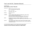
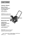
OPERATOR’S
MANUAL
Single Stage
Snowthrower
522E Models
Mfg. No.
1695090
1695091
1695346
7800080
7800083
Description
522E, Snowthrower
522E, Snowthrower (CE)
522E, Snowthrower
SS5220E, Snowthrower
ESS5220E, Snowthrower (CE)
1740187-03
Rev 4/2007
TP 100-4364-03-SW-SN
Table of Contents
CONTENTS:
Regular Maintenance
Lubrication ............................................................16
Troubleshooting & Service
Troubleshooting ....................................................17
Chute Removal and Installation ............................17
Cover Removal and Installation ............................18
Replacing the Drive Belt .......................................19
Servicing the Spark Plug.......................................20
Auger Drive Cable Adjustment..............................21
Appendices
Specifications ........................................................22
Parts & Accessories ..............................................22
Technical Manuals ................................................22
Safety Rules & Information
General............................................................2
Training ............................................................4
Preparation ......................................................4
Operation.........................................................4
Children ...........................................................5
Clearing a Clogged Discharge Chute ..............5
Service, Maintenance and Storage .................5
Emissions ........................................................5
Identification Numbers.....................................6
Decals..............................................................7
Assembling the Snowthrower ............................8
Controls & Operation
Snowthrower Controls...........................................10
Engine & Starting Controls....................................11
General Operation ................................................12
Checks Before Each Start-Up ...............................12
Adding Engine Oil .................................................13
Adding Fuel ...........................................................13
Starting the Engine ...............................................14
Stopping the Engine..............................................14
Operating the Snowthrower ..................................15
Snowthrowing Tips................................................15
After Each Use ......................................................15
Off-Season Storage ..............................................15
Starting After Storage ...........................................15
WARNING
WARNING
You must read, understand and comply with all
safety and operating instructions in this manual
before attempting to set-up and operate your
snowthrower.
Engine exhaust from this product contains
chemicals known, in certain quantities, to cause
cancer, birth defects, or other reproductive harm.
Failure to comply with all safety and operating
instructions can result in loss of machine
control, serious personal injury to you and /or
bystanders, and risk of equipment and property
damage. The triangle in the text signifies
important cautions or warnings which must be
followed.
1
Safety Rules & Information
Operating Safety
Congratulations on purchasing a superior-quality piece of lawn
and garden equipment. Our products are designed and manufactured to meet or exceed all industry standards for safety.
Power equipment is only as safe as the operator. If it is misused, or not properly maintained, it can be dangerous!
Remember, you are responsible for your safety and that of
those around you.
Use common sense, and think through what you are doing. If
you are not sure that the task you are about to perform can be
safely done with the equipment you have chosen, ask a
professional: contact your local authorized dealer.
Read the Manual
The operator’s manual contains important safety information you need
to be aware of BEFORE you operate your unit as well as DURING
operation.
Safe operating techniques, an explanation of the product’s features
and controls, and maintenance information is included to help you
get the most out of your equipment investment.
Be sure to completely read the Safety Rules and Information found on
the following pages. Also completely read the Operation section.
Children
DO NOT ALLOW CHILDREN TO OPERATE THIS UNIT!
This encourages them to come near the unit in the future
while it is running, and they could be seriously hurt.
They may then approach the unit when you are not
expecting it, and you may run over them.
Tragic accidents can occur with children. Do not allow
them anywhere near the area of operation. Children are
often attracted to the unit and snowthrowing activity.
Never assume that children will remain where you last
saw them. If there is a risk that children may enter the
area where you are operating the unit, have another
responsible adult watch them.
TP 600-3606-04-LW-SMA
2
Safety Rules and Information
Moving Parts
This equipment has many moving parts that can injure you or someone else.
However, if you are standing in the operator’s position, and follow all the rules in
this book, the unit is safe to operate.
The auger and impeller have spinning parts that can amputate hands and feet.
Do not allow anyone near the equipment while it is running! DO NOT clear the
discharge chute by hand. If the chute becomes plugged, stop the engine, wait for
all moving parts to stop, and clear the blockage with a clean-out tool or piece of
wood.
To help you, the operator, use this equipment safely, it is equipped with an
operator-present safety system. Do NOT attempt to alter or bypass the system.
See your dealer immediately if the system does not pass all the safety interlock
system tests found in this manual.
Thrown Objects
This unit has a spinning auger and impeller. They
pick up and throw snow and ice. Thrown debris
could seriously injure a bystander. ALWAYS direct
the discharge chute away from bystanders and property that could be damaged by frying debris. Be sure
to clean up the area to be cleared BEFORE you
start.
Do not allow anyone in the area while the unit is running! If someone does enter the area, shut the unit
off immediately until they leave.
Fuel and Maintenance
Gasoline is extremely flammable. Its vapors are also
extremely flammable and can travel to distant ignition
sources. Gasoline must only be used as a fuel, not as a
solvent or cleaner. It should never be stored any place
where its vapors can build up or travel to an ignition source
like a pilot light. Fuel belongs in an approved, plastic,
sealed gas can, or in the snowthrower fuel tank with the
cap securely closed. Spilled fuel needs to be cleaned up
immediately.
Proper maintenance is critical to the safety and performance of your unit. Be sure to perform the maintenance
procedures listed in this manual, especially periodically
testing the safety system.
3
Safety Rules & Information
This machine is capable to amputating hands and feet and throwing objects. Read these safety rules and follow
them closely. Failure to obey these rules could result in loss of control of unit, severe personal injury or death to
you, or bystanders, or damage to property or equipment. The triangle
in text signifies important cautions or
warnings which must be followed.
TRAINING
OPERATION
1. Read, understand, and follow all instructions on the
machine and in the manuals before operating this
unit. Be thoroughly familiar with the controls and the
proper use of the equipment. Know how to stop the
unit and disengage the controls quickly.
2. Never allow children to operate the equipment.
Never allow adults to operate the equipment without
proper instruction.
3. Keep the area of operation clear of all persons, particularly small children and pets.
4. Exercise caution to avoid slipping or falling especially
when operating in reverse.
1. Do not put hands or feet near or under rotating parts.
Keep clear of the discharge opening at all times.
2. Exercise extreme caution when operating on or
crossing gravel drives, walks, or roads. Stay alert for
hidden hazards or traffic.
3. After striking a foreign object, stop the engine (motor),
remove the wire from the spark plug, disconnect the
cord on electric motors, thoroughly inspect the
snowthrower for any damage, and repair the damage
before restarting and operating the snowthrower.
4. If the unit should start to vibrate abnormally, stop the
engine (motor) and check immediately for the cause.
Vibration is generally a warning of trouble.
5. Stop the engine (motor) whenever you leave the
operating position, before unclogging the
collector/impeller housing or discharge guide, and
when making any repairs, adjustments, or inspections.
6. When cleaning, repairing, or inspecting make certain
the collector/impeller and all moving parts have
stopped. Disconnect the spark plug wire and keep
the wire away from the plug to prevent accidental
starting.
7. Do not run the engine indoors except for starting the
engine or for transporting the snowthrower in or out of
the building. Open the outside doors; exhaust fumes
are dangerous.
8. Exercise extreme caution when operating on slopes.
Do not attempt to clear steep slopes.
9. Never operate the snowthrower without proper
guards plates, or other safety protective devices in
place and working.
10. Never direct the discharge toward people or areas
where property damage can occur. Keep children
and others away.
11. Do not overload the machine capacity by attempting
to clear snow at too fast a rate.
12. Never operate the machine at high transport speeds
on slippery surfaces. Look behind and use care
when operating in reverse.
13. Disengage power to the collector/impeller when
snowthrower is transported or not in use.
14. Use only attachments and accessories approved by
the manufacturer of the snowthrower (such as wheel
weights, counterweights, or cabs).
15. Never operate the snowthrower without good visibility
or light. Always be sure of your footing, and keep a
firm hold on the handles. Walk, never run.
16. Never touch a hot engine or muffler.
17. Never operate the snowthrower near glass enclosures, automobiles, window wells, drop-offs, and the
like without proper adjustment of the discharge angle.
18. Never direct discharge at bystanders or allow anyone
in front of the unit.
19. Never leave a running unit unattended. Always disengage the auger and traction controls, stop engine,
and remove keys.
20. Do not operate the unit while under the influence of
alcohol or drugs.
PREPARATION
1. Thoroughly inspect the area where the equipment is
to be used and remove all doormat, sleds, boards,
wires, and other foreign objects.
2. Disengage all clutches and shift into neutral before
starting engine (motor).
3. Do not operate the equipment without wearing adequate winter outer garments. Wear footwear that will
improve footing on slippery surfaces. Avoid loose fitting clothing that can get caught in moving parts.
4. Handle fuel with care; it is highly flammable.
(a) Use an approved fuel container.
(b) Never add fuel to a running engine or hot engine.
(c) Fill fuel tank outdoors with extreme care. Never fill
fuel tank indoors. Replace fuel cap securely and
wipe up spilled fuel.
(d) Never fill containers inside a vehicle or on a truck
or trailer bed with a plastic liner. Always place containers on the ground, away from your vehicle, before
filling.
(e) When practical, remove gas-powered equipment
from the truck or trailer and refuel it on the ground. If
this is not possible, then refuel such on a trailer with a
portable container, rather than from a gasoline dispenser nozzle.
(f) Keep nozzle in contact with the rim of the fuel tank
or container opening at all times, until refueling is
complete. Do not use a nozzle lock-open device.
(g) Replace gasoline cap securely and wipe up spilled
fuel.
(h) If fuel is spilled on clothing, change clothing immediately.
5. Use extension cords and receptacles as specified by
the manufacturer for all units with electric drive
motors or electric starting motors.
6. Adjust the collector housing height to clear gravel or
crushed rock surfaces.
7. Never attempt to make any adjustments while the
engine (motor) is running (except when specifically
recommended by the manufacturer).
8. Let engine (motor) and machine adjust to outdoor
temperatures before starting to clear snow.
9. Always wear safety glasses or eye shields during
operation or while performing an adjustment or repair
to protect eye from foreign objects that may be
thrown from the machine.
4
Safety Rules
8. Always follow the engine manual instructions for storage preparations before storing the unit for both short
and long term periods.
9. Always follow the engine manual instructions for
proper start-up procedures when returning the unit to
service.
10. Maintain or replace safety and instruction labels as
necessary.
11. Keep nuts and bolts tight and keep equipment in
good condition.
12. Never tamper with safety devices. Check their proper
operation regularly and make necessary repairs if
they are not functioning properly.
13. Components are subject to wear, damage, and deterioration. Frequently check components and replace
with manufacturer’s recommended parts, when necessary.
14. Check control operation frequently. Adjust and service as required.
15. Use only factory authorized replacement parts when
making repairs.
16. Always comply with factory specifications on all settings and adjustments.
17. Only authorized service locations should be utilized
for major service and repair requirements.
18. Never attempt to make major repairs on this unit
unless you have been properly trained. Improper service procedures can result in hazardous operation,
equipment damage and voiding of manufacturer’s
warranty.
19. Check shear bolts and other bolts at frequent intervals for proper tightness to be sure the equipment is
in safe working condition.
21. Keep in mind the operator is responsible for accidents occurring to other people or property.
22. Data indicates that operators, age 60 years and
above, are involved in a large percentage of power
equipment-related injuries. These operators should
evaluate their ability to operate the unit safely enough
to protect themselves and others from injury.
23. DO NOT wear long scarves or loose clothing that
could become entangled in moving parts.
24. Snow can hide obstacles. Make sure to remove all
obstacles from the area to be cleared.
CHILDREN
Tragic accidents can occur if the operator is not alert to the
presence of children. Children are often attracted to the
unit and the operating activity. Never assume that children
will remain where you last saw them.
1. Keep children out of the area and under the watchful
care of another responsible adult.
2. Be alert and turn unit off if children enter the area.
3. Never allow children to operate the unit.
4. Use extra care when approaching blind corners,
shrubs, trees, or other objects that may obscure
vision.
CLEARING A CLOGGED DISCHARGE
CHUTE
Hand contact with the rotating impeller inside the discharge chute is the most common cause of injury associated with snowthrowers. Never use your hand to clean
out the discharge chute.
To clear the chute:
1. SHUT OFF THE ENGINE.
2. Wait 10 seconds to be sure the impeller blades have
stopped rotating.
3. Always use a clean out tool, not your hands.
EMISSIONS
1. Engine exhaust from this product contains chemicals
known, in certain quantities, to cause cancer, birth
defects, or other reproductive harm.
2. If available, look for the relevant Emissions Durability
Period and Air Index information on the engine emissions label.
SERVICE, MAINTENANCE, AND STORAGE
1. Check shear bolts and other bolts at frequent intervals for proper tightness to be sure the equipment is
in safe working condition.
2. Never store the machine with fuel in the fuel tank
inside a building where ignition sources are present
such as hot water and spacer heaters, or clothes dryers. Allow the engine to cool before storing in any
enclosure.
3. Always refer to the operator’s manual for important
details if the snowthrower is to be stored for an
extended period.
4. Maintain or replace safety and instruction labels as
necessary.
5. Run the machine a few minutes after throwing snow
to prevent freeze-up of the collector/impeller.
6. If fuel is spilled, do not attempt to start the engine but
move the machine away from the area of spillage and
avoid creating any source of ignition until fuel vapors
have dissipated.
7. Always observe safe refueling and fuel handling practices when refueling the unit after transportation or
storage.
IGNITION SYSTEM
1. This spark ignition system complies with Canadian
ICES-002.
5
Product Identification
Identification Numbers
SA
M
North American
Models
PL
E
ID Tag
Part No. xxxxxxx
SA
M
xxxxxxxxxxxxxxx
Serial No. xxxxxxxxxx
CE Models
xxx
PL
20xx
E
xxxxxxxxxxxxxxxxxxxxxxx
xxxxxxxxxxxxxxxxxxxxxxx
xxxxxxxxxxxxxxxxxxxxxxx
xxxxxxxxxxxxxxxxxxxxxxx
PRODUCT
dB
kg: xxx
kW: x.xx
xxxx max
When contacting your authorized dealer for replacement parts, service, or information you MUST have
these numbers.
Record your model name/number, manufacturer’s identification numbers, and engine serial numbers in the
space provided for easy access. These numbers can be
found in the locations shown.
DATA
Unit MFG Number
Unit SERIAL Number
Mower Deck MFG Number
Mower Deck SERIAL Number
Dealer Name
Date Purchased
ENGINE REFERENCE DATA
NOTE: For location of engine identification numbers,
refer to the engine owner’s manual.
Engine Make
Engine Model
Engine Type/Spec
Engine Code/Serial Number
CE IDENTIFICATION TAG MARKINGS
A.
B.
C.
D.
E.
F.
G.
H.
I.
REFERENCE
Model Description Name/Number
A
Part Number
Manufacturer’s Serial Number
Power Rating in Kilowatts
Maximum Engine Speed in Rotations per Minute
Manufacturer’s Address
Year of Manufacture
CE Compliance Logo
Mass of Unit in Kilograms
Sound Power in Decibels
Part No. xxxxxxx
B
E
I
xxxxxxxxxxxxxxx
Serial No. xxxxxxxxxx
xxx
xxxxxxxxxxxxxxxxxxxxxxx
xxxxxxxxxxxxxxxxxxxxxxx
xxxxxxxxxxxxxxxxxxxxxxx
xxxxxxxxxxxxxxxxxxxxxxx
20xx
F
6
dB
kg: xxx
kW: x.xx
xxxx max
G
H
C
D
Product Identification
SAFETY DECALS
Safety warning decals are placed at strategic locations on the snowthrower as a constant reminder to the operator of the most important safety precautions. All warning, caution and instructional messages on your snowthrower should be carefully read and obeyed. If any of these decals are lost or damaged, replace them at once. They
can be purchased from your local dealer.
Part No. 69880MA
North American Hot Surface Decal
Part No. 1740428MA
North American - Danger / Warning
Main Dash Decal
Part No. 48x5638MA
North American Electric Start Decal
Part No. 1740422MA
All - Choke Decal
Part No. 70141MA
North American Auger Danger Decal
Part No. 1740400MA
CE - Danger / Warning
Main Dash Decal
Part No. 48x6000MA
CE - Electric Start
Decal
Part No. 48x5998MA
CE - Auger Control Decal
Part No. 761150MA
North American - Auger Decal
Part No. 48x5642
North American Unclogging Chute
Danger Decal
Part No. 48x5999MA
CE - Hot Surface
Danger Decal
Part No. 48x5995MA
CE - Auger Danger
Decal
Part No. 48x5994MA
CE - Chute Danger
Decal
International Symbols
FAST
SLOW
CHOKE
STOP
PRIMER
ELECTRIC
START
7
RUN
IGNITION
KEY
Assembling
the Snowthrower
TOOLS REQUIRED
A
• Knife
E
F
REMOVAL FROM CARTON
B
C
1. Locate and remove container of oil.
D
2. Locate all parts packed separately and remove from
carton.
C
Note: Set the fuel stabilizer aside until adding gasoline to
the fuel tank. We recommend that fuel stabilizer be
added to the fuel each time that gasoline is added to the
fuel tank.
3. Remove and discard the packing material from
around the snow thrower.
4. Cut down all four corners of the carton and lay the
panels flat.
5. Hold onto the lower handle and pull the snow thrower
off the carton.
Figure 1. Snowthrower (Shown Assembled)
A. Auger Drive Lever
B. Auger Drive Cable
C. T-Knobs
D. Chute Deflector
E. Crank Assembly
F. Recoil Starter
CAUTION: DO NOT back over cables.
6. Remove the packing material from the handle assembly.
ASSEMBLY PROCEDURE
Snowthrower
If your unit was not previously assembled, see Figure 1
and follow the steps below to assemble the unit:
1. Lift up folding handle to align it with lower handle and
tighten the t-knobs securely as shown in Figure 2.
Figure 2. Lift Handles and T-Knobs
8
Assembling the Snowthrower
A
A
C
B
B
C
Figure 3. Z-Hook Installation
A. Auger Drive Lever
B. Z-Hook
C. Auger Drive Cable
Figure 4. Upper Chute Installation
A. Upper Chute
B. T-Knob
C. Lower Chute
2. Attach the auger drive cable (C, Figure 3) to the
auger drive lever (A) using the Z-hook (B).
3. Remove the t-knob (B, Figure 4) and bolt on the
upper chute.
4. Rotate the upper chute (A) to the operating position
(past the lower chute stop)
5. Install the bolt and tighten the t-knob (B).
A
Engine
C
1. The snow thrower was shipped with a container of
5W30engine oil. Before operating, add this oil to the
engine.
2. Remove the oil fill cap/dipstick access panel (A,
Figure 5).
3. Remove the oil fill cap/dipstick (B). Fill to the FULL
mark on the oil fill cap/dipstick. Periodically check the
oil level. DO NOT OVER FILL.
B
4. If not installed, install the fuel cap (C) onto the fuel
tank.
Figure 5. Add Engine Oil
A. Access Panel
B. Oil Fill Cap/Dipstick
C. Fuel Cap
9
Controls
& Operation
SNOWTHROWER CONTROLS
A
Auger Control
B
A. Auger Control - This control engages and disengages the auger. Pull the control back against handle
to engage the auger, (this will pull snowthrower forward if auger is in contact with the ground). Release
the Auger Control to stop rotation of auger.
C
Deflector Controls
B. Chute Direction Control - The Chute Direction
Control (B, Figures 6 & 7) allows the discharge chute
to be rotated to throw snow in the desired direction.
Snow may be thrown at any angle from straight left to
straight forward, to straight right.
The length of the chute direction control can be
adjusted. Remove the cotter pin (A, Figure 6) to
extend or shorten the rod to desired length, then reinstall the pin.
C. Chute Deflector - Controls the distance snow is
thrown. Tilting the Chute Deflector (C, Figure 7) UP
provides a higher stream and greater distance, while
tilting the deflector DOWN provides a lower stream
and less distance.
Figure 7. Snowthrower Controls
A
B
Figure 6. Discharge Chute Control Adjustment
A. Cotter Pin
B. Chute Direction Control
10
A Auger
Control
Engages auger when pulled
back, and disengages auger
when released.
B Chute
Direction
Control
Rotates discharge chute to
desired direction
C Chute
Deflector
Controls vertical angle snow is
thrown.
Controls & Operation
ENGINE & STARTING CONTROLS
NOTE: Throttle - This snow thrower does NOT have a
throttle for controlling operating speed of engine. The
engine governor maintains operating speed for varying snow removal conditions.
B
A. Electric Start Button - The Electric Start Button (A,
Figure 8) activates an electric starter mounted to the
engine, eliminating the need to pull the starter handle. The Electric Start Button operates on 120 Volts
AC, which is provided by connection to the extension
cord provided with units equipped with this feature.
Connect this extension cord ONLY to a properly
grounded 3 prong electrical outlet.
C
E
B. Fuel Tank Cap - Cover fuel tank & provides venting
ability to prevent vapor lock.
A
F
C. Starter Handle - The starter handle (C) connects to a
starter cord to manually start the engine. Pulling
starter handle rapidly spins the engine crankshaft,
cycles the engine, and generates the spark necessary for starting the engine.
D
D. Primer Button - When pressed, the Primer Button
(D) provides initial fuel to help start a cold engine.
Normally, pressing the primer button twice will provide enough fuel to start a cold engine.
Figure 8. Engine Controls
A
E. Engine Key - Insert key in switch and turn key to ON
position when starting engine. To stop engine, turn
key to OFF position.
F. Choke Control - The is control (F) adjusts the fuel/air
mixture, and is used to help start a cold engine by
providing a richer mixture.Once the engine is warm
and running smoothly, the Choke Control should be
set to the off position to provide a normal air/fuel mix.
11
Electric Start
Button
(Optional)
Activates electric starter
B Fuel Tank
Cap
Covers fuels tank and provides
venting to prevent vapor lock
C Starter Handle
Used to start engine
D Primer Button
Primes carburetor for faster cold
starting.
E
Engine Key
Prevents starting of engine without key. Stops engine when
removed.
F
Choke Control
Adjusts air/fuel mixture
Controls & Operation
GENERAL OPERATION
WARNING
CHECKS BEFORE EACH START-UP
OPERATIONAL WARNINGS
1. Make sure all safety guards are in place and all nuts,
bolts and clips are secure.
Clearing The Discharge Chute
To avoid serious injury, do not put your hands
into the auger housing or discharge chute. If the
auger stalls or chute becomes plugged, use the
following procedure to remove objects or clear
the chute:
1. Release the auger control.
2. Shut off the engine.
3. Remove the key.
4. Wait for all moving parts to stop.
5. Use the clean-out tool to remove foreign
objects and clear the chute or auger. Never
put your hands into the auger or discharge
chute.
6. If servicing is needed, remove cover and
disconnect spark plug wire.
2. Check the fuel supply. Fill the tank no closer than 1/4
to 1/2 inch of top of tank to provide space for expansion. See your engine Owner’s Manual for fuel recommendations.
3. Check the Auger Control (A, Figure 7) for proper
operation. If adjustment is required, see the Service
Section for procedures.
4. Check the Chute Direction Control (B, Figure 7) for
proper operation. The discharge chute should rotate
freely in both directions. See the Service section for
adjustment procedures and troubleshooting.
5. Check the Chute Deflector (C, Figure 7) for proper
operation. The deflector should pivot freely up and
down. See the Service Section for procedures.
6. Position the chute at the desired starting direction
and set the deflector at the desired angle.
Discharge Chute Adjustment
Release the auger control and make sure the
auger has STOPPED before rotating the
discharge chute or adjusting the deflector. DO
NOT place hands near the auger while the engine
is running.
DANGER
Thrown Objects
Never run engine indoors or in enclosed, poorly
ventilated areas. Engine exhaust contains
CARBON MONOXIDE, an ODORLESS and
DEADLY GAS.
Objects can be thrown by the snowthrower while
it is in operation. Thrown objects could cause
serious injury to the operator or bystanders.
Always wear safety goggles or other suitable eye
protection. Keep people and pets away from the
area.
Slope Operation
DANGER
For your safety, operation on slopes should be in
an up and down direction only. If it becomes
necessary to move across the face of a slope,
use caution and do not activate the auger. Be
very careful when changing direction on a slope.
DO NOT clean out discharge chute with hands.
Contact with moving parts in the chute will cause
serious injury. Use clean-out tool provided with
machine.
Proper winter footwear is recommended for the
operator to help prevent slipping. Never attempt
to clean snow from slopes. The maximum slope
for any operation is 17.7% (10º).
Do not use the snowthrower on surfaces above
ground level such as the roof of a building.
12
Controls & Operation
ADDING ENGINE OIL
1. Make sure the unit is level. Use a high quality detergent oil classified “For Service SG, SH, SJ, SL, or
higher”.
A
2. Remove the oil fill cap/dipstick access panel (A,
Figure 9).
C
2. Remove the oil fill cap/dipstick (B) and wipe with a
clean cloth.
3. Insert the oil fill cap/dipstick (B) and turn clockwise to
tighten.
4. Remove the oil fill cap/dipstick (B) and check the oil.
NOTE: Do not check the level of the oil while the engine
is running.
B
5. If necessary, add oil until the oil reaches the FULL
mark on the oil fill/cap dipstick (see Figure 9). Do not
add too much oil.
6. Tighten the fill cap/dipstick securely each time you
check the oil level.
Figure 9. Add / Check Engine Oil and Gasoline
A. Access Panel
B. Oil Fill Cap/Dipstick
C. Fuel Cap
NOTE: For extreme cold operating conditions of 0°F(-18°
C) and below, use a synthetic 5W30 motor oil for easier
starting.
NOTE: S.A.E. 5W30 motor oil may be used to make
starting easier in areas where the temperature is 20° F
(-7° C) to 0F (-18° C). Synthetic 5W30 is acceptable for
all temperatures. DO NOT mix oil with gasoline.
We recommend that fuel stabilizer be added to the
fuel each time that gasoline is added to the fuel tank.
Refer to your engine manual for further specific fuel
recommendations.
NOTE: SEE CHART FOR OIL RECOMMENDATION
3. Install and hand tighten the fuel cap.
Use oil classified API Service Class SF,
SG, SH, SJ or better with SAE Viscosity:
NOTE: Winter grade gasoline has higher volatility to
improve starting. Be certain container is clean and
free from rust or other foreign particles. Never use
gasoline that may be stale from long periods of storage in the container.
5W-30 Conventional
CAUTION: DO NOT use gasoline containing any amount
of alcohol as it can cause serious damage to the engine
or significantly reduce the performance
5W-30 Synthetic
˚F
-20
0
20
32
40
˚C
-30
-18
-7
0
4
WARNING
Gasoline is highly flammable and must be
handled with care. Never fill the tank when the
engine is still hot from recent operation. Do not
allow open flame, smoking or matches in the
area. Avoid over-filling and wipe up any spills.
ADDING FUEL
To add fuel:
1. Remove the fuel cap (C, Figure 9).
2. Fill the tank. Do not overfill. Leave room in the tank
for fuel expansion. Fill the fuel tank with fresh, clean,
unleaded regular, un-leaded premium, or reformulated automotive gasoline with a minimum of 85 octane
along with a fuel stabilizer (follow instructions on fuel
stabilizer package). DO NOT use leaded gasoline.
Do not use gasoline containing METHANOL,
gasohol containing more than
10% ETHANOL, gasoline additives, or white
gas because engine/fuel system damage
could result.
13
Controls & Operation
STARTING THE ENGINE
7. Disconnect power cord from household receptacle
and then from starter switch on snowthrower. Store
cord in a dry, convenient place.
NOTE: The snowthrower engine is designed to operate
at cold temperatures. Avoid operating the snowthrower if
air temperature is 40° F or warmer since engine may
vapor lock and stop running after a short time. Engine
will be difficult to start in warm weather.
8. To stop engine, turn engine key to the OFF position.
Manual (Recoil) Starting Steps
1. Insert engine key in switch and turn key to the ON
position.
WARNING
2. If engine is cold, move choke control lever to the ON
position. (Do not choke a warm engine).
Electric start precautions:
3. Push the primer button two times if engine is cold.
(Do not prime a warm engine.)
• Use only with a grounded, polarized 120V AC
outlet. Do not modify the plug to fit into any
other type of outlet.
4. Grasp starter rope handle and slowly pull out rope
until resistance is felt. Allow rope to rewind slowly,
then pull rope out rapidly to start engine. Let rope
return slowly to starter.
• Use only the power cord supplied with the unit.
DO NOT use a damaged cord.
• Be sure there is no moisture present on the
cord ends or receptacles when connecting to
an outlet or to the unit.
NOTE: If engine does not start after three pulls,
push primer bulb once and again pull starter
rope.
5. After engine starts and gradually warms up, move
choke lever to the OFF position. Be prepared to
move choke lever to the ON position if engine falters
during warm up.
Electric Starting Steps
Note: The electric starter is designed to operate on 120V
AC household current, using power cord supplied with
electric start snowthrower. When using power cord,
match wide blade of plug to wide slot of receptacle.
6. Allow engine to warm up before beginning
snowthrower operations. The engine will operate at
full throttle when thoroughly warmed up.
1. Insert engine key in switch and turn key to the ON
position.
7. To stop engine, turn engine key to the OFF position.
2. If engine is cold, move choke control lever to the ON
position. (Do not choke a warm engine).
DANGER
Never run engine indoors or in enclosed, poorly
ventilated areas. Engine exhaust contains
CARBON MONOXIDE, an ODORLESS and
DEADLY GAS.
3. Push the primer button two times if engine is cold.
(Do not prime a warm engine.)
4. Plug power cord for starter into receptacle on starter
switch, then plug other end into a 120Volt AC household receptacle. DO NOT use an extension cord with
the electric start power cord supplied.
STOPPING THE ENGINE
5. Push starter button to crank engine. DO NOT crank
engine for more than a total of 15 seconds without
allowing electric starter to cool for 10 minutes before
additional cranking is attempted. Electric starter can
be severely damaged if recommended starter operating limitations are not observed.
1. Release the auger control.
2. Turn engine key to the OFF position.
3. Remove the key from the switch if you are leaving the
operating position or will be making adjustments or
repairs. (NOTE: Allow the unit to cool before storing
or making any adjustments or repairs.)
NOTE: Do not push primer button while engine is
being cranked.
If you will be storing the unit for the season, see the
STORAGE section for instructions on properly preparing
the unit for long-term storage.
6. Release starter button when engine starts and gradually move choke lever to the OFF position.
NOTE: Always disconnect power cord from
household receptacle first, then unplug from
starter switch.
14
Controls & Operation
OPERATING THE SNOWTHROWER
Always be alert to hidden hazards that might be struck
by the auger. Should a foreign object be struck by the
auger, immediately stop the engine and inspect machine
for any damage. Repair damage before continuing operation.
Before operating snowthrower, review the Checks Before
Each Use under General Operation on page 12 of this
manual.
1. Rotate the discharge chute to the desired direction.
AFTER EACH USE
2. Pull the Auger Control back against the handle to
engage the auger.
Allow snow thrower to run a few minutes after clearing
snow to reduce the likelihood of parts freezing while
machine is not is use.
NOTE: The snowthrower will be pulled forward by the
auger when the auger contacts the ground or with the
snow to be thrown.
If you will be storing the unit for the season, see the
STORAGE section for instructions on properly preparing
the unit for long-term storage.
3. Begin snow removal by clearing a path down the center of walk or driveway, then gradually widen path,
throwing snow off to both sides.
OFF-SEASON STORAGE
Before you store your snowthrower for the off-season,
read the Service, Maintenance and Storage instructions
in the Safety Rules section and take the following precautions:
4. Release the auger control to stop both the auger and
the forward motion of the snowthrower.
DANGER
NOTE: Gasoline, if permitted to stand unused for extended periods (30 days or longer), may develop gummy
deposits which can adversely affect the engine carburetor and cause engine malfunction. To avoid this condition, add Dealer Line Gasoline Stabilizer to the fuel tank,
or drain all fuel from the system before placing unit in
storage.
Do not clean out discharge chute with hands.
Contact with moving parts inside chute will
cause serious injury. Use clean out tool
provided with machine. Use the following
procedure to remove objects or clear the chute:
1. Stop the engine. Remove the key
2. Wait 10 seconds to be sure the auger/impeller
blades have stopped rotating.
3. Always use the clean-out tool. DO NOT use your
hands.
NOTE: Refer to the engine manufacture's owner’s manual for engine storage information.
1. Drain fuel from the fuel tank and let the engine run
until all fuel is consumed and the engine stops. Allow
the unit to cool.
2. Disconnect the spark plug wire and secure away from
the spark plug.
SNOWTHROWING TIPS
Discharge chute plugging may occur as the result of
snow build up inside the chute. DO NOT use your hands
to clear the blockage, only use the clean-out tool. DO
NOT place your hands near the auger or discharge chute
any time the engine is running. Turn the engine OFF, be
sure all moving parts have stopped, and clear the blockage using the clean-out tool, or put the unit indoors and
allow the blockage to melt.
3. Tape all openings to prevent spraying water into the
exhaust or air intakes.
4. Tilt the snowthrower up on its wheels and thoroughly
clean the underside.
5. Lubricate all exposed metal with a light coating of oil.
DO NOT place any type of lubrication on the drive
belt or pulleys.
Varying snow conditions will affect performance of
snowthrower. The snowthrower should be allowed to
move into the snow at it's own pace.
6. Store the unit in a shelter or other dry area protected
from the weather.
Wet, heavy snow — When clearing wet, heavy snow,
the forward movement of the snowthrower may have to
be slowed by pushing down on handle while allowing
engine to operate at full throttle.
STARTING AFTER STORAGE
1. Remove the spark plug and wipe dry. Then reinstall
plug.
2. Fill fuel tank with fresh gasoline (unless a fuel stabilizer was used).
3. Check to be sure engine fins are clean and air flow is
unobstructed.
4. Start the engine outdoors. Allow the engine to warn
up before blowing snow.
Do not operate on gravel or crushed rock surfaces.
Avoid picking up this type of material with auger since
damage to unit could result and particles can be discharged with considerable force that could cause serious
injury.
5. Check the operation of all the controls.
15
Regular
Maintenance
WARNING
Before beginning any repair stop the engine,
remove the key, disconnect the spark plug wire,
and wait for all moving parts to stop.
LUBRICATION
Note: The drive pulley end of auger shaft is supported by
a sealed ball bearing and requires no lubrication. The
ball bearing on other end of auger shaft is also sealed,
and will not require lubrication.
Lightly Oil
• A few drops of oil should be placed on wheel
hubs occasionally to keep wheels turning
freely.
Figure 10. Lubrication points
• Apply oil to pivot points of auger control periodically, wiping off any excess oil.
• A couple of drops of light machine oil applied to
upper end of auger control cable will assure free
movement of cable through outside casing. Wipe off
any excess oil.
• Remove belt cover and lightly apply oil to the pivot
point for idler pulley arm. BE CAREFUL NOT TO
GET OIL ON BELT OR PULLEYS.
Lubricate
Flange
Grease
Figure 11. Grease the Discharge Chute Ring
• At the beginning of each snow throwing season, remove discharge chute and generously
lubricate steel flange at back of rotating ring
with light grease. Rotate ring with crank to distribute grease.
16
Troubleshooting
& Service
TROUBLESHOOTING
Problem
Possible Cause
Remedy
Engine fails to start
1. Key is OFF
2. Failure to prime cold engine
3. Out of fuel
4. Choke OFF - cold engine
5. Engine flooded
6. Spark Plug not sparking
1. Turn Key to the ON position
2. Press primer button twice and restart.
3. Fill fuel tank
4. Turn Choke to ON.
5. Turn Choke to OFF; try starting
6. Check Gap. Gap plug, clean electrode,
or replace as necessary
7. Drain tank (Dispose of fuel at an authorized
waste facility). Fill with fresh fuel mixture.
7. Water in fuel, or old fuel
Engine starts hard or runs poorly
1. Fuel mixture too rich
2. Spark plug faulty, fouled,
or gapped incorrectly
3. Water in fuel, or old fuel
1. Move choke to OFF position
2. Clean and gap, or replace
3. Drain tank (Dispose of fuel at an authorized
waste facility). Fill with fresh fuel mixture.
4. Clean vent hole or replace cap
4. Gas cap vent hole plugged
Unit does not throw snow
1. Loose or broken drive belt
2. Incorrect control cable
adjustment
3. Discharge chute clogged,
foreign object lodged in auger
4. Broken control cable
1. Adjust or replace belt
2. Adjust Auger Control cable
3. Stop engine, remove key and
clean out discharge chute
4. Replace cable
Auger does not stop turning
when control is released
1. Incorrect control cable
adjustment
1. Adjust Auger Control cable
Excessive vibration
1. Loose parts or damaged
auger
1. STOP engine and REMOVE the key,
tighten all hardware. If vibration
continues, see your dealer.
Note: For repairs beyond the minor adjustments listed above, please contact your local dealer.
CHUTE REMOVAL AND
INSTALLATION
A
1. Remove the fasteners (B, Figure 12) that secure the
chute (A) to the top cover.
2. Remove the chute (A).
B
B
3. Installation is reverse of removal.
B
B
Figure 12. Chute Removal and Installation
A. Chute
B. Fastners
17
Troubleshooting & Service
COVER REMOVAL AND
INSTALLATION
REMOVE THE BELT COVER
1. Remove the screws (B, Figure 13) and nuts that hold
the belt cover (E) to the auger housing.
To access the drive system or the engine, the covers
must be removed as follows:
REMOVE THE TOP COVER
2. If the top cover (D) has not been removed, then
remove the screws (C) that attach the belt cover to
the top cover.
1. Remove the discharge chute. See “How To Remove
The Chute”.
3. Remove screw (C) that holds the belt cover (E) to the
top cover (D).
2. Remove the fuel cap.
4. To remove, hold the bottom portion of the belt cover
(E) and pull down and out.
3. Remove the screws (A, Figure 13) and nuts from the
front of the top cover (D).
5. Installation of belt cover (E) is reverse of removal.
4. Remove the screws (B) and nuts from the left and
right side of the top cover (D).
5. Remove the eight screws (C) on the left and right
side of the top cover (D).
6. Remove the five screws (C) from the back portion of
the control panel.
7. Carefully pull the rear of the top cover up and over
the gas tank.
8. Installation of top cover (D) is reverse of removal.
C
C
A
C
B
A
Figure 13. Top Cover
and Belt Cover
A. Screw, 1/4-20 x 5/8
B. Screw, #10-24 x 1/2
C. Screw, 1/4-14 x 3/4
D. Top Cover
E. Belt Cover
C
D
C
B
E
B
B
18
C
REPLACE DRIVE BELT
The drive belt is of special construction and must be
replaced with original factory replacement belt available
from your nearest dealer.
A
F
1. Remove the belt cover. See “How To Remove The
Belt Cover”.
B
E
2. Remove the drive belt (E, Figure 14) from the idler
pulley (G).
3. Move the belt guide (B) away from the drive belt (E).
C
4. To reduce pressure on the drive belt (E), move the
idler pulley (G) away from the belt. Remove the drive
belt (E) from between the brake pad (F) and the
brake roller (D).
D
5. Remove the old drive belt (E).
6. To install the new drive belt (E) , reverse the above
steps.
Figure 14. Drive Belt Installation
A. Engine Pulley
B. Belt Guide
C. Brake Roller
D. Drive Belt
E. Brake Pad
F. Idler Pulley
7. Make sure the drive belt (E) is seated properly on the
pulleys.
8. Set the belt guide to 3/32” clearance as shown in
Figure 15.
NOTE: When the auger control lever is engaged,the belt
guide must be 3/32” (23.mm) from the drive belt.
9. Install belt cover. See “How To Remove The Belt
Cover
A
3/32 “ (2.3mm)
Figure 15. Belt Guide
19
Troubleshooting & Service
SERVICING THE SPARK PLUG
1. Remove engine key from switch.
2. Remove the oil access cover.
3. Disconnect the wire from the spark plug.
4. Inspect the spark plug and clean. If necessary,
replace it with a new spark plug as recommended in
the engine owners manual.
5. Adjust the gap on the spark plug to .030 inches (.762
mm) using a gauge.
Spark Plug
Wire
6. Reinstall the plug and tighten firmly, torque to 18-23
ft.lbs.
7. Reconnect spark plug wire.
Figure 16. Servicing Spark Plug
8. Reinstall engine cover.
20
Troubleshooting & Service
AUGER DRIVE CABLE ADJUSTMENT
The auger drive cable is adjusted at the factory and no
adjustment should be necessary. If the cable becomes
stretched or is sagging, adjustment will be necessary.
A
Whenever the belt is adjusted or replaced, the cable will
need to be adjusted.
B
1. Remove the z-hook (C, Figure 18) from the auger
drive lever (A).
C
2. Slide the cable boot, (A, Figure 1) if equipped, up the
auger control cable (B) until the cable boot does not
cover any portion of the cable adjustment bracket
(D).
Figure 17. Z-Hook Installation
A. Auger Drive Lever
B. Z-Hook
C. Auger Drive Cable
3. Pull the auger control cable (B) through the eyehole
in the cable adjustment bracket (D) as shown by the
arrow in Figure 18. This will create enough slack to
allow the “Z” hook to be easily removed.
4. Install the “Z” hook (C) into the next available adjustment hole in the cable adjustment bracket (D). This
is the adjustment hole located one notch down from
where the“Z” hook (C) was previously attached.
5. Pull the auger control cable (B) back through the eyehole of the cable adjustment bracket (D) until all the
slack is taken out of the auger control cable (B).
A
6. Slide the cable boot (A) back down over the cable
adjustment bracket(D).
B
B
7. Install the “Z” hook (B, Figure 18) to the auger drive
lever (A).
C
D
C
Figure 18. Traction Drive Cable Adjustment
A. Cable Boot
B. Auger Control Cable
C. “Z” Hook
D. Cable Adjustment Bracket
21
Specifications
NOTE: Specifications are correct at time of printing and are subject to change without notice.
* The gross power rating for individual gas engine models is labeled in accordance with SAE (Society of Automotive
Engineers) code J1940 (Small Engine Power & Torque Rating Procedure), and rating performance has been
obtained and corrected in accordance with SAE J1995 (Revision 2002-05). Torque values are derived at 3060 RPM;
horsepower values are derived at 3600 RPM. Actual gross engine power will be lower and is affected by, among
other things, ambient operating conditions and engine-to-engine variability. Given both the wide array of products on
which engines are placed and the variety of environmental issues applicable to operating the equipment, the gas
engine will not develop the rated gross power when used in a given piece of power equipment (actual "on-site" or net
power). This difference is due to a variety of factors including, but not limited to, accessories (air cleaner, exhaust,
charging, cooling, carburetor, fuel pump, etc.), application limitations, ambient operating conditions (temperature,
humidity, altitude), and engine-to-engine variability. Due to manufacturing and capacity limitations, Briggs & Stratton
may substitute an engine of higher rated power for this Series engine.
ENGINE:
CHASSIS:
5.25 Series Briggs & Stratton
Spout Rotation
Auger Diameter
Tire Size
Make
Domestic
Model / Type
CE
Model / Type
Briggs & Stratton
Gross Torque*
5.25 ft. lbs. @ 3060 rpm
Displacement
9.02 Cu. in (148 cc)
190 Degrees
9” (22.9 cm)
7” x 1.5” (17.8 cm x 3.8 cm)
DIMENSIONS:
09A413 / 0202E1
Effective Clearing
Width
Length
Height
Weight
09A413 / 0203E1
22” (51 cm)
42” (107 cm)
42” (107 cm)
75 lbs (34 kg)
Parts & Accessories
For applicable manuals currently available for your
model, contact our Customer Publications Department at
262-284-8519. Have the information listed in the box
below available when phoning in your request.
Technical manuals can be downloaded from:
REPLACEMENT PARTS
Replacement parts are available from your authorized
dealer. Always use genuine Simplicity/Snapper Service
Parts.
www.simplicitymfg.com
MAINTENANCE ITEMS
www.snapper.com
Many convenient and helpful service and maintenance
items are available from you authorized dealer. Some of
these items include:
Engine Oil
Touch-Up Paint
Grease Gun Kit
8 oz. Grease Tube
Model:
Tire Sealant
Degrimer/Degreaser
Gas Stabilizer
Mfg. No.:
Your Name:
TECHNICAL MANUALS
Address:
Additional copies of this manual are available, as well as
fully illustrated parts lists. These manuals show all of the
product’s components in exploded views (3D illustrations
which show the relationship of parts and how they go
together) as well as part numbers and quantities used.
Important assembly notes and torque values are also
included.
City, State, Zip:
Visa/Mastercard No.:
Card Expiration Date:
22
MANUFACTURING, INC.
500 N Spring Street / PO Box 997
Port Washington, WI 53074-0997
www.SimplicityMfg.com
PRODUCTS
535 Macon Street
McDonough, GA 30253
www.Snapper.com
© Copyright 2007, BRIGGS & STRATTON.
All Rights Reserved. Printed in USA.