1
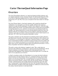
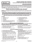
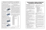
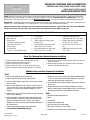
EDELBROCK PERFORMER SERIES CARBURETORS
CATALOG #1403 #1404, #1405, #1406, #1407, #1409,
#1410, #1411, #1412 & #1413
PostScript Picture
(Edelbrock B/W Logo.eps)
INSTALLATION INSTRUCTIONS
PLEASE study these instructions and the "Important Information Regarding Edelbrock Performer Series Carburetors" completely and thoroughly
before installing your new carburetor. If you have any questions or problems, contact our Technical Hotline at: 1-800-416-8628, 7 am - 5 pm
Monday-Friday, Pacific Standard Time or e-mail us at [email protected]. Please fill out and return the EPS carburetor Warranty Card.
DESCRIPTION: The Edelbrock Performer Series carburetor has been calibrated, factory flow-tested, and preset. Please read all instructions prior to
installation. For "Theory of Operation" and "Tuning Procedures", see the accompanying carburetor Owner's Manual.
Edelbrock Performer Series carburetors are not for computer-controlled applications. That includes some 1981 & later GM vehicles
with Q-Jet carburetor and some 1981 & later Ford vehicles with automatic overdrive (AOD) transmissions.
INSTALLATION KIT CONTENTS
11111111-
Installation instruction sheet
Owner’s Manual
Warranty card
Carburetor accessories brochure
Square-bore base gasket
Air horn gasket
Air cleaner stud
Vacuum “T” (except #1409 &1410)
12111-
1/4" pipe plug
Vacuum caps
Throttle cable ball end stud (except
#1409 & 1410)
Red choke positive wire (1403, 1406,
1409, 1410, 1411 & 1413 only)
Black choke ground wire (1403, 1406,
1409, 1410, 1411 & 1413 only)
4111-
Carburetor studs/nuts/washers
(1406,1409,1410,1411 & 1413 only)
#8018 Transmission kick-down stud
for 1406, 1411 & 1413 only
Vacuum hose (1406, 1411 & 1413
only)
#8009 Throttle cable stud for 1406,
1411 & 1413
Check The Following Items Before Carburetor Installation
❑
❑
❑
❑
❑
Replace fuel filter. Dirt found in carburetor voids warranty.
Check and replace the air filter if necessary.
Check PCV valve and replace if clogged.
Check all hoses for leaks or cracks and replace if necessary.
Check fuel pump for proper operation and replace if necessary.
❑ Check the intake manifold and cylinder head gaskets for leaks and
replace if necessary.
❑ Check the ignition system: clean and gap or replace spark plugs,
plug wires, and adjust ignition timing.
Additional Parts and Tools Required for Installation
Parts:
❑ New fuel filter (Edelbrock #8135 or equivalent).
❑ Chrome Steel Fuel Line Kit #8134 includes fuel filter.
❑ Banjo Fuel Fitting #8089 (if required for fuel line clearance using
your air cleaner).
❑ New air cleaner (Edelbrock #1221 or #4221). If stock or other air
cleaner is to be used, check fit on carburetor before installation to
determine if air cleaner spacer (Edelbrock #8092; 3/4" tall) is
required.
❑ Choke cable kit (manual choke carburetor) or electrical connectors
(electric choke carburetor).
❑ Carburetor adapter, if carburetor is to be installed on other than
square-bore intake manifold. See Steps #4 and #5 following for
specific part numbers. Do not use a 4-bbl. to 2-bbl. adapter;
Edelbrock carbs must be used on intake manifolds designed for 4bbl. carburetor only!
❑ Throttle Linkage Kits for Ford or Chrysler applications
(see Carburetor PREPARATION, Step #1).
Brochure #63-0061
© 2002 Edelbrock Corporation
❑ Throttle, trans. and cruise control bracket #8036 or #8030 (chrome)
for 1972-78 small-block Chevrolet. Other applications may require
modification to original throttle cable bracket.
❑ Universal throttle return spring kit #8005 if original return spring can
not be used.
❑ Divided square-bore heat insulator gasket #9266 for dual-plane
(stock or Performer-type) manifolds. May be used in place of squarebore adapter plate #2732 on some Edelbrock manifolds.
Tools:
❑
❑
❑
❑
❑
❑
❑
Page 1 of 4
Sockets/wrenches/tubing wrenches
Pliers
Screwdrivers
Hacksaw and/or tubing cutter
Torx Driver (for electric choke models)
Wire crimpers (for electric choke models)
Test Meter or Test Light (for electric choke models)
Rev. 01/02
FUEL INLET for 3/8" hose (except
marine models #1409 & #1410
which use a 3/8" inverted flare
fitting)
IDLE MIXTURE SCREWS
Left side screw for left side of carb
Right side screw for right side of carb
MARINE FUEL
PUMP VENT
(#1409,#1410 and
#1400) Only
POWER BRAKE PORT
(rear lower side, 1/4" NPT)
MUST BE PLUGGED WITH
1/4" PIPE PLUG
(SUPPLIED) IF NOT USED
IDLE SPEED SCREW
PART NUMBER is
stamped on pad at
front of carb
PCV PORT
(for 3/8" hose)
NOT FOR FUEL !
TIMED VACUUM PORT
(3/16"-distributor vacuum advance
port for emission-controlled
engines)
MANIFOLD VACUUM PORT
(3/16"; distributor vacuum advance port for
non-emission controlled engines)
Figure 1 - Fittings and Vacuum Port Location
BEFORE REMOVING OLD CARBURETOR
1.
2.
3.
Determine if the distributor vacuum port is timed (no
4. You must use an
Quadra-Jet Adapter Kit #2697
vacuum at idle) or full (vacuum present at idle). With the
Edelbrock Adapter
engine fully warmed
#2696 or
up and idling, pull the
Adapter/Fuel Line Kit
vacuum hose off of
#2697 when
the carb and "feel"
installing a Performer
for vacuum by putting
Series Carburetor on
your finger on the
a General Motors
vacuum port. If your
Quadrajet or Chrysler
distributor has timed
Thermoquad
vacuum advance,
manifold. #2697
hook the distributor
includes Adapter
vacuum hose up to
#2696 and Fuel Line Kit #8135.
the passenger side
Do not use an open adapter!
vacuum port on the carburetor. If it has full vacuum advance, hook
it up to the driver's side vacuum port.
The stock steel fuel line must be converted to fuel resistant
rubber hose. The stock steel line will not connect to the Performer
Series Carburetor. Use Edelbrock Universal Fuel Line Kit #8135.
This kit contains a filter, neoprene hose
Cut stock fuel line and add 8135
and fittings to adapt 5/16" and 3/8" stock
ferrel
fuel lines. Note: after cutting fuel line
remove sharp edges and clean out chips.
Neoprene hose to
Always use a new fuel filter. Failure to
carburetor
do so will void the warranty.
Fuel Filter
Figure 2- Fuel Line Kit
#8135 installed on stock
steel fuel line
Brochure #63-0061
© 2002 Edelbrock Corporation
Page 2 of 4
Stock steel fuel
line
Rev. 01/02
5.
6.
7.
You must use an Edelbrock
Adapter #2732 when installing a
Performer Series Carb on
Edelbrock manifolds #2104,
#3706, #2161, #3761, #2156,
#2151 & #2730.
Do not use more than 6.5 psi
fuel pressure. Excessive fuel
pressure may cause flooding. If
your fuel pressure is too high,
install an adjustable pressure
regulator such as Edelbrock
#8190.
It may be necessary to re-route
the fuel line to prevent
interference with the air cleaner.
Test fit your air cleaner on your
new carburetor before you begin
installation. Look for areas of
interference such as the choke
housing, fuel inlet fitting and fuel
line.
Square-bore
Adapter Plate
#2732
Gasket
Manifold
Fig. 3- Installing square-bore adapter #2732
on Performer manifold
Banjo Fuel Fitting #8089
PERFORMER SERIES CARBURETOR INSPECTION
1. Check for possible damage to carburetor
2. Make sure all throttle linkages operate freely.
3. Ensure that all fuel inlet and vacuum ports are free from packing
material.
CARBURETOR REMOVAL
1. Prior to removal make sure that the engine is cool.
2. Disconnect negative battery cable from battery.
3. Remove air cleaner. Be sure to carefully disconnect any hoses from
the air cleaner and note their location for re-installation. You may
want to mark them with masking tape for easy reference.
4. Disconnect throttle linkage, kickdown linkage (certain automatic
transmission applications only), cruise control (if equipped) and any
return springs if present.
NOTE: Check carefully for the precise location of all these linkages
and return springs. You may want to mark them with masking tape
for easy reference.
5. Disconnect all wires, tubes and hoses from carburetor and note
their location.
NOTE: There should be a maximum of one wire to the
electric choke and one to the idle compensator solenoid. Any other
electrical wiring attached to your carburetor indicates a computer
controlled engine, and Edelbrock carburetor will not function
correctly on computer controlled applications.
6. Disconnect the heater tube from the choke housing (if so
equipped). Edelbrock carburetor do not use the hot air style choke,
so this tube may be left disconnected with no problems. If you
want to cover this opening on a stock intake manifold, you may be
able to use the appropriate Edelbrock choke adapter plate: #8901
for small-block Chevrolets; #8961 for big-block Chevrolets; #8951
for Oldsmobile V8s; #8971 for 351-M/400 Fords; #8981 for 351-W
Fords.
Brochure #63-0061
© 2002 Edelbrock Corporation
7.
Carefully remove fuel line from carburetor. TAKE EXTREME CARE
NOT TO SPILL ANY EXCESS FUEL. Place a rag underneath the
fuel line to absorb any spillage that may occur. Certain models
require two wrenches to remove the fuel line; one to hold the fitting
on the carburetor and the second to turn the fitting on the fuel line.
Use a tubing wrench to avoid rounding the tube fitting nut.
8. Remove mounting nuts or bolts and washers. Be sure to put them
where they won't fall into the intake manifold upon carburetor
removal.
9. Remove carburetor, being careful not to spill any dirt into the intake
manifold. Immediately place a clean rag into the manifold to keep
foreign objects out.
10. Remove old mounting gasket and thoroughly clean mounting
surface. Compare old carb gasket to gasket included with new
carburetor. If there is a difference in bolt pattern or bore spacing,
an adapter will be required (see “Before Removing Old Carburetor”,
steps #4 & #5).
CARBURETOR PREPARATION
1. Compare throttle arm of your new carburetor with the old one to be
sure that all required linkages will hook up. Install proper throttle
and transmission linkage for your particular application. Throttle
stud is removable and must be installed in the proper location.
Chrysler vehicles with automatic transmission will require Throttle
Lever Kit #1481. Ford vehicles with automatic transmission and
cable linkage will require Throttle Lever Kit #1483 and Throttle
Cable Plate Kit #1490 (for 289-302), #1491 (for 351-W), #1493 (for
351-C & 351-M/400), or #1495 (for 429/460).
2. Check and prepare carburetor for proper vacuum fitting installation
(EGR, power brakes, PCV,
Ford Throttle
distributor, transmission, etc.) Lever #1483
bolts on carb
using supplied vacuum caps,
throttle arm
“T”, and hose when
applicable. If vacuum port
at rear of carb is not used,
plug with the 1/4" pipe
plug supplied.
3. On electric choke models
(see figure 4), remove one
choke housing retaining screw
and install eyelet end of choke ground wire (black) to choke
housing and reinstall screw. Connect clip end of choke ground wire
to negative (–) spade terminal on choke housing.
Page 3 of 4
Figure 4– Choke Wire Installation
retaining screws
(3)
black wire (–);
to ground
(carb body)
red wire (+)
To ignition key activated 12V source;
NOT coil or alternator!
Rev. 01/02
CARBURETOR INSTALLATION
1. Remove rag from intake manifold and install new studs, mounting
gasket and adapters (where applicable). NOTE: Do not use any
cement, glue or RTV sealant on gasket.
2. Carefully place new carburetor on gasket.
3. Replace all mounting nuts and washers. Hand tighten with a short
box end wrench, alternating between diagonally opposed nuts.
CAUTION: Overtightening may break carb base and void
warranty.
4. Connect all throttle and transmission linkages and throttle return
springs. You may have to cut, bend or modify your stock throttle
cable brackets to fit the new carburetor, or use GM #352279 (see
Fig 5). 1972-78 small-block Chevys may use Edelbrock Throttle,
Transmission, and Cruise Control bracket #8036 or #8030
(chrome).
IMPORTANT NOTE:
With engine off
make sure that
there is no
interference when
opening and
closing the
throttle. Be sure
there is no binding
or hanging up
between idle and
wide open throttle
Fig.5 GM#352279
as this could
cause the throttle
to stick open, resulting in loss of engine speed control.
5. Connect manual choke cable to the provided lever attachment point
and cable mounting bracket (manual choke models). Electric choke
models connect red choke wire to 12 volt + source that is activated
by ignition switch (Not coil or alternator, see Figure 4).
Note: If manual choke is not connected (secondary carb of dual
carb set-up, for example) then choke blade must be fixed open. To
lock open, use a stiff piece of wire between the choke lever and the
mounting bracket. Fold the wire to double it's thickness about one
inch from one end. Insert the wire in the choke lever, hold choke
blade in the wide open position, and tighten cable clamp on folded
end of wire.
6. Connect all vacuum hoses to their proper location on carburetor
(See Figure 1). Replace hoses that appear brittle or cracked to
prevent vacuum leaks.
7. Connect fuel line to carburetor. Avoid contact with any sharp edges
or areas of
Manual choke cable and fuel
extreme heat.
line connection
NOTE: Some
late model Ford
460 engines are
equipped with
hot fuel bypass
units. It is
necessary to
replace the stock
unit with Ford
#E3TZ9N176B
(with blue dot)
which has a 0.040" orifice.
Brochure #63-0061
© 2002 Edelbrock Corporation
8.
9.
10.
11.
12.
13.
Edelbrock idle compensator #8059 may be installed to raise idle
speed during air conditioning compressor operation.
Install new air horn gasket and air cleaner stud (supplied). Install
air cleaner making sure it does not contact linkage or fuel line and
has proper hood clearance. We recommend Edelbrock Pro-Flo
chrome air cleaner #1221, which is a 14" diameter open element
air cleaner that is designed to fit all Edelbrock Performer Series
carburetor. Extremely low profile air cleaners will not fit electric
choke carburetor without air cleaner spacer #8092 (due to choke
and fuel line interference) but will fit manual choke carburetor
when used with 90° banjo fuel inlet fitting #8089.
Mark air cleaner stud for proper length, remove from carburetor and
cut with hack saw. Deburr stud and re-install in carburetor.
Recheck all linkage for
smooth throttle operation.
Re-connect the negative
battery cable to the
battery.
Start the engine and
check for fuel or vacuum
leaks. With engine at
normal operating
temperature and choke
fully open, set idle speed
and mixture screws (see
carburetor Owner’s Manual).
CAUTION: Be alert to carburetor flooding. Flooding can be caused
by dirt, small particles of hose cuttings, floats and inlet needles
which have settled during shipping. When the fuel pump is turned
on or when the engine is first started, watch closely for signs of
flooding. If flooding occurs turn engine off immediately and lightly
tap on the side of the carburetor that is flooding, in the rear needle
and seat area with a rawhide mallet or wooden handle of a
hammer. Start engine and see if flooding continues, if so refer to
owners manual.
Edelbrock Corporation
2700 California St.
Torrance, CA 90503
Tech Line: 1-800-416-8628
E-Mail: [email protected]
PLEASE complete and mail your warranty card. Be sure to write the
model number of this product in the “Part #____” space. THANK YOU.
Page 4 of 4
Rev. 01/02