1
Agilent TS-5000
Series Automotive
Functional Test System
E6198B Switch/Load Unit
Software Manual
Agilent Technologies
Notices
© Agilent Technologies, Inc. 2007
Manual Part Number
No part of this manual may be reproduced
in any form or by any means (including
electronic storage and retrieval or translation into a foreign language) without prior
agreement and written consent from Agilent Technologies, Inc. as governed by
United States and international copyright
laws.
E6198-90020
Edition
First Edition, March 2007
Printed in Malaysia
Agilent Technologies Microwave Products
(Malaysia) Sdn. Bhd.
Bayan Lepas Free Industrial Zone
11900 Penang, Malaysia
Warranty
The material contained in this document is provided “as is,” and is subject to being changed, without notice,
in future editions. Further, to the
maximum extent permitted by applicable law, Agilent disclaims all warranties, either express or implied,
with regard to this manual and any
information contained herein, including but not limited to the implied
warranties of merchantability and fitness for a particular purpose. Agilent
shall not be liable for errors or for
incidental or consequential damages
in connection with the furnishing,
use, or performance of this document
or of any information contained
herein. Should Agilent and the user
have a separate written agreement
with warranty terms covering the
material in this document that conflict with these terms, the warranty
terms in the separate agreement
shall control.
Technology Licenses
The hardware and/or software described
in this document are furnished under a
license and may be used or copied only in
accordance with the terms of such license.
Restricted Rights Legend
If software is for use in the performance of
a U.S. Government prime contract or subcontract, Software is delivered and
licensed as “Commercial computer software” as defined in DFAR 252.227-7014
(June 1995), or as a “commercial item” as
defined in FAR 2.101(a) or as “Restricted
computer software” as defined in FAR
52.227-19 (June 1987) or any equivalent
agency regulation or contract clause. Use,
duplication or disclosure of Software is
subject to Agilent Technologies’ standard
commercial license terms, and non-DOD
Departments and Agencies of the U.S.
Government will receive no greater than
Restricted Rights as defined in FAR
52.227-19(c)(1-2) (June 1987). U.S. Government users will receive no greater than
Limited Rights as defined in FAR 52.227-14
(June 1987) or DFAR 252.227-7015 (b)(2)
(November 1995), as applicable in any
technical data.
Safety Notices
CAUTION
A CAUTION notice denotes a hazard. It calls attention to an operating procedure, practice, or the like
that, if not correctly performed or
adhered to, could result in damage
to the product or loss of important
data. Do not proceed beyond a
CAUTION notice until the indicated
conditions are fully understood and
met.
WA RNING
A WARNING notice denotes a
hazard. It calls attention to an
operating procedure, practice, or
the like that, if not correctly performed or adhered to, could result
in personal injury or death. Do not
proceed beyond a WARNING
notice until the indicated conditions are fully understood and
met.
Contents
1
Introduction
What’s in This Guide?
1- 2
Switch Load Unit Software Overview
2
Installing The Driver
How To Install The Driver
3
1- 3
2- 2
Programming With TestExec SL
Procedure of Programming TestExec SL Specific Handler 3- 2
Start With System Configuration Editor 3- 2
Configuring an Agilent E6198B Switch/Load Unit 3- 3
Example of a Switch/Load Unit Parameter Block Data Values
Example of a Switch/Load Unit Wiring Configuration Values
Example Of Using TxSL To Call SLUHandler 3-6
3-4
3-5
Advantage Of Installing Agilent TS-5000 Application Software 3- 10
Auto Detection By System Configuration Editor(SCE) 3-12
Switching Path Manager
3-12
4
Programming With Generic Application Handler
Available Function Calls 4- 2
Applicable Function Calls vs. Load Card Models 4- 2
Valid Ranges For Load, Power And Sense Channels Vs. Load Card
Models 4-3
General Routines 4- 4
Activate Load Card Relays 4- 6
Digital IO and DAC Control 4- 10
Error Codes 4- 14
Example Of Using Generic Handler 4- 15
G
Glossary Of Terms
E6198B Switch/Load Unit Software Manual
iii
THIS PAGE IS INTENTIONALLY LEFT BLANK.
iv
E6198B Switch/Load Unit Software Manual
Agilent TS-5000 Series Automotive Functional Test System
E6198B Switch/Load Unit Software Manual
1
Introduction
The Agilent Switch Load Unit (SLU) E6198B can be installed for use with
Agilent TestExec SL or any other commercial/self-developed test
execution software. The generic handler can be used with any C/C++ and
Visual Basic base software. For those using Agilent TestExec SL, there is
the specific handler included with the installation software,
SLUHandler.dll.
The SLU is compatible for use with systems running on Windows 98SE,
Windows ME, Windows 2000, Windows XP and Windows NT 4.0.
NOTE
This guide shows installation for new driver and also programming
technique using C/C++ and Visual Basic for programming TestExec
SL specific handler and generic handler.
This Chapter includes:
• What’s in This Guide?
• Switch Load Unit Software Overview
Agilent Technologies
1-1
1
Introduction
What’s in This Guide?
This chapter provides an overview of new driver. Subsequent
chapters in this guide address the following topics:
• Chapter 2 — Installing the Driver
• Chapter 3 — Programming TxSL specific handler
• Chapter 4 — Programming with generic handler provides
guidelines for how to communicate E6198B with system
specific software.
• Glossary includes a glossary of terms and their definitions.
1-2
E6198B Switch/Load Unit Software Manual
Introduction
1
Switch Load Unit Software Overview
Switching is useful in functional testing of complex units under
test (UUT). As the complexity rises, so does the UUT pin count
resulting in a significant increase for switching.
Test execution softwares with the right application tool help us
manage switching in a functional test system. The E6198B
Switch/Load Unit comes with a generic software handler that
can be integrated easily to help us manage the switching. In
addition, the installation CD will also include a specific handler
which will work with Agilent TestExec SL test execution
software.
This manual describes how to implement the library
SLUHandler.dll using Agilent TestExec SL test executive and
how to program with a generic handler. A few examples will be
discussed in detail, including driver installation, configuration
of Switch/Load Unit E6198B with TestExec SL, and guidelines
for programming with generic handler.
E6198B Switch/Load Unit Software Manual
1-3
1
Introduction
THIS PAGE IS INTENTIONALLY LEFT BLANK.
1-4
E6198B Switch/Load Unit Software Manual
Agilent TS-5000 Series Automotive Functional Test System
E6198B Switch/Load Unit Software Manual
2
Installing The Driver
The CD will include the following:
• SLU Handler Dynamic Link Lybrary (DLL)
• Agilent E6198B Switch\Load Unit Hardware Manual
• Agilent E6198B Switch\Load Unit Software Manual
Agilent Technologies
2-1
2
Installing The Driver
How To Install The Driver
Once CD has been inserted, there are two separate installations
to be completed. Firstly, Bitwise System Quick USB installation,
and next is the SLU Driver installation.
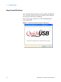
Step 1: Please open “setup.exe” at CD for installing Bitwise
System Quick USB.
Figure 2-1 Bitwise System Quick Installation USB Interface
2-2
E6198B Switch/Load Unit Software Manual
2
Installing The Driver
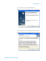
Step 2: Click Next to start InstallShield Wizard
Figure 2-2 Bitwise System Quick USB Installation Interface Continue..
Step 3: Accept the term of license agreement and click Next
Figure 2-3 Bitwise System Quick USB Installation Interface Continue...
E6198B Switch/Load Unit Software Manual
2-3
2
Installing The Driver
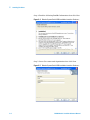
Step 4: Read the following ReadMe Information then click Next
Figure 2-4 Bitwise System Quick USB Installation Interface Continue...
Step 5: Insert User name and Organization then click Next
Figure 2-5 Bitwise System Quick USB Installation Interface Continue...
2-4
E6198B Switch/Load Unit Software Manual
Installing The Driver
2
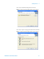
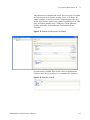
Step 6: Choose installation folder path then click Next
Figure 2-6 Bitwise System Quick USB Installation Interface Continue...
Step 7: Select “Typical” setup type (Recommend) then click Next
Figure 2-7 Bitwise System Quick USB Installation Interface Continue...
E6198B Switch/Load Unit Software Manual
2-5
2
Installing The Driver
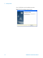
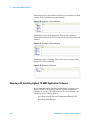
Step 8: Installation is ready to start, click Install to proceed.
Figure 2-8 Bitwise System Quick USB Installation Interface Continue...
Step 9: Click Finish to exit Bitwise Quick USB Installation
After installing Bitwise Quick USB successfully, the following is
to install SLU Handler DLL.
Step 1: Click Next to process InstallShield Wizard
Figure 2-9 SLU Plus Installation Interface
2-6
E6198B Switch/Load Unit Software Manual
Installing The Driver
2
Step 2: Choose install folder path then click Next
Figure 2-10 SLU Plus Installation Interface Continue...
Step 3: Install if ready to start installation
Figure 2-11 SLU Plus Installation Interface Continue...
E6198B Switch/Load Unit Software Manual
2-7
2
Installing The Driver
Step 4: Click Finish to exit the installation procedure
Figure 2-12 SLU Plus Installation Interface Continue...
2-8
E6198B Switch/Load Unit Software Manual
Agilent TS-5000 Series Automotive Functional Test System
E6198B Switch/Load Unit Software Manual
3
Programming With TestExec SL
This chapter describes how to program with TestExec SL to call
Agilent E6198B Swith/Load Unit, Load Cards and Pin Matrix
Module.
• Procedure of Programming TestExec SL Specific Handler
• Advantage Of Installing Agilent TS-5000 Application
Software
Agilent Technologies
3-1
3
Programming With TestExec SL
Procedure of Programming TestExec SL Specific Handler
Start With System Configuration Editor
To find out more about the System Configuration Editor, please
refer to the section under "Advantage Of Installing Agilent
TS-5000 Application Software". System Configuration Editor
version 6.0.2 should be installed before use with TestExec SL.
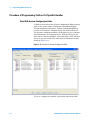
The System Configuration Editor (SCE) allows you to configure
system hardware and topology layers. With the SCE, you can
add, remove, and edit modules , wires and aliases. SCE will auto
detect on system to find SLU, load cards and instruments like
shown at Figure 3-13.
Figure 3-13 Interface of System Configuration Editor
To see or configure the module, just double click the module.
3-2
E6198B Switch/Load Unit Software Manual
Programming With TestExec SL
3
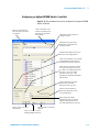
Configuring an Agilent E6198B Switch/Load Unit
Figure 3-14 The parameters that can be configured of an Agilent E6198B
Switch/Load Unit.
Name of switch /load unit.
This is the name referenced
in a testplan
Click on checkbox, if not
checked, to enable switch /
load unit to be accessible
from testplans
Description of switch /load unit.
Change if needed.
Descriptive keyword to aid in
finding the switch /load box in
the system.ust file
Parameter block data for the switch /
load unit. (See example below .)
Click on the checkbox, if not checked ,
to automatically generate the wires
and aliases for the switch /load unit.
Show the ICA connection for either
the Test System Interface ICA type
(TC, HP, CC), the Mass Interconnect
ICA type (1-21) or the L2000
Interconnect ICA type (1-25),
depending on what System Database
Files are used .
Click on checkbox to generate
optional wires (for Mass
Interconnect ICA type only )
Selects connector number to
where load channels are wired
(see example below )
Show starting pin number ,
dependent on what ICA is used .
Field is usually grayed out since
this value depends on the ICA type
Click on “OK” to save the
load card data
Click on “Help” to select this
help topic
Click on “Cancel” to cancel
changing/adding a load card
E6198B Switch/Load Unit Software Manual
3-3
3
Programming With TestExec SL
Example of a Switch/Load Unit Parameter Block Data Values
Table 3-1 Typical values in a Parameter Block.
Name
Value
Description
Device ID
E6198B
Instrument Identifier, usually the model number of the
Switch/Load Unit.
SBIOMode
0
Specifies the I/O method used to communicate the
switchBox.
E6198B: 8 for USB.
Load Box#
0
The number of the Switch/Load Unit. A number “0”
indicates the first Switch/Load Unit, and so on.
E6198B: Load Box Number (0-7)
Open Collector
Digital
0
Specifies the reset value for the Open Collector Digital
Output Port of the Switch/Load Unit.
Spare Digital
Output Reset Value
0
Specifies the reset value for the Spare Digital Output
Port of the Switch/Load Unit.
DAC Port #0
0.0
Specifies the reset voltage of the Digital-to-Analog
Converter Port #0 (first port) of the Switch/Load Unit.
DAC Port #0 Gain
1.0
Specifies the gain multiplier of the Digital-to-Analog
Converter Port #0 (first port) of the Switch/Load Unit.
DAC Port #0 Offset
0.0
Specifies the offset voltage of the Digital-to-Analog
Converter Port #0 (first port) of the Switch/Load Unit.
DAC Port #1
0.0
Specifies the reset voltage of the Digital-to-Analog
Converter Port #1 (second port) of the Switch/Load Unit.
DAC Port #1 Gain
1.0
Specifies the gain multiplier of the Digital-to-Analog
Converter Port #1 (second port) of the Switch/Load Unit.
DAC Port #1 Offset
0.0
Specifies the offset voltage of the Digital-to-Analog
Converter Port #1 (second port) of the Switch/Load Unit.
InGlobalReset
1
Include in global reset (0=Not in global reset)
3-4
E6198B Switch/Load Unit Software Manual
3
Programming With TestExec SL
Example of a Switch/Load Unit Wiring Configuration Values
Table 3-2 Typical configuration values. The configurations are generated when selecting the “Generate Wire and
Aliases” checkbox.
Name
Value
Description
ICA Slot
1
The designation for the ICA connector type or slot number to which
the load cards are to be wired. For the Test System Interface ICA
type, the designations are: "TC" (Test Connector), "Agilent" (High
Power), or "CC" (Custom Connector). For the Mass Interconnect ICA
type, the slot number designations are: 1 to 21 (i.e., slot numbers of
the Mass Interconnect).
For the L2000 Interconnect ICA type, the slot number designations
are: 1 to 26 (i.e. slot numbers of the L2000 Interconnect).
Connector
1
The connector number for the Test System Interface ICA type are
either 1 or 2. The connector number for the Mass Interconnect ICA
type are either A or B.
The connector number for the L2000 Interconnect ICA type is only
A.
Starting Pin
2
For the Test System Interface ICA type, the starting pin number for
the TCx connector may be "K1" where "K" is the Row value and "1" is
the column value; other connectors have different values. This field
is usually grayed out since these values are already set by the values
in the selected System Database Files.
E6198B Switch/Load Unit Software Manual
3-5
3
Programming With TestExec SL
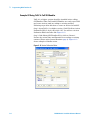
Example Of Using TxSL To Call SLUHandler
TxSL 6.1 or higher version should be installed before calling
SLUHandler. When TxSL and SLUHandler are ready, open TxSL
and create Action(.umd) according to existing routines.
Following steps show that how to create an Action for InitSLU.
Step 1: Open TxSL 6.1 or higher version. Click File>New>Action
Defination>DLL(C Style) then click ‘OK’. You will see a Action
Defination Editor interface like Figure 3-15.
Step 2: Link library(SLUHandler.dll) by click on ‘Browse’.
Declare the action name and Parameters according to existing
routines (Please refer General Routines page 4). Figure 3-15
shows example of InitSlu action.
Figure 3-15 Action Defination Editor
3-6
E6198B Switch/Load Unit Software Manual
3
Programming With TestExec SL
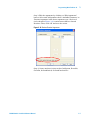
Step 3: Edit the arguments by clicking on “Edit Arguments”
button. Select and Add paramter from ‘Available Paramters’ to
‘Routine Arguments’ and choose argument type. Check red
circle shown in Figure 3-16, routine must same as General
Routines. Then, click ‘OK’ and save the action.
Figure 3-16 Declare Routine Arguments
Step 4: Create anothers Action such as InitSystem, ResetSlu,
CloseSlu, SetLoadSwitch, GetLoadCard and etc.
E6198B Switch/Load Unit Software Manual
3-7
3
Programming With TestExec SL
Step 5: Add Dynamic Link Library directory by clicking
Options>System Options>Search Paths. Choose Dynamic Link
Libraries and add folder path as shown in Figure 3-17.
Figure 3-17 Dynamic Link Library Path
1
2
3-8
E6198B Switch/Load Unit Software Manual
Programming With TestExec SL
3
After all actions is defined and saved. You can create a testplan
and use all actions for further testing. Figure 3-18 shows one
simple example to load a load card’s switching path. The first
action must declare connectivity either via parallel port or USB
port (SetUSB=0-parallel port; 1-USB port). Then, following
actions are InitSlu, SetLoadSwitch, GetLoadSwitch and
CloseSlu.
Figure 3-18 Example of Calling Load Card Testplan
Second action is InitSlu. This action is used to initialize the
Switch/Load Unit. Set boxNr as ‘0’ to initalize SLU number 1.
Figure 3-19 Parameter of InitSlu
E6198B Switch/Load Unit Software Manual
3-9
3
Programming With TestExec SL
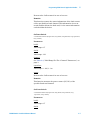
Following action is SetLoadSwitch. This action actuates the load
contact of the specified load card channel.
Figure 3-20 Parameter of SetLoadSwitch
Following action is GetLoadSwitch. This action returns the
status information of the load contact of the specified load card
channel.
Figure 3-21 Parameter of GetLoadSwitch
Following action is CloseSlu. This action closes the previously
initialized Switch/Load Unit.
Figure 3-22 Parameter of CloseSlu
Advantage Of Installing Agilent TS-5000 Application Software
We recommend Agilent TS-5000 System users to install to use
Agilent TestExec SL together with the TS-5000 Application
Software to test the Unit Under Test(UUT). Users will have the
advantage of two features from it:• Auto Detection By System Configuration Editor(SCE)
• Switching Path Manager
3-10
E6198B Switch/Load Unit Software Manual
Programming With TestExec SL
NOTE
3
Agilent TS-5000 Application Software is not included on Agilent
E6198B Driver Installation. The TS-5000 Application Software is
available separately from Agilent.
E6198B Switch/Load Unit Software Manual
3-11
3
Programming With TestExec SL
Auto Detection By System Configuration Editor(SCE)
This editor can auto-detect supporting GPIB, VXI, LXI and USB
instruments, Pin Matrix Modules, and/or load cards. It can also
be used to add new modules/instruments or delete old
modules/instruments to/from the system.ust file. (Please refer
“TS-5000 System Software Manual” for more detail). Figure 3-13
shows the interface of System Configuration Editor (SCE).
Switching Path Manager
Switching actions make connections from the instrument and
loads to the Unit Under Test. These actions are internal to
Agilent TestExec SL. The switching information in these actions
are determined by the data in the 'system.ust' file and the
user-generated fixture.ust and uut.ust files. Figure 3-23 shows
how to add switching on TestExec SL.
Figure 3-23 Switching Interface of TestExec SL
Click here to add
switching path
3-12
E6198B Switch/Load Unit Software Manual
Programming With TestExec SL
3
Click on switching path button on Parameters for “Switching” to
select which switching path for your test. Figure 3-24 shows
how to add switching path for a load card.
Figure 3-24 Interface of Switching Path for Load Card
E6198B Switch/Load Unit Software Manual
3-13
3
Programming With TestExec SL
THIS PAGE IS INTENTIONALLY LEFT BLANK.
3-14
E6198B Switch/Load Unit Software Manual
Agilent TS-5000 Series Automotive Functional Test System
E6198B Switch/Load Unit Software Manual
4
Programming With Generic Application
Handler
This chapter provides guidelines for programming a generic
handler in a Windows environment. The chapter contains the
following sections:
• Available Function Calls
• Applicable Function Calls vs. Load Card Models
• Valid Ranges For Load, Power And Sense Channels Vs. Load
Card Models
• General Routines
• Activate Load Card Relays
• Digital IO and DAC Control
• Error Codes
• Example Of Using Generic Handler
Agilent Technologies
4-1
4
Programming With Generic Application Handler
Available Function Calls
Following sub chapters give an overview of:
• Applicable funtion calls vs Load Card Models
• Valid ranges for Load, Power and Sense channels vs Load
Card Models
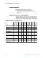
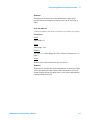
Applicable Function Calls vs. Load Card Models
Following table gives an overview of the applicable function
calls for a Load Card. Models which are not supported will
return with the error code-2 (LOAD_CARD_UNSUPPORTED)
4-2
InitSystem
X
InitSlu
X
ResetSlu
X
CloseSlu
X
N9379A
N9378A
N9377A
Z2080A
E6178B
E6177A
E6176A
E6175A
E6198A
Table 4-3 Overview of The Applicable Function Calls
SetLoadSwitch
X
X
X
X
X
X
X
X
GetLoadSwitch
X
X
X
X
X
X
X
X
SetPowerSwitch
X
X
X
X
X
X
GetPowerSwitch
X
X
X
X
X
X
SetCurrentSense
X
X
X
X
GetCurrentSense
X
X
X
X
SetDacVoltage
X
GetDacVoltage
X
E6198B Switch/Load Unit Software Manual
4
Programming With Generic Application Handler
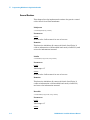
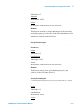
Valid Ranges For Load, Power And Sense Channels Vs. Load Card Models
Following tables shows the valid range for the “channel”
parameters of the mentioned calls.
Table 4-4 Valid Range For The “Channel” Parameters
E6175
A
E6176
A
E6177
A
E6178
B
Z2080
A
N9377
A
N9378
A
N9379
A
SetLoadSwitch
1-8
1-16
1-24
1-8
1-16
*
*
*
GetLoadSwitch
1-8
1-16
1-24
1-8
1-16
*
*
*
SetPowerSwitch
1-8
1-16
1-24
1-16
1-24
1-48
GetPowerSwitch
1-8
1-16
1-24
1-16
1-24
1-48
SetCurrentSense
1-8
1-16
1-8
**
GetCurrentSense
1-8
1-16
1-8
**
* For the Dual- and Quad-Load Modules there is a different numbering scheme for “channel” parameter of ther LoadSwitch routine:
N9377A: [ch]chld (channelNr+loadNr) where channel number (ch) can range from 1-16 and load number (ld) can range from 1-2
N9378A: [ch]chld (channelNr+loadNr) where channel number (ch) can range from 1-24 and load number (ld) can range from 1-4
N9379A: [ch]chld (channelNr+loadNr) where channel number (ch) can range from 1-48 and load number (ld) can range from 1-2
** For the N9377A Model there is an additional differential amplifier integrated for the current sense measuremnt. By adding 128 to the
relay channel number the differential amplifier will be switched on. So the “channel” parameter can range between 1-16 and 129-144.
E6198B Switch/Load Unit Software Manual
4-3
4
Programming With Generic Application Handler
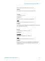
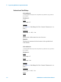
General Routines
This chapter lists the implemented routines for generic control
of the Switch Load Unit mainframe.
InitSystem
void InitSystem(long *status)
Parameters
status
Return value. Call returns 0 in case of success.
Remarks
This function initializes all connected Switch Load Units. It
collects information of all installed load cards (of all SLUs) and
stores the information internal.
InitSlu
void InitSlu (long boxNr, long*status)
Parameters
boxNr
Valid range: 0-7
status
Return value. Call returns 0 in case of success.
Remarks
This function initializes all connected Switch Load Units. It
conllects information of all installed load cards (of all SLUs)
and stores the information internal.
ResetSlu
void ResetSlu (long boxNr, long *status)
Parameters
boxNr
Valid range: 0-7
status
4-4
E6198B Switch/Load Unit Software Manual
Programming With Generic Application Handler
4
Return value. Call returns 0 in case of success.
Remarks
This function rest the specified Switch Load Units.
CloseSlu
void CloseSlu (long *status)
Parameters
This function does not contain any parameters.
status
Return value. Call returns 0 in case of success.
Remarks
This function closes all previously initialized SLUs and releases
the cached data in the driver.
SetUSB
void SetUSB (long vl_USBFlag, long *status)
Parameters
vl_USBFlag
Valid Range: 0-parallel port, 1-USB port
status
Return value. Call returns 0 in case of success.
Remarks
This function will select either parallel port or USB port for
connectivity. It is backward compatible with E6218A Mini
Switch\Load Unit.
E6198B Switch/Load Unit Software Manual
4-5
4
Programming With Generic Application Handler
Activate Load Card Relays
SetLoadSwitch
void SetLoadSwitch (long boxNr, long slotNr, long channel, long openClose,
long *status)
Parameters
boxNr
Valid range: 0-7
channel
See Table 4-4, “Valid Range For The “Channel” Parameters,” on
page 3.
openClose
Valid range : 0 - Off, 1 - On
status
Return value. Call returns 0 in case of success.
Remarks
This function actuates the load contact of the specified load
card channel.
GetLoadSwitch
void GetLoadSwitch (long boxNr, long slotNr, long channel, long *openClose,
long *status)
Parameters
boxNr
Valid range: 0-7
slotNr
Valid range: 1-21
channel
See Table 4-4, “Valid Range For The “Channel” Parameters,” on
page 3.
openClose
Valid range: 0 - Off, 1 - On
status
4-6
E6198B Switch/Load Unit Software Manual
4
Programming With Generic Application Handler
Return value. Call returns 0 in case of success.
Remarks
This function returns the status information of the load contact
of the specified load card channel. This information is not an
actual read back from the load card, it’s the status information
cached within the driver.
SetPowerSwitch
void SetPowerSwitch (long boxNr, long slotNr, long channel, long openClose,
long *status)
Parameters
boxNr
Valid range: 0-7
slotNr
Valid range: 1-21
channel
See Table 4-4, “Valid Range For The “Channel” Parameters,” on
page 3.
openClose
Valid range: 0 - Off, 1 - On
status
Return value. Call returns 0 in case of success.
Remarks
This function actuates the power contact (NC/NO) of the
specified load card channel.
GetPowerSwitch
void GetPowerSwitch (long boxNr, long slotNr, long channel, long
*openClose, long *status)
Parameters
boxNr
Valid range: 0-7
slotNr
E6198B Switch/Load Unit Software Manual
4-7
4
Programming With Generic Application Handler
Valid range: 1-21
channel
See Table 4-4, “Valid Range For The “Channel” Parameters,” on
page 3.
openClose
Valid range: 0 - Off, 1 - On
status
Return value. Call returns 0 in case of success.
Remarks
This function returns the status information of the power
contact of the specified load card channel. This information is
not an actual read back from the load card, it’s the status
information cached within the driver.
SetCurrentSense
void SetCurrentSense (long boxNr, long slotNr, long channel, long *status)
Parameters
boxNr
Valid range: 0-7
slotNr
Valid range: 1-21
channel
See Table 4-4, “Valid Range For The “Channel” Parameters,” on
page 3.
Note:
• Only one sense-channel in the system can be set at a time - so
after the current measurement the actuated sense relays
must be “unlocked” by calling the routine with the channel
paramter set to 0.
• The E6176A is a special model which shares oen sense
resistor for two adjacent load channels. (see E6198B Switch
Load Unit User’s Manual.pdf)
status
Return value. Call returns 0 in case of success.
4-8
E6198B Switch/Load Unit Software Manual
4
Programming With Generic Application Handler
Remarks
This function actuates the sense multiplexer relays of the
specified load card channel (only one pair can be closed at a
time).
GetCurrentSense
void GetCurrentSense (long boxNr, long slotNr, long *channel, long *status)
Parameters
boxNr
Valid range: 0-7
slotNr
Valid range: 1-21
channel
See Table 4-4, “Valid Range For The “Channel” Parameters,” on
page 3.
status
Return value. Call returns 0 in case of success.
Remarks
This function returns the status information of the sense relays
of the specified load card channel. This information is not an
actual read back from the load card, it’s the status information
cached within the driver.
E6198B Switch/Load Unit Software Manual
4-9
4
Programming With Generic Application Handler
Digital IO and DAC Control
GetDigitalInput
void GetDigitalInput (long boxNr, long *digitalIn, long *status)
Parameters
boxNr
Valid range: 0-7
digitalIn
Return value: 0-255
status
Return value. Call returns 0 in case of success.
Remarks
This function reads the digital input port of the SLU frame (Bit
0-7).
SetDigitalOutput
void SetDigitalOutput (long boxNr, long digitalOut, long *status)
Parameters
boxNr
Valid range: 0-7
digitalOut
Valid range: 0-255
status
Return value. Call returns 0 in case of success.
Remarks
This function writes to the digital output port of the SLU frame
(Bit 0-7)
GetDigitalOutput
void GetDigitalOutput (long boxNr, long *digitalOut, long *status)
Parameters
boxNr
4-10
E6198B Switch/Load Unit Software Manual
4
Programming With Generic Application Handler
Valid range: 0-7
digitalOut
Return value: 0-255
status
Return value. Call returns 0 in case of success.
Remarks
This function returns the status information of the previously
set digital output port of the SLU frame. This information is not
an actual read back from the load card, it’s the status
information cached within the driver.
SetOpenDrainOutput
void SetOpenDrainOutput (long boxNr, long openDrainOut, long *status)
Parameters
boxNr
Valid range: 0-7
openDrainOut
Valid range: 0-255
status
Return value. Call returns 0 in case of success.
Remarks
This function writes to the open drain output port (open
collector) of the SLU frame (Bit 0-7).
GetOpenDrainOutput
void GetOpenDrainOutput (long boxNr, long *openDrainOut, long *status)
Parameters
boxNr
Valid range: 0-7
openDrainOut
Return value: 0-255
status
E6198B Switch/Load Unit Software Manual
4-11
4
Programming With Generic Application Handler
Return value. Call returns 0 in case of success.
Remarks
This function returns the status information of the previously
set open drain output port of the SLU frame. This information is
not an actual read back from the load card, it’s the status
information cached within the driver.
SetDacVoltage
void SetDacVoltage (long boxNr, long dac, double volts, long *status)
Parameters
boxNr
Valid range: 0-7
Dac
Valid range: 1 DAC1 2 DAC2
volts
Valid range: ±16V
status
Return value. Call returns 0 in case of success.
Remarks
This function writes to the specified DAC output of the SLU
frame.
GetDacVoltage
void GetDacVoltage (long boxNr, long dac, double *volts, long *status)
Parameters
boxNr
Valid range: 0-7
dac
Valid range: 1 DAC1 2 DAC2
volts
Return value: ±16V
status
4-12
E6198B Switch/Load Unit Software Manual
4
Programming With Generic Application Handler
Return value. Call returns 0 in case of success.
Remarks
This function returns the status information of the previously
set DAC output voltage of the SLU frame. This information is
not an actual read back from the load card, it’s the status
information cached within the driver.
E6198B Switch/Load Unit Software Manual
4-13
4
Programming With Generic Application Handler
Error Codes
The Error Codes representing the feedback message from
system. All Error Codes contain in system are shown in table
below:
Table 4-5 Error Codes
Code
4-14
Description
0
Success
-1
Error
-2
Unsupported call (e.g. unsupported functionality for the selected load card)
see Table 4-4, “Valid Range For The “Channel” Parameters,” on page 3.
-3
Range – Parameter value was out of valid range.
-4
Timeout – Function was not able to complete within given time period.
-5
Vport – Not able to access the controllers parallel port.
-6
Shared Memory – Error accessing/not allocated shared memory section.
-7
Timer handle – Error creating handle for timer function.
-8
Memory – Error creating new instance for module.
-9
Sense lock – Not able to access sense-bus exclusive.
E6198B Switch/Load Unit Software Manual
4
Programming With Generic Application Handler
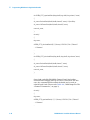
Example Of Using Generic Handler
Like all instruments, the Switch Load Unit should go through an
initialization process.. InitSlu(boxNr) is initial Switch Load Unit
function, boxNr is number of SLU (valid 0-7). If status return 0
initialization is a success.
int main ()
{
long return;
status = e6198b_init(0, &return) ; //Initial SLU Number 0. Valid 0-7
…
// Command
…
}
int e6198b_init(long boxNr, long *status)
{
slu_status = InitSlu(boxNr, *status);
return slu_status;
}
To close the contact for a specified load card channel, for
example E6176A 16-Channel Load Card, the following command
may be used:
SetLoadSwitch(boxNr,long slotNr, long channel, long openClose,
long *status) and set power command, SetPowerSwitch(boxNr,
long slotNr, long channel, long openClose, long *status). Set '0'
into long openClose to open Relays; set '1' is to close Relays.
int main ()
{
long return;
e6198b_6176_openLoadSwitch(0,1,1, &return); //Call SLU 0, Slot 1, Channel 1
…// Command
…
}
E6198B Switch/Load Unit Software Manual
4-15
4
Programming With Generic Application Handler
int e6198b_6176_openLoadSwitch(long boxNr,long slotNr, long channel, *status)
{
slu_status=SetLoadSwitch(boxNr,slotNr,channel,0,*status);// Open Relay
slu_status=SetPowerSwitch(boxNr,slotNr,channel,0,*status);
return slu_status;
}
int main()
{
long return;
e6198b_6176_closeLoadSwitch(0,1,1,&return);//Call SLU 0, Slot 1, Channel 1
…// Command
…
}
int e6198b_6176_closeLoadSwitch(long boxNr, long slotNr, long channel,*status)
{
slu_status=SetLoadSwitch(boxNr,slotNr,channel,1,*status);
slu_status=SetPowerSwitch(boxNr,slotNr,channel,1,*status);
return slu_status;
}
Some load cards like E6198B 8-Channel Load Card utilize
external Power Supply directly to Power Connection. For this
case, the command SetPowerSwitch should not be used on
related Load Card. (Please refer Table 4-4, “Valid Range For The
“Channel” Parameters,” on page 3)
int main()
{
long return;
e6198b_6178_openLoadSwitch( 0, 1, 1,&return);//Call SLU 0, Slot 1, Channel 1
…// Command
…
4-16
E6198B Switch/Load Unit Software Manual
4
Programming With Generic Application Handler
}
int e6198b_6178_openLoadSwitch(long boxNr,long slotNr, long channel,*status)
{
slu_status=SetLoadSwitch(boxNr,slotNr,channel,0,*status);
return slu_status;
}
int main()
{
long return;
e6198b_6178_closeLoadSwitch( 0, 1, 1,&return);//Call SLU 0, Slot 1, Channel 1
…// Command
…
}
int e6198b_6178_closeLoadSwitch(long boxNr, long slotNr, long channel,*status)
{
slu_status=SetLoadSwitch(boxNr,slotNr,channel,1,*status);
return slu_status;
}
ResetSlu(boxNr) initializes all connected Switch Load Unit. It
collects information of all installed load cards (of all SLUs) and
stores the information internal.
int reset()
{
long return;
e6198b_reset(0,&return);
return 0;
}
int e6198b_reset(long boxNr,*status)
{
slu_status=ResetSlu(boxNr,*status);
E6198B Switch/Load Unit Software Manual
4-17
4
Programming With Generic Application Handler
return slu_status;
}
CloseSlu() function closes all previously initialized SLUs and
releases the cached data in the driver.
int close()
{
long return;
e6198b_closeSLU(&return);
return 0;
}
int e6198b_closeSLU(*status)
{
slu_status=CloseSlu(*status);
return slu_status;
}
SetCurrentSense(boxNr,slotNr,channel,*status) actuates the
sense multiplexer relays of the specified load card channel (only
one pair can be closed at a time, so after the current
measurement the actuated sense relays must be "unlocked" by
calling the routine with the channel parameter set to 0).
int main()
{
long return;
e6198b_closeCurrentSense(0,1,1,&return);
…
…
}
int e6198b_closeCurrentSense(long boxNr, long slotNr, long channel,*status)
{
slu_status=SetCurrentSense(boxNr, slotNr, channel,*status);
return slu_status;
4-18
E6198B Switch/Load Unit Software Manual
Programming With Generic Application Handler
4
}
int main()
{
long return;
e6198b_openCurrentSense(0, 1,&return);
…
…
}
int e6198b_openCurrentSense(long boxNr, long slotNr,*status)
{
slu_status=SetCurrentSense(boxNr, slotNr, 0,*status); //channel=0 to unlock
sense
return slu_status;
}
E6198B Switch/Load Unit Software Manual
4-19
4
Programming With Generic Application Handler
THIS PAGE IS INTENTIONALLY LEFT BLANK.
4-20
E6198B Switch/Load Unit Software Manual
Agilent TS-5000 Series Automotive Functional Test System
E6198B Switch/Load Unit Software Manual
Glossary Of Terms
Agilent Technologies
G-1
G
Glossary Of Terms
• Aliases
Alternate names for nodes, wires, or other aliases. The
names are descriptive in nature to easily identify the node.
For example, the alias for "ISrcHi" references a wire
connecting the system instrument multiplexer to the Digital
Multimeter (DMM) node for its positive current source.
• DLL
Dynamic Link Library.
• Load Card
A C-sized card designed to fit in the Switch/Load Unit that
provides switching for the various loads, and provisions for
either internal load mounting, or connections for external
load mounting. Load cards provide a two level card ID; card
type, and load configuration ID.
• SCE
System Configuration Editor.
• SLU
Switch/Load Unit.
• Wires
Wires connect two or more nodes. In some cases, wire names
are the same aliases used for nodes. For example, the alias
called "DVMIsrcHi" might be used for the wire name that
connects to that node.
G-2
E6198B Switch/Load Unit Software Manual