1
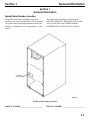
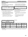
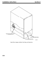
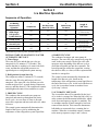
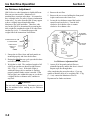
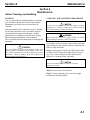
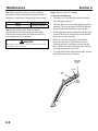
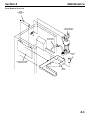
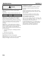
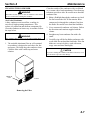
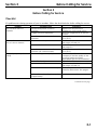
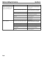
QM20 Series
Ice Machine
Installation,
Use and Care,
and Service Manual
Thank you for selecting a Manitowoc Ice Machine, the dependability leader in ice making equipment and
related products. With proper care and maintenance, your new Manitowoc Ice Machine will provide you with
many years of reliable and economical performance.
We reserve the right to make product improvements at any time.
Specifications and design are subject to change without notice.
Part Number 000001770
10/06
Safety Notices
Procedural Notices
When using or servicing a QM Series Ice Machine,
be sure to pay close attention to the safety notices in
this manual. Disregarding the notices may lead to
serious injury and/or damage to the ice machine.
When using or servicing a QM Series Ice Machine,
be sure to read the procedural notices in this manual.
These notices supply helpful and important
information.
Throughout this manual, you will see the following
types of safety notices:
Throughout this manual, you will see the following
types of procedural notices:
WARNING
Text in a Warning box alerts you to a potential
personal injury situation. Be sure to read the
Warning statement, and then proceed carefully.
CAUTION
Text in a Caution box alerts you to a situation in
which you could damage the ice machine. Be sure
to read the Caution statement, and then proceed
carefully.
CAUTION
Proper care and maintenance are essential for
maximum ice production and trouble-free operation
of your Manitowoc Ice Machine.
Important
Important boxes serve two functions.
They call the operator’s attention to important
information.
They also provide the service technician with
information that may help perform a procedure
more efficiently. Disregarding this information may
slow down the work.
NOTE: Text set off as a Note provides you with
simple, but useful, extra information.
This manual covers the following model numbers:
Self-Contained Air-Cooled: QM20A
Read and understand this manual. It contains
valuable care and maintenance information. If you
encounter problems not covered by this manual,
feel free to contact Manitowoc Ice, Inc. We will be
happy to provide assistance.
Warning
Personal Injury Potential
Do not operate equipment that has been,
misused, abused, neglected, damaged, or
altered/modified from that of original
manufactured specifications.
Table of Contents
Table of Contents
Section 1 - General Information
Model/Serial Number Location ...................................................................................................................... 1-1
Owner Warranty Registration Card.............................................................................................................. 1-2
Warranty Coverage ......................................................................................................................................... 1-2
Section 2 - Installation Instructions
Dimensions........................................................................................................................................................ 2-1
Location of Ice Machine .................................................................................................................................. 2-2
Leveling the Ice Machine................................................................................................................................. 2-2
Electrical Service.............................................................................................................................................. 2-3
Water Service/Drains....................................................................................................................................... 2-5
Section 3 - Ice Machine Operation
Sequence of Operation..................................................................................................................................... 3-1
Ice Thickness Adjustment ............................................................................................................................... 3-2
Section 4 - Maintenance
Interior cleaning and Sanitizing ..................................................................................................................... 4-1
Cleaning and Sanitizing Procedure................................................................................................................ 4-1
Exterior Cleaning............................................................................................................................................. 4-6
Cleaning the Condenser .................................................................................................................................. 4-7
Removal from Service/Winterization............................................................................................................. 4-8
Section 5 - Before Calling for Service
Checklist............................................................................................................................................................ 5-1
i
Table of Contents
THIS PAGE INTENTIONALLY LEFT BLANK
ii
Section 1
General Information
Section 1
General Information
Model/Serial Number Location
Record the model and serial number of your ice
machine in the space provided below. These numbers
are required when requesting information from your
Manitowoc distributor, service representative, or the
factory.
The model and serial number are listed on the
OWNER WARRANTY REGISTRATION CARD.
They are also listed on the MODEL/SERIAL
NUMBER DECAL affixed to the ice machine.
MODEL AND
SERIAL NUMBER
SV1702
Model/Serial Number Location
MODEL NUMBER: ________________________
SERIAL NUMBER: _________________________
1-1
General Information
Section 1
Owner Warranty Registration Card
GENERAL
The packet containing this manual also includes
warranty information. Warranty coverage begins the
day your new ice machine is installed.
Important
Complete and mail the OWNER WARRANTY
REGISTRATION CARD as soon as possible to
validate the installation date.
If you do not return your OWNER WARRANTY
REGISTRATION CARD, Manitowoc will use the
date of sale to the Manitowoc Distributor as the first
day of warranty coverage for your new ice machine.
Warranty Coverage
GENERAL
The following Warranty outline is provided for your
convenience. For a detailed explanation, read the
warranty bond shipped with each product.
Contact your local Manitowoc representative or
Manitowoc Ice, Inc. if you need further warranty
information.
Important
This product is intended exclusively for
commercial application. No warranty is extended
for personal, family, or household purposes..
PARTS
Manitowoc warrants the ice machine against defects
in materials and workmanship, under normal use
and service for three (3) years from the date of
original installation.
LABOR
Labor required to repair or replace defective
components is covered for three (3) years from the
date of original installation.
1-2
EXCLUSIONS
The following items are not included in the ice
machine’s warranty coverage:
1. Normal maintenance, adjustments and cleaning
as outlined in the Owner/Operator Use and Care
Guide.
2. Repairs due to unauthorized modifications to the
ice machine or the use of non-standard parts
without prior written approval Manitowoc Ice,
Inc.
3. Damage caused by improper installation of the
ice machine, electrical supply, water supply or
drainage, or damage caused by floods, storms,
or other acts of God.
4. Premium labor rates due to holidays, overtime,
etc.; travel time; flat rate service call charges;
mileage and miscellaneous tools and material
charges not listed on the payment schedule.
Additional labor charges resulting from the
inaccessibility of the ice machine are also
excluded.
5. Parts or assemblies subjected to misuse, abuse,
neglect or accidents.
6. Damage or problems caused by installation,
cleaning and/or maintenance procedures
inconsistent with the technical instructions
provided in the Installation Manual and the
Owner/Operator Use and Care Guide.
AUTHORIZED WARRANTY SERVICE
To comply with the provisions of the warranty, a
refrigeration service company, qualified and
authorized by a Manitowoc distributor, or a
Contracted Service Representative must perform the
warranty repair.
NOTE: If the dealer the ice machine was purchased
from is not authorized to perform warranty service,
contact the Manitowoc distributor or Manitowoc
Ice, Inc. for the name of the nearest authorized
service representative.
Service Calls
If you have followed the procedures listed in
Section 5 of this manual, and the ice machine still
does not perform properly, call your authorized
service company.
Section 2
Installation Instructions
Section 2
Installation Instructions
Dimensions
38.10 cm
(15.00”)
76.20 cm
(30.00”)
3.73 cm
(1.47”)
3.58 cm
(1.41”)
20.54 cm
(8.09”)
20.54 cm
(8.09”)
15.72 cm
(6.19”)
55.93 cm
(22.02”)
1.90 cm ± 0.63 cm
(0.75” ± 0.25”)
19.05 cm
(7.50”)
SV1717
2-1
Installation Instructions
Section 2
Location of Ice Machine
Leveling the Ice Machine
The location selected for the ice machine must meet
the following criteria. If any of these criteria are not
met, select another location.
After moving the ice machine into the installation
location, it must be leveled for proper operation.
Follow these steps to level the ice machine:
•
•
1. Check the level of the ice machine from front to
back and from side to side.
•
•
•
•
•
The location must be indoors.
The location must be free of airborne and other
contaminants.
The air temperature must be at least 10°C (50°F),
but must not exceed 40°C (110°F).
The location must not be near heat-generating
equipment or in direct sunlight.
The counter top (or other resting surface) must be
able to support 425 kg per square meter (0.6 lb.
per square inch).
The location must allow enough clearance for
water, drain, and electrical connections in the
rear of the ice machine.
The location must not obstruct air flow to any
portion of the front of the ice machine.
CAUTION
The ice machine must be protected if it will be
subjected to temperatures below 0°C (32°F).
Failure caused by exposure to freezing
temperatures is not covered by the warranty. See
“Removal from Service/Winterization” on page 48.
Top/Sides
Back
Self-Contained Air-Cooled
203 mm (5”)*
127 mm (5”)*
SV1704
Checking for Level
2. If the ice machine is not level, adjust the leveling
glides on each corner of the base of the ice
machine as necessary.
3. Check the level of the ice machine after each
adjustment of the leveling glides.
4. Repeat steps 2 and 3 until the ice machine is level
from front to back and from side to side.
NOTE: The ice machine may be built into a cabinet. There
is no minimum clearance requirement for the top or the
left and right sides of the ice machine
Ice Machine Heat of Rejection
Series
Ice Machine
QM20
Heat of Rejection*
Air Conditioning**
Peak
1450
2100
* B.T.U./Hour
** Because the heat of rejection varies during the ice making cycle, the
figure shown is an average.
Ice machines, like other refrigeration equipment,
reject heat through the condenser. It is helpful to
know the amount of heat rejected by the ice machine
when sizing air conditioning equipment where selfcontained air-cooled ice machines are installed.
2-2
Leveling Glide
SV1705
Section 2
Installation Instructions
Electrical Service
GENERAL
WARNING
All wiring must conform to local, state and national
codes.
WARNING
Never use an extension cord. If an outlet is not
within reach of the ice machine’s power cord, have
a proper amperage outlet wired closer to the ice
machine.
Voltage Phase
Cycle
230/50/1
115/60/1
Air-Cooled
Electrical Rating
0.3 KW / 1.5 Amps
0.4KW / 3.5 Amps
VOLTAGE
The maximum allowable voltage variation is ± 10%
of the rated voltage at ice machine start-up (when the
electrical load is highest).
WARNING
The ice machine must be grounded in accordance
with national and local electrical codes.
FUSE/CIRCUIT BREAKER
A separate fuse/circuit breaker must be provided for
each ice machine.
NOTE: A disconnect means must be provided for
field wiring.
ELECTRICAL RATING
The electrical rating is used to help select the wire
size of the electrical supply. The wire size (or gauge)
also depends on location, materials used, length of
run, etc., so it must be determined by a qualified
electrician.
FOR UNITED KINGDOM ONLY
As the colours of the wires in the mains lead of the
appliance may not correspond with the coloured markings
identifying the terminals in your plug, proceed as follows:
•
The wire which is coloured green and yellow must be
connected to the terminal in the plug which is marked
with the letter E or by the earth symbol , or
coloured green or green and yellow.
•
The wire coloured blue must be connected to the
terminal which is marked with the letter N or coloured
black.
•
The wire which is coloured brown must be connected
the terminal which is marked with the letter L or
coloured red.
2-3
Installation Instructions
Section 2
ELECTRICAL CORD STRAIN RELIEF
To prevent strain at the electrical connection inside
the ice machine, an electrical cord strain relief device
must be installed on the rear panel of the ice machine.
1. Disassemble the strain relief device into its three
components.
2. Install the cord holder through the opening in the
lower right corner of the rear panel of the ice
machine.
TERMINAL BLOCK WIRE CONNECTION
WARNING
Always disconnect power to the ice machine before
working on electrical circuitry.
After the electrical cord is installed in the strain relief
device, the cord must be connected to the terminal
block to supply power to the ice machine.
1. Remove two Phillips head screws to remove the
lower panel from the front of the ice machine.
2. Carefully reach into the ice machine and pull the
electrical cord forward to the terminal block.
3. Strip away enough insulation from the electrical
cord to allow for good electrical connections at
the terminal block .
RETAINING NUT
(BEHIND THE PANEL)
CORD
HOLDER
TERMINAL
BLOCK
ELECTRICAL
CORD
L1
COMPRESSION
NUT
ELECTRICAL
CORD
SV1706
N
GND
Strain Relief Installation
3. Hand-tighten the retaining nut onto the cord
holder from inside the ice machine rear panel.
4. Slide the compression nut over the electrical cord.
5. Feed about 1.5 m (5 ft.) of electrical cord through
the cord holder. (The extra cord will allow the
rear panel to be removed for future service.)
6. Hand-tighten the compression nut onto the cord
holder.
2-4
Terminal Block Connections
SV1707
4. Open the screw terminals on the terminal block.
5. Connect each wire in the electrical cord to the
appropriate screw terminal.
6. Carefully tighten the screws over the wire.
7. Tug lightly on each wire to be sure the
connections are secure.
Section 2
Installation Instructions
Water Service/Drains
WATER SUPPLY
Local water conditions may require treatment of the
water to inhibit scale formation, filter sediment, and
remove chlorine odor and taste.
Important
If you are installing a Manitowoc water filter
system, refer to the Installation Instructions
supplied with the filter system for ice making water
inlet connections.
Follow these guidelines to install water inlet lines:
•
•
•
Connect to potable water supply only.
Do not connect the ice machine to a hot water
supply. Be sure all hot water restrictors installed
for other equipment are working. (Check valves
on sink faucets, dishwashers, etc.)
If water pressure exceeds the maximum
recommended pressure, obtain a water pressure
regulator from your Manitowoc distributor.
•
•
Install a water shut-off valve for both the ice
making and condenser water lines (if applicable).
Insulate water lines to prevent condensation.
Important
The water inlet line is connected to the water valve.
This valve is located just behind the front panel of
the ice machine.
DRAIN CONNECTIONS
Follow these guidelines when installing drain lines to
prevent drain water from flowing back into the ice
machine and storage bin:
•
•
•
Drain lines must have a 2.5 cm (1 inch) drop per
1 meter (40 inches) of run, and must not create
traps.
The floor drain must be large enough to
accommodate drainage from all drains.
Insulate the bin drain line to prevent
condensation.
WATER SUPPLY AND DRAIN LINE SIZING/CONNECTIONS
CAUTION
Plumbing must conform to state and local codes.
Water
Temperature
Water
Pressure
Ice Machine
Fitting
Ice Making
Water Inlet
10°C (50°F) Min.1
30°C (86°F) Max.2
2.4 bar (35 psi) Min.1
6.2 bar (90 psi) Max.2
3/4” male hose
connection3
Ice Making/Bin
Water Drain
---
---
1.59 cm (5/8”)
inside diameter
flexible hose
Tubing Size Up to Ice
Machine Fitting
0.95 cm (3/8”)
minimum inside
diameter
1.59 cm (5/8”)
minimum inside
diameter
1
Min. = Minimum
Max. = Maximum
3
A 3/4” by 11-1/2 threads per inch to 14 threads per inch adapter is factory installed. Remove this adapter if 11-1/2 threads per inch
connection is desired.
2
2-5
Installation Instructions
Section 2
ROUTE ICE MAKING WATER INLET TUBING
THROUGH ICE MACHINE AND CONNECT
TO WATER INLET VALVE
ICE MAKING/BIN WATER DRAIN TUBING
1.59 cm (5/8”) MINIMUM INSIDE DIAMETER
ICE MAKING WATER INLET TUBING
0.95 cm (3/8”) MINIMUM INSIDE DIAMETER
SV1708
Typical Water Supply and Drain Line Sizing and Connections
2-8
Section 3
Ice Machine Operation
Section 3
Ice Machine Operation
Sequence of Operation
Ice Making
Sequence of
Operation
Start-Up1
1. Water Purge
2. Refrigeration
System Start-Up
1
1
Compressor
Control Board Relays
2
Hot Gas Valve
Water Fill Valve
3
Water Pump
Fan Motor
Length of
“ON” Time
Off
On
Off
2.9 Minutes
(175 Seconds)
On
On
Off
5 Seconds
3. Freeze Cycle
On
Off
On
4. Harvest Cycle
On
On
Off
5. Auto Shut-Off
Off
Off
Off
Automatically
determined
Automatically
determined
Until bin thermostat
re-closes
Initial Start-Up or Start-Up After Automatic Shut-Off
INITIAL START-UP OR START-UP AFTER
AUTOMATIC SHUT-OFF
1. Water Purge
The water fill valve and the hot gas valve are
energized for 2.9 minutes (175 seconds). This
ensures that the ice making cycle starts with fresh
water, and that the refrigerant pressures are
equalized prior to refrigeration system start-up.
2. Refrigeration System Start-Up
The compressor starts 2.9 minutes (175 seconds)
after the water fill valve and hot gas valve are
energized. (The water fill valve and hot gas valve
remain energized for 5 seconds during compressor
start-up, and then shut off.) The compressor remains
on throughout the entire freeze and harvest cycles.
3. FREEZE CYCLE
The condenser fan motor and water pump are
energized and remain on throughout the entire
freeze cycle. An even flow of water is directed
across the evaporator and into each cube cell, where
it freezes.
The control system automatically determines the
length of the freeze cycle by monitoring the
temperature of the refrigeration system liquid line.
4. HARVEST CYCLE
The condenser fan motor and water pump deenergize. The water fill valve energizes to purge the
water in the water trough. The hot gas valve also
energizes at the beginning of the harvest cycle to
divert hot refrigerant gas into the evaporator. The
hot refrigerant gas warms the evaporator, causing
the cubes to slide, as a sheet, off the evaporator and
into the ice storage bin.
The control system automatically determines the
length of the harvest cycle, based on the
temperature of the refrigeration system liquid line at
the end of the freeze cycle. At the end of the harvest
cycle, the ice machine returns to another freeze
cycle (step 3, above).
5. AUTOMATIC SHUT-OFF
The ice machine shut-off is controlled by the level
of ice in the ice storage bin. When the bin is full, ice
cubes contact the bin thermostat bulb holder, which
cools down and opens to stop the ice machine. The
ice machine remains off until enough ice has been
removed from the bin. This causes the thermostat
bulb holder to warm and close, restarting the ice
machine. When the ice machine restarts, it returns
to the start-up sequence (steps 1 and 2, above).
3-1
Ice Machine Operation
Section 3
Ice Thickness Adjustment
QM-20 dice ice cube formation is slightly different
from our previous models. Manitowoc ice
machines have a unique cube shape. It is normal to
have a dimple in the ice cube (a concave indentation
in the cube). Ice cubes from the QM-20 may appear
to have a slightly larger dimple than other
Manitowoc dice cube machines. Therefore, cube
size for the QM-20 is determined by measuring the
slab weight (the combined weight of all cubes from
one harvest cycle). To determine proper slab
weight follow the instructions listed below.
4. Remove the air filter.
5. Remove the two screws holding the front panel
in place and remove the front cover.
6. Locate the ice thickness control dial on the
control board (see below). Turn the dial
clockwise for a thicker cube or counter
clockwise for a thinner cube.
ICE THICKNESS
ADJUSTMENT DIAL
ICE BRIDGE SHOULD BE 1.5 MM
TO 3.2 MM THICKNESS
DIAL IS FACTORY
SET TO ZERO
A DIMPLE IN EACH
CUBE CELL IS
NORMAL
Correct Ice Bridge Thickness
1. Ensure the air filter, front, and back panels are
installed properly and close the bin door.
2. During the third harvest cycle open the bin door
and catch the entire slab of ice.
3. Weigh the ice slab. The combined weight of all
cubes from one harvest should weigh between
200 - 270g (7 - 9-oz). If the slab weight is
within this range, the ice machine is working
properly and no further action is needed. If the
slab weight is not within this range or you desire
a slightly thicker or thinner cube, continue to
step four.
WARNING
Do not touch electrical wires. Disconnect power to
the ice machine before making any ice thickness
adjustments.
3-2
sv1710
Ice Thickness Adjustment Dial
7. Assure all of the panels and air filter are
reinstalled properly and the bin door is closed.
Repeat steps one through three.
After completing the procedure above, if you are
unable to obtain a sheet of ice weighing 200 - 270g
(7 - 9-oz) contact the Manitowoc Service
Department for further assistance.
Section 4
Maintenance
Section 4
Maintenance
Interior Cleaning and Sanitizing
GENERAL
You are responsible for maintaining the ice machine
in accordance with the instructions in this manual.
Maintenance procedures are not covered by the
warranty.
Clean and sanitize the ice machine every six months
for efficient operation. If the ice machine requires
more frequent cleaning and sanitizing, consult a
qualified service company to test the water quality
and recommend appropriate water treatment.
The ice machine must be taken apart for cleaning and
sanitizing.
CAUTION
Use only Manitowoc approved Ice Machine Cleaner (part
number 94-0546-3) and Sanitizer (part number 94-0565-3). It
is a violation of Federal law to use these solutions in a manner
inconsistent with their labeling. Read and understand all
labels printed on bottles before use.
CLEANING AND SANITIZING PROCEDURE
CAUTION
Do not mix Ice Machine Cleaner and Sanitizer solutions
together. It is a violation of Federal law to use these solutions
in a manner inconsistent with their labeling.
WARNING
Wear rubber gloves and safety goggles (and/or face shield)
when handling Ice Machine Cleaner or Sanitizer.
Ice machine cleaner is used to remove lime scale and
mineral deposits. Ice machine sanitizer disinfects and
removes algae and slime.
Step 1 Set the toggle switch to the OFF position after
ice falls from the evaporator at the end of a Harvest
cycle. Or, set the switch to the OFF position and
allow the ice to melt off the evaporator.
CAUTION
Never use anything to force ice from the evaporator.
Damage may result.
Step 2 Remove all ice from the bin.
Step 3 To start a cleaning cycle, move the toggle
switch to the WASH position.
4-1
Maintenance
Section 4
Step 4 Wait until water flows over the evaporator
(about three minutes) then add the proper amount of
Manitowoc Ice Machine Cleaner to the water trough.
Model
QM20
Amount of Cleaner
30 ml (1 ounce)
Step 5 Wait until the clean cycle is complete
(approximately 45 minutes) then place the toggle
switch in the OFF position, disconnect power and
water supplies to the ice machine.
Step 6: Remove parts for cleaning.
A. Remove the Bin Door
• Grasp the rear of the bin door and pull bin door
forward approximately 5”.
•
Slide bin door to the rear while applying upward
pressure (The rear door pins will ride up into the
track slot and slide backward to the stop tab).
•
While applying pressure against the bin door pull
down on the rear of each bin door track until the
door pins clear the stop tabs.
•
Slide the rear door pins off the end and then
below the door track. Slide bin door forward
allowing the back of the door to lower into the
bin. Continue forward with the bin door until the
front pins bottom out in the track.
•
Lift right side of door until the front pins clear the
track, then remove door from bin.
WARNING
Disconnect electric power to the ice machine at the electric
switch box before proceeding.
PRESS DOWN
TO RELEASE
DOOR
STOP TAB
TRACK
SLOT
SLIDE
DOOR
FORWARD
4-2
Section 4
Maintenance
Parts Removal Overview
WATER
DISTRIBUTION
TUBE
WATER PUMP AND
BRACKET ASSEMBLY
WATER PUMP
OUTLET HOSE
OVERFLOW
TUBE
EVAPORATOR ASSEMBLY
(REMAINS IN PLACE)
WATER
TROUGH
4-3
Maintenance
Section 4
B. Remove the Overflow Tube
• To remove the tube, lift it up while using a slight
back and forth motion to loosen it from the drain
hole.
When installing the tube, be sure it is completely
inserted into the drain hole to prevent water leakage
during normal operation.
OVERFLOW
TUBE
D. Remove the Water Pump
• Disconnect the water pump power cord.
• Disconnect the water hose from the pump outlet.
• Loosen the screws that hold the water pump in
place.
• Lift the water pump and bracket assembly up and
off the screws.
POWER CORD
OUTLET
SCREWS
DRAIN
HOLE
WATER PUMP
sv1713
Removing the Water Pump
sv1684b
E. Remove the Water Trough
• Remove the screws holding the water trough to
the walls of the cabinet.
Removing the Overflow Tube
C. Remove the Vinyl Hose
• Disconnect the water pump discharge hose from
the distribution tube and water pump.
4-4
Section 4
Maintenance
Step 7 Mix a solution of cleaner and warm water.
Depending on the amount of mineral buildup, a larger
quantity of solution may be required. Use the ratio in
the table below to mix enough solution to thoroughly
clean all parts.
Solution Type
Water
Mixed with
Cleaner
4L. (1 gall)
500 ml (16 oz) cleaner
Step 8 Use ½ of the cleaner/water solution to clean
all components. The cleaner solution will foam when
it contacts lime scale and mineral deposits; once the
foaming stops use a soft bristle brush, sponge or cloth
(not a wire brush) to carefully clean the parts. Soak
the parts for 5 minutes (15 – 20 minutes for heavily
scaled parts). Rinse all components with clean water.
Step 9 While components are soaking, use ½ of the
cleaner/water solution to clean all foodzone surfaces
of the ice machine and bin. Use a nylon brush or
cloth to thoroughly clean the following ice machine
areas:
•
•
Evaporator plastic parts – including top, bottom
and sides
Bin bottom, sides and top
Rinse all areas thoroughly with clean water.
Step 10 Mix a solution of sanitizer and warm water.
Solution Type
Water
Mixed With
Sanitizer
23 L. (6 gal )
120 ml (4 ounces) sanitizer
Step 11 Use 1/2 of the sanitizer/water solution to
sanitize all removed components. Use a cloth or
sponge to liberally apply the solution to all surfaces
of the removed parts or soak the removed parts in the
sanitizer/water solution. Do not rinse parts after
sanitizing.
Step 12 Use 1/2 of the sanitizer/water solution to
sanitize all foodzone surfaces of the ice machine and
bin. Use a cloth or sponge to liberally apply the
solution. When sanitizing, pay particular attention to
the following areas:
•
Evaporator plastic parts - including top, bottom
and sides
•
Bin bottom, sides and top
Do not rinse the sanitized areas.
Step 13 Replace all removed components.
Step 14 Reapply power and water to the ice machine
and place the toggle switch in the WASH position.
Step 15 Add the proper amount of Manitowoc Ice
Machine Sanitizer to the water trough.
Model
QM20
Amount of Sanitizer
45 ml (1.5 oz)
Step16 Wait until the sanitize cycle is complete
(approximately 45 minutes) then place the toggle
switch in the OFF position, disconnect power and
water supplies to the ice machine.
4-5
Maintenance
Section 4
WARNING
Disconnect electric power to the ice machine at the electric
switch box before proceeding.
Step 17 Repeat step 6 to remove parts for hand
sanitizing.
Step 18 Mix a solution of sanitizer and warm water.
Solution Type
Sanitizer
Water
23L. (6 gal )
Mixed With
120 ml (4 oz) sanitizer
EXTERIOR CLEANING
Clean the area around the ice machine as often as
necessary to maintain cleanliness and efficient
operation.
Sponge any dust and dirt off the outside of the ice
machine with mild soap and water. Wipe dry with a
clean, soft cloth.
Treat all exterior stainless steel surfaces with a
commercial grade stainless steel cleaner/polish.
ICE MACHINE INSPECTION
Step 19 Use 1/2 of the sanitizer/water solution to
sanitize all removed components. Use a cloth or
sponge to liberally apply the solution to all surfaces
of the removed parts or soak the removed parts in the
sanitizer/water solution. Do not rinse parts after
sanitizing.
Step 20 Use 1/2 of the sanitizer/water solution to
sanitize all foodzone surfaces of the ice machine and
bin. Use a cloth or sponge to liberally apply the
solution. When sanitizing, pay particular attention to
the following areas:
•
Evaporator plastic parts - including top, bottom
and sides
•
Bin bottom, sides and top
Do not rinse the sanitized areas.
Step 21 Replace all removed components.
Step 22 Reapply power and water to the ice machine
and place the toggle switch in the ICE position.
4-6
Check all water fittings and lines for leaks. Also,
make sure the refrigeration tubing is not rubbing or
vibrating against other tubing, panels, etc.
Do not put anything (boxes, etc.) in front of the ice
machine. There must be adequate airflow through
and around the ice machine to maximize ice
production and ensure long component life.
Section 4
Maintenance
CLEANING THE CONDENSER
WARNING
Disconnect electric power to the ice machine at the electric
service switch before cleaning the condenser.
Air-Cooled Condenser
A dirty condenser restricts airflow, resulting in
excessively high operating temperatures. This
reduces ice production and shortens component life.
Clean the condenser at least every six months. Follow
the steps below.
Clean the outside of the condenser with a soft brush
or a vacuum with a brush attachment. Clean from top
to bottom, not side to side. Be careful not to bend the
condenser fins.
2. Shine a flashlight through the condenser to check
for dirt between the fins. If dirt remains: Blow
compressed air through the condenser fins from
the inside. Be careful not to bend the fan blades.
3. Use a commercial condenser coil cleaner. Follow
the directions and cautions supplied with the
cleaner.
4. Straighten any bent condenser fins with a fin
comb.
WARNING
The condenser fins are sharp. Use care when cleaning them.
1. The washable aluminum filter on self-contained
ice machines is designed to catch dust, dirt, lint
and grease. This helps keep the condenser clean.
Clean the filter with a mild soap and water
solution.
5. Carefully wipe off the fan blades and motor with
a soft cloth. Do not bend the fan blades. If the fan
blades are excessively dirty, wash with warm,
soapy water and rinse thoroughly.
CAUTION
If you are cleaning the condenser fan blades with water, cover
the fan motor to prevent water damage.
REMOVE THE
FILTER
sv1681a
Removing the Filter
4-7
Maintenance
Removal from Service/Winterization
GENERAL
Special precautions must be taken if the ice machine
is to be removed from service for an extended period
of time or exposed to ambient temperatures of 0°C
(32°F) or below.
CAUTION
If water is allowed to remain in the ice machine in
freezing temperatures, severe damage to some
components could result. Damage of this nature is
not covered by the warranty.
1. Disconnect the electric power at the circuit
breaker or the electric service switch.
2. Turn off the water supply.
3. Remove the water from the water trough.
4. Disconnect the drain and the incoming icemaking water line at the rear of the ice machine.
5. Make sure no water is trapped inside the ice
machine incoming water lines, drain lines,
distribution tubes, etc. Blow compressed air
through the line if necessary.
4-8
Section 4
Section 5
Before Calling for Service
Section 5
Before Calling for Service
Checklist
If a problem arises during operation of your ice machine, follow the checklist below before calling for service.
Problem
Ice machine does not
operate.
Ice machine does not release
ice or is slow to harvest.
Possible Cause
No electrical power to the ice
machine.
Toggle switch set improperly.
Low air temperature around ice
machine.
Ice machine is dirty.
Ice machine is not level.
Ice quality is poor (soft or not
clear).
Low air temperature around ice
machine (air-cooled models).
Poor incoming water quality.
Water filtration is poor.
Ice machine is dirty.
Water inlet valve filter screen is dirty.
Water softener is working improperly
(if applicable).
To Correct
Replace the fuse/reset the
breaker/turn on the main switch.
Move the toggle switch to the ON
position.
Air temperature must be at least
10°C (50°F).
Clean and sanitize the ice machine.
See pages 4-3 and 4-4.
Level the ice machine.
See page 2-2.
Air temperature must be at least
10°C (50°F).
Contact a qualified service
company to test the quality of the
incoming water and make
appropriate filter recommendations.
Replace the filter.
Clean and sanitize the ice machine.
See pages 4-3 and 4-4.
Remove the water inlet valve and
clean the filter screen. See page 46.
Repair the water softener.
Continued on next page...
5-1
Before Calling for Service
Problem
Ice machine produces
shallow or incomplete cubes,
or the ice fill pattern on the
evaporator is incomplete.
Possible Cause
Water level is low.
To Correct
Be sure the overflow tube is fully
seated to prevent water leakage.
See page 4-5.
Water inlet valve filter screen is dirty.
Remove the water inlet valve and
clean the filter screen. See page 46.
Replace the filter.
Connect the ice machine to a cold
water supply. See page 2-5.
Adjust the ice thickness adjustment
dial. See page 3-2.
Water pressure must be 240-620 kPA
(34.8 - 89.9 psi).
Level the ice machine.
See page 2-2.
Remove the water inlet valve and
clean the filter screen. See page 46.
Open the water service valve.
Clean the air filter. See page 4-1.
Clean the condenser. See page 4-1.
Remove items blocking airflow at
the front of the ice machine.
Adjust the ice thickness adjustment
dial. See page 3-2.
Water filtration is poor.
Hot incoming water.
Ice thickness adjustment dial is not set
properly.
Incorrect incoming water pressure.
Ice machine is not level.
Low ice capacity.
Water inlet valve filter screen is dirty.
Incoming water supply is shut off.
The air filter is dirty.
The condenser is dirty.
Inadequate airflow at the front of the
ice machine.
Ice thickness adjustment dial is not set
properly.
5-2
Section 5
MANITOWOC ICE, INC.
2110 South 26th Street P.O. Box 1720
Manitowoc, WI 54221-1720
Phone: (920) 682-0161
Fax: (920) 683-7585
Web Site - www.manitowocice.com
©2006 Manitowoc Ice, Inc.