1
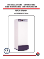
INSTALLATION, OPERATING
AND SERVICING INSTRUCTIONS
DELTA Classic
Combination boiler
with atmospheric burner
05/11/2002
ACV reserves the right to modality the technical specifications and components of its products without prior notice.
664Y0100
INDEX
1
1
INTRODUCTION
2
1.1
1.2
1.3
1.4
Intended users of these instructions
Symbols
Applicable standards
Warnings
2
2
2
2
2
INSTALLATION
3
2.1
2.2
2.4
Boiler room
Connections
Electrical connection
3
3
5
3
START-UP
6
3.1
3.2
Filling the heating and hot water circuits
Atmospheric burner troubleshooting
6
6
4
SERVICING
6
4.1
4.2
4.3
4.4
4.5
4.6
Recommendation
Servicing the gas boiler
Servicing the safety devices
Servicing the burner
Emptying the boiler
Spare parts
6
6
6
7
7
7
5
DESCRIPTION
8
5.1
5.2
5.3
Overview
Description of operation
Design features
8
8
9
6
TECHNICAL SPECIFICATION
10
6.1
6.2
6.3
6.4
6.5
Effective dimensions
Maximum operating conditions
Domestic hot water performance
Boiler performances
Atmospheric burner
10
10
10
10
11
7
USER GUIDE
12
7.1
7.2
Using the boiler
Boiler room
12
13
1.1
INTRODUCTION
INTENDED USERS OF THESE INSTRUCTIONS
These instructions are intended for:
- the specifying engineer
- the installation engineer
- the user
- servicing technicians
1.2
SYMBOLS
The following symbols are used in these instructions:
Essential instruction for operating the system
correctly.
Essential instruction for personal safety and
environmental protection.
Danger of electrocution.
Risk of burns.
1.3
APPLICABLE STANDARDS
The products have received the “EC” certificate in accordance with the
standards prevailing in different countries (European Directives
90/42/EEC, “efficiency”, 90/396/EEC “gas appliances”). These products
have also received the Belgian “HR+” mark.
1.4
WARNINGS
These instructions are an integral part of the equipment to which they
refer and must be supplied to the user.
The product must be installed and serviced by qualified engineers, in
compliance with the prevailing standards.
ACV accepts no liability for any damage resulting from incorrect
installation or from the use of components or fittings not specified by
ACV.
Failure to observe instructions regarding tests and test
procedures can result in personal injury or pollution
risks.
2
Note:
ACV reserves the right to modify the technical specifications and
components of its products without prior notice.
2
2.1
INSTALLATION
2.2.2
BOILER ROOM
2.2.2.1
Examples of basic circuit configurations
The drain valve and safety valve must be connected to the sewer
drain.
2.1.1 ACCESS
The boiler room must be large enough to allow good access to the
boiler. The following minimum distances (mm) are required around the
boiler:
- front
- rear
500
150
- sides
- above
CENTRAL HEATING CONNECTION
100
700
9
2.1.2
VENTILATION
The boiler room must be fitted with top and bottom vents according to
the table below.
7
4
2
2.1.3
BASE
The base on which the boiler rests must be made of non-combustible
materials.
9
3
2.2 CONNECTION
6
5
2.2.1
CHIMNEY CONNECTION
The boiler can be connected to a standard flue that complies with the
regulations in force or is connected to a chimney. It must be easy to
remove to give access to the flue pipes when servicing the boiler.
10
Top vent
Bottom vent
Chimney height
Chimney diameter
Fig. 2: Configuration with circulator controlled
by a room thermostat
D
C
A.
B.
C.
D.
A
1.
2.
3.
4.
5.
6.
7.
8.
9.
10.
3-way manual motorisable mixer valve
Safety valve pre-set to 3 bar with pressure gauge
Circulator
Non-return valve
System filling valve
Expansion tank
Room thermostat
ACV 13 controller (see controller kit page 5)
Central heating isolating valve
Drain valve
B
9
9
Fig. 1: Boiler room ventilation and chimney connection
2
G20
G25
G30-P30
m3/h
dm2
dm2
96,6
1,5
1,6
119,3
1,5
2
140,4
1,5
2,3
mm
mm
mm
153
153
153
157
153
153
170
153
153
3
1
Ventilation
Min. fresh air requirement
Top vent (A)
Bottom vent (B)
8
4
6
5
Chimney
C = 5 m Ø min. F
C = 10 m Ø min. F
C = 15 m Ø min. F
IMPORTANT
Boilers must be installed by a qualified engineer, in
accordance with the prevailing local standards and
regulations.
10
Fig. 3: Configuration with motor driven mixer valve
3
2
INSTALLATION
2.2.2.2
ACV circulation kit
ACV offers an optional pre-assembled circulation kit comprising:
- a circulator.
- a 3-way manual motorisable valve.
- connecting pipes including a second optional circuit.
- two isolating valves.
- adapters for mounting safety valve and filling valve to right or
left of expansion tank.
2.2.2.3
Discharge
The drain cock and safety valve must be connected to the waste
water system in accordance with current regulations.
2.2.3
DOMESTIC HOT WATER CONNECTION
Fig. 4: ACV circulation kit assembly
2.2.3.1
Pressure reducer
If the water mains pressure is greater than 6 bar, a pressure
reducer calibrated to 4.5
bar must be fitted.
2.2.3.2
Safety unit
The tank safety unit must be ACV approved and calibrated to 7
bar.
The valve discharge must be connected to the sewer drain.
2.2.3.3
Hot water expansion tank
Installing a hot water expansion tank avoids any risk of pressure
surges due to water-hammer.
5
2
7
4
8
1
9
6
2.2.3.4
Hot water circulation
If the tank is situated a long way from the point of use, then
installing a closed return circuit can provide a faster supply of
hot water always available.
2.2.3.5
1.
2.
3.
4.
5.
6.
7.
8.
9.
Description
Safety unit
Pressure reducer
Thermostatic mixing valve
Hot water circulator
Non-return valve
Hot water expansion tank
Inlet valve
Draw-off valve
Emptying valve
Fig. 5a: Configuration without thermostatic mixing valve
5
IMPORTANT
As a safety measure against burns, we strongly advise
installing a thermostatic mixing valve (recommended
temperature: 60° C).
2
7
4
8
1
3
9
6
Optional fittings available
Safety unit
Pressure reducer
Thermostatic mixer
Hot water expansion tank
Ø 3/4”
Ø 3/4”
Ø 3/4”
5 litres
Fig. 5b: Configuration with thermostatic mixing valve
4
2
2.2.4
INSTALLATION
CONTROLLER KITS
KIT 1: ACV 13.00 / Basic
Basic kit for regulating flow temperature according to
weather conditions.
It comprises: temperature regulator with analogue timer,
water temperature detector (-30/130° C), outside temperature
detector (-30/50° C), 230V - 3 spindle servomotor SQY 31
and intermediate socket.
Fig. 6a: kit 1
KIT 1: ACV 13.00 / Standard
Basic kit for regulating flow temperature according to
weather conditions.
It comprises: temperature regulator with analogue timer,
water temperature detector (-30/130° C), outside temperature
detector (-30°/50' C), 230V - 3 spindle servomotor SQY
349 and intermediate socket.
Fig. 6b: kit 2
Wiring diagram of ACV controller kits (fig. 7)
SQK 349
B2.
B9.
B5.
P1.
Y1/Y2/N.
B9
B3
B2
QAAD50
(QAAD70) QAC32
QAD22
N
Mixer valve (SQK349)
19
18
17
16
15
14
13
12
11
10
9
8
7
6
5
4
3
2
L1
ALIMENTATION
1
230V / 50 Hz
Blue N
Black Y2
Brown Y1
20
19
18
17
16
15
14
13
12
11
N Y2 Y1
2.3
B5
bl n/z br
20
bl.
n/z.
br.
230V
P1
Water temperature detector
Outside temperature detector
Analogue/digital room thermostat
Central heating pump
10
9
P1
8
7
B5
6
5
B9
4
3
B3
2
1
B2
ELECTRICAL CONNECTION
12
2.3.1
POWER SUPPLY
The boiler operates with a 230 V - 50 Hz single phase supply. An
on-off switch box with 6 A fuses must be fitted outside the boiler to
allow power to be shut off during servicing and before any repairs are
carried out on the boiler.
L1
N
M
1
1
2
C
T
M
O
6
2.3.2
COMPLIANCE
Boiler installation must comply with the prevailing local standards and
legislation.
2.3.3
SAFETY
The stainless steel tank must be earthed separately.
2.3.4
BURNER ELECTRICAL CONNECTION
The burner is supplied with power by a 3-core cable.
1
3
2 4
5
Fig. 8: Control panel
3
M
B
7
O
N
M.
O.
N.
B.
R.
T.
Brown
Orange
Black
Blue
Red
Green-yellow
1.
2.
3.
4.
5.
6.
7.
8.
9.
10.
11.
12.
Boiler thermostat (60/90° C)
On/off switch
Summer/winter selector
Thermometer
Controller (optional)
TTB
Cut-off thermostat (95° C max.)
Safety thermostat (103° C max.)
Plug (power and control)
Room thermostat
Heating pump connection
To gas valve
8
N
B
2
B
R
L1
N T1 T2 S3
L1
N T1 T2 S3
230V-50 Hz
6A
9
The power to the boiler must be switched off before any
work is carried out.
B
11
1O
Fig. 9: Boiler wiring
5
3
3.1
START-UP
4
FILLING THE HEATING AND HOT
WATER CIRCUITS
1. Fill the domestic hot water circuit and bring it up to pressure.
4.1
RECOMMENDATION
ACV advises that boilers should be serviced at least once a year.
The burner must be serviced and tested by a competent engineer.
4.2
IMPORTANT
The hot water tank must be pressurised before the
heating circuit is filled.
2. Fill the heating circuit taking care not to exceed the 2 bar pressure
limit.
3. Vent the air from the top of the boiler.
4. After venting the air from the system, bring the pressure up to the
static head plus 0.5 bar: 1.5 bar = 10 m – 2 bar = 15 m.
5. Check the power connection, the boiler room ventilation, and ensure that there are no leaks in the flue gas discharge pipes.
6. Set the thermostat (1) to between 60 and 90° C.
1
3
SERVICING
SERVICING THE GAS BOILER
1 - Switch off the power at the mains switch outside the boiler and
close the gas tap.
2 - Set the on/off switch on the control panel to the OFF position.
3 - Release and remove the chimney flue (1) to free the top of the
boiler.
4 - Remove the jacket top (2) and lift off the flue reducer (3).
5 - Remove the baffles (4) from the flue pipes (5) for cleaning. Replace
them if in poor condition.
6 - Unscrew the burner chamber plate (6).
7 - Brush the flue pipes (5).
8 - Clean the burner chamber (7) and the burner (8).
9 - Check that the insulation on the burner chamber plate (6) is in
good condition.
2
1.
2.
3.
4.
5.
6.
7.
8.
Chimney flue
Jacket top
Chimney flue reducer
Baffles
Flue pipes
Burner chamber plate
Burner chamber
Burner
1
2
3
Fig. 10: Control panel
7. Set the Summer/Winter selector (3) to the desired position.
8. Switch the on/off switch (2) to the ON position.
9. Check the gas supply pressure on starting up.
3.2
BURNER TROUBLESHOOTING
Refer to the servicing and troubleshooting instructions for the burner.
5
Before servicing or repairs, switch off the power at the
mains switch fitted in the boiler room by the electrician.
4
6
8
7
Fig. 11: Main components.
4.3
-
-
6
SERVICING THE SAFETY DEVICES
Check that all thermostats and safety devices are working properly:
boiler thermostat, cut-off thermostat and manually reset safety
thermostat.
Test the safety valves on the central heating and hot water circuits
4
4.4
-
SERVICING
SERVICING THE BURNER
Check and clean the burner and ignition electrode.
Check that the safety components are working properly.
4.5
EMPTYING THE BOILER
4.5.1
EMPTYING THE PRIMARY CIRCUIT (central heating):
1
1
1. Switch off the power to the boiler at the mains switch installed by
the electrician.
2. Close the isolating valves (1) of the boiler system.
3. Connect a hose to the drain valve (2).
Ensure that it is attached properly.
4. Open the drain valve and let the hot water drain out.
2
5. When the boiler is empty, return the isolating and safety valves to
their initial positions.
4.5.2
Fig. 12a: Emptying the primary circuit
EMPTYING THE HOT WATER TANK:
1. Switch off the mains power to the boiler at the external switch
installed by the electrician.
2. Relieve the pressure in the primary circuit.
3. Close valves (A) and (B).
4. Open valves (C) and (D) (first C then D).
5. Let the water drain away.
B
A
D
6. After emptying, return the valves to their initial positions.
For the tank to be emptied, valve (C) must be situated at
ground level.
4.6
SPARE PARTS
C
Refer to the specific document available from ACV or your distributor.
Fig. 12b: Emptying the hot water circuit
7
5
5.1
•
•
•
•
•
•
•
•
•
5.2
DESCRIPTION
OVERVIEW
Combination boiler (central heating and domestic hot water).
Designed for venting through a chimney.
TANK-IN-TANK indirect storage type domestic hot water production.
Fittings necessary for connecting the circulation kit for feeding the
heating circuit (available as an option).
Control panel with on/off switch, adjustable thermostat, thermometer,
“Summer/Winter” selector and knockout for fitting ACV integrated
control system (optional).
Flue gas anti-backdraught safety device.
Delivered complete with atmospheric type burner.
DELTA Classic models G20, G25 and G30, for natural gas, with
rated outputs of 23.2, 28.7 and 34 kW.
DELTA Classic model P30, for propane, with a rated output of
34.4 kW.
DESCRIPTION OF OPERATION
5.2.1
THE TANK-IN-TANK CONCEPT
The DELTA Performance series differs from traditional hot water
producers because of its ring-shaped tank immersed in the primary
fluid contained in the outer body. When there is a demand for hot water
from the central heating system or the domestic hot water system, the
thermostat starts the burner. The combustion gases quickly heat up the
primary fluid, creating a natural circulation around the tank.
Fig. 13: Stainless steel domestic hot water tank
5.2.2
DOMESTIC HOT WATER HEATED INDIRECTLY
This circulation facilitates heat exchange between the primary fluid and
the domestic water, which takes place all over the tank surface. The
corrugations on the inner and outer shells of the ring-shaped tank
further boost the area of heat exchange and speed up the heating
process of the domestic water.
4
5.2.3
EASY SETTING AND SAFETY ASSURED
With a single command, the water temperature of both the primary
circuit and the hot water circuit is set by the adjustable thermostat
situated on the tank in the primary circuit. A cut-off thermostat, placed
on top of the boiler, automatically cuts out the burner when the water
temperature in the primary circuit reaches 95° C. A manually reset
safety thermostat shuts off the burner if the temperature reaches
103° C.
2
1
3
5
Fig. 14: Overview of boiler
1.
2.
3.
4.
5.
8
Primary fluid
Domestic hot water
Combustion chamber
Control thermostat
Burner
5
5.3
DESCRIPTION
DESIGN FEATURES
5.3.1
OUTER BODY
The outer body containing the primary fluid is made of STW 22 steel.
5.3.2
TANK-IN-TANK TYPE EXCHANGER ACCUMULATOR
The ring-shaped inner tank with its large heating surface for producing
domestic hot water is built of Chrome/Nickel 18/10 stainless steel. It is
corrugated over its full height by an exclusive production process and
entirely argon arc welded by the TIG (Tungsten Inert Gas) method.
5.3.3
COMBUSTION GAS CIRCUIT
The combustion gas circuit is protected by cold galvanisation. The
combustion gas circuit comprises:
5.3.3.1
Flue pipes
Depending on output, DELTA Classic models contain 4 or 8 steel
flue pipes with an internal diameter of 64 mm. Each pipe is fitted
with a baffle of special steel designed to improve heat exchange
and reduce flue gas temperature.
5.3.3.2
Combustion chamber
The combustion chamber on DELTA Classic models is water
cooled.
1.
2.
3.
4.
5.
6.
7.
8.
9.
10.
11.
12.
13.
14.
15.
16.
17.
18.
19.
20.
Inner ring-shaped domestic hot water tank
External body containing central heating circuit
Insulation
Jacket
Flue pipes
Baffles
Control thermostat 60/90° C
Lower heating return
Combustion chamber
Burner chamber plate
Boiler drain
Upper heating flow and return
Chimney connection
Control panel
Domestic hot water outlet
Domestic cold water inlet
Cut-off thermostat 95° C / Thermometer
Manually reset safety thermostat 103° C
Gas burner
Burner chamber disk.
17
13
4
15
7
14
5.3.4
INSULATION
The boiler body is fully insulated by rigid polyurethane foam with a high
thermal insulation coefficient, sprayed on without the use of CFCs.
12
16
18
5.3.5
JACKET
The boiler is covered by a steel jacket which has been scoured and
phosphated before being stove enamelled at 220° C.
1
2
5.3.6
BURNER
DELTA Classic boilers are fitted with an atmospheric burner with electric ignition.
3
5
6
IMPORTANT
When starting the burner for the first time and when
servicing it, refer to the technical instructions supplied
with it.
5.3.7
1
2
3
4
5
-
20
7
19
8
10
9
CONTROL PANEL (Fig. 15)
Thermostat adjustable between 60 and 90° C
On/off switch
Summer/winter selector
Thermometer
Knockout for (optional) controller.
11
Fig. 15: Boiler structure
1
3
2 4
5
Fig. 16: Control panel
9
6
6.1
TECHNICAL SPECIFICATION
EFFECTIVE DIMENSIONS
C
570
The units are delivered fully assembled, tested and packed on a
timber base with shockproof edges and protected by heat-shrunk
plastic film. On reception and after unpacking, check the equipment for
damage. For transport purposes, refer to the weights and dimensions
given below.
B
MAXIMUM OPERATING CONDITIONS
A
160
6.2
200
Maximum service pressure (tank full of water)
- Primary circuit: 3 bar
- Secondary circuit: 10 bar
118 158
D
Test pressure (tank full of water)
- Primary circuit: 4.5 bar
- Secondary circuit: 13 bar
542
E
Operating temperature
- Maximum temperature: 90° C
6.3
Fig. 17: Effective dimensions
Dimensions
G20
G25
G30/P30
A
1697
1697
1697
B
1460
1460
1460
C
154
154
154
D
360
390
390
Kg
712
712
712
DOMESTIC HOT WATER PERFORMANCE
Domestic hot water performances
G20
G25
G30
P30
Operating at 80° c
Peak delivery at 40° C
(6T = 30° C)
litres/10’
266
339
339
339
Peak delivery at 40° C
(6T = 30° C)
litres/60’
820
1025
1151
1161
Continuous delivery 40° C
(6T = 30° C)
litres/h
665
823
975
986
Operating at 80° c
Initial heating time
minutes
40
29
24
24
After draw-off of 140 l à 45° C
minutes
16
12
10
10
litres/minutes
11
14
14,5
14,5
P30
Specific delivery
Results obtained without a thermostatic mixing valve and with water supply at 10° C
6.4
BOILER PERFORMANCES
G20
G25
G30
Input
kW
26,1
33,1
39,0
40,0
Output
kW
23,2
28,7
34
34,4
Combustion efficiency
%
89
89
89
89,5
Maintenance loss at 60° C as % of rated value
%
1,3
1
0,8
0,87
g/sec.
20
25
30
30
%
9
9
9
10
Mass rate of combustion products
Average CO2
Total capacity
litres
178,5
167,5
167,5
167,5
Primary circuit capacity
litres
114,5
87,5
87,5
87,5
Heating connection
Ø
1”
1”
1”
1”
Hot water connection
Ø
3/4”
3/4”
3/4”
3/4”
Hot water tank heat exchange surface
m2
1,59
2,46
2,46
2,46
Weight empty
Kg
154
186
186
186
B11 BS
B11 BS
B11 BS
B11 BS
Chimney connection
10
6
6.5
TECHNICAL SPECIFICATION
ATMOSPHERIC BURNER
G20
G25
G30
P30
BE - FR
mbar
m3/h
13,3
2,76
12,8
3,50
12,3
4,13
-
AT - DK
ES - GB
IT - PT
IE - SE
mbar
m3/h
13,4
3,10
13,4
3,88
13,4
4,50
-
BE - FR
ES - GB
IE - PT
I 3P
mbar
m3/h
-
-
-
28,5
1,64
NL
I 2L
450
470
510
3x190
LU - DE
I 2ELL
I E2+
Gas G20 - 20 mbar - I E2+ - I 2E LL
Burner pressure
Flow rate
I 2H
Gas G25 - 25 mbar - I 2L
Burner pressure
Flow rate
Gas G31 - 37/50 mbar - I 3P
Burner pressure
Flow rate
1/100 mm
Injectorr Ø
6.5.1
-
START-UP
1. Flame holders
2. Ionisation ignition electrode
3. Reset button
Flush the gas pipe thoroughly, activate the room thermostat and
set the control thermostat for heat demand.
Open the gas tap.
Turn on the main switch on the control panel.
IMPORTANT:
1
2
8
-
The burner is preset at the factory.
-
Check the gas supply pressure and the pressure at the burner
when starting up.
3
7
LEGEND:
1.
2.
3.
4.
Gas electro-valves
Upstream gas pressure test point
Pressure regulator
Burner gas pressure test point
6
5
4
Fig. 19: Natural gas atmospheric burner
1
1
2
8
7
6
3
4
5
3
Fig. 18: Burner valve
2
4
1.
2.
3.
4.
Ionisation ignition electrode
Flame holders
Injector
Reset button
Fig. 20: Propane atmospheric burner
11
7
USER GUIDE
7.1
USING THE BOILER
7.1.2
7.1.1
GETTING TO KNOW THE CONTROL PANEL (Fig. 21)
Your system is fitted with a heating safety valve set to 3 bar, with a
pressure gauge.
Before doing any work on the boiler, switch off the power
at the mains switch installed in the boiler room by the
electrician.
On the control panel, switch off the ON/OFF switch.
Ensure that the water in the system is always pressurised. When cold,
and the air in the system has been vented, the pressure gauge must
show a pressure between 0.5 and 1.5 bar, depending on the height of
the building (1 bar = 5m / 1.5 bar = 10 m and 2 bar = 15 m).
To add water, open the filling valve (Fig. 2 and 3 page 3). Close the valve
after filling. Vent the air in the system to get an accurate water
pressure reading.
(item 2, Fig. 21)
1 - Control thermostat 60 to 90° C (item 1, Fig. 21)
Central heating systems are generally designed to operate at 80° C
maximum. If they are operated at a lower temperature, a 3-way mixer
valve installed on the heating flow pipe (see Fig. 3, page 3) allows the
temperature to be set manually or, if you decide to install a regulator
(§ 2.2.4), automatically.
We recommend you set the thermostat to the maximum values to get
the best from the domestic hot water system.
7.1.3
HEATING SYSTEM GAUGE PRESSURE
SAFETY VALVE (central heating)
(item 2, Fig. 3, page 3)
The drain pipe to waste water system drain must
be iaw current regulations.
In the event of a fault after this short trial, inform the
installing engineer.
The water stored in the domestic hot water tank in the boiler can be at
a very high temperature.
In all cases, install the thermostatic mixer (Fig. 5b, page 4) on the domestic hot water flow pipe which must not exceed 60° C.
A blender or mixing valve is recommended at each point of use.
2 - ON/OFF switch (item 2, Fig. 21)
This must be used to switch off the boiler before working on it.
3 - Summer/winter selector (item 3, Fig. 21)
“Winter” position: activates both the hot water and central heating functions. “Summer” position: the room thermostat or regulator (§ 2.2.4) is
switched off. The heating circulator is also switched off. Only the
domestic hot water function is provided. You can lower the temperature
on the thermostat (1) to save energy. If there is not enough hot water,
we recommend setting the thermostat (1) to its maximum value.
When the next heating season begins, simply select “Winter” to
reactivate the heating system.
4 - Thermometer (item 4, Fig. 21)
Reads the temperature of the boiler primary circuit (central heating)
directly.
5 - Regulator (item 5, Fig. 21)
See the user instructions enclosed if you have chosen this option.
1
3
2 4
Fig. 21: Control panel
12
5
7.1.4
SAFETY UNIT (domestic hot water)
(item 1, Fig. 5a and 5b, page 4)
A monthly inspection is recommended.
Lift the lever on the emptying device for a few seconds to ensure that
the safety valve is working properly.
The drain pipe to waste water system drain must
be iaw current regulations.
In the event of a fault after this short trial, inform the
installing engineer.
7
7.1.5
USER GUIDE
GAS BURNER - RESETTING
If the atmospheric burner is not working:
1. Remove the protective cover.
2. Press the red button to start the burner.
7.2
BOILER ROOM
• Keep vents free at all times.
• Do not store inflammable products in the boiler room.
• Take care not to store corrosive products near the boiler, such
as paints, solvents, chlorine, salt, soap and other cleaning
products.
• If you smell gas, do not switch on the light or light a flame. Turn
off the mains gas tap at the meter and inform the appropriate
services immediately.
Fig. 22: Burner reset button
3. If the burner lights, replace the cover.
If the burner is not working, isolate the electricity
supply before attempting to reset the safety thermostat.
4. Remove the front panel of the casing and reset the safety
thermostat positioned on top of the boiler.
Wait until the boiler temperature is below 60 °C. Then
replace the casing front panel.
Fig. 23: Safety thermostat reset button
5. If the burner lights, replace the cover.
6. If the fault persists, notify the installing engineer.
Starting the burner.
In normal operation, the gas burner starts automatically whenever the
boiler temperature falls below the set temperature.
To ensure your system operates properly, have it
professionally serviced once a year before the central
heating season begins.
13
INTERNATIONAL
ACV international n.v
KERKPLEIN, 39
B-1601 RUISBROEK - belgium
TEL.: +32 2 334 82 20
FAX: +32 2 378 16 49
E-MAIL: [email protected]
AUSTRALIA
ESPAÑA
PORTUGAL
ACV PACIFIC PTY.LTD
UNIT 7, 10 ANELLA AVENUE
CASTLE HILL NSW 2154 - AUSTRALIA
TEL.: +61 2 88 50 45 88
FAX: +61 2 88 50 45 99
E-MAIL: [email protected]
ACV ESPAÑA
C/ANTONIO GAUDI, 3
E-08349 CABRERA DE MAR - ESPANA
TEL.:+34 937 595 451
FAX:+34 937 593 498
E-MAIL: [email protected]
BELGIUM
FRANCE
BOILERNOX LDA
RUA OUTEIRO DO POMAR
CASAL DO CEGO, FRACÇÃO C,
PAVILHÃO 3 - MARRAZES
2400-402 LEIRIA - PORTUGAL
TEL.:+351 244 837 239/40
FAX:+351 244 823 758
E-MAIL: [email protected]
ACV BELGIUM nv/sa
KERKPLEIN, 39
B-1601 RUISBROEK-BELGIUM
TEL.: +32 2 334 82 40
FAX: +32 2 334 82 59
E-MAIL: [email protected]
ACV FRANCE sa
31, RUE AMPERE - Z.I MI - PLAINE
F-69680 CHASSIEU - FRANCE
TEL.:+33 4 72 47 07 76
FAX:+33 4 72 47 08 72
E-MAIL: [email protected]
CHILE
ITALIA
ALBIN TROTTER Y ACV LTDA
SAN PABLO 3800
QUINTA NORMAL - SANTIAGO - CHILE
TEL.:+56 2 772 01 69
FAX:+56 2 772 92 62/63
E-MAIL: [email protected]
ACV ITALIA
VIA MALPIGHI 6
I-48018 FAENZA (RA) - ITALIA
TEL.:+39 0546 62 25 15
FAX:+39 0546 62 25 05
E-MAIL: [email protected]
CZECH REPUBLIC
NEDERLAND
ACV CR SPOL. s.r.o
NA KRECKU 365
CR-109 04 PRAHA 10 - CZECH REPUBLIC
TEL.:+420 2 720 83 341
FAX:+420 2 720 83 343
E-MAIL: [email protected]
ACV NEDERLAND bv
POSTBUS 350
NL-2980 AJ RIDDERKERK - NEDERLAND
TEL.:+31 180 42 10 55
FAX:+31 180 41 58 02
E-MAIL: [email protected]
DEUTSCHLAND
POLAND
ACV DEUTSCHLAND Gmbh
GEWERBEGEBIET GARTENSTRASSE
D-08132 MÜLSEN ST.JACOB - DEUTSCHLAND
TEL.:+49 37601 311 30
FAX:+49 37601 311 31
E-MAIL: [email protected]
ACV POLSKA sp. z.o.o.
BUIRO GLOWNE
PL-87 - 702 KONECK - POLAND
TEL.:+48 54 272 23 00
FAX:+48 54 272 23 01
E-MAIL: [email protected]
ARGENTINA
GREECE
ROMANIA
TECNOPRACTICA
ALFEREZ BOUCHARD 4857
1605 CARAPACHAY - BUENOS AIRES
TEL.: +54 11 47 65 33 35
FAX: +54 11 47 65 43 07
E-MAIL: [email protected]
ESTIAS
MARASLI STREET 7
54248 THESSALONIKI - GREECE
TEL.:+30 310 31 98 77
FAX:+30 310 31 97 22
E-MAIL: [email protected]
SC TRUST EURO THERM SA
D.N PIATRA NEAMT - ROMAN
km 2 C.P 5 O.P 3 jud. Neamt
5600 PIATRA NEAMT - ROMANIA
TEL.:+40 33 20 62 06
FAX:+40 33 20 62 00
E-MAIL: [email protected]
BRAZIL
ÎLE MAURICE
SIMETAL INDUSTRIA E COMERCIO
DE FERRAMENTAS LTDA
RUA GERSON ANDREIS 535
95112 - 130 CAXIAS DO SUL - BRAZIL
TEL.: +55 54 227 12 44
FAX: +55 54 227 12 26
E-MAIL: [email protected]
SOTRATECH
29, RUE MELDRUM
BEAU BASSIN - ÎLE MAURICE
TEL.:+230 46 76 970
FAX:+230 46 76 971
E-MAIL: [email protected]
RUSSIA
ACV RUSSIA
1/9, MALYI KISELNYI
103031 MOSCOW - RUSSIA
TEL.:+7 095 928 48 02 / +7 095 921 89 79
FAX:+7 095 928 08 77
E-MAIL: [email protected]
SLOVAK REPUBLIC
ACV SLOVAKIA s.r.o.
PLUHOVÁ 49
831 04 BRATISLAVA - SLOVAK REPUBLIC
TEL.:+421 2 444 62 276
FAX:+421 2 444 62 275
E-MAIL: [email protected]
UK
ACV UK Ltd
ST. DAVID’S BUSINESS PARK
DALGETY BAY - FIFE - KY11 9PF - SCOTLAND
TEL.:+44 1383 82 01 00
FAX:+44 1383 82 01 80
E-MAIL: [email protected]
USA
TRIANGLE TUBE PHASE III
FREEWAY CENTER - 1 TRIANGLE LANE
BLACKWOOD NJ 08012 - USA
TEL.:+1 856 228 8881
FAX:+1 856 228 3584
E-MAIL: [email protected]
SLOVENIA
Z*MAJ d.o.o.
CESTA OF 49
1420 TRBOVLJE - SLOVENIA
TEL.:+386 356 32 830
FAX:+386 356 32 831
E-MAIL: [email protected]
LITHUANIA
BULGARIA
PROXIMUS ENGINEERING LTD
7 BIAL KREM STR.
9010 VARNA - BULGARIA
TEL.:+359 52 500 070
FAX:+359 52 301 131
E-MAIL: [email protected]
CHINA
BEIJING HUADIAN HT POWER TECHNOLOGY
DEVELOPMENT CO. LTD
ROOM B-912, TOWER B, COFCO PLAZA
N°. 8, JIANGUOMENNEI AVENUE
BEIJING 100005 - PEOPLE’S REPUBLIC OF CHINA
TEL.:+86 10 652 30 363/393 EXT 101
FAX:+86 10 652 27 071
E-MAIL: [email protected]
DENMARK
VARMEHUSET
FRICHSVEJ 40 A
8600 SILKEBORG - DENMARK
TEL.:+45 86 82 63 55
FAX:+45 86 82 65 03
E-MAIL: [email protected]
ESTONIA
TERMOX AS
TAHE 112A
51013 TARTU - ESTONIA
TEL.:+372 736 73 39
FAX:+372 736 73 44
E-MAIL: [email protected]
UAB “GILIUS IR KO”
SAVARNORIU PR. 192
3000 KAUNAS - LITHUANIA
TEL.:+370 7 308 930
FAX:+370 7 731 796
MAROC
CASATHERM
PLACE EL YASSIR
20300 CASABLANCA - MAROC
TEL.:+212 22 40 15 23
FAX:+212 22 24 04 86
MOLDAVIA
STIMEX - PRIM S.R.L.
STR BUCURESTI, 60A
2012 CHISINAU - MOLDAVIA
TEL.:+37 32 22 46 75
FAX:+37 32 27 24 56
E-MAIL: [email protected]
ÖSTERREICH
PROTHERM HEIZUNGSTECHNIK Gmbh
TRAUNUFERSTRASSE 113
4052 ANSFELDEN - ÖSTERREICH
TEL.:+43 7229 804 82
FAX:+43 7229 804 92
E-MAIL: [email protected]
SWEDEN
WÄRMEPRODUKTER I KLIPPAN AB
TEMPLAREGATAN 7
26435 KLIPPAN - SWEDEN
TEL.:+46 435 184 10
FAX:+46 435 184 02
E-MAIL: [email protected]
TUNISIE
SO.CO.ME CHAUMAX
BOÎTE POSTALE N°44
1002 TUNIS - TUNISIE
TEL.:+216 71 78 15 91
FAX:+216 71 78 87 31
UKRAINE
UKRTEPLOSERVICE LTD
PR. LAGUTENKO 14
83086 DONETSK - UKRAINE
TEL.:+38 062 382 60 47/48
FAX:+38 062 335 16 89
E-MAIL: [email protected]