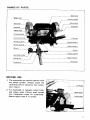
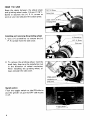
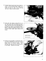
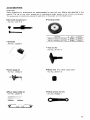
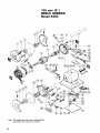
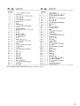
1
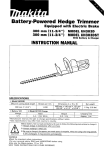
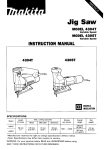
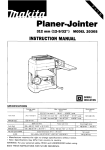
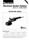
Bench Grinder
125 mm (5") MODEL 9300
INSTRUCTION MANUAL
SPECIFICATI0 NS
Wheel size
1
Hz
1
No load speed
1
Overall length
* Manufacturer reserves the right t o change specifications without notice.
Note: Specifications may differ from country t o country.
I
Net weight
For Your Own Safety Read Instruction
Manual Before Operating
BENCH GRINDER
I
GENERAL SAFETY PRECAUTIONS
(For All Tools)
1. KNOW YOUR POWER TOOL. Read the owner's manual carefully. Learn the
tools applications and limitations, as well as the specific potential hazards
peculiar t o it.
2. KEEP GUARDS IN PLACE and in working order.
3. REMOVE ADJUSTING KEYS AND WRENCHES. Form habit of checking to
see that keys and adjusting wrenches are removed from tool before turning
it on.
4. KEEP WORK AREA CLEAN. Cluttered areas and benches invite accidents.
5. DON'T USE IN DANGEROUS ENVIRONMENT. Don't use power tools in damp
or wet locations, or expose them t o rain. Keep work area well lighted.
6. KEEP CHILDREN AWAY. All visitors should be kept safe distance from work
area.
7. MAKE WORKSHOP KID PROOF with padlocks, master switches, or by
removing starter keys.
8. DON'T FORCE TOOL. It will do the job better and safer at the rate for which
it was designed.
9. USE RIGHT TOOL. Don't force tool or attachment t o do a job for which it
was not designed.
10. WEAR PROPER APPAREL. Wear no loose clothing, gloves, neckties, rings,
bracelets, or other jewelry which may get caught in moving parts. Nonslip
footwear is recommended. Wear protective hair covering t o contain long hair.
11. ALWAYS USE SAFETY GLASSES. Also use face or dust mask if cutting
operation is dusty. Everyday eyeglasses only have impact resistant lenses,
they are NOT safety glasses.
12. SECURE WORK. Use clamps or a vise to hold work when practical. It's safer
than using your hand and it frees both hands t o operate tool.
13. DON'T OVERREACH. Keep proper footing and balance at all times.
14. MAINTAIN TOOLS WITH CARE. Keep tools sharp and clean for best and
safest performance. Follow instructions for lubricating and changing accessories.
15. DISCONNECT TOOLS before servicing; when changing accessories such as
blades, bits, cutters, and the like.
16. REDUCE THE RISK OF UNINTENTIONAL STARTING. Make sure switch is
in off position before plugging in.
2
17. USE RECOMMENDED ACCESSORIES. Consult the owner's manual for
recommended accessories. The use of improper accessories may cause risk
of injury t o persons.
18. NEVER STAND ON TOOL. Serious injury could occur if the tool is tipped or
if the cutting tool is accidentally contacted.
19. CHECK DAMAGED PARTS. Before further use of the tool, a guard or other
part that is damaged should be carefully checked t o determine that it will
operate properly and perform its intended function - check for alignment
of moving parts, binding of moving parts, breakage of parts, mounting, and
any other conditions that may affect its operation. A guard or other part
that is damaged should be properly repaired or replaced.
20. DIRECTION OF FEED. Feed work into a blade or cutter against the direction
of rotation of the blade or cutter only.
21. NEVER LEAVE TOOL RUNNING UNATTENDED. TURN POWER OFF. Don't
leave tool until it comes t o a complete stop.
22. PROPER GROUNDING. This tool should be grounded while in use to protect
the operator from electric shock.
23. EXTENSION CORDS: Use only three-wire extension cords which have threeprong grounding-type plugs and three-pole receptacles which accept the
tool's plug. Replace or repair damaged or worn cord immediately.
VOLTAGE WARNING: Before connecting the tool t o a power source (receptacle,
outlet, etc.) be sure the voltage supplied is the same as that specified on the
nameplate of the tool. A power source with voltage greater than that specified
for the tool can result in SERIOUS INJURY t o the user - as well as damage to
the tool. If in doubt, DO NOT PLUG IN THE TOOL. Using a power source with
voltage less than the nameplate rating is harmful t o the motor.
3
GROUNDING INSTRUCTIONS
ALL GROUNDED, CORD-CONNECTED TOOLS: In the event of a malfunction or
breakdown, grounding provides a path of least resistance for electric current t o
reduce the risk of electric shock. This tool is equipped with an electric cord having an equipment-grounding conductor and a grounding plug. The plug must be
plugged into a matching outlet that is properly installed and grounded in accordance with all local codes and ordinances.
Do not modify the plug provided - if it will not fit the outlet, have the proper outlet
installed by a qualified electrician.
Improper connection of the equipment-grounding conductor can result in a risk
of electric shock. The conductor with insulation having an outer surface that is
green with or without yellow stripes is the equipment-grounding conductor. If
repair or replacement of the electric cord or plug is necessary, do not connect
the equipment-grounding conductor t o a live terminal.
Check with a qualified electrician or serviceman if the grounding instructions are
not completely understood, or if in doubt as t o whether the tool is properly
grounded.
Grounded, cord-connected tools intended for use on a supply circuit having a
nominal rating less than 150 volts: This tool is intended for use on a circuit that
has an outlet that looks like the one illustrated in Figure A. The tool has a grounding plug that looks like the plug illustrated in Figure A. A Temporary adapter, which
looks like the adapter illustrated in Figure B and C, may be used t o connect this
plug to a 2-pole receptacle as shown in Figure 6 if a properly grounded outlet
is not available. The temporary adapter should be used only until a properly
grounded outlet can be installed by a qualified electrician. The green-colored rigid
ear, lug, etc. extending from the adapter must be connected t o a permanent
ground such as a properly grounded outlet box.
GROUNDING METHODS
FIG. 6
FIG. A
9
1
Grounding Pin
-Cover of GroundedOutlet Box
-
FIG. C
Adapter
9
Grounding
Means
4
ADDITIONAL SAFETY RULES FOR BENCH GRINDER
1. Be sure that the guards are in place t o protect the operator against flying
debris and injury in case the wheel breaks.
2. Check the wheel for cracks and chipped edges before mounting and/or
running it. Stand away from the front of the wheel and run for more than
one minute t o test it. Replace if you note anything abnormal. Then test new
wheel for more than 3 minutes.
3. Use only the face of a straight wheel and the side of a cup wheel when
grinding. Avoid sudden feeds of work into wheel t o minimize the possibility
of cracks or breakage.
4. Do not strike or drop the wheel. Use only the shaft, flanges, nuts and other
installing parts specified by Makita. Handle them carefully and remove any
foreign matter adhering to them.
5. Always wear safety goggles when grinding. Also wear a face mask if there
is much dust.
6. Stand aside and let wheel come up to full speed after switching on, before
you start to use the grinder.
7. Stop work and switch off immediately whenever the wheel stops or emits
a strange noise during operation.
8. Metal grinding creates sparks. Keep the area around the grinder free of
anything ignitable: oil, gas, glue, bond, paint, etc.
9. Replace cracked, chipped or damaged wheels immediately. Install carefully
in accordance with the instruction manual.
IO. Use only wheels of specified dimensions indicated on the bench grinder label.
The inside and outside of the grinding wheel (flange contacting portions)
should have a label, or the wheel should not be used. Use only a grinding
wheel with a maximum safe speed over the maximum wheel speed stated
on the bench grinder. Use only a wheel with the hole size that fits the tool
shaft. *Arbor size 12.7m m (1/2”).
Do not attempt to enlarge the hole size or use bushings to compensate for
a loose fit. Never use the grinder with a loose grinding wheel.
1 1 . Be sure the wheel you intend to mount as a replacement has no cracks,
chipped areas or defects. Mount wheel on a rod or pencil through arbor hole
and tap side lightly with a wooden handle or piece of wood. If it rings clear
when tapped at several places when the wheel is rotated, the wheel can
be used.
12. If nut is loose, running the wheel can be extremely dangerous. On the other
hand, a wheel that is tightened too much can be damaged and thus be a
danger. Use the standard equipped wrenches and secure in accordance with
the instruction manual procedure.
13. Do not let your fingers or clothing become caught in a revolving wheel. Also,
do not leave a bench grinder running unattended.
5
14. Adjust tool rests so they are within 1 m m (1132") - 3 m m (118") of the
grinding wheel. Height of tool rests should be so that are level with the middle
(center) of the wheels.
15. Always keep the clearance between the face of a straight wheel and the
adjust plate less than 1.6 m m (1116"). With a cup wheel, the adjust cover
should be within 1 m m (1132") - 3 m m (118") from the wheel surface. This
will prevent bodily harm should the wheel fly apart and or something become
caught inside.
16. For safe use, keep the standard-equipped eyeshields in position at all times.
17. Before switching on the grinder, turn the grinding wheel by hand t o make
sure it is not contacting the work or tool rest.
18. Be very careful how you attach or remove work from the tool rests and also
where you set the work.
19. Unplug the tool and hold by means of the base when carrying.
20. Replace cracked wheel immediately.
21. Always use guards and eye shields.
22. Do not overtighten wheel nut.
23. Use only flanges furnished with the grinder.
24. Adjust distance between wheel and work rest to maintain 118 inch or less
separation as the diameter of the wheel decreases with use.
25. Frequently clean grinding dust from beneath grinder.
SAVE THESE INSTRUCTIONS.
6
NAMES OF PARTS
Shaft lock
Grinding wheel
I
Thumb screw C
BEFORE USE
1. The eyeshields are packed together with
the bench grinder. Always install the
eyeshields before operation (see explanatory figure).
2. Fit eyeshields in between wheel cover
and adjust plate (fitting small screws
into installation holes on eyeshields).
Secure tightly with P. H. screws.
'\\
Eyeshleld
-
_ plate
_
.-Aajust
7
HOW TO USE
Keep the space between the adjust plate
and grinding wheel under 1.6 mm (1/16").
Screw in securely the (+) P. H. screws as
soon as you have adjusted the adjust plate.
(+) P. H. Screw
Under 1 6 m
Installing and removing the grinding wheel
1. Use a (+) screwdriver to remove the
P. H. screws from the side cover.
(+I
I
8
Toggle switch
\
I
Sharpening planer blade
1. How to fit planer blade holder set
In the case of fitting the planer blade to
the slider, two thumb screws of planer
blade holder should be tightened so that
the slider should always be contacted
closely with the blade gauge A side, and
the edge of blade should be contacted
with i t s gauge 6 side.
Thumb screw M5 x 10
r
I4
1
I]
1
q
Blade
Ease gauge
/
\
aauae A side
Blade gauge E side
Slider
2. Mount the planer blade holder on the
tool rest and sharpen the blade gradually but rather quickly, moving it back
and forth across the face of the wheel.
-
c a n e r ~olade holder
Tool rest
3. To adjust the fine adjustment slide, use the adjust screw. Keep the tool rest a t the
same angle as the grinding wheel during operation.
How to use the groove cutter gauge
assembly
Fit the groove cutter onto the gauge shaft
with one cutter edge flush with the side of
the guide (A), fastening it by the thumb
screw. Then, with the guide held in place,
turn the cutter until the other edge comes
flush with the side of the guide (A). Make
sure that both are equidistant from the
middle of the cutter.
Groove
cutter
Thumb screw
Gauge shaft
Washer
9
Assembling circular saw sharpening kit
1. First install fixed rod with cross point
into hole in the inclining tool rest.
Secure with thumb screw B so that
screw end fits into indentation on the
rod.
2. Now slide rod for mounting saw blade
holder and set nut into hole below on
cross point. Secure with thumb screw.
Note flat side of rod should be on the
bottom.
Set blade holder for circular saw into
hole for it on sliding rod. Then set nut
screws into the blade holder hole.
Actual sharpening procedure
1. Unscrew set nut and set circular saw
blade on holder. Secure carefully to
holder with the set nut.
10
2. Loosen thumb screws and move blade in
closer to the grinding wheel. Make sure
blade lies flat on top of the inclining
tool rest. Secure thumb screws.
3. Using the two adjust screws (6,C) on
the right side, work the sliding rod sideways until the tip of the saw blade just
contacts the side of the grinding wheel.
Secure blade with adjust screws so that
uniform stock (teeth tips) removal will
result.
3. Rotate the saw blade in clockwise direction after switching on the tool, cutting
blade teeth to uniform height. This
jointing step evens up the circumference
of the blade. Switch off grinder.
11
5. Keep a clearance of approximately 2mm
(3/32") between the wheel and the
blade teeth for turning. Secure thumb
screw.
Next, draw blade up to wheel so that
the wheel is well into the tooth gullet.
Use adjust screws (B, C) for fixed setting that will assure uniform gullet
depth when sharpening.
I
Y
6. To obtain the original bevel angle or an
angle of 15 degrees, release the thumb
screw below on the inclining tool rest.
Tilt rest to desired angle and secure with
thumb screw.
Now proceed to sharpen blade by grinding every other tooth.
After sharpening on side, readjust inclining tool rest for the same angle for the
opposite-side teeth. Turn blade over
after releasing set nut; set blade on
blade holder and secure with set nut.
Sharpen the other side of the blade (i.e., every other as yet unsharpened tooth) using
the same procedure indicated above.
12
ACCESSORIES
CAUTION :
These accessories or attachments are recommended for use with your Makita tool specified in this
manual. The use of any other accessories or attachments might present a risk of injury to persons.
The accessories or attachments should be used only in the proper and intended manner.
Grinding wheels
Saw blade sharpening kit
Part No. 122174-8
Sire (mml
125 15.J x 1 3 11/29x 12.7 11/2”l
0
I
Grit
WAGOK
I
Part No
741004-0
Eyeshield
Part No. 122203-7
/
0
Tool rest (C)
Part No. 31 1071-5
Cutter gauge set
Part No. 123002-0
Sleeve (13) (For a 5/8” arbor hole)
Part No. 25751 7-6
Planer blade holder set
Part No. 123019-3
Offset wrench (13-21)
Part No. 782004-1
13
125 mm (5")
BENCH GRINDER
Model 9300
Note: The switch and other part configurations
may differ from country to cointry.
14
'LkM
$tD
E
' M $ED
DESCRIPTION
MAC E!
MnC
1
1
P. H. Screw M4.8
2
1
Side Cover I R I
3
1
H. Nut W l 1 2 - 2 1
4
1
Outer Flange 50
IWifh Washer)
IRight-handscrew)
5
1
Inner Flange 50
6
3
P. H. Screw M5r10 IWith Warherl
7
1
Wheel Cover I R I
8
1
stator
9
1
Adlust Plats ( A I
10
2
1
1
P. H. Screw M6x16 (With Washer1
12
13
P," 4.5
DESCRIPTION
UE
40
1
CORD ASSEMBLY
I A s r m b l e d Cord. Plug & Cord Gusrdl
41
1
42
1
P. H Screw M4x0 I W n h Washer)
Side Cover ILI
43
1
H. Nut W112-21
44
1
Outer Flange 50
(Left-hand Screw)
45
1
Inner Flange 50
46
3
P. H. Screw M5x10 (With Washer)
47
1
Wheel Cowr ( L l
48
1
Collar
49
1
Ball Bearing 6202LLB
ROTOR ASSEMBLY
IAsambled Items 13, 14. 16, 17 & 491
50
1
1-1 S. Screw M5x6
51
1
Switch
14
1
PI" 4 5
52
1
H
15
1
Pin 4.5
53
1
F. Washer 0
16
1
Spindle Lock Bush
54
1
T. Screw M5x15
17
1
Ball Bearing 6202LLB
55
2
P. H. Screw M6x16 (With Washer)
10
1
Compression Spring 7
56
1
A d p r t Plate I A l
19
1
Pin 6
Bolt M 8 x m (With Warherl
57
1
Inclined Tool Rest
M
1
Retaining Ring R-12
58
1
Tool Holder
P. H. Screw M6x25 lWith Warherl
59
1
T. Screw M6xZO
21
3
22
1
H. 0011 M6x12
60
1
Spring Pin 6-24
23
1
Bracket
61
2
P ti. Screw M4x0 (With Washed
24
2
P. H. Screw M5x30 lWi1h Washed
62
1
Under Cowr
25
1
T. Screw M6x12
63
P. H Screw M4x8 [With Washed
26
1
Stop Plate
64
2
1
27
2
P.
65
1
Capacitor Clamp
20
1
Rod
66
1
Separator
29
1
Screw M10
67
1
Switch Cover
30
4
Rivet 0-5
60
1
Rubber Cap
31
1
Name Plate
69
1
H. Nu1 M12
32
1
Sllde Plate
70
1
Wave Washer 26
33
1
Makita b b e l
71
1
P. H.Screw M4x8 (Wifh Washed
24
1
MOW
tiOUslng
72
1
EYE SHIELD ASSEMBLY
35
1
Mocor Housing Cover
73
2
P. H. Screw M4x8
37
2
P.
74
1
H.Nut M12
38
1
Strain Relief
1
EYE SHIELD ASSEMBLY
39
1
Cord Guard
H.Screw
H.Screw
M 4 r 8 IWith Washer)
M4x18 (Wnh Warherl
75
70
-
1
-
Capacitor
(With Washed
Toothed Washer 1 2
Note The switch and other part specifications may differ from muntry to Country
15
MAKITA LIMITED ONE YEAR WARRANTY
Warranty Policy
Every Makita tool is thoroughly inspected and tested before leaving the factory. It is warranted to
be free of defects from workmanship and materials for the period of ONE YEAR from the date of
original purchase. Should any trouble develop during this one-year period, return the COMPLETE
tool, freight prepaid, to one of Makita’s Factory or Authorized Service Centers. If inspection shows
the trouble is caused by defective workmanship or material, Makita will repair (or at our option,
replace) without charge.
This Warranty does not apply where:
repairs have been made or attempted by others:
repairs are required because of normal wear and tear:
The tool has been abused, misused or improperly maintained;
alterations have been made to the tool.
IN NO EVENT SHALL MAKITA BE LIABLE FOR ANY INDIRECT, INCIDENTAL OR CONSEQUENTIAL DAMAGES FROM THE SALE OR USE OF THE PRODUCT. THIS DISCLAIMER
APPLIES BOTH DURING AND AFTER THE TERM OF THIS WARRANTY.
MAKITA DISCLAIMS LIABILITY FOR ANY IMPLIED WARRANTIES, INCLUDING IMPLIED
WARRANTIES OF “MERCHANTABILITY” AND “FITNESS FOR A SPECIFIC PURPOSE,”
AFTER THE ONE-YEAR TERM OF THIS WARRANTY.
This Warranty gives you specific legal rights, and you may also have other rights which vary from
state to state. Some states do not allow the exclusion or limitation of incidental or consequential
damages, so the above limitation or exclusion may not apply to you. Some states do not allow
limitation on how long an implied warranty lasts, so the above limitation may not apply to you.
Makita Corporation
3-11-8, Sumiyoshi-cho,
Anjo, Aichi 446 Japan
883078A068
PRINTED IN JAPAN
1991 - 8 - N