1
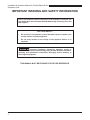
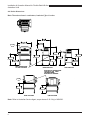
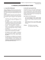
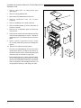
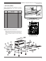
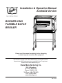
Installation & Operation Manual
Australia Version
BURGER KING
FLEXIBLE BATCH
BROILER
Please read this manual completely before attempting
to install, operate or service this equipment
This manual is Copyright © 2011 Duke Manufacturing Co. All rights reserved.
Reproduction without written permission is prohibited. Duke is a registered
trademark of the Duke Manufacturing Co.
Duke Manufacturing Co.
2305 N. Broadway
St. Louis, MO 63102
Phone: 314-231-1130
Toll Free: 1-800-735-3853
Fax: 314-231-2460
www.dukemfg.com
P/N 175187J
Installation & Operation Manual for Flexible Batch Broiler
Australian Units
2
Installation & Operation Manual for Flexible Batch Broiler
Australian Units
TABLE OF CONTENTS
PAGE
I. General Information.......................................................................................................5
A. Batch Broiler Specifications.......................................................................................5
A-1.0 Model Number Key.......................................................................................5
A-2.0 Broiler Dimensions.......................................................................................6
II. Installation Instructions.................................................................................................7
A. Qualified Personnel...................................................................................................7
B. Delivery and Inspection.............................................................................................7-8
C. Broiler Assembly.......................................................................................................9
D. Adjustments at Installation........................................................................................11
E. Location of the Broiler...............................................................................................12
F. Gas Piping.................................................................................................................12
G. Electrical Connections..............................................................................................12
H Ventilation.................................................................................................................12
III. Operation Instructions..................................................................................................13
A. Broiler Controls..........................................................................................................13
B. Cooking Product........................................................................................................13
B-1.0 Lighting the Broiler.......................................................................................13
B-2.0 Cook Product................................................................................................14
B-3.0 Cook Cycle Complete...................................................................................15
B-4.0 Fine Cooking Adjustment.............................................................................15
B-5.0 Cancel a Cook Cycle....................................................................................15
B-6.0 Checking the Broiler Temperature................................................................15
B-7.0 Checking the Set Point Temperature............................................................15
B-8.0 Shutdown the Broiler....................................................................................15
C.Cleaning....................................................................................................................15-16
C-1.0 Four (4) Hour Cleaning ...............................................................................17
C-2.0 Daily Cleaning..............................................................................................18-19
C-3.0 Weekly Cleaning..........................................................................................20-22
C-4.0 Monthly Cleaning.........................................................................................23
D.Troubleshooting.........................................................................................................24-26
IV. Service and Repair........................................................................................................27
V. Replacement Parts List . ...............................................................................................28-29
VI. Wiring diagram..............................................................................................................30
VII. Customer Assistance..................................................................................................31
3
Installation & Operation Manual for Flexible Batch Broiler
Australian Units
IMPORTANT WARNING AND SAFETY INFORMATION
Post In A Prominent Location Instructions To Be Followed In The Event The
User Smells Gas. This Information Shall Be Obtained By Consulting The Local
Gas Supplier.
FOR YOUR SAFETY:
•
Do not store or use gasoline or other flammable vapors or liquids in the
vicinity of this or any other appliance.
•
Do not spray aerosols in the vicinity of this appliance while it is in
operation.
: Improper installation, adjustment, alteration, service or
maintenance can cause property damage, injury or death. Read the installation,
operating and maintenance instructions thoroughly before installing or
servicing this equipment.
THIS MANUAL MUST BE RETAINED FOR FUTURE REFERENCE.
4
Installation & Operation Manual for Flexible Batch Broiler
Australian Units
I. GENERAL INFORMATION
A. Batch Broiler Specifications
NATURAL GAS
PROPANE GAS
ALTITUDE (MAXIMUM)
607 m
607 m
GAS PIPE CONNECTION
12.7mm BSPT
12.7mm BSPT
BURNER AERATION
SHUTTER SETTING
OPEN
9.55 mm
OPEN
8.00 mm
Supply Pressure (KPa)
1.13
2.75
IR Burner Pressure (KPa)
0.93
1.99
Lower Burner Pressure (KPa)
0.93
1.99
ORIFICE – Front IR Burner (mm)
2.35
1.55
ORIFICE – Rear IR Burner (mm)
2.50
1.61
ORIFICE – Lower Burner (mm)
3.05
1.85
SHIPPING WEIGHT
204 Kg (450 lbs)
SHIPPING DIMENSIONS
121.9 cm x 99.1 cm x 172.7 cm (48” x
39” x 68”)
ELECTRICAL RATING
230V~ 50Hz 1.1A 250W
A-1. Model Number Key
FBB-XY-230
X identifies Gas Configuration
Y = C with Catalyst
DESCRIPTION
MODEL
X=1
Propane Gas with Catalyst
FBB-1C-230-AU
X=2
Natural Gas with Catalyst
FBB-2C-230-AU
5
Installation & Operation Manual for Flexible Batch Broiler
Australian Units
A-2. Broiler Dimensions Note: Dimension shown in centimeters, bracketed [ ]are in inches
50 3/8"
128
8 1/2"
21.6
39 1/2"
100.3
44"
111.9
20 3/4"
52.9
63 5/8"
161.7
53 5/8"
136.1
31 1/2"
80
34 3/4"
88.4
GAS CONNECTION*
3/4" BSPT FEMALE
45 5/8"
115.8
HIGH POSITION
ELECTRICAL CONNECTION*
FOR 250cm [98"] LONG
INTERNATIONAL
ELECTRICAL CORDSET
3 7/8"
9.7
36 1/4"
92.2
28 1/4"
71.9
HIGH POSITION
LOW POSITION
Note: Refer to Australian Service Agent, as per clause 2.10.2.4(c) of AS4563.
6
55 5/8"
141.4
23 1/2"
59.8
LOW POSITION
Installation & Operation Manual for Flexible Batch Broiler
Australian Units
II. INSTALLATION INSTRUCTIONS
A. QUALIFIED PERSONNEL
B. DELIVERY AND INSPECTION
These installation instructions are for the use of
qualified installation and service personnel only.
Installation or service by other than qualified personnel
may result in damage to the broiler and/or injury to the
operator.
Duke Manufacturing Co. does everything within its power
to insure you received your broiler in good condition.
They are strapped down on heavy wooden skids and
packed to prevent shipping damage. They have all been
carefully inspected before they were packaged and
consigned to the carrier.
Qualified installation personnel are those individuals,
firms, companies or corporations which either in person
or through an agent is engaged in and responsible
for:
• Compliance with the installation in force
in the country in which the appliance is to
be installed.
• This appliance shall be installed with sufficient
ventilation to prevent the occurrence of unacceptable
concentrations of substances harmful to health in
the room in which the appliance is installed.
• Caution - the appliance is mounted on 4
wheels. Care must be taken not to hit kitchen walls
or similar hard objects while moving or installing
the appliance.
Upon delivery of your Duke broiler:
• Look over the shipping container, carefully noting
any exterior damage on the delivery receipt,
which must also be signed by the driver/ delivery
person.
• Unpack and check for any damage, which
was not evident on the outside of the shipping
container.
Caution: The Broiler is very heavy!
Use adequate help for lifting.
• Parts protected by the manufacturer, agent, or
assignee shall not be adjusted by the installer.
• This appliance shall be installed in accordance
with the requirements of AS5601, local authorities,
gas, electricity and any other relevant statutory
regulations.
• This appliance is not intended for use by persons
(including children) with reduced physical, sensory
or mental capabilities, or lack of experience and
knowledge, unless they have been given supervision
or instruction concerning use of the appliance by a
person responsible for their safety.
7
Installation & Operation Manual for Flexible Batch Broiler
Australian Units
1. Using a utility knife, cut away plastic wrap
(Not shown).
2
2. Remove Training Material Box.
4
3. Remove the top cardboard and inner cap
4. R e m o v e c a r d b o a r d f r o m t h e c o r n e r s
(4 places).
5. Remove cardboard on the ends (2 places).
6. Remove banding straps (Cut with utility knife or
scissors: 5 places).
3
5
7. Remove box of attachable parts & accessories
from the front.
8. Safely lift one end of broiler and tap block towards
center and then sideways to remove. Repeat for
remaining blocks. This allows casters to touch the
pallet.
4
5
9. While carefully supporting broiler, slowly
roll it off the pallet taking care not to damage the
casters.
4
10. Remove blue tape from broiler panels.
• Check for concealed damage. The carrier must be
notified within fifteen (15) days of the delivery of
the broiler and the carton, skid and all packaging
materials must be retained for inspection.
• Duke Manufacturing Co. cannot assume liability
for loss or damage suffered in transit. The carrier
assumes full responsibility for delivery in good order
when the shipment was accepted. However, we
are prepared to assist you with filing your claim.
8
8
6
4
7
Installation & Operation Manual for Flexible Batch Broiler
Australian Units
C. BROILER ASSEMBLY
Before assembling and installing the broiler,
please check to make sure that all necessary
parts are present.
ITEM
#
PART NAME
PART
#
PRODUCT PAN SHELF
175353
2
DISCHARGE CHUTE
175340
3
DISCHARGE HOOD
175362
4
DISCHARGE PAN HOLDER
175358
5
DISCHARGE GREASE PAN
175357
6
“V” GREASE PAN
175325
7
MAIN GREASE PAN
175329
8
LOADER
175444
9
LOADER TRAY
175430
10
LOADER BRACKET
175438
11
DOOR
175429
12
LOADER RAMP
175741
13
CATALYST
175480
14
CATALYST GUARD
175482
15
SANITATION PAIL
175842
Loader Install Tool
(Included with Broiler Tools Kit)
I.R. BURNER VALVE
CONTROLLER
1
BOTTOM BURNER VALVE
Setup: Install all items as shown below.
Note: Install loader bracket with (4) ¼-20 nuts. Use
supplied extension tool to remove and reinstall nuts.
(Nuts are shipped installed on loader mounting
studs.)
BOTTOM
BURNER
MODULE
TOP
FRONT I.R.
BURNER
MODULE
TOP
REAR I.R.
BURNER
MODULE
Control Panel
(For Reference Only)
13 14
11
2
3
1
10
12
9
8
4
5
6
7
15
9
Installation & Operation Manual for Flexible Batch Broiler
Australian Units
OPTIMAL SERVICE PARTS & ACCESSORIES
PARTS KIT – NATURAL GAS (w/
Controller & Cook Chain)
175850
PARTS KIT – PROPANE GAS (w/
Controller & Cook Chain)
175852
PARTS KIT - NATURAL AND PROPANE
GAS (Burner & Flame Arrestor)
10
175520
PARTS KIT - NATURAL AND PROPANE
GAS (Burner, Arrestor, Loader, & Burner
Shield)
175526
KIT – CE GAS HOSE CONNECTOR
175831
Installation & Operation Manual for Flexible Batch Broiler
Australian Units
D. ADJUSTMENTS AT INSTALLATION
Raise or Lower Broiler
Each broiler section and all its component parts have
been tested thoroughly and inspected before your broiler
was shipped from the factory. However, it is sometimes
necessary to further test or adjust the broiler once it has
been installed. Such adjustments are the responsibility
of the Dealer or Installer. These types of adjustments
are not considered defects, rather a normal and routine
part of the proper installation of the equipment.
The broiler height can be adjusted via two screws on
each leg.
These adjustments include but are not limited to:
Caution: The Broiler is very heavy!
Use adequate help for lifting.
1. Lift one end of the broiler onto a wide, sturdy stand
(not supplied).
• Adjustments to the gas pressure regulator
2. Remove (2) screws per leg and raise/lower to
threaded holes. Reinstall screws.
• Broiler height adjustment (if required)
3. Remove stand and safely raise/lower broiler.
No installation should be considered complete
without proper inspection and, if necessary, any
adjustments by qualified service or installation
personnel.
4. Place plastic hole plugs (supplied attach to stand)
in any unused holes.
It is also important not to obstruct the natural flow
of combustion and ventilation air if the broiler is to
operate properly. This broiler should not be installed on
a curb base or sealed to the wall. Either condition can
restrict the flow of air to the combustion compartment
or prevent proper ventilation of the unit. Before making
any connections to the broiler, check the ratings plate
to be sure the broiler specifications concur with the type
of gas and voltage to be supplied to the broiler.
The rating plate is located on the back of the control
compartment cover panel on the right end of the
unit.
Support broiler here
The plate bearing the broiler’s model number and serial
number is attached to the back side of the unit.
Screw
Screw
Slide Leg.
Reinstall screws.
Plastic Hole Plug
11
Installation & Operation Manual for Flexible Batch Broiler
Australian Units
E. LOCATION OF THE BROILER
G. ELECTRICAL CONNECTIONS
Proper placement of the broiler will give you the best
results long-term user convenience. We urge you to
give adequate thought in the placement of your broiler
prior to its arrival.
Your broiler must be supplied from a 230 Volt 50
Hertz, grounded circuit with a detachable line cord
for each country’s requirements. A wiring diagram is
attached to the broiler control compartment and with
this manual.
• The broiler should be placed in an area that is free
from drafts and accessible for proper operation and
servicing.
• The area around the broiler must be kept clear of
combustible materials as specific below:
COMBUSTIBLE SURFACE SPACING
Discharge End (left side)
Access Panel End (right side)
Rear
Floor/Table
305 mm
76 mm
102 mm
0 mm
F. GAS PIPING
The standard broiler consumes gas at a total of
100,000 BTU/hr, 29.4 KW. The overall piping plan of
the kitchen must support the supply rating to support
appliance to achieve the performance rating.
Generally, piping should be sized to provide a gas
supply sufficient to meet the maximum demand of all
gas appliances on a line without undue loss of pressure
to the equipment. The total BTU requirements of all
equipment being served and the piping length from the
meter are major considerations in the proper design of
the gas supply system.
NOTE: A fixed restraint of the proper length
must be incorporated to secure the broiler
to a non-movable surface to eliminate strain
on the gas connector. Reference installation
instructions included in gas connection kit for
proper installation, warnings and Manufacturer
recommendations.
: This appliance employs an
earthed, safety ground electrical supply system.
DO NOT cut or modify the earthing provisions of
this appliance.
H. VENTILATION
This appliance shall be installed with sufficient
ventilation to prevent the occurrence of unacceptable
concentrations of substances harmful to health in the
room in which the appliance is installed.
Venting to a Canopy Exhaust Hood
A mechanically driven exhaust hood must have a
minimum capacity of 1700 m3/hr (1000 cfm) with a
minimum 100cm by 130cm (39.4 in by 51.2 in) opening
to adequately vent this appliance. The specified
capacity and opening is required in a dedicated hood
for this appliance or in addition to other appliance
vented through a common canopy exhaust hood.
Maintenance of Ventilation System
The ventilation system must be maintained
and annually inspected by Qualified Personnel
concurrent as part of or in addition to governmental
requirements.
This inspection/maintenance should consist of, but
not be limited to:
• Inspection for blockages or build up which might
interfere with the venting of the broiler.
• Repair of such blockages.
• Inspection of the venting canopy, its drive motors
and bells, etc.
: Do not place any objects such
as sheet pans, food containers or aluminum foil
on the top of the broiler. This will obstruct the
venting of cooking vapors and airflow through the
unit—resulting in poor cooking performance.
12
Installation & Operation Manual for Flexible Batch Broiler
Australian Units
III. OPERATION INSTRUCTIONS
The information in this section is intended for the use
of qualified operating personnel. Qualified Operating
Personnel are those individuals who have carefully
read the information contained in this manual, are
familiar with the function of the broiler and/or have had
experience with operating the equipment described.
We recommend following these instructions to insure
optimum performance, long life and trouble-free service
from your broiler.
IF LIGHT ON
6
The controller is pre-programmed at the factory for
known recipes at the time of manufacture. The product
keys must be programmed with an approved recipe and
the broiler properly calibrated prior to use.
A.
DO NOT
LOAD
4
3
5
2
Broiler Controls
1. Power Switch – Turns the broiler ON or OFF. The
broiler is self-lighting.
2. Product Selection Keys – Selects the product
recipe to run. Also functions as number keys 1-8
in programming mode.
3. Arrow Keys
Up-Arrow: Displays the current broiler
temperature when pressed in run mode. Scrolls
backward through parameters when pressed in
program mode.
Down-Arrow: Displays the broiler set-point
temperature when pressed in run mode. Scrolls
backward through parameters when pressed in
program mode.
Left-Right Arrows: Moves between characters
or parameters in program mode. Also used as
numerals 0 and 9 keys.
4. Display
5. Enter Key – Press and hold for 5 seconds to
enter program mode. Also used to move though
and enter parameters in programming mode.
6. Cook Light – This light is lit during preheat and
the entire cook. The operator should not load the
broiler while the light is lit.
1
B. Cooking Product
B-1.0 Lighting the Broiler
•
Start Ventilation System.
•
Turn ON/OFF switch to the ON (1) position.
•
The control will display PrE during the pre-heat
cycle.
•
The LED's next to all product keys with non-zero
cook times will be red.
•
The control will display rdY at the completion of
the pre-heat cycle and the LED’s next to all product
keys with non-zero cook times will be green.
•
(To shutdown the broiler, see section B-8.0)
13
Installation & Operation Manual for Flexible Batch Broiler
Australian Units
B-2.0 Cook Product
IF LIGHT ON
DO NOT
LOAD
Broiler displays rdY and
Cook light is not on.
Place holding pan at discharge.
Place product in front
and back rows.
Load product.
Push forward as shown.
Rotate handle down to lift
inside bar over product.
Pull out loader with
handle rotated.
You will have 15 seconds to
press another product key if a
wrong selection is made.
The display will alternately
display the time remaining
and the four-character product
identifier.
Press appropriate product key.
14
The LED next to the selected
product key will flash red.
IF LIGHT ON
DO NOT
LOAD
The cook light will be lit.
Installation & Operation Manual for Flexible Batch Broiler
Australian Units
B-3.0 Cook Cycle Complete
B-6.0 Checking the Broiler Temperature
The chain will rotate and discharge the product.
Pressing the ▲ key at any time (other than in
programming mode) will display the actual cavity
temperature.
Do not load product into broiler until the cook
light has gone off and rdY is displayed on the
control!
To prevent thawing of product. it is recommended not
to place product onto the loader no more than 5
B-7.0 Checking the Set Point Temperature
minutes prior to loading.
Pressing the ▼ key at any time (other than in
programming mode) will display the set-point cavity
temperature.
B-4.0 Fine Cooking Adjustment
B-8.0 Shutdown the Broiler
Use this function to add or subtract up to 30 seconds
from a product cook cycle recipe. This should be used
in the event product cooking needs to be optimized
outside of the programming environment. This function
works as follows:
Turn ON/OFF switch to the OFF (O) position.
Press and hold the ▲ and ▼ keys for 3 seconds.
The control will display AdJ.
All product LED’s for products with a programmed time
will light red.
Select a product key to adjust.
The selected product LED will remain red and all other
product LED’s will go blank.
The control will flash AdJ followed by the product
identifier.
The ▲ and ▼ keys are used to set the fine cooking
adjustment.
The first press of the ▲ or ▼ key brings up the adjustment
screen. The control will display the total product cook
time including the previous fine cooking adjustment.
Subsequent presses of a ▲ or ▼ key adds or subtracts
1 second from the cook time.
The cook time can be increased or decreased by up
to 30 seconds with this function.
To exit this function and save the setting, press the
ENTER key.
B-5.0 Cancel a Cook Cycle
Pressing and holding a product key for 3 seconds will
cancel a cook cycle and discharge the product.
C. Cleaning
The exterior stainless steel on your broiler can be
kept clean with a good non-abrasive stainless steel
cleaner, many of which are on the market. Moisten a
cloth and wipe down the broiler while it is COLD. Wiping
down a broiler while it is hot will cause streaking and
otherwise unsatisfactory results. Once the broiler is
clean it can be wiped down with light oil.
To help make your use of this broiler trouble-free and to
maintain the warranty, the following recommendations
must be followed:
A. Do not expose the broiler to prolonged contact
with detergents, cleansers, bleaches, etc.
Shield the IR burners and flame sensing
rods from all cleaning fluids. Do not spray IR
burners with any foreign materials. Chemical
cleaners, degreasers, bleaches and soap
solutions must never be allowed to come into
contact with the IR burner metal housings or
ceramic burner tiles as they may damage these
surfaces and/or cause broiler malfunction and
will void the warranty. To prevent damage to
the ceramic burner tiles, never allow physical
contact with cleaning tools or other objects that
may scratch or mar the tile surfaces or cause
blockage of the gas ports in the tile faces. Do
not spray flame sensing rods with any foreign
materials. Chemical cleaners, degreasers
and soap solutions must never be allowed to
come into contact with the flame sensing rods
as they may damage these surfaces or cause
broiler malfunction and will void the warranty.
If required, clean the flame sensing rods only
after allowing to cool off to room temperature,
and using a light wiping action with a
pre-saturated alcohol pad to remove any
carbon buildup.
15
Installation & Operation Manual for Flexible Batch Broiler
Australian Units
B. Never leave the chemical compounds, particularly
those containing chlorine, on broiler parts over
night. Chlorine will cause pitting and corrosion.
E. Never use ordinary steel wool or scouring pads on
the surfaces: use non-abrasive broiler de-greasers
& soft cloths
C. Never use chemicals in a stronger concentration
than recommended by the manufacturer.
Carefully following these recommendations
will help this broiler to give satisfactory
services to extend its life.
D. Use clean water and a soft cloth to wipe cleaning
residue from surfaces.
CLEANING SCHEDULE RECOMMENDATION
BROILER
COOL
DISCONNECT
POWER
4 Hour Cleaning by the User (Sanitize in place)
SANITIZE LOADER & TRAY (CAUTION: HOT SURFACES, WEAR INSULATED
GLOVES WHILE CLEANING)
SANITIZE DISCHARGE CHUTE
Daily Cleaning by the User (Remove and Wash/Rinse/Sanitize)
DISCHARGE PAN (CAUTION: HOT SURFACES, WEAR INSULATED GLOVES
WHILE CLEANING)
DISCHARGE HOOD
X
DISCHARGE GREASE PANS
X
MAIN GREASE PANS
X
DISCHARGE END PANEL
X
DISCHARGE SCRAPER
X
LOADER & TRAY (CAUTION: HOT SURFACES, WEAR INSULATED GLOVES
WHILE CLEANING)
DISCHARGE CHUTE
X
LOADER RAMP
X
Weekly Cleaning by Qualified Service Personnel Only
FLAME ARRESTOR
X
X
BROILER FLIPPER DOOR
X
X
LOWER TUBE BURNER
X
X
CATALYST
X
X
PRESSURE SWITCH TUBING
X
X
FLAME SENSOR (UPPER BURNERS)
X
X
FLAME SENSOR (LOWER BURNERS)
X
X
FLAME SENSOR TUBE (UPPER BURNERS)
X
X
Monthly Cleaning by the User
16
Installation & Operation Manual for Flexible Batch Broiler
Australian Units
C-1. Four (4) Hour Cleaning
All components that are in contact with food product
must be cleaned and sanitized every 4 hours.
Loader and Carriage: Remove loader
from carriage and sanitize food contact
areas.
Caution: Hot surface near door!
Wear insulated gloves.
Discharge Chute: With discharge
hood removed, sanitize outside chute
surface.
Caution: Hot surface!
Wear insulated gloves.
17
Installation & Operation Manual for Flexible Batch Broiler
Australian Units
C-2. Daily Cleaning
Daily cleaning should also include all items listed in
the 4 hour cleaning schedule.
Discharge Hood and Chute:
Remove hood and chute completely,
clean and replace.
1
Discharge Pan:
Slide pan up and
out of keyhole slots.
Clean and replace.
2
1
Engage hooks on pins for
reinstallation of chute
Discharge Grease Pan: Tilt up to un-hook
and pull forward for removal. Clean pan, area and
replace.
Be sure to tilt up and push all the way back during
re-installation!
18
2
Grease Pans: Remove top “V” pan and
lower collection pan. Clean both pans, area
and replace.
Caution: Very Hot! Wait for pan
to cool before removal.
Installation & Operation Manual for Flexible Batch Broiler
Australian Units
C-2. Daily Cleaning (cont’d)
Discharge End Panel:
Remove discharge accessories
and lift panel up while swinging
out and down.
Discharge Scraper:
Lift up and pull forward.
Discharge Scraper:
Pull out removing locating pins
from slots. Clean scraper and
area. Replace.
Clean the top of the burner
with the brush end of the “Tube
Burner Cleaning Tool”.
For heavy build-up, use the
scraper end of the “Tube Burner
Cleaning Tool”.
Use the end of the tool to
clean the discharge shaft of
the conveyor.
1
2
1
2
With the broiler cool, lift and
remove the flipper door.
Clean and set aside.
Lift and slide retaining bolt right.
Lift slightly and remove loader
ramp as shown.
Disengage pin from pivot hole.
Clean and set aside.
19
Installation & Operation Manual for Flexible Batch Broiler
Australian Units
C-3. Weekly Cleaning
With outer front panel
removed, lift up the
combustion chamber panel.
Swing the right side of
the panel out as shown.
Clean and set aside.
1
2
Remove burner shield.
Remove discharge panel and
scraper as was performed for
daily cleaning.
Orifice
Hood
2 1
Lift flame arrestor up to
Lift rear of burner out of saddle Pull burner off of orifice and through broiler
wall. Remove from chamber. Clean, empty disengage tabs from slots. Tabs
and continue to hold it.
any remaining water from the burner and are located under the front of the
replace.
arrestor.
Thoroughly dry out all burner ports!
Pull flame arrestor out.
Clean and reinstall.
20
TAB ON THE BOTTOM OF THE FLAME
ARRESTOR DROPS INTO SLOT
Installation & Operation Manual for Flexible Batch Broiler
Australian Units
C-3. Weekly Cleaning (cont’d.)
SAFETY CONSIDERATIONS
Catalyst Guard
Catalyst
Assembly
Front of
Broiler
CLEANING CONSIDERATIONS
: Do not use soap, detergents,
degreasers, silicone, sodium salts, bleaches, antioxidants or any other commercial cleaning agents
to clean the catalyst. Use of these chemicals will
damage the catalyst and render it inoperable
NOTE: Do not clean catalyist in a dishwasher
or ultrasonic cleaner. In no case should any
abrasive material or abrasive scrubber be used
for cleaning.
The catalytic converter (catalyst) is normally part of a
combustion system, and the general safety practices
observed with such systems should be practiced. The
following considerations are specific to the catalyst
portion.
A: Remove power: Before removing the catalyst,
disconnect power to the broiler and allow to cool
to room temperature. Remove the catalyst guard
and set aside for re-installation after the catalyst
has been cleaned.
B: Handling catalyst: Care should be taken so that the
catalyst is not dropped or damaged in handling.
If the unit is going to be handled soon after a
cooking cycle, care should be taken to protect
one’s hands from any hot surfaces by wearing
gloves designated for this purpose. There are no
moving parts or electrical hookups associated with
the catalyst, therefore there should be no danger
of a shock hazard when washing the unit. Allow
the catalyst to cool to room temperature before
starting the cleaning process.
C: Operation: Understand and follow the system
instructions provided with the broiler included in
the installation and operations manual. It is very
important that you make sure that the ducts above
the cooking appliance are clean of any grease,
prior to the initial operation of the appliance with
the catalytic converter in place. IF NATURAL
GAS IS PART OF THE EXHAUST STREAM, BE
SURE THAT THE NATURAL GAS DOES NOT
BUILD UP TO AN EXPLOSIVE MIXTURE IN THE
EXHAUST SYSTEM.
Gently tap frame of the catalyst while holding
over a waste bin to dislodge any loose
ash/carbon particles.
21
Installation & Operation Manual for Flexible Batch Broiler
Australian Units
C-3. Weekly Cleaning (cont’d.)
Gently tap frame of the catalyst while
holding over a waste bin to dislodge any
loose ash/carbon particles.
Partially fill wash basin, that is large
enough to accommodate the catalyst, with
enough clean hot water (100-130ºF) to
completely cover the catalyst when placed
into the basin. Agitate the catalyst up and
down in the water a few times and then let it
soak for 20 minutes.
Begin with a clean sink and remove
all foreign matter from any wash
basin used, before starting the
catalyst washing process.
Remove the catalyst and shake out the
excess water. Drain and clean the basin
thoroughly and then repeat step 3.
Remove the catalyst and rinse thoroughly with a large
volume of hot water. The typical restaurant dishwashing
spray nozzle (low pressure, high volume) is perfect for
this operation. Work the spray slowly over the entire
surface both front and back to assure the removal of any
particles caught in the catalyst face or behind the frame.
Shake the remaining water from the catalyst and then let
it air dry overnight. The catalyst can then be reinstalled
in the broiler. Ensure that the catalyst guard is reinstalled over the catalyst prior to turning on the broiler.
22
Installation & Operation Manual for Flexible Batch Broiler
Australian Units
C-4. Monthly Cleaning
LI
GHT
DO ON
LONOT
AD
2
1
IF
Remove top panel by
lifting up and out.
Do not pull on the wire
to remove.
Locate the two flame sensors
for the Infrared burners.
Clean the tip of the sensor up to the first
ceramic with alcohol pad. Replace the
sensor. Take care to insert the sensor
all the way into the tube so the metal
retaining clip is no longer exposed.
With the broiler cool, remove
sensor by pulling on the black
covering near the ceramic.
With the broiler cool, remove the
rear panel of the broiler and remove
the sensor for the lower burner.
Follow the same procedures as
those for the top sensors.
After the sensor is removed take the T-handled
cleaning rod and carefully run the brush through the
Flame Sensor Tube. Push and pull the brush through
each tube a few times to make sure it is clean.
23
Installation & Operation Manual for Flexible Batch Broiler
Australian Units
D. TROUBLESHOOTING
SYMPTOM
Control display does not light up
Raw or undercooked product with no
controller error messages displayed.
CAUSE
REMEDY
No power
Ensure broiler is plugged into a proper
voltage/Hz receptacle (per name plate
rating) and receptacle as power. Check
dedicated circuit breaker.
Product not loaded properly.
Review loading technique.
Product button was depressed prior to
loading product.
Ensure product button is depressed
immediately after product is loaded into
broiler.
Wrong product button was depressed.
Ensure proper product button is being
depressed.
If broiler is hot, attempt to clean burner in
place with broiler cleaning tool.
Lower burner not lighting properly.
(Observe bottom burner through slits in
lower grease tray)
Infrared burners not lighting properly.
(Observe Infrared through discharge end of
broiler. Note: Burners should remain lit in
idle mode
If broiler is cold or allowed to cool down,
remove lower burner by removing access
panels, clean, and reinstall. Remove
lower flame sensor and clean with a soft
cloth & isopropyl alcohol.
Remove upper control compartment
panel and clean 2 upper flame sensors
with a soft cloth & isopropyl alcohol.
Clean flame sensor tube with flame
sensing tube cleaning brush.
Observe for obstructions by manually
rotating conveyor belt from discharge
end of broiler using broiler cleaning tool.
Conveyor belt will not move to
discharge product.
Conveyor belt is being obstructed
Ensure discharge scraper is properly in
place.
Ensure docking plate is properly in place.
Ensure flame arrestor is properly in
place.
Loader is not able to be pushed
completely into cooking chamber
Docking plate is not properly in place.
Ensure docking plate and locking tab are
correctly in place.
Docking plate is not properly in place
Ensure docking plate and locking tab are
correctly in place.
Flame arrestor is not properly in place
Ensure flame arrestor is correctly in
place and tabs are slotted correctly.
Product is getting stuck or mangled
upon loading
24
Installation & Operation Manual for Flexible Batch Broiler
Australian Units
SYMPTOM
CAUSE
REMEDY
Contact Duke Manufacturing Co. or a Duke
Authorized Service agent.
Control display is reading “Hi”
If broiler is hot, attempt to clean burner in
place with broiler cleaning tool.
Lower burner not lighting properly.
(Observe bottom burner through slits in
lower grease tray)
Control display is reading “Lo”
Infrared burners not lighting properly.
(Observe Infrared through discharge end
of broiler. Note: Burners should remain lit
in idle mode)
If broiler is cold or allowed to cool down,
remove lower burner by removing access
panels, clean, and reinstall. Remove lower
flame sensor and clean with a soft cloth &
isopropyl alcohol.
Remove upper control compartment panel
and clean 2 upper flame sensors with a soft
cloth & isopropyl alcohol.
Clean flame sensor tube with flame sensing
tube cleaning brush.
Grease pan is not installed
Install grease pan
Impedance pan or catalyst is not installed.
Install impedance pan or catalyst
Contact Duke Manufacturing Co. or a Duke
Authorized Service agent.
Control display is reading “Prob”
If broiler is hot, attempt to clean burner in
place with broiler cleaning tool.
Lower burner not lighting properly.
(Observe bottom burner through slits in
lower grease tray)
Control Display is reading “tESt
Prod”
Infrared burners not lighting properly.
(Observe Infrared through discharge end
of broiler. Note: Burners should remain lit
in idle mode)
Broiler not receiving gas supply.
Control display is reading “gAS
toP”
Infrared burners not lighting properly.
(Observe Infrared through discharge end
of broiler. Note: Burners should remain lit
in idle mode)
Pressure switch tubing obstructed.
If broiler is cold or allowed to cool down,
remove lower burner by removing access
panels, clean, and reinstall. Remove lower
flame sensor and clean with a soft cloth &
isopropyl alcohol.
Remove upper control compartment panel
and clean 2 upper flame sensors with a soft
cloth & isopropyl alcohol.
Clean flame sensor tube with flame sensing
tube cleaning brush.
Ensure that gas valve(s) in line with the
broiler are in the ON position.
Remove upper control compartment panel
and clean 2 upper flame sensors with a soft
cloth & isopropyl alcohol.
Clean flame sensor tube with flame sensing
tube cleaning brush.
Disconnect tubing between pressure switch
and blower, remove obstruction or debris and
reconnect.
25
Installation & Operation Manual for Flexible Batch Broiler
Australian Units
SYMPTOM
CAUSE
Broiler not receiving gas supply.
Control display is reading “gAS
bot”
Cycle broiler off and back on. If this error
persists, proceed with the next steps.
Ensure that gas valve(s) in line with the
broiler are in the ON position.
If broiler is hot, attempt to clean burner in
place with broiler cleaning tool.
Lower burner not lighting properly.
(Observe bottom burner through slits in
lower grease tray)
Control display is reading “gAS
SEnt”
REMEDY
Infrared burners not lighting properly.
(Observe Infrared through discharge end
of broiler. Note: Burners should remain lit
in idle mode)
If broiler is cold or allowed to cool down,
remove lower burner by removing access
panels, clean, and reinstall. Remove lower
flame sensor and clean with a soft cloth &
isopropyl alcohol.
Remove upper control compartment panel
and clean 2 upper flame sensors with a soft
cloth & isopropyl alcohol.
Clean flame sensor tube with flame sensing
tube cleaning brush.
If broiler is hot, attempt to clean burner in
place with broiler cleaning tool.
Control display is reading “gAS
SEnb”
26
Lower burner not lighting properly.
(Observe bottom burner through slits in
lower grease tray)
If broiler is cold or allowed to cool down,
remove lower burner by removing access
panels, clean, and reinstall. Remove lower
flame sensor and clean with a soft cloth &
isopropyl alcohol.
Installation & Operation Manual for Flexible Batch Broiler
Australian Units
IV. SERVICE AND REPAIR
Periodic service and maintenance of the broiler is not
required beyond the user’s daily and weekly cleaning
schedule defined in Sections C-1 to C-4. Qualified
service personnel must perform service or repair
should the broiler develop a fault other than cleaning
maintenance.
Qualified service personnel are individuals, firms,
companies, or corporations who are knowledgeable
in and responsible for compliance with jurisdiction
authorities concerning service of commercial food
preparation equipment. Contact the Duke Manufacturing
Company Service Department at the USA worldwide
headquarters (telephone: 011-800-735-3853) for
assistance with selecting qualified service personnel.
WARNINGS to qualified service personnel:
: Disconnect the power supply
to the appliance before servicing.
: Units provided with casters have
a restraint to limit the movement that must
be reconnected after servicing and installed
in the original position.
: Proper clearances must be
maintained during servicing and when installed
in the original position.
27
Installation & Operation Manual for Flexible Batch Broiler
Australian Units
V. REPLACEMENT PARTS LIST
Parts that will likely require replacement during the life of the broiler are identified with a “◄ “ in the Replacement
Parts List. The “Ǿ” symbol in the list identifies parts that are protected and shall not be or cannot be adjusted by the
user. Parts identified with a ”-“ should not require adjustment or replacement during the broiler life, but are listed to
assist qualified service personnel if replacement is necessary.
DESCRIPTION
P/N
28
175503
SWITCH,LIGHTED,DPST
175780
BURNER,INFRARED
◄,Ǿ
175950
KIT, BURNER, ADJUSTABLE
◄,Ǿ
175875
MOTOR-CONVEYOR
-
175517
SPROCKET, B21X3/8 BORE (MOTOR)
Ǿ
175037
SHAFT,DISCHARGE SIDE
Ǿ
175038
SHAFT,RIGHT SIDE
Ǿ
175802
CAPACITOR,MOTOR-CONVEYOR
Ǿ
175876
MODULE IGNITION (7-5-3) CE (PROPANE, LOWER BURNER ONLY)
◄,Ǿ
175877
MODULE IGNITION (24-5-3) CE
◄,Ǿ
175765
TRANSFORMER,40VA, 230VAC-24VAC
Ǿ
175977
PROBE,TEMP., C-CHAMBER
Ǿ
175550
LIGHT, COOK
-
175870
RELAY - SOLID STATE
175551
CHAIN, DRIVE
Ǿ
175918
CONTROLLER
Ǿ
175510
GASKET, CONTROL BEZEL
-
175511
GASKET, BLOWER INLET
-
176240
BLOWER, DAYTON 230V 50HZ
◄,Ǿ
175532
HOSE, BLOWER
◄,Ǿ
175542
ORIFICE HOLDER, IR
-
175920
VALVE, GAS, COMBO
◄,Ǿ
175823
ORIFICE, 3.05mm, LOWER BURNER (NATURAL GAS)
Ǿ
175953
ORIFICE, 1.85mm, LOWER BURNER (PROPANE GAS)
Ǿ
175814
ORIFICE, IR FRONT, 2.35mm (NATURAL GAS)
Ǿ
175815
ORIFICE, IR REAR, 2.50mm (NATURAL GAS)
Ǿ
175816
ORIFICE, IR FRONT, 1.55mm (PROPANE GAS)
Ǿ
175817
ORIFICE, IR REAR, 1.61mm (PROPANE GAS)
Ǿ
176368
ORIFICE HOLDER 3/8 COMP. STRGHT X BULKHEAD
Ǿ
175476
TUBING-TEE TO IR,KIT
Ǿ
175477
TUBING-TEE TO VALVE,KIT
Ǿ
175478
TUBING-LOWER BURNER TO VALVE,KIT
Ǿ
-
◄,Ǿ
Installation & Operation Manual for Flexible Batch Broiler
Australian Units
DESCRIPTION
P/N
175534
SENSOR-LOWER BURNER
◄,Ǿ
175535
SENSOR-IR BURNER
◄,Ǿ
175536
IGNITER
◄,Ǿ
175537
IGNITION SUPPRESSION CABLE-IR
-
175538
IGNITION SUPPRESSION CABLE-LOWER
-
175674
CHAIN, COOK
◄,Ǿ
175525
BUSHING BLOCK, CONVEYOR
◄,Ǿ
175430
LOADER TRAY
-
175438
LOADER MOUNTING BRACKET
-
175444
LOADER
-
175741
LOADER RAMP
-
175429
DOOR
-
175293
FLAME ARRESTOR
◄,Ǿ
175200
BURNER SHIELD
◄,Ǿ
175340
DISCHARGE CHUTE
-
175778
DISCHARGE HOOD
-
175363
PRODUCT PAN SHELF
-
175358
DISCHARGE PAN
-
175329
MAIN GREASE PAN
-
175325
“V” GREASE PAN
-
175357
SIDE, GREASE PAN
-
175150
PIVOT ASH SCRAPER
-
175305
REAR PANEL
-
175300
FRONT PANEL
-
175392
PANEL,UPPER,LIFT OFF
-
175383
PANEL, ACCESS ELECTRICAL LWB
-
175250
PANEL ACCESS DISCHARGE
-
175480
CATALYST
-
175482
CATALYST,GUARD
-
175485
TUBE BURNER CLEANING TOOL
◄,Ǿ
175701
FLAME ROD TUBE CLEANER
◄,Ǿ
175705
BRUSH, FLAME ROD TUBE CLEANER
◄,Ǿ
175183
SWITCH, DIFFERENTIAL PRESSURE
◄,Ǿ
175184
RELAY, FLANGE MOUNT
◄,Ǿ
175185
TUBING, PRESSURE SWITCH
◄,Ǿ
175831
KIT, BLUE GAS HOSE CONNECTION, AUS
◄,Ǿ
29
Installation & Operation Manual for Flexible Batch Broiler
Australian Units
VI. WIRING SCHEMATIC
ELECTRICAL SCHEMATIC – FLEXIBLE BATCH BROILER
Ignitor – Rear IR Burner
Sensor – Rear IR Burner
BLU 4
FCFC+
Ignition Control Module
Rear IR Burner (24-5-3)
BLU 4
RED 4
RED 3
RED 2
2
BLK 5
1
Pressure
Switch
RED 5
BLK 5
3
RED 5
BRN 8
SPST Relay:
24V~ Coil
BLK 5
1
5
4
3
ORN 4
BLU 7
J5
1 2
1 2
J6
BLK
1
1
1
BLU 15
1
T1
Solidstate
Relay
BLK
BLK
IEC320 Cord
Inlet
BRN 14
BLU 15
2 1
2 1
BRN 13
BRN 13
BLU 13
BRN
ORN
BLK
BLK 14
BLU 11
BRN 11
BLK 11
BLU 11
WHT 11
BLU 12
3 2 1
BRN 11
1
1
ORN
BLU 11
RED 15
BLU 14
BLK 11
BRN
Note: Warranty is voided when water
sensitive stickers have changed color to red.
ON/OFF Switch
BRN 12
BRN 12
BLK
Capacitor
4uF
WHT 11
ON/OFF Switch Connections
(Note: Indicator light Brn11 to Blu11)
GRN/YEL
BLK
BLK
BLK
☼
BRN 15
PRIMARY
PRIMARY
IR Blower
Motor
Relay –
IR Blower
+
SECONDARY
ORN 7
BLU
24V
+
SECONDARY
Relay –
Conveyor Motor
RED 15
24V
J3
BLU
BLU
Ignition
Xfmr.
BLU
Controller
Xfmr
2 1
1 2
T1
1 2
J4
BLU 7
BLK 6
2 1
3 2 1
BLU 4
GRN 5
YEL 1
9
Thermocouple
FC+
RED 2
ORN 8
GRN 4
L1
8
ORN 4
GRN 3
RED 5
Solidstate
Relay
7
GRN 7
BLU 6
6
BLU 6
ORN 7
5
GRN 8
GRN 9
ORN 6
ORN 6
J2
GRN 3
GRN 2
RED 3
WHT 8
GRN 1
Ignition Control Module
Lower Burner (7-5-3)
Controller PC Board
4
TH
3
V1
2
V2
GRN 2
GRN 1
1
GND
11
12
S1
TH
YEL 1
TH
10
V1
V1
WHT 8
9
V2
8
GND
7
V2
RED 4
6
GND
5
J1
S1
S1
4
FC+
3
Ignition Control Module
Front IR Burner (24-5-3)
FC-
2
FC-
GRN 7
1
Conveyor Motor
GRN 8
GRN 8
GRN 9
WHT 8
BRN 8
ORN 8
+
30
Gas Valve – IR
Burners
L1
Load Light
Sensor – Front IR Burner
View
Ignitor – Lower Burner
Sensor – Lower Burner
J1 & J 2
BLU 4
GRN 8
Gas Valve –
Lower Burner
Ignitor – Front IR Burner
DUKE MFG, AUS w/ IR Air Pressure Switch, P.N. 175186_b
Installation & Operation Manual for Flexible Batch Broiler
Australian Units
VII. CUSTOMER ASSISTANCE
To aid in reporting this unit in case of loss or theft, please record below the model number and
serial number located on the unit. We also suggest you record all the information listed and retain for future
reference.
MODEL NUMBER:
SERIAL NUMBER:
DATE OF PURCHASE:
DEALER:
TELEPHONE:
SERVICER:
TELEPHONE:
DUKE CORPORATE,
CANADA, LATIN AMERICA
DUKE ASIA PACIFIC
2305 N. Broadway
St. Louis, MO 63102
Phone: 314-231-1130
Toll Free: 800-735-3853
Fax: 314-231-2460
[email protected]
Duke Manufacturing
No.3 Building
Lane 28, Yu Lv Road
Malu Town, Jiading District
Shanghai 201801, China
Phone: +86 21 59153525 / 59153526
Fax: +86 21 33600628
DUKE EMEA - EUROPE, MIDDLE
EAST, AFRICA, RUSSIA
DUKE EMEA – UK, IRELAND, NORDIC
COUNTRIES
Duke Manufacturing CR, s.r.o.
Zdebradska 92
Jazlovice, Ricany
Building number DC 4 on the
ProLogis Park Prague D1 West
Prague 251 01
Czech Republic
Phone: +420 257 741 033
Fax: +420 257 741 039
[email protected]
Duke Manufacturing UK Ltd.
Unit 10, Greendale Business Park
Woodbury Salterton
Exeter, EX5 1EW
Phone: +44 (0) 1395 234140
Fax: +44 (0) 1395 234154
[email protected]
TO ACCESS INTERNET: www.dukemfg.com
Please provide the following information when you write or call: model number, serial number, date of purchase,
your complete mailing address (including zip code), and description of the problem.
31
Installation & Operation Manual for Flexible Batch Broiler
Australian Units
Duke Manufacturing Co.
Duke Corporate, Canada, Latin America
2305 N. Broadway
St. Louis, MO 63102
Phone: 314-231-1130
Toll Free: 800-735-3853
Fax: 314-231-5074
www.dukemfg.com
Duke EMEA - Europe, Middle East, Africa, Russia
Duke Manufacturing CR, s.r.o.
Zdebradska 92
Jazlovice, Ricany
Building number DC 4 on the
ProLogis Park Prague D1 West
Prague 251 01
Czech Republic
Phone: +420 257 741 033
Fax: +420 257 741 039
Duke EMEA – UK, Ireland, Nordic Countries
Duke Manufacturing UK Ltd.
Unit 10, Greendale Business Park
Woodbury Salterton
Exeter, EX5 1EW
Phone: +44 (0) 1395 234140
Fax: +44 (0) 1395 234154
Duke Asia Pacific
Duke Manufacturing
No.3 Building
Lane 28, Yu Lv Road
Malu Town, Jiading District
Shanghai 201801, China
Phone: +86 21 59153525 / 59153526
Fax: +86 21 33600628
32