1
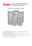
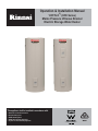
Operation & Installation Manual
®
‘HOTFLO ’ (HFE Series)
Mains Pressure Vitreous Enamel
Electric Storage Water Heater
This appliance shall be installed in accordance with:
•
•
•
•
•
Manufacturer’s Installation Instructions
Municipal Building Codes
AS/NZS 3000 Wiring Rules
AS/NZS 3500.4 Plumbing and Drainage
Any other local relevant Statutory Regulation
AS3498 Lic WMKA 21244
REGULATORY INFORMATION
Your Rinnai Hotflo Mains Pressure Vitreous Enamel Electric Storage Water Heater has been certified by relevant
plumbing and electrical authorities and the details are shown on data plate.
This appliance must be installed correctly by an authorised person and must conform to location regulations.
The installation must also comply with the instructions supplied by Rinnai.
Please keep this instruction booklet in a safe place for future reference.
Notice to Victorian Consumers
This appliance must be installed by a person licensed with the Plumbing Industry Commission.
Only a licensed person will have insurance protecting their workmanship.
So make sure you use a licensed person to install this appliance and ask for your Compliance Certificate.
For further information contact the Plumbing Industry Commission on 1800 015 129.
WARNINGS
Installation and service only by an authorised person.
•
DO NOT operate this system before reading the manufacturers instructions
•
DO NOT place articles on or against this appliance
•
DO NOT store chemicals or flammable materials near this appliance
•
DO NOT operate with panels or covers removed from this appliance
•
DO NOT activate heating elements unless cylinder is full of water
•
DO NOT touch any power supply cords, plugs or electrical conduits with wet hands.
Removal of access covers will expose 240V wiring. Access covers to be removed by authorised persons only.
This water heater is not intended to be operated or adjusted by young children or infirm persons. Young children
must be supervised to ensure they do not interfere with the water heater.
If the power supply cord, plug or electrical conduit to the water heater is damaged, it must be replaced by an
authorised person in order to avoid a hazard, using genuine replacement parts available from Rinnai.
Rinnai Australia
-i-
HOTFLO Electric Storage Water Heater Operating/Installation Manual
TABLE OF CONTENTS
REGULATORY INFORMATION.................................................................................................................................. i
WARNINGS ................................................................................................................................................................. i
Hydrogen Gas ........................................................................................................................................................ 1
Water Temperature ................................................................................................................................................ 1
IMPORTANT INFORMATION .................................................................................................................................... 1
SAFETY ...................................................................................................................................................................... 1
SAFETY DEVICES ................................................................................................................................................ 2
ANODE .................................................................................................................................................................. 2
WATER QUALITY.................................................................................................................................................. 2
TURNING ‘OFF’ THE WATER HEATING SYSTEM .............................................................................................. 2
TURNING ‘ON’ THE WATER HEATING SYSTEM................................................................................................ 2
HOW THE WATER HEATER WORKS .................................................................................................................. 2
TWIN ELEMENT MODEL ...................................................................................................................................... 2
REGULAR CARE................................................................................................................................................... 3
Over flow tray and drain ......................................................................................................................................... 3
Pressure and Temperature Relief (PTR) Valve ..................................................................................................... 3
Expansion Control Valve (ECV) if fitted ................................................................................................................. 3
SAVE A SERVICE CALL ....................................................................................................................................... 4
LACK OF HOT WATER OR NO HOT WATER ..................................................................................................... 4
HIGH ELECTRICITY BILLS ................................................................................................................................... 4
SERVICING AND REPAIR ......................................................................................................................................... 4
WATER HEATER VALVES DISCHARGING EXCESSIVELY ............................................................................... 5
SERVICE ............................................................................................................................................................... 5
INSTALLATION DIAGRAMS ................................................................................................................................. 6
Figure 1 - Typical Installation of Water Heater ..................................................................................................... 6
Figure 2 - Hot Water Plumbing System Example - No Temperature Limiting Device .......................................... 6
GENERAL INSTALLATION ....................................................................................................................................... 6
Figure 3 - Hot Water Plumbing System Example - with Temperature Limiting Device (TLD) .............................. 7
Figure 4 - Hot Water Plumbing Water Heater system Example - with Flow & Return Pipe Work ........................ 7
Figure 5 - Hot Water Plumbing System Example with Flow and Return Pipe Work and TLD ............................. 8
WATER HEATER LOCATION ............................................................................................................................... 8
WATER QUALITY.................................................................................................................................................. 9
HOT WATER STORAGE AND DELIVERY TEMPERATURES ............................................................................. 9
Storage Temperature ............................................................................................................................................. 9
Sanitary Fixtures Delivery Temperature................................................................................................................. 9
Water Pipes............................................................................................................................................................ 9
Electrical Supply................................................................................................................................................... 10
Valves and fittings ................................................................................................................................................ 10
PLUMBING CONNECTIONS............................................................................................................................... 11
PTR Valve Connection......................................................................................................................................... 11
Expansion Control Valve (ECV) ........................................................................................................................... 11
Drain Lines ........................................................................................................................................................... 11
ELECTRICAL CONNECTIONS .......................................................................................................................... 11
Figure 6 - Single and Twin Elements Wiring Diagrams .................................................................................. 12
Thermostat Setting............................................................................................................................................... 12
To fill and turn ‘ON’ the water heater ................................................................................................................... 13
To turn ‘OFF’ the water heater ............................................................................................................................. 13
Draining................................................................................................................................................................ 13
COMMISSIONING .................................................................................................................................................... 13
Figure 7 - Dimensional Drawing .......................................................................................................................... 14
SPECIFICATIONS .................................................................................................................................................... 14
Table 1 - Specifications .................................................................................................................................... 15
CONTACT INFORMATION ...................................................................................................................................... 18
Rinnai Australia
- ii -
HOTFLO Electric Storage Water Heater Operating/Installation Manual
SAFETY
Hydrogen Gas
If the hot water heater is not used for two weeks or more, a quantity of hydrogen gas, which is highly flammable,
may accumulate in the water heater. To dissipate this safety, it is recommended that a non electrically operated
hot tap be turned on for several minutes at a sink, or bath, but not at dishwasher or other appliance. During this
procedure there must be no smoking, open flame or any electrical appliance operating nearby. If hydrogen gas is
discharged through the tap, it will probably make a sound like air escaping.
Water Temperature
To meet regulatory requirements the temperature of stored water heater must not be less than 60°C.
The thermostat on your water heater is factory pre-set to 65°C which is suitable for the vast majority of domestic
applications.
The thermostat setting can be adjusted between 60°C and 75°C by an electrician or other suitably qualified trades
person.
NOTE
•
The thermostat setting must only be adjusted by an Electrician or other suitably qualified
trades person.
•
The access cover to the element and thermostat must only be removed by an Electrician or
other suitably qualified trades person.
IMPORTANT INFORMATION
Hot Water can cause scalds.
Children, disabled, and the elderly are at the highest risk
of being scalded.
Feel water temperature before bathing or showering.
Scalds from hot water taps can result in severe injuries
to young children.
Scalds can occur when children are exposed directly to
hot water when they are placed into a bath which is too
hot.
•
Do stay with children whenever
they are in the bathroom (Take the
phone off the hook).
•
•
Do take them out of the bathroom if
you need to answer the phone or
door.
•
•
Do test the temperature of the
water with your elbow before
placing your child in the bath.
•
Do make sure that the tap is turned
off tightly.
•
Do install a child proof tap cover
OR
•
Do install a child resistant tap.
DO
Rinnai Australia
Consider child-resistant taps or tap
covers, which prevent a small hand
being able to turn on the tap.
Consider installing tempering
valves or thermostatic mixing
valves which reduce the hot water
temperature delivered to taps. Your
local plumbing authority may
already require that these be fitted.
Contact your installer or local
plumbing authority if in doubt.
-1-
•
DON’T
DON’T leave a toddler in
the care of another small
child. The older child may
not have set the water
temperature to a safe
level.
HOTFLO Electric Storage Water Heater Operating/Installation Manual
IMPORTANT INFORMATION
SAFETY DEVICES
For safe operation this water heater is fitted with a combination Pressure & Temperature Relief (PTR) Valve, a
thermostat and an over-temperature cutout for each heating element.
• DO NOT tamper with or remove safety devices.
WARNING
• DO NOT operate this water heater unless all safety devices are fitted and in working order.
• DO NOT block or seal the PTR Valve and drain pipe.
ANODE
The water heater is fitted with a sacrificial anode to extend it's life. It will slowly dissipate whilst protecting the
cylinder. The life of the water heater may be extended by arranging for an authorised person to inspect the anode
and replace it if required. It is recommended that the anode be inspected at least every 5 years.
The factory fitted Rinnai anode is Magnesium based. This anode is suitable when the total dissolved solids (TDS)
content in the water supply does not exceed 600 mg/L, which is the case in most areas. In areas where the total
dissolved solids (TDS) content in the water supply exceeds 600 mg/L the Rinnai Aluminimum based alloy is
required.
WATER QUALITY
The water quality of most public supplies is suitable for the water heating system. The water quality from bore wells
is generally unsuitable for the water heating system. Refer to the 'Warranty Conditions' for water quality parameters
and how they affect the warranty conditions. If in doubt about the water quality, have it checked against the
parameters listed in the warranty conditions.
If sludge or foreign matter is present in the water supply, a suitable strainer filter should be incorporated in the water
supply to the system.
TURNING ‘OFF’ THE WATER HEATING SYSTEM
If you plan to be away for only a few nights, we suggest you leave the water heating system switched on. If it is
necessary to switch off the water heater, the switch is usually marked and located in the electricity meter box of the
dwelling.
TURNING ‘ON’ THE WATER HEATING SYSTEM
Switch on the electric supply to the heating element. The switch is usually marked and located in the electricity
meter box of the dwelling. Water heating will now occur as required. It may take a number of hours before hot water
is available.
HOW THE WATER HEATER WORKS
SINGLE ELEMENT MODEL
This model has one electric heating element with its own thermostat. A vitreous enamel lined steel cylinder stores
water which is heated by an heating element located at the base of the cylinder. Its own automatic thermostat
controls the water temperature. The water heater connects directly to the mains water supply.
The heating element can be connected to a Continuous or Off-Peak electricity supply. The continuous supply is
appropriate when the water heater capacity is less than the daily usage of hot water. The Off- Peak supply is
appropriate when the water heater capacity exceeds the daily usage of hot water. The Off-Peak supply allows
heating only for set periods and a volume of water sufficient for daily usage is heated during the set period and
stored. The Off-Peak supply is usually cheaper. Electricity supply types and tariffs vary according to the local
electricity authority.
TWIN ELEMENT MODEL
This model has two heating elements, each with its own thermostat. A vitreous enamel lined steel cylinder stores
water which is heated by a heating element located at the base of the cylinder and the other near the top. Its own
automatic thermostats control the water temperature.
The bottom heating element heats the whole contents of cylinder and Top heating element (booster) only operates
during the high demand periods to heat the upper portion of the contents of the cylinder.
The two heating element are wired for non-simultaneous operation, so that only one heating element can operate
at a time. The bottom heating element can be connected to an off-peak electricity supply, and the top heating
element to a continuous electricity supply.
Rinnai Australia
-2-
HOTFLO Electric Storage Water Heater Operating/Installation Manual
IMPORTANT INFORMATION
REGULAR CARE
Over flow tray and drain
The overflow tray and drain (if fitted) should be periodically checked to ensure there are no blockages.
Pressure and Temperature Relief (PTR) Valve
This valve is located near the top of the water heater and is essential for safe operation. It is normal for the valve
to release a small quantity of water through the drain line during heating. However, continuous leakage of water
from the valve and its drain line may indicate a problem with the water heater.
WARNING
• Never block the outlet of the PTR valve or its drain line for
any reason. The easing gear must be operated at least once
every six months or more frequently in areas with a high
incidence of water deposits. It is very important you raise
and lower the easing gear gently.
• Failure to do this may result in the water heater cylinder
failing or under certain circumstances, exploding.
WARNING
• If the valve does not discharge water when the easing gear
lever is lifted, or does not seal again when the easing gear
is closed, attendance by an authorised person must be
arranged without delay. The PTR valve is not serviceable.
Expansion Control Valve (ECV) if fitted
Operate the easing lever on the expansion control valve once every six months. It is very important you raise and
lower the lever gently.
Rinnai Australia
-3-
HOTFLO Electric Storage Water Heater Operating/Installation Manual
SERVICING AND REPAIR
Our Servicing network personnel are fully trained and equipped to give the best service on your Rinnai appliance.
If your appliance needs service, ring one of the service contact numbers on the back of this booklet.
The pressure and temperature relief valve and expansion control valve must be checked for performance or
replaced by an authorised person at intervals not exceeding 5 years or more frequently in areas where the water
is classified as scaling water (see ‘Water Quality’).
It is recommended that the sacrificial anode be inspected every 5 years or more frequently in areas where there is
a high incidence of water deposits.
If the electric conduit, power supply cord or plug to the water heater is damaged, they must be replaced by an
authorised person in order to avoid a hazard. The power supply cord and plug (if fitted) must be replaced by a
genuine replacement part available from Rinnai.
SAVE A SERVICE CALL
Check the items below before requesting Service. Service and parts charges may be incurred where it is found that
there is no fault with the water heater and the issue is related to the plumbing installation or is due to the failure of
water or electric supplies.
LACK OF HOT WATER OR NO HOT WATER
Is there electricity supply to the water heater?
QUESTION
•
Check that the isolating switch marked "HOT WATER" or "WATER HEATER" at the meter box is
switched on. Check also that any isolating switches installed near the water heater are switched
on.
•
Check the fuse or circuit breaker marked "HOT WATER" or "WATER HEATER" at the meter box.
Repeated failure of fuse or tripping of circuit breaker indicates a fault which must be investigated
by an authorised trades person.
Is your unit a Twin Element electric water heater?
QUESTION
•
A twin element model (non-simultaneous) must have a continuous electricity supply to the top
heating element. Check that this is the case.
Are you using more hot water than you think?
QUESTION
•
Often it is not realized how much hot water is actually used. This applies especially to showering.
Review hot water usage, especially the time taken for showering, and investigate the use of flow
control valves or Water saving shower roses.
Are water heater valves discharging excessively?
QUESTION
•
Refer to the section “Water heater valves discharging excessively”.
HIGH ELECTRICITY BILLS
If you think your electricity bill is too high, investigate the following:
•
You may be using more hot water than you think. This applies especially to showering. Review hot water
usage, especially the time taken for showering, and investigate the use of flow control valves or 'water saving'
shower roses. Investigate recent changes to hot water usage patterns.
•
Water heater valves may be discharging excessively. Refer to the section "Water heater valves discharging
excessively".
•
There may be hot water leakages in hot water pipes or taps. Have these checked and rectified by a plumber.
•
There may have been changes in electricity tariffs since your last bill.
If, after investigating the above, you still require assistance contact Rinnai.
Rinnai Australia
-4-
HOTFLO Electric Storage Water Heater Operating/Installation Manual
SERVICING AND REPAIR
WATER HEATER VALVES DISCHARGING EXCESSIVELY
Pressure and Temperature Relief (PTR) valve
It is normal and desirable that this valve allows a small quantity of water to be discharged during the heating cycle.
If it discharges more than a bucket of water during a 24 hour period or discharges continuously there may be
another problem.
If the valve dribbles continuously, try easing the valve gear for a few seconds as described under 'Regular Care'.
This may dislodge any foreign matter and alleviate the problem.
If the valve discharges at high flows, especially at night, it may be as a result of the water pressure exceeding the
design pressure of the water heater. Ask your installer to fit a Pressure Limiting Valve (PLV).
•
Never replace the PTR valve with one which has a higher pressure rating than is specified
for your water heater.
•
If the valve discharges hot water at high flows until the water heater is cold and then stops
discharging until the water reheats there may be a serious problem. Switch off the power
supply in the meter box (the switch marked ‘WATER HEATER’ or ‘HOT WATER’) or the
isolating switch installed near the water heater and contact Rinnai.
WARNING
Expansion Control Valve (ECV) - if fitted
It is normal and desirable that this valve allows a small quantity of water to be discharged during the heating cycle.
If it discharges more than a bucket of water during a 24 hour period or discharges continuously there may be
another problem.
If the valve leaks continuously, try easing the valve gear for a few seconds as described under 'Regular Care'. This
may dislodge any foreign matter and alleviate the problem. If this does not alleviate the problem contact Rinnai.
SERVICE
The system should be checked and serviced by an authorised person at least every 5 years.
The PTR valve must be replaced at intervals not exceeding five (5) years.
Rinnai has a service and spare parts network with personnel who are trained and equipped to give the best service
on Rinnai appliances.
Rinnai Australia
-5-
HOTFLO Electric Storage Water Heater Operating/Installation Manual
GENERAL INSTALLATION
This appliance shall be installed in accordance with:
•
Manufacturer's Installation Instructions
•
AS/NZS 3500.4
•
AS/NZS 3000 Wiring Rules
•
Local Plumbing, Water and Electrical Authority Regulations
•
Municipal Building Codes
•
Any other relevant Statutory Regulations
THIS APPLIANCE IS NOT SUITABLE FOR USE AS A DOMESTIC SPA POOL OR SWIMMING POOL HEATER.
INSTALLATION DIAGRAMS
7
8
6
9
1
DATA AND WARNING LABELS
10
2
LEFT COLD WATER INLET
Connection RP 3/4" / 20mm
3
ELEMENT+THERMOSTAT COVER - ELECTRICAL SUPPLY CONNECTION
Removal and connection by qualified persons only, in accordance with AS/NZS 3000
4
PTR VALVE DRAIN PIPE,
Copper only Drain in Accordance with AS/NZS 3500.4
5
ELEMENT+THERMOSTAT COVER (Twin element models only)
Removal by qualified persons only.
6
LEFT HOT WATER OUTLET
Connection RP 3/4" / 20mm, use a union connection and Insulate Hot water pipe
7
PTR VALVE CONNECTION
RP 3/4" / 20mm Use supplied PTR Valve with 1/2" Reducing Bush
8
ANODE CAP
9
DUPLICATE PTR VALVE CONNECTION (25 and 50 litre models only)
5
4
11
3
12
2
13
1
14
10
DUPLICATE HOT WATER OUTLET
11
DUPLICATE PTR VALVE DRAIN PIPE
12
DUPLICATE HOT WATER OUTLET
13
WATER HEATER SUPPORT
In accordance with AS/NZS 3500.4
14
SAFE TRAY+DRAIN
Optional in accordance with AS/NZS 3500.4
Valves with pressure ratings other than specified are unsuitable & must not be used.
NOTE
WATER HEATER - located closest to most frequently used outlet - Access for service in the
installed position.
Figure 1 - Typical Installation of Water Heater
KITCHEN
LAUNDRY
NON TEMPERED
SUPPLY
PTR VALVE
(Supplied) 850 kPa
or 1000 kPa
BATHROOM
ENSUITE
WATER
HEATER
ISOLATING VALVE
NON RETURN
VALVE
COLD
SUPPLY
PLV 500 kPa
(Not Supplied)
ECV (Not Supplied)
700 kPa or 850 kPa
Valves with pressure ratings other than specified are unsuitable & must not be used.
NOTE
Figure 2 - Hot Water Plumbing System Example - No Temperature Limiting Device
Rinnai Australia
-6-
HOTFLO Electric Storage Water Heater Operating/Installation Manual
GENERAL INSTALLATION
KITCHEN
TEMPERATURE
LIMITING DEVICE
(TLD)
NON TEMPERED
SUPPLY
PTR VALVE
(Supplied) 850 kPa or
1000 kPa
LAUNDRY
PLV (SUPPLIED)
500 kPa
NON RETURN
VALVE
NON RETURN
VALVE
TEMPERATURE
LIMITING DEVICE
(TLD)
BATHROOM
TEMPERED
Supply
ISOLATING VALVE
ENSUITE
NON RETURN
VALVE
WATER
HEATER
(OR)
ISOLATING VALVE
NON RETURN
VALVE
ISOLATING VALVE
NON RETURN
VALVE
COLD
Supply
COLD
Supply
PLV 500 kPa
(Not Supplied)
PLV
ECV
Water
Heater
ECV(Not Supplied)
700 kPa or 850 kPa
Valves with pressure ratings other than specified are unsuitable & must not be used.
NOTE
It may be a requirement that the hot and cold water supply pressures to a Temperature Limiting Device (TLD)
are equal. If this is the case, a Pressure Limiting Valve (PLV) with the same pressure rating as the PLV for
the hot water is required for the TLD as shown.
Figure 3 - Hot Water Plumbing System Example - with Temperature Limiting Device (TLD)
KITCHEN
PTR VALVE
LAUNDRY
(Supplied 850 kPa or
1000 kPa)
BATHROOM
ENSUITE
FLOW+RETURN PUMP
NON RETURN
VALVE
WATER
ISOLATING VALVE
ISOLATING VALVE
HEATER
ISOLATING VALVE
NON RETURN
VALVE
COLD
Supply
PLV 500 kPa
(Not Supplied)
ECV(Not Supplied)
700 kPa or 850 kPa
Valves with pressure ratings other than specified are unsuitable & must not be used.
NOTE
Figure 4 - Hot Water Plumbing Water Heater system Example - with Flow & Return Pipe Work
Rinnai Australia
-7-
HOTFLO Electric Storage Water Heater Operating/Installation Manual
GENERAL INSTALLATION
UNTEMPERED SUPPLY
KITCHEN
PTR VALVE
(Supplied 850 kPa or
1000 kPa)
LAUNDRY
TLD
BATHROOM
FLOW+RETURN PUMP
ENSUITE
NON RETURN
VALVE
ISOLATING VALVE
WATER
HEATER
ISOLATING VALVE
NON RETURN
VALVE
COLD
Supply
PLV 500 kPa
(Not Supplied)
ECV (Not Supplied)
700 kPa or 850 kPa
NOTE
WARNING
Valves with pressure ratings other than specified are unsuitable and must
not be used.
1.
2.
This schematic is an example only, variations may also be suitable.
Tempered water from a TLD cannot be re-circulated. The TLD must
be positioned in a dead leg, branching off the circulated hot water
flow and return pipe.
Figure 5 - Hot Water Plumbing System Example with Flow and Return Pipe Work and TLD
WATER HEATER LOCATION
All Rinnai mains pressure electric storage hot water systems have an ingress protection rating of IPX4 making them
suitable for internal or external installation.
The water heater should be placed as close as practicable to the most frequently used hot water outlet point or
points to minimize the delay time for hot water delivery. This will usually be the kitchen tap. For installations where
the distance between the water heater and the outlets is considerable, a flow and return system can be used which
minimize the waiting time for hot water delivery.
It is recommended that the water heater is installed at ground or floor level. It must be installed in a vertically upright
position. The water heater must be accessible without the use of a ladder or scaffold. It must not be installed in roof
spaces.
Ensure the pressure and temperature pressure relief (PTR) valve, front covers, thermostats and heating elements
have sufficient clearances and are accessible for service and removal.The information on the rating plates must
also be readable. Leave adequate distance above the water heater (preferably the height of the water heater itself)
so the sacrificial anode can be inspected and replaced via the top cover.
The water heater must be installed in freestanding mode on a level and stable base. For external installations, the
water heater should be mounted on a concrete base at least 50 mm thick or on well seasoned, evenly spread
hardwood slats with a thickness of at least 25 mm. Where property damage can occur as a result of water leakage,
the water heater must be installed with a safe tray (overflow tray) and drain in accordance with AS/NZS 3500.4.
Ensure the water heater does not stand on wet surfaces.
Rinnai Australia
-8-
HOTFLO Electric Storage Water Heater Operating/Installation Manual
GENERAL INSTALLATION
WATER QUALITY
The water quality of most public supplies is suitable for the water heater. Water quality from bore wells is generally
unsuitable. Refer to the ‘Warranty Conditions’ for water quality parameters and how they affect warranty. If in doubt
about water quality, have it checked against the parameters listed in the warranty conditions.
In a scaling water supply, calcium carbonate and possibly other compounds are deposited out of the water onto
any hot metallic surface and form a scale.
Scaling water is defined as having a total hardness in excess of 200 mg/litre (expressed as Calcium Carbonate) or
a Saturation Index in excess of +0.4. Scale deposits may form onto the metallic surfaces of the PTR valve and may
prevent it from operating properly. To prevent this, an expansion control valve (ECV) must be fitted on the cold
water line after the non-return valve in areas of scaling water. ECVs’ must be fitted in South Australia and Western
Australia to comply with local regulations.
Refer to the ‘Warranty Conditions’ for water quality parameters and how they affect warranty. If in doubt about
water quality, have it checked against the parameters listed in the warranty conditions. If sludge or foreign matter
is present in the water supply, a suitable strainer or filter should be incorporated in the water supply to the storage
cylinder.
Connection to a low pressure gravity or cylinder water supply
If the water heater is supplied by a low pressure gravity or cylinder water supply, the bottom of the supply cylinder
must be at least one meter above the highest hot water outlet and care must be taken to avoid air locks. Pipe sizing
and valve selection must be performed to allow for the water supply pressure.
HOT WATER STORAGE AND DELIVERY TEMPERATURES
Storage Temperature
AS/NZS 3500.4 conveys that hot water shall be stored at a minimum temperature of 60°C. The thermostat setting
on the storage water heater has been factory pre-set to 65°C to meet this requirement. The thermostat temperature
setting is adjustable to a maximum temperature setting of 75°C but this usually is not required.
WARNING
•
The thermostat settings must only be adjusted by an Electrician or other suitably qualified
trades person.
•
The access cover to the element and thermostat must only be removed by an Electrician or
other suitably qualified trades person.
•
DANGER: The operation of the thermal cut-out indicates a possibly dangerous situation.
DO NOT reset the thermal cut-out until the water heater has been serviced by a qualified
person.
Sanitary Fixtures Delivery Temperature
Water temperatures over 50°C can cause severe scalds. Children, disabled and the elderly are at the highest risk
or being scalded.
Local regulations and/or the requirements of AS/NZS 3500.4 must be considered regarding the temperature
limitations of hot water supplied to areas used primarily for personal hygiene. The temperature of is limited to 45°C
for early childhood centres primary and secondary schools and nursing homes or similar facilities for young, aged,
sick or people with disabilities and 50°C for all other buildings. To comply with these requirements, a temperature
limiting device, such as a tempering or thermostatic mixing valve, will be required on all 'new' installations.
Installers should explain to customers the merits of limiting the temperature of water supplied to areas used
primarily for personal hygiene for installations which are not classified as 'new'.
Figures 3 and 5 show the installation examples with Temperature Limiting Devices (TLD's).
Water Pipes
All hot water pipe work should be insulated with Polythene foam or equivalent insulation to optimize performance
and energy efficiency. Such insulation may also be mandatory under local regulations. Insulation must be
weatherproof and UV resistant if exposed.
Water pipe sizing should be performed in accordance with AS/NZS 3500.4.
To prevent damage to the water heater when attaching pipe clips or saddles to the jacket, it is recommended that
self drilling screws with a maximum length of 12mm are used. If drilling is required take extreme care not to
penetrate the inner cylinder. Damage to the inner cylinder is not covered under warranty.
Rinnai Australia
-9-
HOTFLO Electric Storage Water Heater Operating/Installation Manual
GENERAL INSTALLATION
Electrical Supply
Electrical connection must be carried out by a qualified person and in accordance with AS 3000 'Wiring Rules' and
local authority requirements.
A water heater not fitted with a power cord & plug must have the heating element connected to an independent,
fused, AC 240V 50 Hz power supply with an isolating switch installed at the switch board, which shall effectively
isolate all active supply conductors from the circuit and means for disconnection must be incorporated in the fixed
wiring in accordance with the wiring rules. Ensure the household wiring to the system is capable of withstanding
the system electrical load (refer to Specifications - Table 1 for electrical load details).
A water heater fitted with a power cord & plug must be plugged into a switched, AC 240V AC, 50 Hz mains power
outlet rated at 10 Amps. A power cord is available for replacement. Please contact Rinnai Customer Care for part
number.
The power supply to a single element model can be Off-Peak (overnight), Extended Off-Peak (overnight and day),
or Continuous (day).
The power supply to a twin element model should be Off-peak (overnight) to bottom heating element and
Continuous to the top heating element.
Check the avaible tariffs with the local electricity supplier. The Off-Peak (overnight) is usually the most economical
for the customer.
Valves and fittings
Valves & fittings supplied with water heater are placed in the Styrofoam packaging base during transit.
The pressure ratings of valves are shown in Table 1.
1. A combined Pressure & Temperature (PTR) Relief Valve (supplied). This valve is fitted at the top of the
storage cylinder. The PTR valve is a safety device and it is mandatory that it is fitted by the installer in all
installations.
2. Three brass plugs are supplied to plug the unused PTR, hot and cold connections.
3. A reducing bush is supplied to enable fitment of the ¾" PTR valve connection to the ½" cylinder connection.
4. 500 kPa PLV is supplied with some models as listed in Table 1. It must be fitted if the Mains Pressure exceeds
the limits shown in Table 1. If the mains pressure is within the limits shown in Table 1 fitment of the PLV is
optional. However, it is recommended that the PLV is fitted in all installations as it aids water and energy
conservation.
5. A cold water Expansion Control Valve (ECV) (not supplied) must be fitted in areas with a ‘scaling’ water
supply, having a total hardness in excess of 200 mg/litre (expressed as Calcium Carbonate) or Saturation
Index in excess of + 0.4 as detailed under Water Quality, if required. ECVs’ must be fitted in South Australia
and Western Australia to comply with local regulations. For pressure setting information refer Table 1.
6. A stop cock and non return valve (not supplied). Combination valves incorporating these functions (such as
'Duo' or 'Trio' valves) are suitable. These are fitted to the cold water supply to the water heater.
7. A temperature limiting device (not supplied), such as a tempering valve if required.
WARNING
Rinnai Australia
Valves with pressure ratings other than those listed above must not be used.
- 10 -
HOTFLO Electric Storage Water Heater Operating/Installation Manual
GENERAL INSTALLATION
PLUMBING CONNECTIONS
Refer to Figure 1 for the location and specification of each plumbing connection to the water heater.
The water heater has 'dual handed' PTR valve, cold supply and hot outlet connections. The brass plugs (supplied)
are used to plug unused connections.
NOTE
Models: HFE25S / HFE50S have foam caps supplied. These MUST be used to cover up these
brass plugs to prevent heat losses.
PTR Valve Connection
The PTR Valve must be fitted before the water heater is operated. Before installation, ascertain that the probe is
straight and undamaged. Seal the thread with Teflon tape - never use hemp.
Make certain the edge of the Teflon tape does not protrude past the end of the thread. Screw the reducing bush
supplied into the fitting on the water heater marked PTR Valve, then screw the PTR valve into the reducing bush.
Leave the valve outlet pointing down. Tighten the valve using the spanner flats - never use the valve body.
Expansion Control Valve (ECV)
The expansion control valve (if used) must always be installed after the non return valve and be the last valve
installed before the water heater (Refer to Figures 2 - 5).
Drain Lines
Copper drain lines (½” or DN15) must be fitted to the PTR valve and ECV (if fitted). The water may drip from the
discharge pipe of the pressure relief device and this must be left open to atmosphere. The length should be as
short as possible on a continuous downward slope with no restrictions and is a frost-free environment. Length
should not exceed 9 metres with no more than three right angle bends. In areas where water pipes are prone to
freezing, drain lines must be insulated and not exceed 300mm in length. In this case the drain line must discharge
into a tundish through an air gap of between 75mm and 150 mm.
The outlet of drain lines must be positioned so that they are readily visible but not cause injury, damage or
nuisance.
ELECTRICAL CONNECTIONS
The water heater must be filled with water prior to connection to the power supply.
CAUTION
WARNING
Disconnect all power prior to installation and commissioning. This appliance is designed for
single phase 240 Volts, AC mains electrical operation. All electrical connections must be made
by an authorised person and must comply with all local electrical supply regulations and
AS/NZS 3000.
s
The household wiring to the heater must be capable of withstanding the appliance load.
NOTE
Electrical access is via a 20 mm hole beneath the element cover for mounting with an approved weatherproof
electrical conduit nipple. For entry to the element cover remove the two fixing screws. Connect all ACTIVE and
NEUTRAL wires in accordance with the wiring diagram which is also included at the rear of the element access
cover. Ensure the incoming EARTH wire is securely fixed to the earth post provided on the heater case. Inspect
and ensure that all wiring links are secure prior to fixing the access cover and turning the POWER ON.
To ensure the Over-temperature and Energy Cutout is set, press the (red) 'reset' button on the Thermostat.
Rinnai Australia
- 11 -
HOTFLO Electric Storage Water Heater Operating/Installation Manual
GENERAL INSTALLATION
SINGLE ELEMENT
3
ST1204113
TWIN ELEMENT
1
3
4
ST2207233
1
4
5
2
5
2
TOP ELEMENT
Earth
Active - A
Neutral - N
3
ST1204113
1
4
5
2
BOTTOM ELEMENT
Earth
Continuous - A
Off Peak - A
Neutral - N
Figure 6 - Single and Twin Elements Wiring Diagrams
Thermostat Setting
The thermostat is adjustable from 60°C to 75°C. Turning the adjustment knob anticlockwise decreases the
temperature setting and turning it clockwise increases the temperature setting. Rinnai advice that the thermostat
be set at 65°C, this temperature is sufficient for most users. Ensure the power supply is switched OFF before
removing the access cover to the element and thermostat.
WARNING
Rinnai Australia
•
The access cover to the element and thermostat must only be removed by an Electrician or
other suitably qualified trades person.
•
The thermostat setting must only be adjusted by an electrician or other suitably qualified
trades person.
•
After adjustment, press the (red) ‘Reset’ Button on the thermostats to ensure the overtemperature and energy cut-out is set.
- 12 -
HOTFLO Electric Storage Water Heater Operating/Installation Manual
COMMISSIONING
Commissioning and draining activities must be carried out by an authorised person.
To fill and turn ‘ON’ the water heater
•
WARNING
Do not switch on the electric power supply until the water heater is filled completely with
water.
•
Open all hot water taps in the house, including the shower.
•
Open the cold water isolation valve to water heater. Air will now be forced out of the taps.
•
Close each tap when water runs freely without air bubbles.
•
Check all plumbing connections and pipe work for water leaks.
•
Switch on the electric power supply.
To turn ‘OFF’ the water heater
It may be necessary to turn off a water heater after installation and commissioning, for example during building
activities or if the premises are vacant.
To turn ‘OFF’ the water heater:
•
Switch off the electricity supply at the isolating switch to the water heater.
•
Unplug the power supply cord from the power outlet (only for models fitted with power supply cord).
•
Close the cold water isolation valve at the inlet to the water heater.
Draining
To drain the water heater:
•
Turn off the water heater.
•
Close all hot water taps.
•
Operate the PTR valve release - gently. Operating the PTR valve release will relieve the pressure in the
water heater.
•
Undo the cold water inlet union. Attach a hose to the water heater side of the union. Let the other end of
the hose go to a drain.
•
Operate the PTR valve again. This allows air into the water heater and will result in water draining through
the hose.
Rinnai Australia
- 13 -
HOTFLO Electric Storage Water Heater Operating/Installation Manual
SPECIFICATIONS
B
C
OUTLETS
P&TR
A
D
G
INLETS
E
F
Figure 7 - Dimensional Drawing
All Dimensions are in (mm)
Models
A
B
C
D
E
F
G
HFE25S
452
490
415
297
153
80
-
HFE50S
694
490
415
524
158
80
-
HFE80S
900
590
515
683
225
155
-
HFE125S
1245
590
515
1020
225
155
-
HFE160S
1530
590
515
1310
225
155
-
HFE200S
1825
590
515
1605
225
155
-
HFE250SSL
1475
700
625
1215
90
50
-
HFE315SSL
1762
700
625
1430
90
50
-
HFE400S
1820
760
685
1512
260
155
-
HFE160T
1530
590
515
1310
225
155
946
HFE250T
1475
700
625
1215
90
50
978
HFE315T
1762
700
625
1430
90
50
1193
HFE400T
1820
760
685
1512
260
155
1224
Rinnai Australia
- 14 -
HOTFLO Electric Storage Water Heater Operating/Installation Manual
Rinnai Australia
HFE160S18
HFE160S24
HFE160S36
HFE160S48
- 15 3600
4800
3600
4800
315
400
400
250
315
3600
4800
1800
2400
3600
4800
2400
3600
4800
3600
4800
3600
4800
3600
4800
3600
4800
3600
4800
3600
4800
1800
2400
3600
4800
1800
2400
3600
4800
1800
2400
3600
4800
1800
2400
3600
4800
1800
2400
3600
4800
1800
2400
3600
4800
850
1000
850
1000
700
850
Heating
Expansion
Cylinder PTR Valve
Elements
Control Vale
Rated
Pressure
Available
(ECV)
Pressure
Rating
Watts (W)
Pressure
(kPa)
(kPa)
- BOTTOM
Rating (kPa)
550
680
(1)
500 (1)
500
Recommended
Pressure Limiting
Valve (PLV)
Pressure Rating
(kPa)
ECV FITTED
Fit Pressure
Limiting Valve
(PLV) if mains
pressure
exceeds: (kPa)
680
800
(1)
500 (1)
500
Recommended
Pressure
Limiting Valve
(PLV) Pressure
Rating (kPa)
ECV NOT FITTED
Fit Pressure
Limiting Valve
(PLV) if mains
pressure
exceeds: (kPa)
75°C
75°C
3/4"
(20 mm)
3/4"
(20 mm)
IPX4
IPX4
Ingress
Thermostat
Hot&Cold
Protection
setting
Water
Rating
(Max)
Connections
(AS 1939)
1.5
1.5
Electrical
power
cord
length
(metres)
HF - Hotflo
HF - Hotflo
Legend:
HF E 25 S 18P
HF E 160 T 18
E - Electric
Cylinder
E - Electric
Cylinder
160 Rated
Capacity
of the
cylinder
25 Rated
Capacity
of
cylinder
S - Single 18 - First two
P - Plug and
heating
digits of
Cord
element
heating
element
rating eg: 18
= 1800
Watts
18 - First two digits of heating
T - Twin
element rating eg: 18 = 1800
heating
Watts
element
Example:
Note: A 500 kPa PLV is supplied with HFE40S, HFE400S or HFE400T. It is not supplied with other models. A PLV must be fitted if the Mains Pressure exceeds the limits shown. If the mains pressure is
within the limits shown fitment of the PLV is optional. However, it is recommended that the PLV is fitted in all installations as it aids water and energy conservation.
(1)
-
-
-
160
HFE125S18
HFE125S24
HFE125S36
HFE125S48
-
250
125
HFE80S18
HFE80S24
HFE80S36
HFE80S48
-
-
80
HFE50S18P
HFE50S24P
HFE50S36
HFE50S48
-
200
50
HFE40S18
HFE40S24
HFE40S36
HFE40S48
-
1800
2400
3600
4800
40
HFE25S18P
HFE25S24P
HFE25S36
HFE25S48
Heating
Elements
Available
Watts (W)
- UPPER
160
25
Model No's.
HFE160T18
HFE160T24
HFE160T36
HFE160T48
HFE200S24
HFE200S36
HFE200S48
HFE250SSL36
HFE250SSL48
HFE250T36
HFE250T48
HFE315SSL36
HFE315SSL48
HFE315T36
HFE315T48
HFE400SS36
HFE400SS48
HFE400T36
HFE400T48
Rated
Capacity/Hot
Water
Delivery (L)
SPECIFICATIONS
Table 1 - Specifications
HOTFLO Electric Storage Water Heater Operating/Installation Manual
THIS PAGE IS INTENTIONALLY BLANK
Rinnai Australia
- 16 -
HOTFLO Electric Storage Tanks Operating/Installation Manual
THIS PAGE IS INTENTIONALLY BLANK
Rinnai Australia
- 17 -
HOTFLO Electric Storage Tanks Operating/Installation Manual
CONTACT INFORMATION
Australia Pty. Ltd.
Internet: www.rinnai.com.au E-mail: [email protected]
ABN 74 005 138 769
Head Office
National Help Line
Tel: 1300 555 545* Fax: 1300 555 655*
Spare Parts & Technical Info
Tel: 1300 366 388* Fax: 1300 300 141*
10-11 Walker Street,
Braeside, Victoria 3195
P.O. Box 460
Tel: (03) 9271 6625
Fax: (03) 9271 6622
*Cost of a local call higher from mobile or public phones.
Rinnai has a Service and Spare Parts network with personnel who are fully trained
and equipped to give the best service on your Rinnai appliance. If your appliance
requires service, please call our National Help Line. Rinnai recommends that this
appliance be serviced every 2 years.
18
RA TSD 05-010 Hotflo Electric WH Op/Ins Man. Issue 7: 19/9/13