1
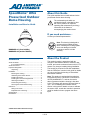
About this Guide
SpeedDome® Ultra
Pressurized Outdoor
Dome Housing
This guide explains how to install and service the
pressurized outdoor dome housing.
The exclamation point within an
equilateral triangle is intended to alert
the user to presence of important
operating and maintenance (servicing)
instructions in the literature
accompanying the outdoor dome.
Installation and Service Guide
If you need assistance...
Contact your Sales Representative.
Note: This housing is designed to
operate with the bubble pointing
down. Installing the housing upside
down can damage its internal
equipment, and will void the
warranty.
RHODULP-01 (clear bubble)
RHODULP-02 (smoked bubble)
About the Product
Contents
The outdoor housing is pressurized with dry
nitrogen to eliminate the effects of moisture, dust,
insects, and corrosive exhaust fumes on the CCTV
camera. Dry nitrogen is added during installation.
About this Guide ............................................................ 1
If you need assistance... ......................................... 1
About the Product .......................................................... 1
Important Safeguards .................................................... 2
Unpacking .............................................................. 2
Installation ..................................................................... 3
Mounting the Housing............................................. 3
Calibrating the Pressure Sensor............................. 4
Installing the Dome................................................. 5
Installing the Desiccant Bag Bracket ..................... 5
Attaching the Bubble .............................................. 6
Pressurizing the Housing........................................ 6
Servicing the Pressurized Housing......................... 7
Reference ...................................................................... 8
Wiring Color Code .................................................. 8
Exploded View of Housing...................................... 9
Specifications .............................................................. 10
Declarations................................................................. 10
The housing is pre-wired for RS-422 Installations.
See the “Reference” section in this guide for details
on how to configure the housing on SensorNet/
Manchester networks.
Note: This product is equipped with an absolute
low-pressure sensor. The sensor is connected to
IO PCB ALARM INPUT 1 and can be used to
detect if pressure inside the housing is less than
0.5psi. The sensor will open at 0.5psi and close at
1psi. See “Calibrating the Pressure Sensor”
section in this guide for details on how to calibrate
the sensor. Also, consult the controller’s operation
guide for details on how to program the alarm
input.
© 2005 Sensormatic Electronics Corp.
SPEEDDOME ULTRA PRESSURIZED OUTDOOR DOME HOUSING
INSTALLATION AND SERVICE GUIDE
8200-0462-01, REV. B
1 of 10
8. Mounting - This housing must be properly
secured to a supporting structure capable of
sustaining the weight of the unit. Accordingly:
Important Safeguards
CAUTION: The housing is a pressurized
enclosure. As such, certain care is
required for the safe use of the product.
a. The installation should be made by a
qualified installer and be in compliance with
local codes.
1. Inspect the housing upon opening the
box. Ensure it was not damaged
during shipping. Immediately replace
housings that have been cracked or
show signs of damage.
b. Select suitable installation hardware for the
mounting surface and weight of the unit and
periodically examine the housing and
supporting structure to ensure the integrity of
the installation. Otherwise, the housing could
separate from the support structure and fall,
causing damage or injury.
2. Always use safety goggles when
servicing the housing.
3. Never use an unregulated gas supply
to pressurize the housing. The valve
should be regulated with a maximum
of 10psi output.
Unpacking
Unpack carefully. Electronic components can be
damaged if improperly handled or dropped. If an
item appears to have been damaged in shipment,
replace it properly in its carton and notify the
shipper.
4. PRESSURIZE USING DRY
NITROGEN GAS ONLY!
5. Periodically examine the housing and
structure to which it's attached. If any
wear is noticed, replace immediately.
Be sure to save:
1. The shipping carton and packaging material.
They are the safest material in which to make
future shipments of the equipment.
Additional Safeguards
1. Read Instructions – Read all safety and
operating instructions before operating the unit.
2. These instructions.
2. Retain Instructions – Retain safety and
operating instructions for future reference.
WARNING! TO REDUCE THE
RISK OF ELECTRICAL SHOCK,
DO NOT EXPOSE COMPONENTS
TO WATER OR MOISTURE.
3. Heed Warnings – Heed all warnings on the unit
and in the operating instructions.
4. Follow Instructions – Follow all operating and
user instructions.
5. Electrical Connections – Only a qualified
electrician should make electrical connections.
6. Attachments – Attachments not recommended
by the product manufacturer may cause
hazards.
7. Cable Runs – All cable runs must be within
permissible distance.
SPEEDDOME ULTRA PRESSURIZED OUTDOOR DOME HOUSING
INSTALLATION AND SERVICE GUIDE
8200-0462-01, REV. B
2 of 10
6. Loop the safety cable exiting the top of the
housing over one of the set screws on the
bayonet coupling and connect cables exiting
housing and pipe together using the two screwdown connectors supplied.
Installation
Note: This section assumes cables are routed to
the mounting site.
Tools Required:
-
.100in flat head screwdriver
-
Phillips-head torque screwdriver
-
7/16in socket
-
Nitrogen tank kit RHONKIT or equivalent
99.998% N2.
Safety
Cable
Connectors
Mounting the Housing
1. Carefully remove the housing from the package.
Ensure all parts are present.
Note: The standard model is a pendant mount
housing. A 1.5in NPT housing coupling is
provided for use with a standard 1.5in (NPT)
pipe.
Power
2. Install pendant pipe mount or wall mount
bracket in the desired location.
Ensure the mount is properly secured
to a supporting structure capable of
rigidly holding the weight of the
housing once assembled.
1
Camera Power (24Vac)
White
2
Camera Power
(earth ground)
Red
3
Camera Power (24Vac)
Black
Data
1
RS-422 Rx+ (SensorNet)
Orange
Green
2
RS-422 Rx– (SensorNet)
3. Remove cover from pipe threads and ensure
threads are clean and rust free.
3
RS-422 Tx+
Yellow
4
RS-422 Tx–
Brown
4. Loosen three set screws and detach the
bayonet coupling from the housing.
5
SensorNet
(See Note)
6
SensorNet
(See Note)
Bayonet
Coupling
Note: The I/O circuit board wiring factory set up is
for RS-422. For SensorNet (or Manchester)
installations, disconnect orange and green wires
from P1-1 and P1-2 respectively, and reconnect
these wires to P1-5 and P1-6.
Set Screws
7. Reattach the housing to the bayonet and secure
the three captive screws.
Housing
CAUTION: Do not over tighten
screws. Tighten them only to the point
at which the gap closes between the
ring and the housing top.
5. Apply pipe sealing tape to the pipe threads and
thread the bayonet onto the mount.
Apply pipe sealing
tape here.
SPEEDDOME ULTRA PRESSURIZED OUTDOOR DOME HOUSING
INSTALLATION AND SERVICE GUIDE
8200-0462-01, REV. B
3 of 10
Calibrating the Pressure Sensor
8. Remove the bubble assembly from the housing
to access the I/O circuit board inside the
housing.
The housing includes an absolute pressure sensor
that must be calibrated, at the site, just before
installation.
a. Loosen the nine captive screws on the ring
next to the bubble. Do not to back screws all
the way out.
1. To access the pressure sensor, pull on the dust
cover to remove the I/O circuit board from base.
b. Twist the bubble counter clockwise to
remove.
Green
LED
Calibration
Button
Loosen screws, do
not remove them.
Remove the
bubble by
twisting
counterclockwise.
Dust
Cover
I/O Circuit
Board
2. Apply power to the housing and wait about 30
seconds for the green LED to start blinking.
3. Press the calibration button until the LED goes
out.
4. Snap the I/O circuit board back into its installed
position and remove the dust cover.
SPEEDDOME ULTRA PRESSURIZED OUTDOOR DOME HOUSING
INSTALLATION AND SERVICE GUIDE
8200-0462-01, REV. B
4 of 10
Installing the Dome
Installing the
Desiccant Bag Bracket
Connect the dome camera by aligning the
protrusion on the dome with the protrusion on the
mounting base (or white mark on the I/O board).
Then turn the dome clockwise to lock it.
Two desiccant bag brackets, each with two
desiccant bags, are installed in the housing to
absorb moisture after the purge process.
Note: At this point, the dome should begin its
homing routine. During this routine, the camera
lens moves up into the housing, down to the floor,
pans slowly, and moves up to its home position.
The controller can then be used to call up and
control the dome.
Before closing the bubble:
1. Remove a desiccant bag bracket from the
sealed plastic bag.
2. Pull the blower bracket away from the housing,
and slide the desiccant bag bracket behind it as
shown until the top of the bracket snaps behind
the lip in the blower bracket.
3. Repeat for the second desiccant bag bracket.
White mark
on I/O board
Brackets
installed.
Turn dome
clockwise to
lock.
SPEEDDOME ULTRA PRESSURIZED OUTDOOR DOME HOUSING
INSTALLATION AND SERVICE GUIDE
8200-0462-01, REV. B
5 of 10
Attaching the Bubble
Pressurizing the Housing
1. Line up tabs in the bubble assembly with the
slots in the housing.
Before You Begin
CAUTION:
Have the following on hand:
-
Inspect the O-ring gasket/bubble
to ensure no debris affects the
seal.
-
-
Ensure the lanyard does not
interfere with the bubble assembly.
A tank of dry nitrogen. Dry nitrogen is readily
available. To obtain supplies, check with a
medical or industrial gas provider. If the tank is
to be carried transported, a 40 cubic foot tank is
recommended.
WARNING! Handle the tank with
care. Although nitrogen is an inert
gas, the tank is highly pressurized
and if the valve or regulator is
damaged the tank could be
dangerous.
2. Turn the bubble assembly clockwise to lock it.
-
A regulator on the tank. Nitrogen tanks have a
standard 580 fitting. However, a regulator is
required.
-
A hose with an air chuck to connect the
regulator to the housing’s air intake valve.
The intake valve (also called a purge,
Schraeder, or dill valve) is similar to the intake
valve on a bicycle tire. To connect the regulator
to the purge valve on the housing, a hose is
needed with a ¼-inch barb on one end and an
air chuck on the other. The barb connects to the
regulator on the tank; the chuck connects to the
purge valve on the housing.
The American Dynamics product code for the
Nitrogen kit (Nitrogen Tank, Hose, and Regulator)
is RHONKIT.
3. Tighten the screws in the order shown below.
CAUTION: Tighten each screw to 12 in-lbs
using a torque screwdriver.
3
1
5
8
7
6
9
4
2
SPEEDDOME ULTRA PRESSURIZED OUTDOOR DOME HOUSING
INSTALLATION AND SERVICE GUIDE
8200-0462-01, REV. B
6 of 10
Servicing the Pressurized
Housing
Purge Procedure
1. Set the regulator gauge to 10psi.
When servicing the pressurized housing includes
the removal of the bubble assembly, desiccant
bags in the desiccant bag holder must be replaced
before reassembly. Two desiccant bag kits (part
number 0351-0207-01) provide the four
replacement bags required.
2. Fill the housing with dry nitrogen.
Before filling, ensure the two vent
holes between the top of the housing
and the black cap are free of ice or
debris.
Nitrogen might leak through the bubble
gasket when the pressure inside the
housing exceeds 5psi.
For regions that approach the high end of the
housing’s operating temperature range of 50°C:
It is recommended that the technician have
available both the desiccant bags kits mentioned
above, as a well as a replacement bubble. On rare
occasions, a new bubble may be required to
properly re-seat the bubble trim ring assembly. The
clear bubble (part number RCPFD8-CO) and
smoked bubble (part number RCTPFD8-CO) are
available for ordering.
a. Place the air chuck on the housing’s intake
valve and press down on the chuck to fill the
housing with dry nitrogen. Air escapes
through the two vent holes in the black cap
once the pressure inside the housing
exceeds 7psi. Continue filling for at least two
minutes after air escapes.
b. Place a pressure gauge on the intake valve
to verify pressure is between 3 to 5psi.
Intake valve
Vent hole
3. Purge nitrogen as follows:
a. Press the intake valve to release nitrogen
from the housing. Continue pressing until air
no longer rushes from the valve.
b. Re-fill the housing with dry nitrogen.
Continue filling for at least 10 seconds after
the vent holes release air.
c. Repeat steps (a) and (b) another three times.
d. Once purging is complete, place a pressure
gauge on the intake valve to verify pressure
is between 3 to 5psi.
Note: A peculiar sound may be heard when the
overpressure sensor opens.
SPEEDDOME ULTRA PRESSURIZED OUTDOOR DOME HOUSING
INSTALLATION AND SERVICE GUIDE
8200-0462-01, REV. B
7 of 10
Power (Euro Style Connector P7)
Reference
Wiring Color Code
Wiring Color Code for Power and Control
Inputs (outside of housing)
1
Camera Power (24Vac)
Black
2
Earth Ground
Red
3
Camera Power (24Vac)
White
Control (Euro Style Connector P1)
Power
1
RS-422 Rx+ (SensorNet)
Orange
Green
2
RS-422 Rx– (SensorNet)
1
Camera Power (24Vac)
Black
3
RS-422 Tx+
Yellow
2
Earth Ground
Red
4
RS-422 Tx–
Brown
3
Camera Power (24Vac)
White
5
SensorNet/Manchester+
Orange
6
SensorNet/Manchester–
Green
Data
1
RS-422 Rx+ (SensorNet)
Orange
2
RS-422 Rx– (SensorNet)
Green
Wiring Color Code for Power and Control
Inputs (on pressure sensor circuit board)
3
RS-422 Tx+
Yellow
4
RS-422 Tx–
Brown
5
SensorNet
(See Note)
6
SensorNet
(See Note)
Note: This board is not accessible to the installer.
It is between the housing and the fan/heater
brackets.
Power and Control Leads
Note: The I/O circuit board wiring factory set up is
for RS-422. For SensorNet (or Manchester)
installations, disconnect orange and green wires
from P1-1 and P1-2 respectively, and reconnect
these wires to P1-5 and P1-6.
Wiring Color Code for Power and Data Inputs
(on I/O circuit board)
Pin 1
Pin 1
Pin 1
P3
P7
P8
I/O BOARD
P4
1
Camera Power
(earth ground)
Red
2
Camera Power (24Vac)
White
3
Accessory Power (24Vac)
Black
4
RS-422 Rx+ (SensorNet)
Orange
5
RS-422 Rx– (SensorNet)
Green
6
RS-422 Tx+
Yellow
7
RS-422 Tx–
Brown
8
Low Pressure Alarm
White/Black
9
Low Pressure Alarm
White/Red
Pin 1
P1
1
JW1
JW1 Terminations
PINS
FUNCTION
1-2
Unterminated
2-3
Terminated
SPEEDDOME ULTRA PRESSURIZED OUTDOOR DOME HOUSING
INSTALLATION AND SERVICE GUIDE
8200-0462-01, REV. B
8 of 10
Exploded View of Housing
Parts List
1. Pressured Sealed Housing
2. Housing Coupling
3. Housing Packet
a. Screw down connectors (2)
b. Mounting 8 x 32 x 1/2in Mounting Screws (4)
c. #8 star washers (4)
d. Pin shunts (2)
e. Humidity strip
f. Instruction Manual
Item
No.
1
2
3
4
n/s
n/s
5
n/s
7
n/s
8
9
10
11
12
13
14
15
16
17
18
19
20
21
22
23
24
25
n/s
n/s
n/s
Description Part No.
25W Heater w/leads
Housing Top
Dome Support Ring
Captive Screw
Captive Screw Spring
Captive Screw Retainer
Clear Dome Bubble RCPFD8-CO
Smoked Dome Bubble RCTPFD8-CO
PFD8 Tinted Dome
Main Housing Bracket
Main Housing 10 x 32 x 1/2in bolts
Housing Fan
1/4 x 20 Set bolts
Black Plastic Housing Cover
4.50in O-ring
Inner Sealing Plate
Housing Mounting Coupling
Main Bracket Standoffs
1/4 Lock Washers
1/4 Flat Washers
PC8
5-7psi Release Valve
Schraeder Valve
Housing Coupling
Schraeder Valve Grommet
Housing Gasket
8x32x1/2in Flat Head
Hermetic Connector
Desiccant Bag Kit P/N 0351
External Leads to Hermetic Connector
Hermetic to PCB Cable Assembly
Housing Lanyard
SPEEDDOME ULTRA PRESSURIZED OUTDOOR DOME HOUSING
INSTALLATION AND SERVICE GUIDE
Qty
2
1
1
9
9
9
1
1
1
3
2
3
1
1
1
1
3
3
3
1
1
1
1
1
1
3
1
2
1
1
1
8200-0462-01, REV. B
9 of 10
EQUIPMENT MODIFICATION CAUTION: Equipment
changes or modifications not expressly approved by
Sensormatic Electronics Corporation, the party responsible for
FCC compliance, could void the user's authority to operate the
equipment and could create a hazardous condition.
Specifications
Electrical
Power input............................................... 24vac, Class 2
Housing .................................................... 75W @ 24Vac
Heaters (2) ................................................... 25W each
Blowers (2) ................................................ 0.84W each
Input connectors:
Power connector ......................................... 3 positions
Data connector............................................ 4 positions
Video..................................................................... BNC
Environmental
Operating Temperature ..... –40° to 50°C (–40° to 122°F)
Relative Humidity:.................... 0 to 90% non-condensing
Mechanical
Height ......................................................32.5cm (12.8in)
Width ..........................................................30cm (11.4in)
Depth .......................................................40.9cm (16.1in)
Weight .......................................................... 3.6kg (8 lbs)
Declarations
Regulatory Compliance
EMC........................................................47 CFR, Part 15
ICES003 Class A
EN 61000-6-1; 2001
EN50130-4;1996 /A1: 1998/A2: 2003
SAFETY.................................. IP67 (Standard EN60529)
IEC 60950
UL 2044
CanCSA-C22.2 No. 1
Other Declarations
Thank you for using American Dynamics products. We
support our products through an extensive and worldwide
network of dealers. The dealer, through whom you originally
purchased this product, is your point of contact if you have a
need for service or support. Our dealers are fully empowered
to provide the very best in customer service and support.
Dealers should contact American Dynamics at
(800) 507-6268 or (561) 912-6259 or on the web at
www.americandynamics.net.
WARRANTY DISCLAIMER: Sensormatic Electronics
Corporation makes no representation or warranty with respect
to the contents hereof and specifically disclaims any implied
warranties of merchantability or fitness for any particular
purpose.
NOTICE: The information in this manual was current when
published. The manufacturer reserves the right to revise and
improve its products. All specifications are therefore subject to
change without notice.
LIMITED RIGHTS NOTICE: For units of the Department
of Defense, all documentation and manuals were developed at
private expense and no part of it was developed using
Government Funds. The restrictions governing the use and
disclosure of technical data marked with this legend are set
forth in the definition of “limited rights” in paragraph (a) (15)
of the clause of DFARS 252.227.7013. Unpublished - rights
reserved under the Copyright Laws of the United States.
TRADEMARK NOTICE: American Dynamics and
Sensormatic are trademarks or registered trademarks of
Sensormatic Electronics Corporation. Other product names
mentioned herein may be trademarks or registered trademarks
of Sensormatic or other companies.
COPYRIGHT: Under copyright laws, the contents of this
manual may not be copied, photocopied, reproduced,
translated or reduced to any electronic medium or machinereadable form, in whole or in part, without prior written
consent of Sensormatic Electronics.
MDR 1/05
FCC COMPLIANCE: This equipment complies with Part 15
of the FCC rules for intentional radiators and Class A digital
devices when installed and used in accordance with the
instruction manual. Following these rules provides reasonable
protection against harmful interference from equipment
operated in a commercial area. This equipment should not be
installed in a residential area as it can radiate radio frequency
energy that could interfere with radio communications, a
situation the user would have to fix at their own expense.
SPEEDDOME ULTRA PRESSURIZED OUTDOOR DOME HOUSING
INSTALLATION AND SERVICE GUIDE
8200-0462-01, REV. B
10 of 10