1
OB297--1.qxp
04.2.4 4:19 PM
Page 1
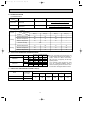
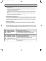
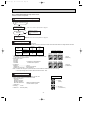
Revision A:
● Conditions of operation frequency have been added.
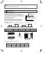
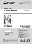
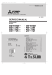
SPLIT-TYPE, HEAT PUMP AIR CONDITIONERS
Please void OB297.
No. OB297
REVISED EDITION-A
SERVICE MANUAL
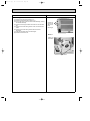
Wireless type
Models
MSZ09UN
MSZ12UN
· MUZ09UN
· MUZ12UN
(W)
(W)
CONTENTS
MSZ09UN
INDOOR UNIT
1. FEATURES ·························································2
2. PART NAMES AND FUNCTIONS······················4
3. SPECIFICATION·················································6
4. DATA···································································8
5. OUTLINES AND DIMENSIONS ·······················18
6. WIRING DIAGRAM ··········································20
Remote
7. REFRIGERANT SYSTEM DIAGRAM ··············22
controller 8. MICROPROCESSOR CONTROL ····················23
9. SERVICE FUNCTIONS ····································39
10. TROUBLESHOOTING······································41
11. DISASSEMBLY INSTRUCTIONS·····················61
12. PARTS LIST······················································68
13. OPTIONAL PARTS···········································74
The Slim Line.
From Mitsubishi Electric.
MUZ09UN
MUZ12UN
OUTDOOR UNIT
TM
C
L IST ED
US
OB297--1.qxp
04.2.4 4:19 PM
Page 2
Revision A:
• Conditions of operation frequency have been added.
• SPECIFICATION, DATA, WIRING DIAGRAM and PARTS LIST have been partially modified.
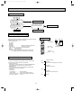
FEATURES
1
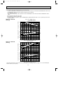
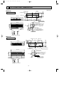
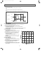
Optimum comfort year-round
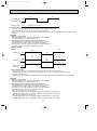
High–speed cooling & heating
Ideal and comforting performance is assured by controlling compressor
rotation according to the cooling and heat load of a room. Inverter technology promotes maximum compressor efficiency by flexibly changing
the rotation speed of it to accurately match operating requirements.
Inverter Model
Constant temperature is maintained
by compressor speed control.
Room Temperature
To ensure that a room is never too cold or too hot, inverter technology
allows the system to detect subtle fluctuations in room temperature and
adjust automatically. Unlike conventional air conditioning units that must start
or stop the compressor repetitively, inverter units offer finely tuned operation
– such as the accurate control of room temperature – for a more comforting
airflow and far less temperature variations.
Single speed comppressor Model
Temperature is adjusted by
turning on/ off the compressor.
Hours
Extra energy – savings
Inverter technology makes the value of SEER and HSPF better compared to non-inverter model’s value.
Cool
Heat
13
7.7
10
6.8
MSH12EN
MSH12EN
MSZ12UN
MSZ12UN
Cooling capacity
Heating capacity
SEER
4/5
5)
HSPF(4
MSZ09UN
8,800 Btu/h
12,300 Btu/h
12.0
7.7/6.7
MSZ12UN
11,400 Btu/h
16,000 Btu/h
13.0
7.7/6.7
Model
MSZ09UN
LCD wireless
remote controller
MUZ09UN
MUZ12UN
MSZ12UN
The sound level of indoor unit has been lowered.
Sound level
(dBA)
Model
Fan speed
High / Low
MSH09EW
MSZ09UN
MSH12EN
MSZ12UN
43 / 32
36 / 22
48 / 38
42 / 35
2
OB297--1.qxp
04.2.4 4:19 PM
Page 3
The height of indoor unit has been shortened.
(in.)
Model
Size
MSH09EW
MSZ09UN
14-13/16
10-15/16
MSH12EN
MSZ12UN
14-3/16
12-5/8
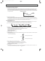
“I FEEL CONTROL” IN OUR LCD WIRELESS REMOTE CONTROLLER WITH ON/OFF PROGRAM TIMER
Mitsubishi Electric’s new wireless remote controller incorporates a number of advanced features that provides even greater
control and ease-to-use. It has a liquid crystal display which indicates such information as mode, fan speed and temperature
selected as well as the programmed ON/OFF timer. It is also equipped with “I Feel Control”, a unique Mitsubishi Electric feature that allows the user to adjust the temperature to exactly the level he or she wants simply by tapping the button that
describes present conditions : “Too Cool” or “Too Warm”. The optimum temperature set this way is that memorized for immediate recall whenever the air conditioner is used again.
Select desired air flow direction.
REMOTE-CONTROL OPERATION MODE
Using the remote controller, you can select from five airflow settings to match room layout and the location of people. Also, you
can set the vane to swing automatically.
SWING
AUTO-RESTART FUNCTION
The auto-restart function restarts the equipment when power is
restored following an outage automatically. Operation resumes in
the mode in which the equipment was running immediately before
the outage.
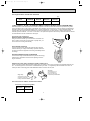
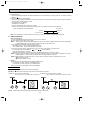
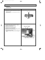
HIGH PERFORMANCE ROTARY COMPRESSOR
The advanced design of Mitsubishi Electric’s powerful and energy
efficient rotary compressor results in lower operating costs and
longer service life.
Outdoor unit: Twin rotary compressor greatly reduces noise
Unlike conventional models equipped with a single rotary, the features a twin-rotary compressor that provides balanced rotation – the centrifugal force of one roller is counterbalanced by the other – for significantly reduced vibration and noise. It’s
exactly this kind of technology that makes Mitsubishi Electric’s outdoor units so quiet.
Twin rotary:
Centrifugal force of one
roller counterbalanced
by that of the other roller
for significantly lower vibration.
Single rotary:
Centrifugal force always
produced in one direction,
resulting in excessive vibration.
The sound level of outdoor unit has been lowered.
Sound level (Cooling/Heating) dB(A)
MUH12EN
MUZ12UN
54 / 54
49 / 49
3
OB297--1.qxp
04.2.4 4:19 PM
2
Page 4
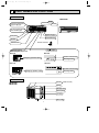
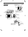
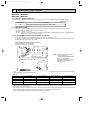
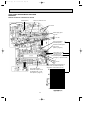
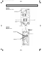
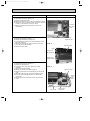
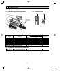
PART NAMES AND FUNCTIONS
INDOOR UNIT
MSZ12UN
MSZ09UN
Grille
Deodorizing filter(option)
(gray sponge type)
Air inlet
Air cleaning filter(option)
(white bellows type)
Remote control
receiving section
Front panel
Horizontal vane
Air filter
Vertical vanes
Remote controller
Operation section
(When the grille is opened)
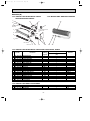
MSZ09UN
MSZ09UN
Operation indicator lamp
Emergency operation switch
Receiving section
MSZ12UN
MSZ12UN
Operation indicator lamp
Emergency operation switch
Receiving section
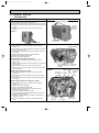
OUTDOOR UNIT
Air inlet
MUZ09UN
MUZ12UN
(back and side)
Piping
Drainage hose
Service panel
Air outlet
Drain outlet
4
OB297--1.qxp
04.2.4 4:19 PM
Page 5
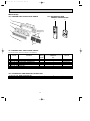
ACCESSORIES
1
2
3
4
5
6
7
MSZ09UN
MSZ12UN
1
5
1
2
2
1
1
1
6
1
2
2
1
1
Installation plate
Installation plate fixing screw 4 x 25 mm(0.16 x 0.98 in.)
Remote controller mounting hardware
Fixing screw for 3 3.5 x 16 mm(0.14 x 0.63 in.) (Black)
Battery (AAA) for remote controller
Wireless remote controller
Felt tape (Used for left or left-rear piping)
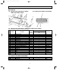
REMOTE CONTROLLER
MSZ09UN
MSZ12UN
Signal transmitting section
Operation display section
OPERATE /STOP
(ON /OFF)button
PM
AM
ON/OFF
TOO
WARM
TOO
COOL
TEMPERATURE buttons
Open the front lid.
CLOCK
PM
AM
TOO
ON/OFF WARM
VANE CONTROL button
TOO
COOL
FAN
STOP
VANE
START
I FEEL COOL
HEAT DRY
MODE
HR.
OPERATION SELECT button
MIN.
RESET CLOCK
RESET button
5
FAN SPEED CONTROL button
OFF-TIMER button
ON-TIMER button
HR. button
MIN. button
(TIME SET button)
CLOCK SET button
OB297--1.qxp
3
04.2.4 4:19 PM
Page 6
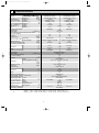
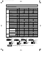
SPECIFICATION
Model
Item
❈1
Capacity
Cooling
Btu/h
Rated(Minimum~Maximum) Heating 47 ❈1
Btu/h
Capacity Rated
Heating 17 ❈2
Btu/h
Power consumption
Cooling ❈1
W
Rated(Minimum~Maximum) Heating 47 ❈1
W
Power consumption Rated Heating 17 ❈2
W
EER ❈1 [SEER] ❈3
Cooling
HSPF IV(V) ❈4
Heating
COP
Heating ❈1
INDOOR UNIT MODEL
External finish
Power supply
V, phase, Hz
Max. fuse size (time delay)/ Disconnect switch
A
Min. circuit ampacity
A
Fan motor
F.L.A
Auxiliary heater
A(kW)
HEAT Dry
CFM
Airflow Low—Med.—High
COOL Dry(Wet)
CFM
Moisture removal
pt./h
Sound level Low-Med.-High
dB(A)
Cond. drain connection O.D.
in.
W
in.
Dimensions
D
in.
H
in.
Weight
Ib.
OUTDOOR UNIT MODEL
External finish
Power supply
V, phase, Hz
Max. fuse size (time delay)
A
Min. circuit ampacity
A
Fan motor
F.L.A
Model
Winding resistance (at 68˚F) Ω
Compressor
R.L.A
L.R.A
Refrigerant control
Sound level
dB(A)
Defrost method
W
in.
Dimensions
D
in.
H
in.
Weight
Ib.
REMOTE CONTROLLER
Control voltage (by built-in transformer)
REFRIGERANT PIPING
Refrigerant pipe size
Liquid
in.
(Min. wall thickness)
Gas
in.
Indoor
Connection method
Outdoor
Between the indoor
Height difference
ft.
& outdoor units
Piping length
ft.
Refrigerant charge (R22)
Refrigerating oil (Model)
oz.
MSZ12UN
11,400(2,900~13,000)
16,000(2,400~19,500)
11,600
1,140(290~1,460)
1,590(280~2,050)
1,760
10.0[13.0]
MSZ09UN
8,800(2,600~9,700)
12,300(2,300~15,700)
10,000
980(290~1,250)
1,320(280~1,770)
1,420
9.0 [12.0]
7.7 (6.7)
2.95
MSZ12UN
2.73
MSZ09UN
White
115, 1, 60
15
0.6
0.43
0.5
0.37
–
360-395-452
360(311)-395(339)-452(388)
2.8
35-39-42
184-237-297
148(124)-215(180)-279(233)
2.3
22-29-36
5/8
39-15/16
33-1/2
7-1/2
10-15/16
20
MUZ09UN
12-5/8
31
MUZ12UN
Munsell 5.6Y 8.0/0.5
208/230, 1, 60
15
14
0.43
SHV-130FEA
U-V 1.05 U-W 1.05 U-W 1.05
9.7
41
Liner expansion valve
49
Reverse cycle
28
10-1/16
21-1/4
75
Wireless type
12V DC
Not supplied (optional parts)
1/4 (0.0265)
1/2 (0.0285)
3/8 (0.0285)
Flared
Flared
Max. 25
Max. 49
2 Ib. 14 oz.
2 Ib. 7 oz.
10.8 (MS56)
NOTE : Test conditions are based on ARI 210/240.
❈1 : Rating conditions (cooling) — Indoor : 80˚FDB, 67˚FWB, Outdoor : 95˚FDB, (75˚FWB) Rated frequency: Hz
(heating) — Indoor : 70˚FDB, 60˚FWB, Outdoor : 47˚FDB, 43˚FWB Rated frequency: Hz
❈2 :
(heating) — Indoor : 70˚FDB, 60˚FWB, Outdoor : 17˚FDB, 15˚FWB Maximum frequency: Hz
6
OB297--1.qxp
04.2.4 4:19 PM
Page 7
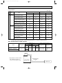
Test condition
(Unit : [˚F])
❈3, ❈4
Mode
ARI
Indoor air condition
Test
Outdoor air condition
Dry bulb
Wet bulb
Dry bulb
Wet bulb
SEER "A" Cooling Steady State
(Cooling) at rated compressor Speed
80
67
95
(75)
"B-2" Cooling Steady State
at rated compressor Speed
80
67
82
(65)
"B-1" Cooling Steady State
at minimum compressor Speed
80
67
82
(65)
Low ambient Cooling Steady State
at minimum compressor Speed
80
67
67
(53.5)
Intermediate Cooling Steady State
At Intermediate compressor Speed❈5
80
67
87
(69)
HSPF Standard Rating-Heating
(Heating) at rated compressor Speed
70
60
47
43
Low temperature Heating
at rated compressor Speed
70
60
17
15
Max temperature Heating
at minimum compressor Speed
70
60
62
56.5
High temperature Heating
at minimum compressor Speed
70
60
47
43
Frost Accumulation
at rated compressor Speed
70
60
35
33
Frost Accumulation
at Intermediate compressor Speed❈5
70
60
35
33
❈5 : At Intermediate compressor Speed
=("Cooling rated compressor speed" - "minimum compressor speed") / 3 + "minimum compressor speed".
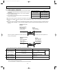
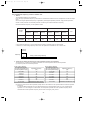
MAX. REFRIGERANT PIPING LENGTH
Piping size : in.
Model
MSZ09UN
MSZ12UN
MUZ09UN
MUZ12UN
Length of connecting pipe : in.
Gas
Liquid
Additional piping
Minimum
Max. length : ft.
Outside Minimum
Outside
Wall
A
diameter thickness diameter Wall
thickness
[ 3/8
49
0.0285
[ 1/4
0.0265
[ 1/2
Indoor unit
Outdoor unit
Gas : 16-15/16
Gas : 0
Liquid : 19-11/16
Liquid : 0
MAX. HEIGHT DIFFERENCE
Indoor
unit
w Height difference should be within
25ft. regardless of which unit,
indoor or outdoor position is high.
Refrigerant Piping
Max.length
A
w Max. Height
difference 25ft.
Outdoor unit
7
OB297--1.qxp
04.2.4 4:19 PM
Page 8
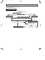
DATA
4
MSZ09UN
MSZ12UN
MUZ09UN
MUZ12UN
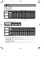
4-1. PERFORMANCE DATA
1) COOLING CAPACITY
Indoor air
Model
IWB
(˚F)
MSZ09UN
MSZ12UN
Outdoor intake air DB temperature(˚F)
75
85
95
105
TC
SHC
TPC
TC
SHC
TPC
TC
SHC
TPC
TC
SHC
71
10.8
6.1
0.87
10.1
5.7
0.96
9.5
5.4
1.03
8.8
5.0
67
10.2
7.1
0.82
9.5
6.7
0.91
8.8
6.2
0.98
8.2
63
9.6
8.0
0.78
8.9
7.4
0.87
8.3
6.9
0.94
71
14.0
8.3
1.01
13.1
7.8
1.11
12.3
7.3
67
13.2
9.7
0.96
12.3
9.0
1.05
11.4
63
12.4
10.7
0.91
11.5
9.9
1.01
10.7
115
TPC
TC
SHC
TPC
1.08
8.1
4.6
1.13
5.7
1.04
7.5
5.3
1.09
7.5
6.3
1.00
6.9
5.7
1.04
1.20
11.4
6.8
1.26
10.5
6.3
1.31
8.3
1.14
10.6
7.7
1.21
9.7
7.1
1.27
9.3
1.09
9.7
8.4
1.16
8.9
7.7
1.21
NOTE 1. IWB : Intake air wet-bulb temperature
TC : Total Capacity (x103 Btu/h), SHC : Sensible Heat Capacity (x103 Btu/h)
TPC : Total Power Consumption (kW)
2. SHC is based on 80˚F of indoor intake air DB temperature.
2) COOLING CAPACITY CORRECTIONS
Refrigerant piping length (one way : ft.)
Model
MSZ09UN
MSZ12UN
MUZ09UN
MUZ12UN
25 (std.)
40
49
1.0
0.954
0.927
3) HEATING CAPACITY
Indoor air
Model
MSZ09UN
MSZ12UN
IDB
(˚F)
Outdoor intake air WB temperature(˚F)
15
25
35
43
45
55
TC
TPC
TC
TPC
TC
TPC
TC
TPC
TC
TPC
TC
TPC
75
7.1
0.98
8.9
1.16
10.6
1.29
12.0
1.35
12.4
1.37
14.0
1.43
70
7.6
0.95
9.2
1.13
10.9
1.25
12.3
1.32
12.7
1.35
14.3
1.40
65
7.7
0.91
9.7
1.09
11.3
1.22
12.7
1.29
13.0
1.31
14.6
1.37
75
9.3
1.18
11.6
1.39
13.8
1.55
15.6
1.63
16.1
1.65
18.2
1.72
70
9.8
1.14
12.0
1.36
14.2
1.51
16.0
1.59
16.5
1.62
18.6
1.69
65
10.1
1.10
12.6
1.31
14.6
1.47
16.5
1.55
17.0
1.57
19.0
1.65
NOTE: 1. IDB : Intake air dry-bulb temperature
TC : Total Capacity (x103 Btu/h)
TPC : Total Power Consumption (kW)
2. Above data is for heating operation without any frost.
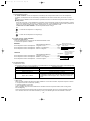
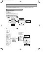
How to operate with fixed operational frequency of the compressor.
1. Press the EMERGENCY OPERATION switch on the front of the indoor unit, and select either EMERGENCY COOL mode
or EMERGENCY HEAT mode before starting to operate the air conditioner.
2. The compressor starts up.
The operational frequency of the compressor is MSZ09UN: 64Hz, MSZ12UN: 70Hz in EMERGENCY COOL mode and
58Hz in EMERGENCY HEAT mode.
3. The fan speed of the indoor unit is High.
4. This operation continues for 30minutes.
5. In order to release this operation, press the EMERGENCY OPERATION switch twice or once, or press any button on the
remote controller.
8
OB297--1.qxp
04.2.4 4:19 PM
Page 9
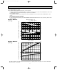
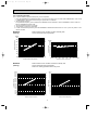
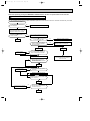
4-2. PERFORMANCE CURVE
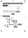
How to operate with fixed operational frequency of the compressor.
1. Press the EMERGENCY OPERATION switch on the front of the indoor unit, and select either EMERGENCY COOL mode
or EMERGENCY HEAT mode before starting to operate the air conditioner.
2. The compressor starts up.
The operational frequency of the compressor is 64Hz in EMERGENCY COOL mode and 58Hz in EMERGENCY HEAT
mode.
3. The fan speed of the indoor unit is High.
4. This operation continues for 30minutes.
5. In order to release this operation, press the EMERGENCY OPERATION switch twice or once, or press any button on the
remote controller.
SHF at rating condition = 0.70
Airflow = 233CFM
Bypass Factor = 0.23
Total power consumption (kW)
Total capacity ( ✕103 Btu/h)
MSZ09UN MUZ09UN
(Cooling)
12
Indoo
r intak
e air W
B tem
10
peratu
re (°F
)
8
71
67
63
6
1.2
F)
rature (°
71
67
63
B tempe
e air W
oor intak
1.0
Ind
0.8
0.6
0.4
65
75
85
95
105
115
Outdoor intake air DB temperature (°F)
Total capacity ( ✕103 Btu/h)
Airflow = 297CFM
Total power consumption (kW)
MSZ09UN MUZ09UN
(Heating)
15
ture
oor
a
ake
)
(°F
a
per
em
Bt
ir D
13
65
70
75
int
Ind
11
9
7
1.6
1.4
75
70
65
ture (°F)
B tempera
ke air D
door inta
In
1.2
1.0
0.8
0.6
15
25
35
45
55
Outdoor intake air WB temperature (°F)
This value of frequency is not the same as the actual frequency in operating. Refer to the page 16, 17 for the relationships
between frequency and capacity.
9
OB297--1.qxp
04.2.4 4:19 PM
Page 10
How to operate with fixed operational frequency of the compressor.
1. Press the EMERGENCY OPERATION switch on the front of the indoor unit, and select either EMERGENCY COOL mode
or EMERGENCY HEAT mode before starting to operate the air conditioner.
2. The compressor starts up.
The operational frequency of the compressor is 70Hz in EMERGENCY COOL mode and 58Hz in EMERGENCY HEAT
mode.
3. The fan speed of the indoor unit is High.
4. This operation continues for 30minutes.
5. In order to release this operation, press the EMERGENCY OPERATION switch twice or once, or press any button on the
remote controller.
SHF at rating condition = 0.73
Airflow = 388CFM
Bypass Factor = 0.19
Total power consumption (kW)
Total capacity ( ✕10 Btu/h)
MSZ12UN MUZ12UN
(Cooling)
Indo
or in
14
take
air W
B te
mpe
12
ratu
re (°
F)
71
10
67
63
8
1.5
1.3
1.1
Indoor
ir WB
intake a
)
ture (°F
tempera
71
67
63
0.9
0.7
0.5
65
75
85
95
105
115
Outdoor intake air DB temperature (°F)
MSZ12UN MUZ12UN
(Heating)
Airflow = 452CFM
Total power consumption (kW)
Total capacity ( ✕10 Btu/h)
21
ure
17
rat
mpe
65
70
75
(°F)
B te
ake
r int
air D
o
13
Indo
9
2.0
1.8
)
rature (°F
B tempe
ke air D
door inta
In
1.6
75
70
65
1.4
1.2
1.0
15
25
35
45
55
Outdoor intake air WB temperature (°F)
This value of frequency is not the same as the actual frequency in operating. Refer to the page 16, 17 for the relationships
between frequency and capacity.
10
OB297--1.qxp
04.2.4 4:19 PM
Page 11
4-3. Condensing pressure
How to operate with fixed operational frequency of the compressor.
1. Press the EMERGENCY OPERATION switch on the front of the indoor unit, and select either EMERGENCY COOL mode
or EMERGENCY HEAT mode before starting to operate the air conditioner.
2. The compressor starts up.
The operational frequency of the compressor is MSZ09UN: 64Hz, MSZ12UN: 70Hz in EMERGENCY COOL mode and
58Hz in EMERGENCY HEAT mode.
3. The fan speed of the indoor unit is High.
4. This operation continues for 30minutes.
5. In order to release this operation, press the EMERGENCY OPERATION switch twice or once, or press any button on the
remote controller.
MSZ09UN
(Cooling)
Data is based on the condition of indoor humidity 50%.
Air flow should be set to High speed.
(PSIG)
300
86
80
75
70
260
(PSIG)
100
95
90
85
80
75
70
65
60
55
50
45
40
68 70
°F)
e(
240
ur
rat
pe
em
Bt
220
rD
oo
Ind
200
180
160
140
68 70
75
80
85
90
95
100 104(°F)
Outdoor ambient temperature
MSZ09UN
(Heating)
86
80
75
70
75
80
85
90
95
Outdoor ambient temperature
70
65
)
°F
re(
tu
era
B
rD
oo
Ind
(PSIG)
100
95
90
85
80
75
70
65
60
55
50
45
40
35
30
25
20
15
10
5
100 104(°F)
75
70
65
Suction pressure
Condensing pressure
75
5
Indoor DB tempe
Data is based on the condition of outdoor humidity 75%.
Air flow should be set to High speed.
Data is for heating operation without any frost.
(PSIG)
310
300
290
280
270
260
250
240
230
220
210
200
190
180
170
160
150
rature (°F)
Suction pressure
Condensing pressure
280
p
tem
10 15 20 25 30 35 40 45 50 55 60 65 70(°F)
ure
)
(°F
t
era
p
B
rD
tem
oo
Ind
10
15
20
25
30
35
40
45
50
Outdoor ambient temperature
Outdoor ambient temperature
11
55
60
65 70(°F)
OB297--1.qxp
04.2.4 4:19 PM
Page 12
MSZ12UN
(Cooling)
Data is based on the condition of indoor humidity 50%.
Air flow should be set to High speed.
(PSIG)
300
86
80
75
70
260
(PSIG)
110
105
100
95
90
85
80
75
70
65
60
55
50
68 70
)
(°F
e
tur
ra
pe
240
or
o
Ind
220
DB
tem
200
180
160
140
68 70
75
80
85
90
95
100 104(°F)
Outdoor ambient temperature
(PSIG)
100
95
90
85
80
75
70
65
60
55
50
45
40
35
30
25
20
15
10
5
80
75
70
75
80
85
90
95
Outdoor ambient temperature
100 104(°F)
75
)
(°F
re
atu
r
pe
B
rD
oo
Ind
70
65
75
70
65
Suction pressure
Condensing pressure
(PSIG)
5
86
Data is based on the condition of outdoor humidity 75%.
Air flow should be set to High speed.
Data is for heating operation without any frost.
MSZ12UN
(Heating)
280
270
260
250
240
230
220
210
200
190
180
170
160
150
140
130
120
rature (°F)
Indoor DB tempe
Suction pressure
Condensing pressure
280
tem
10 15 20 25 30 35 40 45 50 55 60 65 70(°F)
ure
)
(°F
t
era
p
B
rD
tem
oo
Ind
10
15
20
25
30
35
40
45
50
Outdoor ambient temperature
Outdoor ambient temperature
12
55
60
65 70(°F)
OB297--1.qxp
04.2.4 4:20 PM
Page 13
4-4. STANDARD OPERATION DATA
Model
Item
Cooling
Heating
Cooling
Heating
Btu / h
8,800
12,300
11,400
16,000
SHF
—
0.70
–
0.73
–
Input
kW
980
1,320
1,140
1,590
Rated frequency
Hz
64
76
70
Unit
Capacity
Total
99
Indoor unit
MSZ09UN
MSZ12UN
Power supply (V, phase, Hz)
115, 1, 60
115, 1, 60
kW
0.035
0.047
Fan motor current
A
0.34
0.41
Aux. heater current
A
–
–
Input
Electrical
circuit
MSZ12UN
MSZ09UN
MUZ09UN
MUZ12UN
208/230, 1, 60
208/230, 1, 60
Outdoor unit
Power supply (V, phase, Hz)
kW
0.945
Comp. current
A
5.34/5.11
Fan motor current
A
Input
1.285
1.093
6.84/6.81
5.84/5.71
1.543
8.24/7.71
0.36/0.39
0.36/0.39
276
265
256
Condensing pressure
PSIG
Suction pressure
PSIG
74
59
87
57
˚F
184
198
186
197
˚F
112
122
Discharge temperature
Refrigerant
Condensing temperature
circuit
237
118
Suction temperature
˚F
52
36
54
34
Comp. shell bottom temp
˚F
154
172
160
171
Ref. pipe length
ft.
2 Ib. 14 oz.
2 Ib. 7 oz.
—
Refrigerant charge (R22)
25
25
DB
˚F
80
70
80
70
WB
˚F
67
60
67
60
DB
˚F
57
100
58
114
WB
˚F
56
–
56
–
rpm
950
1,000
Intake air temperature
Indoor
unit
Discharge air temperature
Fan speed (High)
CFM
233(Wet)
297(Dry)
388(Wet)
452(Dry)
DB
˚F
95
47
95
47
WB
˚F
–
43
–
43
Airflow (High)
Outdoor
unit
1,200
Intake air temperature
Fan speed
rpm
650/720
650/720
Airflow
CFM
847/953
847/953
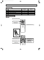
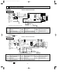
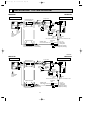
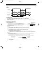
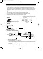
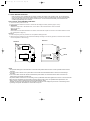
POWER SUPPLY
MSZ09UN
INDOOR UNIT
115V
1phase 60Hz,
2 wires
MSZ12UN
SIGNAL WIRE
2 wires 12V DC
208/230V
1phase 60Hz,
2 wires
OUTDOOR UNIT
✻ Control voltage
INDOOR UNIT
INDOOR UNIT
Disconnect
switch
115V
1phase 60Hz,
2wires
115V
1phase 60Hz,
2 wires
SIGNAL WIRE
2 wires 12V DC
115V
208/230V
1phase 60Hz,
OUTDOOR UNIT
3 wires
INDOOR UNIT
SIGNAL WIRE
2 wires 12V DC
Disconnect
switch
208/230V
1phase 60Hz,
2 wires
208/230V
1phase 60Hz,
3 wires
OUTDOOR UNIT
OUTDOOR UNIT
Power supply voltage to serial signal circuit is 12V DC.
Voltage between 1 - and 3 + on in-out terminal block will be 12V DC peak voltage.
13
SIGNAL WIRE
2 wires 12V DC
115V
1phase 60Hz,
2 wires
115V
OB297--1.qxp
04.2.4 4:20 PM
Page 14
4-5. OPERATING RANGE
(1) POWER SUPPLY
Rated voltage
Model
Guaranteed Voltage
Min. 103V
Indoor unit
MSZ09UN
MSZ12UN
115V 1phase 60Hz
Outdoor unit
MUZ09UN
MUZ12UN
208/230V 1phase 60Hz
115V Max. 127V
Min. 198V 208V 230V Max. 253V
(2) OPERATION
Intake air
temperature
Function
Outdoor
Indoor
DB (˚F)
WB (˚F)
DB (˚F)
WB (˚F)
Standard temperature
80
67
95
—
Maximum temperature
95
71
115
—
Minimum temperature
67
57
67
—
Condition
Cooling
78%
Maximum humidity
Heating
—
Standard temperature
70
60
47
43
Maximum temperature
80
67
75
65
Minimum temperature
70
60
17
15
4-6. OUTLET AIR SPEED AND COVERAGE RANGE
Model
MSZ09UN
Mode
Function
HEAT
Dry
Dry
Wet
Dry
Dry
Wet
COOL
HEAT
MSZ12UN
COOL
Air flow Air speed Coverage ● The air coverage range is the figure up
(CFM) (ft./sec.) range (ft.)
to the position where the air speed is 1
22.3
15.8
297
ft./sec., when air is blown out horizon21.0
14.9
279
tally from the unit properly at the High
17.6
12.4
233
speed position.
29.2
18.2
452
The coverage range should be used
29.2
18.2
452
only as a general guideline since it
25.2
15.6
388
varies according to the size of the room
and furniture arranged inside the room.
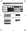
4-7. ADDITIONAL REFRIGERANT CHARGE R22(oz.)
Model
Outdoor unit
precharged
(up to 25ft.)
MSZ09UN
MUZ09UN
2 lb. 7 oz.
MSZ12UN
MUZ12UN
2 lb. 14 oz.
Refrigerant piping length (one way)
25ft.
30ft.
35ft.
40ft.
45ft.
49ft.
0
1.62
3.24
4.86
6.48
8.10
14
OB297--1.qxp
04.2.4 4:20 PM
MSZ09UN
MUZ09UN
Page 15
MSZ12UN
MUZ12UN
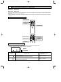
The standard data contained in these specifications apply only to the operation of the system under normal conditions. Since
operating conditions vary according to the areas where these units are installed. The following information has been provided
to clarify the operating characteristics of the system under the conditions indicated by the performance curve.
(1) GUARANTEED VOLTAGE
INDOOR UNIT
OUTDOOR UNIT
103 ~ 127V 60Hz
198 ~ 253V 60Hz
(2) AIR FLOW
Air flow should be set at MAX.
(3) MAIN READINGS
(1) Indoor intake air wet-bulb temperature
(2) Indoor outlet air wet-bulb temperature
(3) Outdoor intake air dry-bulb temperature
(4) Total input
(5) Indoor intake air dry-bulb temperature
(6) Outdoor intake air wet-bulb temperature
(7) Total input
:°F
:°F
:°F
:W
:°F
:°F
:W
WB
WB
DB
DB
WB
}
}
Cooling
Heating
Indoor air wet/dry-bulb temperature difference on the left side of the chart on page 16 and 17 shows the difference
between the indoor intake air wet/dry-bulb temperature and the indoor outlet air wet/dry-bulb temperature for your reference at service.
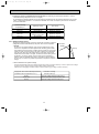
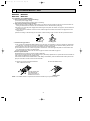
How to measure the indoor air wet-bulb/ dry-bulb temperature difference
1.
2.
3.
4.
5.
6.
7.
Attach at least 2 sets of wet-and dry-bulb thermometers to the indoor air intake as shown in the figure, and at least 2 sets
of wet-and dry-bulb thermometers to the indoor air outlet. The thermometers must be attached to the position where air
speed is high.
Attach at least 2 sets of wet-and dry-bulb thermometers to the outdoor air intake.
Cover the thermometers to prevent direct rays of the sun.
Check that the air filter is cleaned.
Open windows and doors of room.
Press the EMERGENCY OPERATION switch once (twice) to start the EMERGENCY COOL (HEAT) MODE.
When system stabilizes after more than 15 minutes, measure temperature and take an average temperature.
10 minutes later, measure temperature again and check that the temperature does not change.
OUTDOOR UNIT
INDOOR UNIT
15
OB297--1.qxp
04.2.4 4:20 PM
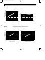
Page 16
Cooling capacity
✴ These values are under rated (frequency).
18.7
13.9
17.1
12.8
15.5
11.7
14.0
10.6
12.6
9.5
11.2
8.5
79
79
75
75
72
68
64
72
68
MSZ12UN
MSZ09UN
64
80
85
90
95
100
105
110
80
85
Correction of Cooling capacity
100
105
110
Correction of total input
1.5
1.5
Input correction factors
Capacity correction factors
95
MUZ09UN
MUZ09UN
1.0
0.5
0.0
0
50
100
1.0
0.5
0.0
0
150(Hz)
The operational frequency of compressor
100
150(Hz)
MUZ12UN
Correction of Cooling capacity
Correction of total input
1.5
Input correction factors
1.5
1.0
0.5
0.0
0
50
The operational frequency of compressor
MUZ12UN
Capacity correction factors
90
50
100
150(Hz)
The operational frequency of compressor
1.0
0.5
0.0
0
50
100
150(Hz)
The operational frequency of compressor
16
OB297--1.qxp
04.2.4 4:20 PM
Page 17
Heating capacity
NOTE:The following curves are for the heating operation without any frost.
✴ These values are under rated (frequency).
43.2
1.4
46.6
39.8
1.3
42.7
36.5
1.2
38.9
33.1
1.1
34.9
30.0
1.0
31.0
26.5
0.9
27.2
23.2
0.8
23.2
20.0
0.7
MSZ12UN
0.6
14
59
68
79
79
68
59
30
20
40
60
50
14
Correction of Heating capacity
30
40
50
60
Correction of total input
1.5
Input correction factors
1.5
Capacity correction factors
20
MUZ09UN
MUZ09UN
1.0
0.5
0.0
0
50
100
1.0
0.5
0.0
0
150(Hz)
The operational frequency of compressor
100
150(Hz)
MUZ12UN
Correction of Heating capacity
Correction of total input
1.5
Input correction factors
1.5
1.0
0.5
0.0
0
50
The operational frequency of compressor
MUZ12UN
Capacity correction factors
MSZ09UN
50.4
50
100
150(Hz)
The operational frequency of compressor
1.0
0.5
0.0
0
50
100
150(Hz)
The operational frequency of compressor
17
OB297--1.qxp
04.2.4 4:20 PM
5
Page 18
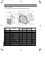
OUTLINES AND DIMENSIONS
Unit: inch
3-1/4
3/16
INDOOR UNIT
6-5/8
9-1/8
Installation plate
Indoor unit
10-11/16
MSZ09UN
3-1/4
12-13/16
33-1/2
3/4
2-5/8
Air out
3-1/16
Liquid line [1/4 19-11/16
Gas line [3/8 16-15/16
Insulation [1-7/16 O.D
[13/16 I.D
Drain hose [5/8
(Connected part O.D)
Insulation [1-1/8
6-3/8
2-5/16
{
6-1/2
3-15/16
24-3/4
4-5/8
Wall hole [2-9/16
3/16
Installation plate
1/4 or more
10-15/16
7-7/16
Air in
2-1/4
12-13/16
1-5/8
1/8
1-5/8
32-3/16
Wireless remote controller
MSZ12UN
8-9/16
17-11/16
17-11/16
17-1/4
13-7/8
Wall hole [2-15/16
Installation plate
39-15/16
12-5/8
7-1/2
1-15/16
30-1/2
Air out
3/4
6-3/8
2-5/16
7-1/2
Wireless remote controller
18
3/16
Installation plate
{
Air in
13/16
25-1/2
11-11/16
5-7/8
1/8
39-3/16
Indoor unit
10-13/16
2-3/8
1-9/16
4holes 7/16 O 13/16
10
INDOOR UNIT
Liquid line [ 5/16 19-11/16
Gas line [1/2 16-15/16
Insulation [ 1-15/16 O.D
[ 1-1/8 I.D
Drain hose [ 5/8
Insulation [ 1-1/8
04.2.4 4:20 PM
Page 19
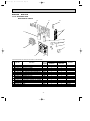
MUZ09UN MUZ12UN
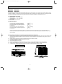
OUTDOOR UNIT
Even if the right/left sides
or back side are vacant, the
top has to be at least 4 in.
unobstructed.
4 in
. or
Drainage holes [1-3/32
1-9/32
1-9/16
Air out
. or
4 in
e
mor
re
ly
ical ted
Bas bstruc
uno
14
in.
o
rm
Even if the right/left sides or back side
ore
are vacant, the front has to be at least
4 in. unobstructed.
WA In case of poorly-ventilated place, the front or the back
has to be at least 8 in. unobstructed.
WB The wall may get dirty in case the air is discharged
toward it.
12-5/8
5
Air in
Drainage holes [1-3/32
1-5/16
11-7/32
Drainage holes [1-3/32
Drainage holes [1-3/32
10-1/32
1-3/8
1-9/32
3-5/8
10-7/16
WA
mo
WA
WB
19-1/2
14-7/16
Air in
4 holes 3/8o13/16
Unit: inch
REQUIRED SPACE
Basically
unobstructed
OB297--1.qxp
Service panel
25/32
11/16
Liquid refrigerant pipe joint
Handle
3543 4-1/8
10-7/16
3-17/32
6-3/32
3/8
10-5/8
21-1/4
Refrigerant pipe (flared) [1/4
Gas refrigerant pipe joint
2-11/16
5-7/16
19-11/16
Bolt pitch for installation
28
Service port
Refrigerant pipe (flared)
[3/8 (MUZ09UN)
[1/2 (MUZ12UN)
T.B. cover
Lock nut
Conduit cover
Connector
Service panel
Remove the screw
holding the T.B.
cover, and then
remove the cover
19
Remove one fixing
screw to open the
service panel
OB297--1.qxp
04.2.4 4:20 PM
6
Page 20
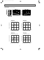
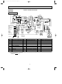
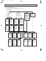
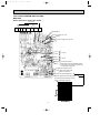
WIRING DIAGRAM
MSZ09UN
INDOOR UNIT
(
TO OUTDOOR
UNIT
CONNECTING
WIRES
12V DC
FROM OUTDOOR
UNIT
CONNECTING
WIRES
POWER
SUPPLY
115V
1 phase
60Hz
TO OUTDOOR
UNIT
CONNECTING
WIRE
MODEL WIRING DIAGRAM
TB ORN
3+
)
N
BLK
L1
RED
5
POWER MONITOR,
RECEIVER
P.C.BOARD
REMOTE
CONTROLLER
NAME
SYMBOL
VANE MOTOR
C11
INDOOR FAN CAPACITOR
F11
FUSE(3A)
NR11
VARISTOR
DC/DC CONVERTER
RT11
ROOM TEMPERATURE THERMISTOR
RT12
MAIN INDOOR COIL THERMISTOR
MV
INDOOR FAN MOTOR(INNER FUSE)
MF
RT11
C11
SR141
3
ELECTRONIC CONTROL P.C. BOARD
w A disconnect may be required by local code.
HIC1
CN211
CN
111
TRANS
LD101T
5
NAME
1
2
3
RT12
BLK 1
GRY 2
YLW 3
BRN 4 MF
WHT
5
RED 6
CN112
CN
121
NR11
F11
CN
151
RT13
1
TAB12
MV
SYMBOL
4
3
2
HIC1
1
2
3
4
VLT
1-
w
CN201
SYMBOL
NAME
RT13
SUB INDOOR COIL THERMISTOR
SR141
SOLID STATE RELAY
TERMINAL BLOCK
TB
NOTE:1. About the outdoor side electric wiring, refer to the outdoor unit electric wiring diagram for servicing.
2. Use copper conductors only.(For field wiring)
3. Symbols below indicate;
: Terminal block,
: Connector
MODEL WIRING DIAGRAM
TB
3+ ORN
w
1-
VLT
N
BLK
CN201
1
2
3
4
L1
RED
TAB12
HIC1
F11
)
TRANS
RED
CN
102
DSAR
(
TO OUTDOOR
UNIT
CONNECTING
WIRES
12V DC
FROM OUTDOOR
UNIT
CONNECTING
WIRES
POWER
SUPPLY
115V
1 phase
60Hz
TO OUTDOOR
UNIT
CONNECTING
WIRE
NR11
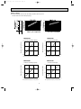
MSZ12UN
INDOOR UNIT
CN
151
3
CN
104
5
CN
101
CN
112
RT12
CN
111
RT11
WHT
ORN
RED
BLK
YLW
BLU
BRN
LDCOM
LDC11
C11
LDC12
SR144 LDFH
SR142 LDFL
SR143 LDFM
SR141 LDFVL
ELECTRONIC CONTROL P.C. BOARD
5
1
2
3
4
5
6
7
8
WHT
ORN
RED
BLK
YLW
BLU
BRN
MF
GRN/YLW
3
GRN/YLW
DISPLAY
P.C.BOARD
MV
AUTO RESTART
ASSY
RECEIVER
P.C.BOARD
w A disconnect may be required by local code.
NAME
SYMBOL
C11
DSAR
F11
HIC1
REMOTE
CONTROLLER
SYMBOL
NAME
SYMBOL
NAME
INDOOR FAN CAPACITOR
MF
INDOOR FAN MOTOR(INNER FUSE)
RT12
INDOOR COIL THERMISTOR
SURGE ABSORVER
MV
VANE MOTOR
FUSE(3A)
NR11
VARISTOR
DC/DC CONVERTER
RT11
ROOM TEMPERATURE THERMISTOR
NOTE:1. About the outdoor side electric wiring, refer to the outdoor unit electric wiring diagram for servicing.
2. Use copper conductors only. (For field wiring)
3. Symbols below indicate;
/: Terminal block,
: Connector
20
SR141~SR144 SOLID STATE RELAY
TB
TERMINAL BLOCK
OB297--1.qxp
04.2.4 4:20 PM
Page 21
MUZ09UN
MUZ12UN
MODELS WIRING DIAGRAM
OUTDOOR UNIT
LDE2
BLK
L1
RED
CN721 1 2
CN771 6 5 4 3 2 1
TB1
N
RED
BLK
L2
BLU
FROM INDOOR UNIT
RED
L1
RELAY
P.C. BOARD C65
21S4
NAME
CURRENT TRANSFORMER
C61
POWER-FACTOR CAPACITOR L61
C63
SMOOTHING CAPACITOR
C65
OUTDOOR FAN CAPACITOR MC
CY61~64 CAPACITOR
DSA61
SURGE ABSORBER
DS61,62 DIODE STACK
LEV
TABW
CN641
1 2 3 4
N
IPM
1 2 3
BLK
RED
WHT V
BLK
RT64
RT61 RT62
W
SYMBOL
CT61
TABV
V
W
CN601
3 2 1
MF61
TABU
U
ELECTRONIC
CONTROL
P.C. BOARD
R.V. coil
heating ON
cooling OFF
GROUND
SYMBOL
3
P
ORN
N
TAB
67
VLT
TO INDOOR UNIT
CONNECTING
115V
1 phase 60Hz
LEV
R61
1 2 CN724
CN642
F901 LD62
X61
VLT
T801
TAB
N
6
WHT
1
POWER
SUPPLY
208/230V
1 phase 60Hz
4
BLK
3
TAB
P
YLW
–
ORN
LD64
FROM INDOOR UNIT
CONNECTING WIRES
12V DC
C63
YLW
–
TAB68
SSR61
TB2
ORN
YLW
+
CN722 CN726
LDE1
GRN
RED
C61
BLU
TAB65
RED
F801
WHT
R64
4
TAB66
WHT
NOISE FILTER
P.C. BOARD
BLK
+
CT61
(~) (+)
BLK (–) (~)
L61
TAB69
3
L63
BLU
DS62
RED
DS61
(~) (+)
(–) (~)
CN725
X64
L62
CY64 CY63
CY62 CY61
RED
CN723
NR61
GRN
BLK
WHT
RED
DSA61
NAME
SYMBOL
MC
U
NAME
EXPANSION VALVE COIL
R64
CURRENT-LIMITING RESISTOR
REACTOR
SSR61
SOLID STATE RELAY
L62,L63 COMMON MODE CHOKE COIL TB1,2
COMPRESSOR
T801
TERMINAL BLOCK
TRANSFORMER
MF61
OUTDOOR FAN MOTOR(INNER PROTECTOR) X61
NR61
VARISTOR
X64
RELAY
RT61
DEFROST THERMISTOR
21S4
R.V. COIL
F801
FUSE (2A)
RT62
DISCHARGE TEMPERATURE THERMISTOR
F901
FUSE (1A)
RT64
FIN TEMPERATURE THERMISTOR
IPM
INTELLIGENT POWER MODULE R61
CURRENT-DETECTING RESISTOR
NOTE:1. About the indoor side electric wiring refer to the indoor unit electric wiring diagram for servicing.
2.Use copper conductors only. (For field wiring)
3. Symbols below indicate.
/: Terminal block,
: Connector
21
FAN MOTOR RELAY
OB297--1.qxp
7
04.2.4 4:20 PM
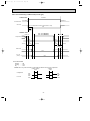
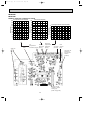
Page 22
REFRIGERANT SYSTEM DIAGRAM
Unit:inch
MUZ09UN
MSZ09UN
OUTDOOR UNIT
INDOOR UNIT
Refrigerant pipe {3/8
(with heat insulator)
Indoor
heat
exchanger
Main
indoor coil
thermistor
RT12
Flared connection
4-way valve
Muffler
Stop valve
(with service port)
Fusible
plug
Service
port
Discharge
temperature
thermistor
RT62
Service
port
Sub
indoor coil
thermistor
Room
RT13
Temperature
thermistor
RT11
Muffler
Compressor
Defrost
thermistor
RT61
Capillary
tube
O.D.0.12OI.D.0.079O11-13/16
Flared connection
Refrigerant pipe {1/4
(with heat insulator)
Outdoor
heat
exchanger
Expansion
valve
Capillary tube
O.D.0.12OI.D.0.079O7-7/8
Strainer
Stop valve
(with strainer)
Capillary
tube
O.D.0.12OI.D.0.079O11-13/16
R.V. coil
heating ON
cooling OFF
Flow of refrigerant (cooling)
Flow of refrigerant (heating)
Unit:inch
MUZ12UN
MSZ12UN
INDOOR UNIT
OUTDOOR UNIT
Refrigerant pipe {1/2
(with heat insulator)
Indoor
heat
exchanger
Main
indoor coil
thermistor
RT12
Flared connection
4-way valve
Muffler
Stop valve
(with service port)
Fusible
plug
Service
port
Room
Temperature
thermistor
RT11
Service
port
Discharge
temperature
thermistor
RT62
Muffler
Compressor
Defrost
thermistor
RT61
Capillary
tube
O.D.0.12OI.D.0.079O11-13/16
Flared connection
Refrigerant pipe {1/4
(with heat insulator)
Expansion
valve
Capillary tube
O.D.0.12OI.D.0.079O7-7/8
Strainer
Stop valve
(with strainer)
22
Outdoor
heat
exchanger
Capillary
tube
O.D.0.12OI.D.0.079O11-13/16
R.V. coil
heating ON
cooling OFF
Flow of refrigerant (cooling)
Flow of refrigerant (heating)
OB297--1.qxp
04.2.4 4:20 PM
8
Page 23
MICROPROCESSOR CONTROL
MSZ09UN
MSZ12UN
MUZ09UN
MUZ12UN
Once the operation mode are set, the same operation mode can be repeated by simply turning the OPERATE/STOP(ON/OFF)
button ON.
Indoor unit receives the signal with a beep tone.
When the system turns off, 3-minute time delay will operate to protect system from overload and compressor will not restart for
3 minutes.
WIRELESS REMOTE CONTROLLER
Signal transmitting section
Operation display section
PM
AM
OPERATE /STOP
(ON /OFF)button
TOO
ON/OFF WARM
TOO
COOL
TEMPERATURE buttons
TOO
ON/OFF WARM
VANE CONTROL button
TOO
COOL
FAN
STOP
VANE
START
I FEEL COOL
FAN SPEED CONTROL button
OFF-TIMER button
HEAT DRY
ON-TIMER button
MODE
HR.
OPERATION SELECT button
MIN.
HR. button
MIN. button
(TIME SET button)
RESET CLOCK
CLOCK SET button
RESET button
INDOOR UNIT DISPLAY SECTION
Operation Indicator lamp
The operation indicator located at the right side of the indoor unit indicates the operation state.
• The following indication applies regardless of shape of the indicatior.
Operation Indicator
lighted
not lighted
Indication
Operation state
Difference between target
temperature and room
temperature
This shows that the air conditioner is operating to reach
the target temperature.
Please wait until the target temperature is obtained.
Approx. 4 ˚F or more
This shows that the room temperature is
approaching the target temperature.
Approx. 4 ˚F or less
23
OB297--1.qxp
04.2.4 4:20 PM
Page 24
8-1. “I FEEL CONTROL” OPERATION
(1) Press OPERATE/STOP(ON/OFF) button on the remote controller.
OPERATION INDICATOR lamp of the indoor unit turns on with a
beep tone.
(2) Press OPERATION SELECT button to set “I FEEL CONTROL”.
Then a beep tone is heard.
(3) The operation mode is determined by the room temperature at
start-up of the operation.
Initial room temperature
77˚F or more
73˚F to 77˚F
less than 73˚F
mode
COOL mode of
“I FEEL CONTROL”
DRY mode of
“I FEEL CONTROL”
HEAT mode of
“I FEEL CONTROL”
● Once the mode is fixed, the mode does not change by room temperature afterwards.
● Under the ON-TIMER ( START) operation, mode is determined according to the room temperature as the operation
starts.
● When the system is stopped with the OPERATE/STOP(ON/OFF) button on the remote controller, and restarted within 2
hours in “I FEEL CONTROL” mode, the system operates in previous mode automatically regardless of the room temperature.
Operation time chart
Example
Previous operation
COOL mode of
“I FEEL CONTROL”
or COOL mode
Restart
COOL mode of
“I FEEL CONTROL”
When the system is restarted after 2 hours and more, the operation mode is determined by the room temperature at
start-up of the operation.
Operation time chart
Example
Previous operation
COOL mode of
“I FEEL CONTROL” or
COOL mode
Restart
COOL or DRY or HEAT
mode of “I FEEL CONTROL” that determined
by room temperature at
start-up of the operation.
(4) The initial set temperature is decided by the initial room temperature.
Mode
COOL mode of
“I FEEL CONTROL”
DRY mode of
“I FEEL CONTROL”
HEAT mode of
“I FEEL CONTROL”
Initial room temperature
Initial set temperature
75˚F
79˚F or more
Initial room temperature
minus 4˚F
Initial room temperature
minus 4˚F
77˚F to 79˚F
73˚F to 77˚F
less than 73˚F
❈1
79˚F
❈1 When the system is restarted with the remote controller, the system operates with the previous set temperature regardless of the room temperature at restart.
The set temperature is calculated by the previous set temperature.
24
OB297--1.qxp
04.2.4 4:20 PM
Page 25
(5) TEMPERATURE buttons
In “I FEEL CONTROL” mode, set temperature is decided by the microprocessor based on the room temperature.
In addition, set temperature can be controlled by TOO WARM or TOO COOL buttons when you feel too cool or too
warm.
Each time the TOO WARM or TOO COOL button is pressed, the indoor unit receives the signal and emits a beep tone.
● Fuzzy control
When the TOO COOL or TOO WARM button is pressed, the microprocessor changes the set temperature, considering the room temperature, the frequency of pressing TOO COOL or TOO WARM button and the user’s preference to
heat or cool. So this is called “Fuzzy control”, and works only in “I FEEL CONTROL” mode.
In DRY mode of “I FEEL CONTROL”, the set temperature doesn’t change.
TOO
COOL
… To raise the set temperature 2~4 degrees(°F)
TOO
WARM
… To lower the set temperature 2~4 degrees(°F)
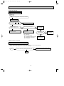
8-1-1. COOL mode of “I FEEL CONTROL”
1. Indoor fan speed control
Indoor fan operates at the set speed by FAN SPEED CONTROL button.
In AUTO the fan speed is as follows.
MSZ09UN
Initial temperature difference
Fan speed
Room temperature minus set temperature : 3 degrees or more·······································High
Room temperature minus set temperature : Between 2 and 3degrees·····························Med.
Room temperature minus set temperature : less than 2 degrees······································Low
Difference between room
temperature and set temperature
during operation
4 deg.
2 deg.
3 deg.
Difference between room
temperature and set
temperature during
operation
MSZ12UN
Fan speed
Initial temperature difference
Room temperature minus set temperature : 4 degrees or more·······································High
Room temperature minus set temperature : Between 2 and 4 degrees····························Med.
4 deg. 7 deg.
Room temperature minus set temperature : less than 2 degree·······································Low
2 deg. 3 deg.
2. Coil frost prevention
1 Temperature control
The operational frequency of the compressor is controlled based on the temperature of the indoor coil thermistor(RT12).
Temperature of indoor coil thermistor:RT12
Operation frequency
approx. 46°F or above
normal
approx. 43°F to 46°F
fixed
approx. 39°F to 43°F
approx. 39°F or below
lowering at the rate of 3Hz/min.
lowering at the rate of 6Hz/min.
Compressor is turned off for 5 minutes when temperature of indoor
coil thermistor continues approx. 39°F or below for 5 minutes or
more.
The indoor fan maintains the actual speed of the moment.
② Time control
When the three conditions as follows have been satisfied for 1 hour and 45 minutes, compressor stops for 3 minutes.
a. Compressor has been continuously operating.
b. Indoor fan speed is Low or Med..
c. Room temperature is below 79˚F.
When compressor stops, the accumulated time is cancelled and when compressor restarts, time counting starts
from the beginning.
Time counting also stops temporarily when the indoor fan speed becomes High or the room temperature exceeds
79°F. However, when two of the above conditions (b.and c.) are satisfied again. Time accumulation is resumed.
25
OB297--1.qxp
04.2.4 4:20 PM
Page 26
ON
ON
Compressor and
Outdoor fan motor
OFF
OFF
ON
Indoor fan motor
(continuously at set speed)
8-1-2. DRY mode of “I FEEL CONTROL”
The system for dry operation uses the same refrigerant circuit as the cooling circuit.
The compressor and the indoor fan are controlled by the temperature.
By such controls, amount of air flow of indoor unit will be reduced in order to lower humidity without much room temperature drop.
MSZ09UN
1. Indoor fan speed control
Indoor fan operates at the set speed by FAN SPEED CONTROL button.
In AUTO fan operation, fan speed becomes Low.
2. The operation of the compressor and indoor/ outdoor fan
Compressor operates by room temperature control and time control.
Set temperature is controlled to fall 4˚F as initial set temperature.
Indoor fan and outdoor fan operate in the same cycle as the compressor.
Operational frequency control at compressor is fixed 30Hz.
Operation time chart
Example
Thermostat
OFF
Indoor fan
Very
Low
ON
ON
OFF
ON
ON
Very
Low
ON
Outdoor fan
Compressor
ON
OFF
OFF
3. Coil frost prevention
• The operation is as same as coil frost prevention during COOL mode of “I FEEL CONTROL”.
• Indoor fan operates at the set speed and the compressor stops for 5 minutes, because protection (Coil frost
prevention) has the priority.
However, when coil frost prevention works while the compressor is not operating, the speed becomes the set speed.
MSZ12UN
1. Indoor fan speed control
Indoor fan operates at the set speed by FAN SPEED CONTROL button.
In AUTO fan operation, fan speed becomes Low.
2. The operation of the compressor and indoor/ outdoor fan
Compressor operates by room temperature control and time control.
Set temperature is controlled to fall 4˚F as initial set temperature.
Indoor fan and outdoor fan operate in the same cycle as the compressor.
Operational frequency control at compressor is fixed 30Hz.
• When the room temperature is 73˚F or over:
When the thermostat is ON, the compressor repeats 8 minutes ON and 3 minutes OFF.
When the thermostat is OFF, the compressor repeats 4 minutes OFF and 1 minute ON.
• When the room temperature is under 73˚F.
When the thermostat is ON, the compressor repeats 2 minutes ON and 3 minutes OFF.
When the thermostat is OFF, the compressor repeats 4 minutes OFF and 1 minute ON.
26
OB297--1.qxp
04.2.4 4:20 PM
Page 27
Operation time chart
Example
Thermostat
ON
ON
OFF
OFF
Indoor fan
OFF
OFF
ON
Outdoor fan
Compressor
8 min.
OFF
ON
OFF
OFF
ON
ON
ON
ON
OFF
3 min. 4 min.
1 min.
3. Coil frost prevention
• The operation is as same as coil frost prevention during COOL mode of “I FEEL CONTROL”.
• Indoor fan operates at the set speed and the compressor stops for 5 minutes, because protection (Coil frost
prevention) has the priority.
However, when coil frost prevention works while the compressor is not operating, the speed becomes the set speed.
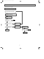
8-1-3. HEAT mode of “I FEEL CONTROL”
1. Indoor fan speed control
(1) In AUTO the fan speed is as follows.
Difference between room
temperature and set
temperature during
operation
Initial temperature difference
Fan speed
Set temperature minus room temperature: 4 degrees or more ··········································High
Set temperature minus room temperature: Between 2 and 4 degrees· ·····························Med.
4 deg. 7 deg.
Set temperature minus room temperature: less than 2 degree··········································Low
2 deg. 3 deg.
(2) Cold air prevention control
MSZ09UN
1 When the compressor is not operating,
(1) if the temperature of indoor coil thermistor RT12 is 64°F or less, the indoor fan stops.
(2) if the temperature of indoor coil thermistor RT12 is more than 64°F, the indoor fan operates at Very Low.
2 When the compressor is operating,
(1) if the temperature of RT12 is 72°F or more, the indoor fan operates at set speed.
(2) if the temperature of RT12 is less than 72°F and
(1) if the temperature of room temperature thermistor RT11 is 59°F or less, the indoor fan stops.
(2) if the temperature of room temperature thermistor RT11 is more than 59°F, the indoor fan operates at Very
Low.
MSZ12UN
When the compressor is operating,
(1) if the temperature of indoor coil thermistor RT12 is less than 64°F or, the indoor fan operates at Very Low.
But if the temperature of room temperature thermistor RT11 is 59°F or less, the fan stops.
(2) if the temperature of indoor coil thermistor RT12 is more than 72°F, the indoor fan operates at set speed.
Indoor coil thermistor
RT12 temperature
Released
Cold Air Prevention
64°F 72°F
Indoor fan speed
Set speed
Very Low or stop
NOTE : If the temperature of RT12 reads from 64°F to 72°F at the air conditioner starting and also after defrosting,
this control works.
27
OB297--1.qxp
04.2.4 4:20 PM
Page 28
(3) Warm air control.
When any condition of 1(a. ~ d.) and the condition of 2 as follows are satisfied at the same time, warm air control
works.
1 a.) when the operation mode has been changed to HEAT mode
b.) when cold air prevention has been released
c.) when defrosting has been finished
d.) when the compressor starts in HEAT mode
2 When the temperature of indoor coil thermistor RT12 is less than 99°F.
When warm air control works, the indoor fan speed changes as follows to blow out warm air gradually.
Gradation of indoor fan speed in initial
<Time condition>
<Indoor fan speed>
less than 2 minutes
2 minutes to 4 minutes
more than 4 minutes
Low
Med.
High
The upper limit of the indoor fan speed in MANUAL is the set speed.
The upper limit of the indoor fan speed in AUTO is the speed decided by indoor fan speed control.
When the temperature of RT12 has been 99°F or more, or when the set speed has been changed, this control is
released and the indoor fan speed is the set speed.
(4) Flow soft control
When the thermostat (compressor) is off, the indoor fan operates as follows.
< RT12 >
< Indoor fan speed >
<MSZ09UN>
less than 64°F
off
NOTE : When the thermostat(compressor) turns on, the indoor
64°F or more
Very Low
fan operates at set speed. But until cold air prevention
<MSZ12UN>
—
Very Low
and warm air control is released, the indoor fan follows
them.
2. High pressure protection
In HEAT mode the indoor coil thermistor RT12 detects the temperature at the indoor heat exchanger and controls the compressor operational frequency to prevent the condensing pressure from increasing excessively.
Temperature of indoor coil thermistor:RT12
Operation frequency
approx. 131°F or below
normal
approx. 140°F to 131°F
lower at the rate of 6Hz/min.
approx. 167°F to 140°F
lower at the rate of 30Hz/min.
approx. 167°F or above
Compressor is turned off and it is turned on 3 minutes later.
3. Overload starting
When the room temperature thermistor reads 64°F or above, the compressor runs with its maximum frequency regulated for
3 minutes after the start-up.
4. Defrosting
(1) Starting conditions of defrosting
When the following three conditions, a), b), and c), are satisfied, the defrosting starts.
a) The defrost thermistor reads 26.6°F or below.
b) The cumulative operation time of the compressor has reached any of the set values: 35, 32 and 35 or more minutes.
c) More than 1 minute have passed since the start-up of the compressor.
w Set value of compressor operation time(hereinafter referred to as defrost interval)
The first defrost interval is 35 minutes long, and the second 32 minutes long.The third and subsequent intervals are
set to be longer, and less frequent, depending on defrosting time.
The third and subsequent defrost intervals follow any of the three patterns 10 minutes longer, the same, 10 minutes
shorter compared with the previous defrost interval … with normal 55 minutes, the longest 115 minutes and the shortest 30 minutes.
(2) Releasing conditions of defrosting
Defrosting is released when any of the following condition is satisfied:
a) The defrost thermistor reads 55°F or above.
b) Defrosting time has exceeded 10 minutes.
c) Some other modes than HEAT mode is set during defrosting.
28
OB297--1.qxp
04.2.4 4:20 PM
Page 29
Time chart of defrosting in HEAT mode (reverse type)
<indoor unit>
Horizontal vane
horizontal
set position
set position
Indoor fan
set speed
Very Low (temperature of indoor coil thermistor > 64°F)
OFF
30
seconds
<outdoor unit>
MAX. Hz
MAX. 79Hz (MSZ12UN)
MAX. 80Hz (MSZ09UN)
MAX. Hz
Compressor normal
OFF
30
seconds
1second
OFF
30
seconds
5 seconds
1second
5
seconds
ON
ON
Outdoor fan
OFF
R.V. coil
(21S4)
ON
ON
OFF
5. R.V. coil control
Heating · · · · · ON
Cooling · · · · · OFF
Dry · · · · · · · · OFF
NOTE: The 4-way valve reverses for 5 seconds right before start-up of the compressor.
(COOL / DRY)
(HEAT)
5 sec.
5 sec.
Compressor
R.V. coil
ON
OFF
ON
OFF
ON
OFF
ON
OFF
29
OB297--1.qxp
04.2.4 4:20 PM
Page 30
6. Outdoor fan motor control
The fan motor turns ON/OFF, interlocking with the compressor.
[ON]
The fan motor turns ON 5 seconds before the compressor starts up.
[OFF]
The fan motor turns OFF 15 seconds after the compressor has stopped running.
ON
5 sec.
15 sec.
Compressor
OFF
ON
Outdoor fan
OFF
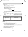
8-2. COOL OPERATION
(1) Press OPERATE/STOP(ON/OFF) button.
OPERATION INDICATOR lamp of the indoor unit turns on with a beep tone.
(2) Select COOL mode with the OPERATION SELECT button.
(3) Press the TEMPERATURE buttons.
(TOO WARM or TOO COOL button) to select the desired temperature.
The setting range is 59 ~ 89˚F
✻ Indoor fan continues to operate regardless of thermostat’s OFF-ON at set speed.
✻ Coil frost prevention is as same as COOL mode of “I FEEL CONTROL”.
8-3. DRY OPERATION
(1) Press OPERATE/STOP(ON/OFF) button.
OPERATION INDICATOR lamp of the indoor unit turns on
with a beep tone.
(2) Select DRY mode with the OPERATION SELECT button.
(3) The microprocessor reads the room temperature and
determines the set temperature. Set temperature is as
shown on the right chart.
Thermostat (SET TEMP.) does not work.
The other operations are same as DRY mode of “I FEEL
CONTROL”.
(4) DRY operation will not function when the room temperature is 55˚F or below.
°F
95
86
77
8-4. HEAT OPERATION
(1) Press OPERATE/STOP(ON/OFF) button.
OPERATION INDICATOR lamp of the indoor unit turns on
with a beep tone.
(2) Select HEAT mode with the OPERATION SELECT button.
(3) Press TEMPERATURE buttons (TOO WARM or TOO
COOL button) to select the desired temperature.
The setting range is 59 ~ 89˚F.
(4) Indoor fan speed control, high pressure protection, defrosting, 4-way valve control are the same as HEAT mode of “I
FEEL CONTROL”.
30
68
59
50
50
59
68
77
86
95°F
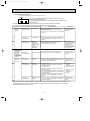
OB297--2.qxp
04.2.4 4:21 PM
Page 31
8-5. FAN MOTOR CONTROL <MSZ09UN>
(1) Rotational frequency feedback control
The indoor fan motor is equipped with a rotational frequency sensor, and outputs signal to the microprocessor to feedback the rotational frequency. Comparing the current rotational frequency with the target rotational frequency (High,
Med., Low) the microprocessor controls SR141 and adjusts fan motor electric current to make the current rotational frequency close to the target rotational frequency. With this control, when the fan speed is switched, the rotational frequency changes smoothly.
Rotational frequency
High
High
Med.
Low
time
(2) Fan motor lock-up protection
When the rotational frequency feedback signal has not output for 12 seconds, (or when the microprocessor cannot
detect the signal for 12 seconds) the fan motor is regarded locked-up. Then the electric current to the fan motor is shut
off. 3 minutes later, the electric current is applied to the fan motor again. During the fan motor lock-up, the OPERATION
INDICATOR lamp flashes on and off to show the fan motor abnormality. (Refer to page 42.)
8-6. AUTO VANE OPERATION
(1) Vane motor drive
These models are equipped with a stepping motor for the horizontal vane. The rotating direction, speed, and angle of
the motor are controlled by pulse signals (approx. 12V) transmitted from indoor microprocessor.
(2) The horizontal vane angle and mode changes as follows by pressing the VANE CONTROL button.
(3) Positioning
The vane is once pressed to the vane stopper below to confirm the standard position and then set to the desired angle.
Confirming of standard position is performed in case of follows.
(a) When the OPERATE/STOP(ON/OFF) button is pressed. (POWER ON/OFF)
(b) When the vane control is changed AUTO to MANUAL.
(c) When the SWING is finished.
(d) When the test run starts.
(e) When the power supply turns ON.
(4) VANE AUTO mode
In VANE AUTO mode, the microprocessor automatically determines the vane angle and operation to make the optimum
room-temperature distribution.
① In COOL and DRY operation
Vane angle is fixed to Angle 1.
➁ In HEAT operation
Vane angle is fixed to Angle 4.
(5) STOP (operation OFF) and ON-TIMER standby
When the following cases occur, the vane returns to the closed position.
(a) When the OPERATE/STOP (ON/OFF) button is pressed (POWER OFF).
(b) When the operation is stopped by the emergency operation.
(c) When the ON-TIMER is in standby.
(6) Dew prevention
During COOL or DRY operation at vane Angle 4 or 5 when the compressor cumulative operation time exceeds 1 hour,
the vane angle automatically changes to Angle 1 for dew prevention.
31
OB297--2.qxp
04.2.4 4:21 PM
Page 32
(7) SWING MODE
By selecting SWING mode with the VANE CONTROL button, the horizontal vane swings vertically. The remote controller
displays “ ”.
(8) Cold air prevention in HEAT operation.
When any of the following conditions occurs in HEAT operation, the horizontal vane angle changes to Angle 1 automatically to prevent cold air blowing on users.
① Compressor is not operating.
➁ Defrosting is performed.
➂ Indoor coil thermistor RT12 reads 75˚F or below.
➃ Indoor coil thermistor RT12 temperature is raising from 75˚F or below, but it does not exceed 82°F.
Horizontal vane
Indoor coil thermistor RT12 temperature
Released
Cold Air Prevention
Set position
75˚F
82˚F
Angle 1
NOTE : If the temperature of RT12 reads from 75˚F to 82 ˚F at the air conditioner starting, this control works.
8-7. TIMER OPERATION
1. How to set the timer.
(1) Press OPERATE/STOP(ON/OFF) button to start the air conditioner.
(2) Check that the current time is set correctly.
NOTE : Timer operation will not work without setting the current time. Initially “AM0:00” blinks at the current time display
of TIMER MONITOR, so set the current time correctly with CLOCK SET button.
(3) Press ON/OFF TIMER buttons to select the operation.
“ON-TIMER” button... AUTO START operation (ON timer)
“OFF-TIMER” button... AUTO STOP operation (OFF timer)
(4) Press HR. and MIN. button (TIME SET button) to set the timer. Time setting is 10-minute units.
HR. and MIN. button will work when “
” or “
” mark is flashing.
These marks disappear in 1 minute.
After setting the ON timer, check that OPERATION INDICATOR lamp of the indoor unit lights.
NOTE1 : Be sure to place the remote controller at the position where its signal can reach the air conditioner even during
TIMER operation, or the set time may deviate within the range of about 10 minutes.
NOTE2 : Reset the timer in the following cases, or the set time may deviate and other malfunctions may occur.
● A power failure occurs.
● The circuit breaker functions.
2. Cancel
TIMER setting can be cancelled with the ON/OFF TIMER buttons.
To cancel the ON timer, press the “ON-TIMER” button.
To cancel the OFF timer, press the “OFF-TIMER” button.
TIMER is cancelled and the display of set time disappears.
PROGRAM TIMER
● The OFF timer and ON timer can be used in combination.
●“
” and “ ” display shows the order of the OFF timer and ON timer operation.
(Example 2) The current time is 11:00 AM.
(Example 1) The current time is 8:00 PM.
The unit turns on at 5:00 PM, and off at 9:00 PM.
The unit turns off at 11:00 PM, and on at 6:00 AM.
PM
PM
AM
PM
NOTE : TIMER setting will be cancelled by power failure or breaker functioning.
32
OB297--2.qxp
04.2.4 4:21 PM
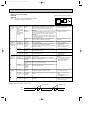
Page 33
8-8. EMERGENCY-TEST OPERATION
In case of test run operation or emergency operation, use the EMERGENCY OPERATION switch on the front of the
indoor unit. Emergency operation is available when the remote controller is missing, has failed or the batteries of remote
controller run down. The unit will start and the OPERATION INDICATOR lamp will light.
The first 30 minutes of operation is the test run operation. This operation is for servicing. The indoor fan speed runs at
High speed and the system is in continuous operation. (The thermostat is ON.)
After 30 minutes of test run operation the system shifts to EMERGENCY COOL / HEAT MODE with a set temperature of
75˚F.
The fan speed shifts to Med. speed.
The coil frost prevention works even in emergency operation, and defrosting cycle as well.
In the test run or emergency operation, the horizontal vane operates in VANE AUTO (
) mode.
Emergency operation continues until the EMERGENCY OPERATION switch is pressed once or twice or the unit receives
any signal from the remote controller. In case of latter normal operation will start.
NOTE : Do not press the EMERGENCY OPERATION switch during normal operation.
• The following indication applies regardless of shape
of the indicator.
MSZ09UN
OPERATION INDICATOR lamp
Press once
<Cool>
Press again
<Heat>
Press once again
<Stop>
EMERGENCY OPERATION
switch
MSZ12UN
EMERGENCY OPERATION
switch
8-9. Main power supply circuit
Outline drawing of main power supply
R64
L62
L63 CT61
X64
DS62
DS61
(~) (+)
(–) (~)
L61
(~) (+)
(–) (~)
POWER
SUPPLY
IPM
P
V
U
+
V
+
NOISE FILTER P.C. BOARD
–
C61
–
C63
R61
W
N
U
W
COMPRESSORE
MICROPROCESSOR
ELECTRONIC CONTROL P.C. BOARD
1. Outline of main power supply circuit
(1) When the electricity is turned on to the outdoor unit
Rush current generates in the main power supply circuit.
To prevent the rush current from running into the main power supply circuit, R64(Current-limiting resistor) absorbs
the rush current.
After the rush current is absorbed, X64(Relay) is ON and the circuit to R64 is short-circuited, then the electricity to
R64 is bypassed.
Following the indoor unit’s operation, X64 is switched to ON or OFF.
33
OB297--2.qxp
04.2.4 4:21 PM
Page 34
(2) At normal operation
Alternating current supplied from power supply is eliminated of any noise by L62(Common mode choke coil) and
L63 (Common mode choke coil). Then DS61(Diode stack) performs full-wave rectification of alternating current and
the alternating current is converted to direct current.
C63(Smoothing capacitor) stabilizes the power supply converted to direct current from alternating current and
supplies it to IPM(Intelligent power module).
Direct current rectified by DS61 is converted to three-phase alternating current by IPM. Microcomputer installed in
the electronic control P.C. board controls frequency and voltage of three-phase alternating current converted by
IPM.
Three-phase alternating current from IPM is supplied to the compressor with frequency and voltage decided by
microcomputer based on various kinds of information. R61(Current-detecting resistor) is installed for overload
protection of the compressor and for protection of IPM.
CT61(Current transformer) measures the current of main power supply circuit.
2. Power factor improvement of power supply
Unlike inverter-less alternating current circuit, the power factor of this inverter circuit is improved by extending the period of the current running in the circuit. C63 is used in this circuit to supply stable direct current voltage. However, in
case only C63 is used for stable supply of direct current, the power factor of power supply is lowered because the period of direct current running in the circuit is short. Therefore, for improvement of power factor, the circuit also uses
C61(Power factor capacitor), L61(Reactor) and DS62(Diode stack) to prepare the direct current circuit to extend the
period of the current running in the circuit.
3. Elimination of electrical noise
Noise filter circuit is formed by L62, L63, and the condenser installed on the noise filter P.C. board. It eliminates the
electrical noise (both common mode and normal mode noise) of alternating current power supply supplied to main
power supply circuit. Noise filter circuit also absorbs electrical noise that is generated in the inverter circuit and prevents it from reaching outside of the unit.
4. IPM
Six power transistors that outputs the direct current waveform as three-phase alternating current waveform, the driving
circuit which operates the power transistors, and the overcurrent detecting circuit which protects the power transistors
are built into the IPM. It can simplify and miniaturize the control circuit.
Symbol
Function
Name
C61
POWER FACTOR CAPACITOR
It improves the power factor of power supply.
C63
SMOOTHING CAPACITOR
It stabilizes the direct current voltage.
CT61
CURRENT TRANSFORMER
It measures the current of main power supply circuit.
DS61
DIODE STACK
It converts the alternating current voltage to direct current voltage.
DS62
DIODE STACK
It is combined with L61 to improve the power factor of power supply.
IPM
INTELLIGENT POWER MODULE
It generates three-phase alternating current and operates compressor.
L61
REACTOR
It is combined with DS62 to improve the power factor of power supply.
L62
COMMON MODE CHOKE COIL
It eliminates and absorbs the electrical noise.
L63
COMMON MODE CHOKE COIL
It eliminates and absorbs the electrical noise.
R61
CURRENT-DETECTING RESISTOR
It detects the current and protects the compressor and IPM.
R64
CURRENT-LIMITING RESISTOR
It absorbs the rush current so not to run into the main power supply
circuit when the electricity is turned on.
X64
RELAY
It short-circuits the circuit to current-limiting resistor when the
compressor operates.
34
OB297--2.qxp
04.2.4 4:21 PM
Page 35
8-10. Operational frequency control of outdoor unit
1. Outline
The operational frequency is as following:
First, the target operational frequency is set based on the difference between the room temperature and the set temperature.
Second, the target operational frequency is regulated by discharge temperature protection, high pressure protection,
electric current protection and overload protection and also by the maximum/minimum frequency.
Maximum/minimum frequency in each operation mode.
COOL
Applied
model
minimum
frequency
rated
frequency
HEAT
maximum
frequency
minimum
frequency
rated
frequency
DRY
maximum
frequency
MSZ09UN
15
64
80
15
76
98
30
MSZ12UN
15
70
85
15
99
125
30
w The maximum frequency in COOL mode varies according to operation hours as shown below.
w However, it is under rating frequency when indoor fan speed is set to MANUAL Low or AUTO Low.
Maximum
frequency
Frequency
1Hr
Rating or under rating frequency
Time: T
2. Control by the difference between the room temperature and the set temperature
The frequency is controlled by the difference between the room temperature and the set temperature.
(1) Frequency when the unit starts operation
At the cooling operation
The difference between
the room temperature and
the set temperature (deg.)
1.8 or less
15
At the heating operation
The difference between
the room temperature and
the set temperature (deg.)
2.3 or less
Operation frequency
(Hz)
Operation frequency
(Hz)
15
15
2.3 to 3.1
15
2.3 to 3.6
20
3.1 to 4.1
20
3.6 to 4.9
1.8 to 2.3
25
4.1 to 5.4
25
4.9 to 5.9
30
5.4 to 5.9
30
5.9 to 6.7
40
5.9 to 6.7
40
MSZ09UN:80/ MSZ12UN:85
6.7 or more
MSZ09UN:98/ MSZ12UN:125
6.7 or more
(2) Frequency after the unit starts operation (Except for the case where the unit operates with the maximum operation
frequency)
In case the difference between the room temperature and the set temperature shown on (1) is changed during
operation or it is not changed for 128 seconds, the compressor operates with new operation frequency that is
calculated from actual operation frequency and the rate of change by fuzzy control.
35
OB297--2.qxp
04.2.4 4:21 PM
Page 36
3. Frequency control by estimated discharge temperature (for protecting the discharge temperature in case the
estimated discharge temperature is 212 °F or higher)
By calculating the difference between the current discharge temperature and the discharge temperature 15 seconds
before, a discharge temperature in one minutes is estimated. As a result, the frequency and LEV are controlled as
shown the table below.
Esimated discharge
temperature(°F )
Frequency control
LEV control
241 or higher
Lowered by 12Hz
Opened by 30 pulse
232 to 241
Lowered by 6Hz
Opened by 20 pulse
Regulated so that the
219 to 232
frequency will not rise
Opened by 20 pulse
212 to 219
No correction
Opened by 20 pulse
212 or lower
No correction
No correction
8-11. Optimal voltage control
The purpose of optimal voltage control is to operate the compressor at optimal
Power factor
voltage that meets the load detected by the power factor of the compressor.
1. Optimal
As shown on the right the efficiency (ratio of output against input) of the
motor in the compressor becomes optional when the sliding (ratio of difference between the actual number of rotation and the number of synchronous
rotation of motor) is one fixed value. The value of sliding can be calculated
from the power factor since the sliding and the power factor are mutually
related as shown the table on the right. To make the value of sliding so that
the efficiency of motor is optimal, the power factor of the compressor is
detected. Then the detected power factor is controlled so that its efficiency
slip
can be high. As a result, it is possible to operate the compressor at optimal 1
voltage.
efficiency
0
2. How to determine the optimal voltage
Compare the detected power factor with the target power factor so that the efficiency of motor is optimal, the voltage
correction value is changed and the optimal output voltage is determined.
Optimal output voltage[V]= Standard voltage at certain frequency [V]x voltage correction value(%)
Target power factor minus detected power factor
(Calculated value is supposed to be "A".)
Calculation of voltage
correction value (%)
A[-2%
Previous voltage correction value minus 1
-2%<A<+2%
Same as previous voltage correction value
A]+2%
Previous voltage correction value plus 1
36
OB297--2.qxp
04.2.4 4:21 PM
Page 37
8-12. Expansion valve control (LEV control)
general operation
standard
specification
(1) Outline of LEV control
The LEV basic control is comprised of setting LEV opening degree to the standard opening degrees set for each operational frequency of the compressor. However, when any change in indoor/outdoor temperatures or other factors cause
air conditioning load fluctuation, the LEV control also works to correct LEV opening degree based on discharge temperature (Shell temperature) of the compressor, developing the unit’s performance.
Control range
from min. 33 pulse to max. 500 pulse.
Actuating speed
LEV opens 40 pulse/sec. and close 90 pulse/sec.
Opening degree adjustment
LEV opening degree is always adjusted in opening direction.
(When reducing the opening degree, LEV is once overclosed, and then adjusted to the proper degree by opening.
Unit OFF
LEV remains at max. opening degree (reaches max. opening
degree approx. 15 minutes after compressor stops)
Remote controller ON
LEV is positioned. (first full-closed at zero pulse and then
positioned.)
During 2 to 13 minutes after compressor starts
Opening degree is adjusted according to standard opening
degree.
(Standard opening degree is set for each rotational frequency of compressor)
More than 13 minutes have passed since compressor
start-up
LEV opening degree is corrected to get target discharge
temperature of compressor.
(For discharge temperature lower than target temperature,
LEV is corrected in closing direction.)
(For discharge temperature higher than target temperature,
LEV is corrected in opening direction.)
wIt may take more than 30 minutes to reach target temperature, depending on operating conditions.
Thermostat OFF
LEV starts to open every 3 pulse/sec.
from
the same opening degree as that when the Unit turned OFF
(and becomes full-opened after approx. 15 minutes.)
Thermostat ON
LEV is controlled in the same way as that is after the compressor has started up.
Defrosting in HEAT mode
LEV is adjusted to open 500 pulse.
37
OB297--2.qxp
04.2.4 4:21 PM
Page 38
(2) Time chart
Air conditioner ON
Air conditioner OFF
(thermostat off)
LEV opening degree
Positioning
Opening degree is
corrected according
to discharge
temperature.
Standard
opening
degree
Commanded
to open
Time
ON
OFF Time
(3) Control data
(a) Reference value of target discharge temperature
(COOL/HEAT °F)
A
B
C
D
E
F
MSZ09UN
136/120 145/136 156/151 165/160
–/169
–/–
MSZ12UN
126/118 129/135 138/151 151/160
–/169
–/172
Target discharge temperature
The operational frequency
of the compressor
13 min.
F
E
D
C
B
A
30
50
90
70
110
130 (Hz)
The operational frequency of the compressor
MSZ09UN
In COOL mode, the two indoor coil thermistor (one main and one sub) sense temperature ununiformity (super heat)
at the heat exchanger, And when temperature difference have developed, the indoor coil thermistors adjust LEV
opening to get approximate 16 degrees lower temperature than the target temperature in the table above, thus
diminishing super heat.
A
MSZ09UN
MSZ12UN
B
C
D
120/100 170/130 210/160 230/180
190/120 220/170 250/190 280/210
E
F
–/200
–/–
–/230
–/240
LEV opening degree
(b) Reference value of LEV standard degree opening
(COOL/ HEAT pulse)
F
E
D
C
B
A
30
50
70
90
110
130 (Hz)
The operational frequency of the compressor
38
OB297--2.qxp
04.2.4 4:21 PM
9
Page 39
SERVICE FUNCTIONS
MSZ09UN
MSZ12UN
MUZ09UN
MUZ12UN
9-1. CHANGE IN DEFROST SETTING
<JS> When the JS wire of the outdoor electronic control P.C. board is cut, the defrost temperature will be changed.
(Refer to page 58.)
Jumper wire
Change point
JS
Deforst finish temperature changes from 55°F to 59°F.
9-2. TIMER SHORT MODE
For service, set time can be shortened by short circuit of JPG and JPS the indoor electronic control P.C. board.
The time will be shortened as follows. (Refer to page 56 or 57.)
Set time : 1 minute ➔ 1-second
Set time : 3 minute ➔ 3-second (It takes 3 minutes for the compressor to start operation. However, the starting time is
shortened by short circuit of JPG and JPS.)
9-3. P.C. BOARD MODIFICATION FOR INDIVIDUAL OPERATION
A maximum of 4 indoor units with wireless remote controllers can be used in a room.
In this case, to operate each indoor unit individually by each remote controller, P.C. boards of remote controller must be
modified according to the indoor unit number.
How to modify the remote controller P.C. board
Remove batteries before modification.
The board has a print as shown below :
NOTE : For remodelling, take out the batteries and press the
OPERATE/STOP(ON/OFF)button
twice or 3 times at first.
After finish remodelling, put back
the batteries then press the
RESET button.
The P.C. board has the print “J1” and “J2”. Solder “J1” and “J2” according to the number of indoor unit as shown in Table 1.
After modification, press the RESET button.
Table 1
1 unit operation
2 units operation
3 units operation
4 units operation
No. 1 unit
No modification
Same as at left
Same as at left
Same as at left
No. 2 unit
–
Solder J1
Same as at left
Same as at left
No. 3 unit
–
–
Solder J2
Same as at left
No. 4 unit
–
–
–
Solder both J1 and J2
How to set the remote controller exclusively for particular indoor unit
After you turn the breaker ON, the first remote controller that sends the signal to the indoor unit will be regarded as the
remote controller for the indoor unit.
The indoor unit will only accepts the signal from the remote controller that has been assigned to the indoor unit once they are
set. The setting will be cancelled if the breaker has turned off, or the power supply has shut down.
Please conduct the above setting once again after the power has restored.
39
OB297--2.qxp
04.2.4 4:21 PM
Page 40
9-4. AUTO RESTART FUNCTION
When the indoor unit is operated with the remote controller, the signals of the operation mode, the set temperature,
and the fan speed are sent from the indoor electronic control P.C. board and memorized in the auto restart assembly.
When the main power is turned off and then turned back on, the unit restarts automatically in the memorized set
conditions approximately after 3 minutes.
How to release “AUTO RESTART FUNCTION”
1 Turn off the main power for the unit.
2 Pull out the indoor electronic control P.C. board and the display P.C.board. (Refer to page 61 or 64.)
3 <MSZ09UN>
Solder the Jumper wire or the Resistor 220Ω to the JR07 on the indoor electronic control P.C.board.
(Refer to page 56.)
<MSZ12UN>
Disconnect the AUTO RESTART ASSY from CN104, and solder the Jumper wire to JHA on the indoor electronic control
P.C. board.(Refer to page 57.)
Operation
1 If the main power (115V AC) has been cut, the operation settings remain.
2 After the power is restored, the unit restarts automatically according to the memory.(However, it takes at least 3 minutes
for the compressor to start running.)
MSZ12UN
C111
MSZ09UN
C11
CN201
SW1
CN113CN151
JHA
CN104
CN112 SW
IC101
RA102
CN102 CN101
IC152
CN112
IC101
BZ
CN121
CN211
CN151
CN111
CN201
JR07
NOTE:
•The operation settings are memorized when 10 seconds have passed after the indoor unit was operated with the remote
controller.
•If the main power is turned off or a power failure occurs while AUTO START/STOP timer is active, the timer setting is
cancelled.
•If the unit has been off with the remote controller before power failure, the auto restart function does not work as the
power button of the remote controller is off.
•To prevent breaker off due to the rush of starting current, systematize other home appliances not to turn on at the same time.
•When some air conditioners are connected to the same supply system, if they are operated before power failure, the
starting current of all the compressors may flow simultaneously at restart.
Therefore, the special counter-measures are required to prevent the main voltage-drop or the rush of the starting current
by adding to the system that allows the units to start one by one.
40
OB297--2.qxp
04.2.4 4:21 PM
10
Page 41
TROUBLESHOOTING
MSZ09UN
MSZ12UN
MUZ09UN
MUZ12UN
10-1. Cautions on troubleshooting
1. Before troubleshooting, check the following:
1) Check the power supply voltage.
2) Check the indoor/outdoor connecting wire for mis-wiring.
2. Take care the following during servicing.
1) Before servicing the air conditioner, first be sure to turn off the remote controller to stop the unit, and then after confirming the horizontal vane is closed, turn off the breaker and / or disconnect the power plug.
2) Be sure to turn OFF the power supply before removing the front panel, the cabinet, the top panel, and the electronic
control P.C. board.
3) When removing the electronic control P.C. board, hold the edge of the board with care NOT to apply stress on the
components.
4) When connecting or disconnecting the connectors, hold the housing of the connector. DO NOT pull the lead wires.
Housing point
Lead wiring
3. Troubleshooting procedure
1) First, check if the OPERATION INDICATOR lamp on the indoor unit is flashing on and off to indicate an abnormality.
To make sure, check how many times the abnormality indication is flashing on and off before starting service work.
2) Before servicing check that the connector and terminal are connected properly.
3) If the electronic control P.C. board is supposed to be defective, check the copper foil pattern for disconnection and
the components for bursting and discoloration.
4) When troubleshooting, refer to the flow chart on page 42 and the check table on page 43.
4. How to replace batteries
Weak batteries may cause the remote controller malfunction.
In this case, the remote controller can be repaired only by the battery replacement. To operate the remote controller normally, replace the batteries in the following order.
This remote controller has the RESET button. After refilling new batteries, press the RESET button with tip end of ball
point pen or the like, and then use the remote controller.
1 Remove the front lid and replace batteries.
Then re-attach the front lid.
2 Press the RESET button.
Insert the negative pole
of the batteries first.
Check if the polarity of
the batteries are correct.
RESET button
NOTE : If the RESET button is not pressed, the remote controller may not operate correctly.
41
OB297--2.qxp
04.2.4 4:21 PM
Page 42
10-2. Troubleshooting procedure
The following procedure facilitates identifying defective points.
Details of OPERATION INDICATOR lamp flashing are located on page 43.
Start
Indoor unit
operates.
Outdoor unit
doesn't
operate.
Indoor unit
does'nt receive
the signal from
remote controller.
Outdoor unit
operates in
only Test Run
operation.
Outdoor unit
does'nt
operate
even in
Test Run
operation.
Indoor unit
operates, when
the EMERGENCY
OPERATION
switch is pressed.
Indoor unit
doesn't operate,
when the
EMERGENCY
OPERATION
switch is pressed.
Check room
temperature
thermistor.
Refer to
"Test point
diagram and
voltage" on
page 56 or 57.
Refr to A
"How to check
inverter/
compressor"
on page 47.
Refer to H
"Check of
remote controller
and receiver
P.C. board"
on page 50.
Refer to I
"Check of indoor
electronic control
P.C. board"
on page 51.
2-time flash
3-time flash
1-time flash
Cause:
Cause: Indoor/ Cause:
Indoor unit
Indoor unit
Outdoor unit
•
Trouble
of
•
Trouble
of
• Mis-wiring
room temperindoor fan
• Serial signal
ature/ indoor
motor
error
coil thermistor
Refer to P
"Checking
mis-wiring and
serial signal
error"
on page 55.
Check room
temperature
thermistor and
indoor coil
thermistor.
Refer to
"Test point
diagram and
voltage" on
page 56 or 57.
Refer to G
"Check of
indoor fan
motor"
on page 49.
42
MSZ12UN
When the remote
controller is
pressed or when
the EMERGENCY
OPERATION
switch is pressed,
the indoor fan
does not rotate
with OPERATION
INDICATOR lamp
on.
OPERATION
INDICATOR
lamp on the
indoor unit is
flashing on and
off.
5-time flash
Cause:
Outdoor unit
• Outdoor
power
system
abnormality
6-time flash
Cause:
Outdoor unit
• Trouble of
thermistor
in outdoor
unit
Refer to A
"How to check
inverter/
compressor"
on page 47.
Refer to J
"Check of
outdoor
thermistors"
on page 51.
7-time flash
Cause:
Outdoor unit
• Trouble of
outdoor
control
system
Replace the
outdoor
electronic
control
P.C. board.
OB297--2.qxp
04.2.4 4:21 PM
Page 43
1. Troubleshooting check table
• The following indication applies regardless of shape of the indicatior.
flashing
· Flashing of the OPERATION INDICATOR lamp (on the left-hand side)
indicates possible abnormalities.
· The OPERATION INDICATOR lamp (on the left-hand side) is lighted during
normal operation.
· Flashing of the operation indicator lamp (on the left-hand side) indicates possible abnormalities.
· The operation indicator lamp (on the left-hand side) is lighted during normal operation.
Operation Indicator
No.
Symptom
Outdoor unit
does not
operate.
Operation indicator lamp
repeated flashes
every 0.5 seconds
Abnormal point
Mis-Wiring
1
Checkpoint
Refer to 'Checking
serial signal error' on
page 55.
3 minutes after power supply turns ON, when serial signal is
not received.
2
1-time flash
2.5 seconds OFF
Serial signal
When indoor electronic control P.C. board does not
receive serial signals from outdoor unit for 4 to 5
seconds,
2-time flash
2.5 seconds OFF
Indoor coil
thermistor
Auxiliary indoor
coil thermistor
Room
temperature
thermistor
Indoor electronic control P.C. board constantly
detects resistance every 8 seconds.
When thermistor shorts or opens.
3-time flash
2.5 seconds OFF
Indoor fan motor
5-time flash
2.5 seconds OFF
6-time flash
2.5 seconds OFF
3
4
Indoor fan
motor repeats
12 seconds
ON and 3
minutes OFF.
When the
indoor fan
motor breaks,
the fan keeps
stopping.
5
Outdoor unit
does not
operate.
7-time flash
2.5 seconds OFF
Refer to the
characteristics of main
indoor coil thermistor,
sub indoor coil
thermistor, and room
temperature thermistor
on page 56 or 57.
When rotational frequency feedback signal is not
emit during 12-second indoor fan operation.
Refer to G "Check of
indoor fan motor" on
page 49.
Outdoor power
system
When compressor has stopped due to overcurrent
protection or start-up failure protection 3 times in a
row within 1 minute after start-up.
Refer to A "How to
check inverter/
compressor" on page
47.
Outdoor
thermistors
<Thermistor short>
Thermistors are abnormal when they short after
compressor start-up.
<Thermistor open>
Thermistors are abnormal when they open after
compressor start-up.
Discharge temperature thermistor is abnormal when
open circuit is detected more than 10 minutes after
compressor start-up.
Defrost thermistor is abnormal when open circuit is
detected more than 1 minutes after compressor
start-up.
When nonvolatile memory data cannot be read properly
on outdoor control P.C. board, outdoor unit stops and
restarts 3 minutes later.
· Shortage of
refrigerant
· Outdoor electronic
control P.C. board
6
7
Detection method
When the unit operates by the remote controller or
emergency operation switch at 3 minutes after the main
power supply is turned on.
Outdoor control
system
Refer to J "Check
of outdoor
thermistors" on
page 51.
Replace outdoor
electronic control P.C.
board.
When the indoor unit has started operation and the above detection method has detected an abnormality (the first
detection after the power ON), the indoor electronic control P.C. board turns OFF the indoor fan motor with the
OPERATION INDICATOR lamp flashing.
43
OB297--2.qxp
04.2.4 4:21 PM
Page 44
(Outdoor LED indication table)
MUZ09UN
MUZ12UN
<Outdoor electronic control P.C. board>
NOTE 1. The location of LED is illustrated at the right figure.
2. LED lights up during normal operation.
LED
Transistor
module
Hybrid
IC
flashing
transformer
No.
1
Symptom
LED indication
Outdoor unit
does not
operate
1-time flash every
2.5 seconds
NOTE:
For abnormality
location, refer to
'Indoor
troubleshooting
check table' on
page 43.
2
5
'Outdoor unit
stops and
restarts 3
minutes later'
is repeated
Checkpoint
· Refer to A 'How to check inverter/
compressor' on page 47.
Outdoor
thermistors
MUZ09UN
When discharge temperature thermistor, defrost thermistor or
fin temperature thermistor shorts or opens during compressor
running, compressor stops and restarts 3 minutes later.
· Refer to J 'Check of outdoor
thermistors' on page 51.
MUZ12UN
When discharge temperature thermistor, defrost thermistor or
fin temperature thermistor shorts or opens during compressor
running, compressor stops.
When nonvolatile memory date cannot be read properly,
compressor stops and restarts 3 minutes later.
Replace outdoor electronic control
P.C. board.
2-time flash
Overcurrent
2.5 seconds OFF protection
When 29A current flows into IPM, compressor stops and
restarts 3 minutes later.
Refer to A 'How to check inverter/
compressor on page 47.
3-time flash
Discharge
2.5 seconds OFF temperature
overheat
protection
When discharge temperature thermistor exceeds 241°F,
compressor stops and restarts 3 minutes later.
(Compressor restarts when discharge temperature thermistor
reads 212°F or below.)
· Check refrigerant circuit and
refrigerant amount.
· Refer to J 'Check of outdoor
thermistors' on page 51.
When temperature at heat sink exceeds 182°F or outdoor
Fin temperature
· Check around outdoor unit.
4-time flash
2.5 seconds OFF thermistor overheat electronic control P.C. board exceeds 172°F, compressor stops · Check outdoor unit air passage.
and restarts 3 minutes later.
protection
6
High pressure
5-time flash
2.5 seconds OFF protection
7
8
Detection method
When compressor has stopped by over current protection
within 1 minute after compressor start-up 3 times in a row,
compressor stops and then restarts 3 minutes later.
Outdoor control
system
3
4
Abnormal point
Outdoor power
system
Outdoor unit
operates
(at low
frequency)
When indoor coil thermistor exceeds 167°F, compressor stops
and restarts 3 minutes later.
Frequency drop by When current from power outlet exceeds 9A, compressor
1-time flash
2-5 seconds OFF current protection frequency lowers.
Frequency drop by When indoor coil thermistor exceeds 131°F in HEAT mode,
3-time flash
compressor frequency lowers.
2-5 seconds OFF high pressure
protection
9
· Check refrigerant circuit and
refrigerant amount.
· Check stop valve.
The unit is normal, but check the
following.
· Check if indoor filters are clogged
· Check if refrigerant is short.
· Check if indoor/outdoor unit air
outlets are short cycled.
Frequency drop by When indoor coil thermistor reads 43°F or below in COOL
defrosting in COOL mode, compressor frequency lowers.
mode
4-time flash
Frequency drop by, When discharge temperature thermistor exceeds 232°F,
2-5 seconds OFF discharge
compressor frequency lowers.
temperature
protection.
10
Outdoor unit
operates
Power factor
6-time flash
2-5 seconds OFF detection
When power factor of compressor is not detected.
w In this case, compressor continues running.
12
Low discharge
7-time flash
2-5 seconds OFF temperature
protection
When discharge temperature has been 122°F or below for 20
minutes.
· Refer to O 'Check of LEV' on
page 54.
· Check refrigerant circuit and
refrigerant amount.
13
9-time flash
inverter check
2-5 seconds OFF mode
When connector of compressor disconnect, inverter check
mode starts.
· Check if connector is connected.
· Refer to A 'How to check inverter/
compressor on page 47.
11
The flashing frequency shows the number of times the LED blinks after every 2.5-second OFF.
(Example) When the flashing frequency is “2”.
0.5-second ON
ON
2.5-second OFF
2.5-second OFF
OFF
44
Check compressor wiring.
0.5-second ON
OB297--2.qxp
04.2.4 4:21 PM
Page 45
2. Trouble criterion of main parts
Check method and criterion
Part name
Figure
Room temperature
thermistor(RT11) Measure the resistance with a tester. (Part temperature 50°F ~ 86°F)
Main indoor coil
thermistor(RT12)
Normal
8kΩ ~ 20kΩ
Sub indoor coil
thermistor(RT13)
Abnormal
Open or short-circuit
Measure the resistance with a tester. (Part temperature 14°F ~ 104°F)
Defrost
thermistor(RT61)
Normal
5kΩ ~ 60kΩ
Abnormal
Open or short-circuit
Disconnect the connector and measure the resistance with a tester.
Before measurement, hold the thermistor with your hands to warm it up.
(Part temperature : 32°F~104°F)
Discharge
temperature
thermistor
(RT62)
Normal
150kΩ ~ 600kΩ
Abnormal
Open or short-circuit
Disconnect the connector and measure the resistance with a tester.
(Part temperature :32°F~104°F)
Normal
Abnormal
30kΩ ~ 180kΩ
Open or short-circuit
Fin temperature thermistor
(RT64)
Measure the resistance between the terminals with a tester.
(Part temperature14°F ~ 104°F)
WHT
RED BLK
2
Terminal
U-V
U-W
V-W
Compressor
(MC)
Normal
Abnormal
0.92~1.14Ω
Open or
short-circuit
3
1
W
V
U
Compressor motor
Measure the resistance between the terminals with a tester.
(Part temperature 50°F ~ 86°F)
Motor part
MSZ09UN
Sensor part
INNER FUSE
262I 4°F CUT
OFF
Normal
MSZ09UN
76~83 Ω
70~76 Ω
WHT
Abnormal
Open or
short-circuit
RED
MAIN
BLK
Measure the voltage Power ON.
Normal
Color of lead wire
4.5 ~ 5.5V
BRN-YLW
YLW-GRY
Color of
lead wire
WHT-BLK
BLK-YLW
YLW-BLU
BLU-BRN
BRN-RED
1
2
3
FUSE
AUX.
YLW
GRY
Motor part
Indoor fan
motor(MF)
Color of
lead wire
WHT-BLK
BLK-RED
BRN
1
2
3
Abnormal
(When fan revolved one time)
0V ➔ 5V ➔ 0V (Approx.)
Normal
MSZ12UN
65~72 Ω
8~10 Ω
4~ 6 Ω
5~ 7 Ω
28~31 Ω
45
Remain 0V or 5V
Abnormal
MSZ12UN
BLK
AUX.1
Open or
short-circuit
YLW
AUX.2
BLU
AUX.3
BRN
AUX.4
RED
MAIN
FUSE
ORN
WHT
OB297--2.qxp
04.2.4 4:21 PM
Page 46
Check method and criterion
Part name
Outdoor fan
motor(MF61)
INNER
PROTECTOR
266I 14°F OPEN
174I 30°F CLOSE
Figure
Measure the resistance between the terminals with a tester.
(Part temperature14°F ~ 104°F)
BLK
Color of lead wire
WHT-BLK
BLK-RED
Normal
169~208Ω
246~301Ω
Abnormal
Open or
short-circuit
Measure the resistance between the terminals with a tester.
(Part temperature 50°F ~ 86°F)
P
AUX.
RED
MAIN
WHT
MSZ09UN
RED
ROTOR
YLW
Vane motor(MV)
MSZ09UN
BRN-other one
282 ~ 306Ω
Normal
MSZ12UN
RED-other one
358 ~ 388Ω
Abnormal
Open or
short-circuit
BRN
GRN
ORN
MSZ12UN
PNK
ROTOR
ORN
RED
Measure the resistance between the terminals with a tester.
(Part temperature :14°F~104°F)
Normal
Abnormal
1.2kΩ ~ 1.6kΩ
Open or short-circuit
Expansion
valve (LEV)
Measure the resistance with a tester.
(Part temperature : 14°F~104°F)
Normal
(CN724)
WHT-RED
RED-ORN
39 ~ 56Ω
YLW-BRN
BRN-BLU
Abnormal
Open or
short-circuit
WHT6
RED1
ORG4
LEV
YLW5
BRN2
R.V. coil
(21S4)
BLU
BLU3
YLW
P:INNER PROTECTOR
46
OB297--2.qxp
04.2.4 4:21 PM
Page 47
When OPERATION INDICATOR lamp flashes 5-time.
Outdoor unit does not operate.
A How to check inverter/ compressor
Disconnect the connector
between compressor and
IPM.
Check the voltage
between terminals.
Are voltages
balanced?
Refer to B “Check of open phase” on page 47.
No
Replace the outdoor
electronic control P.C.
board.
Yes
Check the
compressor.
Refer to D “Check of compressor” on page 48.
B Check of open phase
Be sure to use the analog voltmeter for measurement.
With the connector between compressor and IPM disconnected, activate the inverter and measure the balance of voltage between terminals.
Operation
mode
COOL
HEAT
Model
MSZ09UN
MSZ12UN
MSZ09UN
MSZ12UN
Operational
frequency
[Hz]
Output
voltage
[V]
64
70
120
130
110
58
Voltmeter indication
BLK-WHT
<< Operation method>>
Start heating operation by pressing the EMERGENCY OPERATION switch
on the indoor unit. (test-run mode)
<<Measurement point>>
at 3 points
BLK-WHT
w Measure AC voltage between
BLK-RED
the lead wires at 3 points.
WHT-RED
<<Judgment>>
Balanced································normal
Unbalanced···························abnomal (open phase)
Shutdown by overcurrent·······abnormal (short)
BLK-RED
ACV
WHT-RED
ACV
300
ACV
300
BLK-WHT
BLK-RED
ACV
300
WHT-RED
ACV
ACV
300
300
300
NOTE 1. Measure AC voltage, at 3 points more than one minute after the outdoor fan motor starts running.
2. The output voltage values in above table have tolerance withinJ i20%.
C Check of open IPM
Disconnect the connector between compressor and IPM, and
measure resistance between terminals on the IPM.
<<Measurement point>>
at 6 points
BLK-WHT, WHT-BLK
BLK-RED, RED-BLK
w Measure resistance between
WHT-RED, RED-WHT
the lead wires at 3 points
<<Judgment>>
Infinite ["]···········normal
0~dozens of ······abnormal (short)
ohmmeter indication
"
X1
normal
(infinite)
"
X1
47
Normal
(Balanced)
abnormal
(0~dozens of ")
Abnormal
(unbalanced)
OB297--2.qxp
04.2.4 4:21 PM
Page 48
D Check of compressor
Start
E 'Check of compressor
winding' on page 48.
Is compressor normal?
No
Replace the compressor.
Yes
F 'Check of compressor
operation time' on page 48.
Does the compressor operate
continuously?
Yes
No
Ok
Is the compressor operation
time more than 10 seconds?
No
Replace the compressor.
Yes
Check the refrigerant circuit.
E Check of compressor winding
Ohmmeter indication
Disconnect the connector between compressor and IPM, and measure
resistance between the compressor terminals.
<<Measurement point>>
at 3 points
BLK-WHT
BLK-RED
w Measure resistance between the
WHT-RED
lead wires at 3 points.
<<Judgment>>
0.92 to 1.14" at -14°F to 104°F of part temperature
0["] ···············abnormal [short]
Infinite["] ·······abnormal [open]
NOTE 1. Be sure to zero the ohmmeter before measurement.
2. Winding resistance for each phase is 1.05" at 68°F.
WHT
"
X1
normal
(1~several ")
2
RED BLK
3
1
W
V
U
"
X1
abnormal
(0" ····· short)
X1
abnormal
(infinite····· open)
Compressor motor
"
F Check of compressor operation time
0 sec.
Connect the compressor and activate the inverter. Then measure
the time until the inverter stops due to overcurrent.
<<Operation method>>
Start heating or cooling operation by pressing the EMERGENCY
OPERATION switch on the indoor unit. (Test-run mode)
<<Measurement>>
Measure the time from the start of outdoor fan running till the
stop of the inverter due to overcurrent.
<<Judgment>>
For reference
0~10 seconds·····················abnormal (short)
10~60 seconds···················abnormal (compressor lock-out)
60 seconds~5 minutes·······abnormal (refrigerant circuit defect)
more than 5 minutes···········normal
10 sec.
Outdoor fan starts
Abnormal
(Compressor winding short or layer short)
Abnormal
(Compressor lock-out)
60 sec.
Abnormal
(Refrigerant circuit defect, etc.)
5 min.
48
Normal
OB297--2.qxp
04.2.4 4:21 PM
Page 49
When OPERATION INDICATOR lamp flashes 3-time.
Indoor fan does not operate.
G Check of indoor fan motor
Turn OFF the power supply.
Check connector (Fan motor) visually.
No
Are lead wires connected?
Yes
Is soldered point of the connector
correctly soldered?
Yes
Re-connect the lead wires.
Disconnect lead wires from connector (Fan motor).
Measure resistance between lead wires
No.1 and No.3 and then No.2 and No.3 (MSZ09UN).
No.1 and No.4 and then No.3 and No.4 (MSZ12UN).
{
MSZ12UN
No
(others)
No
Re-solder it.
}
Replace the indoor electronic control P.C. board.
Is resistance 0 (short circuit) or ∞ (open circuit)?
Yes ( 0 or ∞ )
MSZ09UN
Repair or replace the indoor fan motor.
No
49
Insert screwdriver into air outlet and
rotate indoor fan (motor) slowly for
1 revolution or more, and measure
voltage between CN 121 1-2 .
Does voltage repeat 0V
DC and more than 5V?
Yes
OB297--2.qxp
04.2.4 4:21 PM
Page 50
Indoor unit operates by pressing the EMERGENCY OPERATION switch, but does not operate with the remote controller.
H Check of remote controller and receiver P.C. board
wCheck if the remote controller is exclusive for this air conditioner.
wIn case of replacing the receiver P.C. board of MSZ09UN, replace the indoor electronic control P.C. board with it because they are unified.
Switch on the remote controller.
Is LCD display on the remote controller displayed?
No
Replace the batteries.(Refer to page 41.)
(not clear)
Yes
Remove the batteries, then set them back
and press the RESET button. Check if the
unit operates with the remote controller.
Does the unit operate with the
remote controller?
No
Turn on a radio to AM and press switch on
the remote controller.
Yes
Is noise heard from radio?
OK
No
Replace the remote controller.
Yes
Are there any fluorescent lights of
inverter or rapid-start type within
the range of 3.28ft.?
Yes
● Re-install the unit away from lights.
● Attach a filter on receiving part.
No
MSZ12UN
No
Connect properly.
MSZ09UN
Is the connector connecting receiver
P.C. board and indoor electronic control P.C. board properly connected?
Yes
Replace the receiver P.C. board.
No
Does the unit receive signal of
ON/OFF with the remote controller
and emit a beep tone?
Yes
OK
Connect properly.
No
Is auto restart assembly properly
connected ?
Yes
Replace the auto restart assembly.
No
Does the unit receive signal of
ON/OFF with the remote controller and
emit a beep tone?
Yes
OK
Replace the indoor electronic
control P.C. board.
No
Does the unit receive signal of
ON/OFF with the remote controller
and emit a beep tone?
Yes
OK
50
Replace the power monitor, receiver
P.C. board with the indoor electronic
control P.C. board.
OB297--2.qxp
04.2.4 4:21 PM
Page 51
The unit doesn’t operate with the remote controller.
Also, the OPERATION INDICATOR lamp doesn’t light up by pressing the EMERGENCY OPERATION switch.
I Check of indoor electronic control P.C. board
Check the both “parts side” and “pattern
side” of indoor electronic control P.C.
board visually.
Turn OFF the power supply.
Disconnect indoor fan motor connector CN211(MSZ09UN)
and vane motor connector CN151 from the indoor
electronic control P.C. board and turn ON the power supply.
Does the unit operate with the remote controller or
No
the OPERATION INDICATOR lamp light up
by pressing the EMERGENCY OPERATION switch?
Yes
Turn OFF the
power supply.
Replace the vane
motor.
Turn OFF the
power supply.
Replace the fuse.
Yes
Is winding
resistance of
vane motor 0 "?
Yes
Be sure to check both resistances.
Is winding
resistance of
fan motor 0 "?
Yes
Is fuse(F11) blown?
No
No
Replace the indoor
electronic control
P.C. board.
Be sure to check both fuse
and varistor in any case.
Is varistor(NR11) burnt?
No
No
Yes
Replace the varistor.
Replace the fan
motor.
When OPERATION INDICATOR lamp flashes 6-time.
The thermistors in the outdoor unit are abnormal.
J Check of outdoor thermistors
Disconnect the connectors CN641 and CN642 from the outdoor electronic control P.C. board.
Check the characteristics of each thermistor.
(
)
Defrost
thermistor
RT61
1 Connect CN641 and
CN642.
2 Disconnect the
connector between
the compressor and
IPM.
Measure
resistance
between CN
6411 and 2.
(
Discharge
temperature
thermistor
RT62
)
Measure
resistance
between CN
6413 and 4.
(
Fin
temperature
thermistor
RT64
)
Does the
resistance of the
Yes
thermistor have
the characteristics
on page 45?
No
Turn ON the
power supply to
indoor unit and
press the
EMERGENCY
OPERATION
switch.
Replace the
thermistor.
Replace the outdoor
electronic control
P.C. board.
No
Does the unit
operate 10 minutes
or more?
Yes
Is LED in the
outdoor electronic
control P.C. board
flashing 5 minutes?
Measure
resistance
between CN
6421 and 2.
No
Reconnect the
connector.
51
Yes
OB297--2.qxp
04.2.4 4:21 PM
Page 52
Cooling operates when heating is expected.
K Check of R.V. coil
Measure resistance of the R.V. coil to check if it is defective or not.
If the connector CN 721 is not connected or the R.V. coil is open, the voltage occurs between the terminals even when the control is OFF.
R.V. coil
208/230V AC
1
2
CN721
Relay P.C. board
Disconnect the connector between the
compressor and transistor module.
Turn ON the power supply to indoor unit,
and press twice (heating) the
EMERGENCY OPERATION switch.
Is there voltage of
208/230V AC
between CN 721 1
and 2 on the relay
P.C. board?
No
Replace the
relay P.C. board.
Yes
Replace the
R.V. coil.
Outdoor fan motor does not work.
L Check of outdoor fan motor
Disconnect the connector CN 771 on the relay P.C.
board.
Disconnect the connector between compressor and
IPM.
Turn ON the power supply to indoor unit and press
the EMERGENCY OPERATION switch.
Is there voltage of
No
208/230V AC between
outdoor terminal block(TB1)
L1 and L2 ?
Refer to M "Check of
power supply." on
page 53.
Yes
Outdoor terminal block
TB1
L1
Power
N
supply
L2
Is there voltage of
approx. 208/230V AC
either between 1 and 3
or between 3 and 5 at
CN 771?
Fan
motor
Yes
1 2 3
4 5 6
Replace the
outdoor fan motor.
CN771
Relay P.C. board
52
No
Replace the
relay P.C. board.
OB297--2.qxp
04.2.4 4:21 PM
Page 53
Inverter does not work.
M Check of power supply
Star
Check the connecting of main circuit part, and connector.
Turn on power supply.
Is there 208-230V AC between
terminal block L1 and L2 on
the outdoor unit?
No
Check the power supply cable.
Yes
Is there 290-330V DC to
smoothing capacitor (C61)?
No
No
Is there 208-230V AC between
terminal TAB69 and X64 (terminal 4)?
Yes
Check the
current-limiting
resistor (R64).
Yes
Replace the outdoor electronic
control P.C. board.
Check the main circuit parts
and replace it.❈
Is there 10"
to current-limiting
resistor (R64)?
❈ L61 : REACTOR
No
Replace the
current-limiting
resistor (R64).
Yes
DS61,62 : DIODE STACK
C61 : POWER-FACTOR CAPACITOR
C63 : SMOOTHING CAPACITOR
F801 : FUSE (2A)
Replace the
outdoor electronic
control P.C. board.
Outdoor unit does not operate.
N Check of rush current limiting circuit
When the current limiting resistor is open, the rush current limiting relay may not be working properly.
Therefore confirm the limiting resistor works properly after replacing it.
Start
Does current limiting resistor (R64) detect 10"?
Yes
Ok
53
No ∞
Replace the current limiting resistor (R64).
OB297--2.qxp
04.2.4 4:21 PM
Page 54
Heating/Cooling does not operate.
O Check of expansion valve (LEV)
1Turn OFF the outdoor unit power supply.
2Turn ON the outdoor unit power supply.
With remote controller set toward the indoor unit,
press OPERATE/ STOP(ON/ OFF)
button and confirm one beep tone.
LEV operates in full-opening
direction.
Do you hear LEV "click,
click·······"?
Do you touch LEV and
feel it vibrate?
Yes
Ok
No
Is LEV coil properly fixed to
the body?
No
Properly fix LEV coil to
the body.
Yes
Is LEV coil resistance as per
characterictics below?
Yes
Replace the outdoor
electronic control P.C.
board.
Confirm again that LEV
is operating.
No
Do you hear LEV
"click, click·········"?
Replace the
LEV coil.
No
Replace the LEV.
54
Yes
Ok
OB297--2.qxp
04.2.4 4:21 PM
Page 55
When OPERATION INDICATOR lamp flashes once.
Outdoor unit doesn’t operate.
P How to check mis-wiring and serial signal error
Start
Turn OFF the power supply.
Turn ON the power supply.
No
Rectify the wiring.
Is the power voltage to terminal blocks of
indoor/outdoor units normal?
Yes
Turn ON the EMERGENCY OPERATION switch.
(any mode possible)
After 3 minutes that power supply has
been turned on, does the compressor
start operating?
Yes
OK
No
Correct the mis-wiring.
No
Is the terminal blocks 1 and 3 on the
indoor unit properly connected to their
counter parts on outdoor unit?
Yes
Turn OFF the Power supply. Check by using Checking Mode.
1Disconnect indoor/outdoor wiring (at indoor terminal blocks 1 and 3)
2Short circuit between indoor terminal blocks 1 and 3. Turn ON the Power supply.
3While pressing OPERATION SELECT button on remote controller, press RESET button on remote controller.
(LCD on remote controller displays all signs.)
Press OPERATE/STOP(ON/OFF) button on the
remote controller to send signal.
Make sure the unit emits a beep tone.
Replace the indoor electronic
control P.C. board. ❈
No
Does the OPERATION INDICATOR
lamp on the indoor unit flash on?
Yes
Replace the outdoor electronic
control P.C. board.
Yes
Is there 294/325V DC between TAB P(+)
and TAB N(-) on the outdoor electronic
control P.C. board?
No
L61(REACTOR), DS61(DIODESTACK),
C61(POWER FACTOR CAPACITOR) or
C63(SMOOTHING CAPACITOR) is
defective.
No
Is resistance 294/325V DC to both
terminals of smoothing capacitor?
Yes
Replace the outdoor electronic control P.C.board. ❈
Before the unit resumes normal operation.
•Release the checking mode by pressing RESET button on the remote controller, and then send the unit signal to stop operation.
•Turn OFF the power supply to indoor/outdoor units.
•Get indoor terminal blocks 1 and 3 opened, and re-connect indoor/ outdoor wiring.
sure to turn OFF the power supply to
[ ❈ Be
]
indoor/outdoor units in replacing P.C. board.
55
OB297--2.qxp
04.2.4 4:21 PM
Page 56
TEST POINT DIAGRAM AND VOLTAGE
MSZ09UN
Indoor electronic control P.C. board
Varistor(NR11)
Fuse(F11) 250V AC 3.0A
Fan motor
Power supply input
115V AC
-+
}
12V DC
Room temperature
thermistor(RT11)
Timer short mode point
(JPS, JPG)
(Refer to page 39.)
Main indoor coil
thermistor(RT12)
Sub indoor coil
thermistor(RT13)
Emergency operation switch
+
--
}
5V DC
Room temperature thermistor(RT11)
Main indoor coil thermistor(RT12)
Sub indoor coil thermistor (RT13)
Auto restart function
Solder the Jumper wire or
the Resistor 220Ω to the
JR07.(Refer to page 40.)
32 50 68 86 104 122 140
F
56
OB297--2.qxp
04.2.4 4:21 PM
Page 57
TEST POINT DIAGRAM AND VOLTAGE
MSZ12UN
Indoor electronic control P.C. board
Fan motor
8 7 5 6 4
C11
}
Very Med. Low High
Low
3
2
1
Varistor(NR11)
Fuse(F11) 250V AC 3.0A
CN201
}
Power supply input 115V AC
JP17
+
JP16
--
JP11
+
JP24
--
CN104
JHA
}
}
}
12V DC
5V DC
Auto restart function
Disconnect the AUTO RESTART ASSY
from CN104, and solder the Jumper wire
to JHA.(Refer to page 40.)
Emergency operation switch
JPS Timer short mode point
JPG (Refer to page 39.)
}
Indoor coil thermistor(RT12)
Room temperature thermistor(RT11)
Room temperature thermistor (RT11)
Indoor coil thermistor (RT12)
32 50 68 86 104 122 140
F
57
OB297--2.qxp
04.2.4 4:21 PM
Page 58
MUZ09UN
MUZ12UN
Outdoor electronic control P.C. board
Defrost thermistor(RT61)
Fin temperature thermistor(RT64)
100
180
90
160
80
140
70
700
60
600
120
100
80
60
50
40
30
40
20
20
10
0
32 50 68 84 104 122 140 158 176
Temperature (°F)
F801
0
-4
500
400
300
200
100
14
32 50 68 84
Temperature (°F)
104
0
32
Discharge
Fin
Defrost
temperature
temperature
thermistor thermistor
thermistor (RT64) (RT61)
(RT62)
14
68
84 104 122 140 158 176 194 212 230 248
Temperature (°F)
LEV
LED
connector monitor
(CN724)
lamp
}
325V DC
Discharge temperature thermistor(RT62)
Resistance(k")
Resistance(k")
Resistance(k")
200
-- +
Connector for
indoor/outdoor communication
(CN601)
Jumper wire for
change in defrost
setting (JS)
(Refer to page 39.)
58
OB297--2.qxp
04.2.4 4:21 PM
Page 59
MUZ09UN
MUZ12UN
Noise filter P.C. board
Current -limiting relay (X64)
Surge absorber
(DSA61)
}
Varistor (NR61)
MUZ09UN
MUZ12UN
Relay P.C. board
208/230V AC
F901
R.V. coil(21S4)
208/230V AC
Outdoor fan motor (MF61)
208/230V AC
59
OB297--2.qxp
04.2.4 4:21 PM
Page 60
RELAY OPERATION
MSZ09UN
MSZ12UN
MODE
THERMOSTAT
X64
COOL &
COOL mode
of I FEEL
CONTROL
ON
ON
INDOOR FAN SPEED
OUTDOOR FAN SPEED
ON
AUTO or set speed
DRY &
DRY mode
of I FEEL
CONTROL
OFF
ON
ON
OFF
ON
ON
ON
ON
OFF
MSZ09UN
AUTO(=Low) or set speed
Very Low speed
MSZ12UN
When the compressor operates.
AUTO(=Low) or set speed
When the compressor stops. OFF
HEAT &
HEAT mode
of I FEEL
CONTROL
ON
OFF
OFF
ON
ON
OFF
ON
ON
ON
OFF
ON
ON
MSZ09UN
AUTO or set speed
OFF or Very Low speed
MSZ12UN
AUTO or set speed
Very Low speed
INDOOR FAN SPEED
When the compressor operates. ON
When the compressor stops. OFF
ON
OFF
ON
OFF
COIL FROST PREVENTION
MODE
THERMOSTAT
X64
COOL mode
of I FEEL
CONTROL
ON
ON
OFF
ON
ON
ON
OFF
ON
MODE
THERMOSTAT
X64
INDOOR FAN SPEED
HEAT &
HEAT mode
of I FEEL
CONTROL
ON
ON
OFF
DRY &
DRY mode
of I FEEL
CONTROL
OUTDOOR FAN SPEED
AUTO or set speed
OFF
AUTO(=Low) or set speed
OFF
DEFROSTING
SOLID STATE RELAY (INDOOR FAN MOTOR RELAY)
MSZ12UN
Indoor fan speed
Relay turning ON
High
SR144
Med.
SR143
Low
SR142
Very Low
SR141
OFF
All fan relays are OFF.
60
OUTDOOR FAN SPEED
OFF
OB297--3.qxp
04.2.4 4:22 PM
11
Page 61
DISASSEMBLY INSTRUCTIONS
<"Terminal with lock mechanism" Detaching points>
In case of terminal with lock mechanism, detach the terminal as shown below.
There are two types ( Refer to (1) and (2)) of the terminal with lock mechanism.
The terminal with no lock mechanism can be removed by pulling it out.
Check the shape of the terminal and work.
(1) Slide the sleeve and check if there is a locking lever or not.
(2) The terminal with this connector is a terminal
with lock mechanism
Sleeve
Locking lever
1Slide the sleeve.
2Pull the terminal while
pushing the locking
lever.
1Hold the sleeve, and
pull out the terminal
slowly.
Connector
11-1. MSZ09UN
INDOOR UNIT
OPERATING PROCEDURE
PHOTOS
1. Removing the front panel
(1) Remove the screw caps at the bottom of the front panel.
Remove the screws.
(2) Pull the panel down to your side slightly and unhook the
catches at the top.
Photo 1
Front panel
Screws
2. Removing the electronic control P.C. board and the
power monitor, receiver P.C. board
Photo 2
(1) Remove the front panel. (Refer to 1.)
(2) Remove the screw of the electrical cover.
Remove the electrical cover.
(3) Remove the screw of the terminal block.
(4) Disconnect all the connectors and all the lead wires on the
electronic control P.C. board.
(5) Remove the electronic control P.C. board.
(6) Remove the R.L holder.
(7) Open the R.L holder and remove the power monitor,
receiver P.C. board.
Indoor electronic
control P.C. board
Screw of the terminal block
Screw of the
electrical cover
R.L holder
Power monitor,
receiver P.C.
board
61
OB297--3.qxp
04.2.4 4:22 PM
Page 62
OPERATING PROCEDURE
PHOTOS
Photo 3
3. Removing the electrical box
(1) Remove the front panel. (Refer to 1.)
(2) Remove the electrical cover. (Refer to 2.)
(3) Disconnect the connector of the indoor coil
thermistor(CN112).
(4) Disconnect the motor connector (CN211 and CN121) and
the vane motor connector (CN151) on the electronic
control P.C. board.
(5) Remove the screw of ground wire.
(6) Remove the fan motor lead wire and indoor coil thermistor
lead wire from the electrical box.
(7) Remove the lead wire of vane motor from the bottom of
electrical box.
(8) Remove the R.L holder.
(9) Remove the screw of the conduit cover.
(10) Pull down the conduit cover and remove it.
(11) Remove the screws of the conduit plate and remove the
conduit plate.
(12) Remove the screw fixing the electrical box, remove the
electrical box.
Screw of the ground wire
Conduit cover
Photo 4
Screw fixing the
electrical box
Screws of the
conduit plate
Photo 5
4. Removing the vane motor
(1) Remove the front panel. (Refer to 1.)
(2) Remove the electrical box. (Refer to 3.)
(3) Pull out the drain hose from the nozzle assembly, remove
the nozzle assembly.
(4) Remove the screws (both upper and lower) of the vane
motor, disconnect the connector.
(5) Remove the vane motor.
Screws of
the vane
motor
Drain hose
Vane motor
62
OB297--3.qxp
04.2.4 4:22 PM
Page 63
OPERATING PROCEDURE
PHOTOS
5. Removing the line flow fan and the indoor fan motor
(1) Remove the front panel. (Refer to 1.)
(2) Remove the electrical box. (Refer to 3.)
(3) Pull out the drain hose from the nozzle assembly, remove
the nozzle assembly.
(4) Remove the hexagon socket set screw from the line flow
fan.
(5) Remove the screws fixing the fan motor, remove the fan
motor.
(6) Remove the screws fixing the left side of the heat
exchanger.
(7) Lifting the left side of the heat exchanger.
(8) Remove the line flow fan.
Photo 6
Screws fixing the left
side of the
heat
exchanger
Photo 7
Indoor coil
thermistor
Screws of the fan motor
63
OB297--3.qxp
04.2.4 4:22 PM
Page 64
11-2. MSZ12UN
INDOOR UNIT
OPERATING PROCEDURE
PHOTOS
1. Removing the front panel
Photo 1
(1) Remove the screw caps at the bottom of the front panel.
Remove the screws.
(2) Pull the panel down to your side slightly and unhook the
catches at the top.
Front panel
Screws
Photo 2
2. Removing the electronic control P.C. board, the
receiver P.C. board and the display P.C. board
(1)
(2)
(3)
(4)
(5)
(6)
(7)
(8)
Remove the front panel. (Refer to 1.)
Remove the electrical cover.
Remove the screw of the terminal cover.
Remove the screw of the terminal block.
Unhook the catch of the lamp holder.
Remove the receiver holder and the receiver P.C. board.
Remove the screw of the ground wire.
Disconnect all the connectors and all the lead wires on the
electronic control P.C. board.
(9) Remove the electronic control P.C. board and display P.C.
board.
Screw of the Indoor coil
ground wire thermistor
Screw of
the terminal block
Indoor
electronic
control
P.C. board
Receiver
Lamp Display
Receiver
holder P.C. board P.C. board holder
64
OB297--3.qxp
04.2.4 4:22 PM
Page 65
OPERATING PROCEDURE
PHOTOS
3. Removing the electrical box
(1)
(2)
(3)
(4)
Remove the front panel. (Refer to 1.)
Remove the electrical cover.
Remove the connector of the indoor coil thermistor (CN112).
Remove the motor connector and the vane motor connector
(CN151) on the electronic control P.C. board.
(5) Remove the screw of the electrical box, remove the
electrical box.
Photo 3
Screws of
the vane
motor
4. Removing the vane motor
(1) Remove the front panel. (Refer to 1.)
(2) Remove the electrical box. (Refer to 3.)
(3) Pull out the drain hose from the nozzle assembly, remove
the nozzle assembly.
(4) Remove the screws (both upper and lower) of the vane
motor, disconnect the connector.
(5) Remove the vane motor.
Screw of the
electrical cover
Vane motor
Photo 4
Heat exchanger
Catch
Screw of the
heat exchanger
Screws of the
bearing support
5. Removing the indoor fan motor and the line flow fan
(1) Remove the front panel. (Refer to 1.)
(2) Remove the electrical box.
(3) Unhook the catch on the both sides of the nozzle
assembly.
(4) Remove the nozzle assembly.
(5) Remove the screws of the bearing support.
(6) Remove the screw of the heat exchanger and unhook the
catch.
(7) Lifting the heat exchanger, remove the bearing support.
(8) Loose the screw fixing the line flow fan, remove the
line flow fan.
(9) Remove the screws of the motor band, remove the fan
motor.
Photo 5
Indoor fan motor
Screws
of the
motor
band
Line flow fan
65
Screw of the
motor band
OB297--3.qxp
04.2.4 4:22 PM
Page 66
11-3. MUZ09UN MUZ12UN
OUTDOOR UNIT
OPERATING PROCEDURE
PHOTOS
1. Removing the cabinet
(1) Remove the screw fixing the service panel.
(2) Pull down the service panel and remove it from the cabinet.
(3) Remove the screws fixing the top panel and remove the top
panel.
(4) Remove the screws fixing the cabinet and remove the
cabinet.
Photo 1
Screws of the top panel
Screw
of the
service
panel
Photo 2
Screws of
the cabinet
Hooks
2. Removing the inverter assembly
Photo 3
Screws of the
inverter assembly
(1) Remove the service panel, top panel and the cabinet.
(Refer to 1.)
(2) Disconnect the connectors (CN641 and CN724) on the electronic control P.C. board.
(3) Remove the connectors (CN771 and CN721) on the relay
P.C. board.
(4) Remove the screws fixing the inverter assembly.
(5) Remove the compressor connector.
(6) Remove the inverter assembly.
3. Removing the noise filter P.C. board
(1) Remove the service panel, top panel and the cabinet.
(Refer to 1.)
(2) Remove all the connectors and the terminals on the noise filter P.C. board.
(3) Remove the screw of ground wire on the relay panel.
(4) Remove the hooks of T.B. support. Then, remove the noise
filter P.C. board.
Outdoor
R.V. coil Compressor
fan motor connector connector
connector
Photo 4
4. Removing the relay P.C. board
Screws of
the heat sink
(1) Remove the service panel, top panel and the cabinet.
(Refer to 1.)
(2) Remove all the connectors and the terminals on the relay
P.C. board.
(3) Remove the hooks of T.B. support. Then, remove the relay
P.C. board.
Relay
P.C.
board
Noise
filter
P.C.
board
Electronic
control
P.C.
board
5. Removing the electronic control P.C. board
(1) Remove the service panel, top panel and the cabinet.
(Refer to 1)
(2) Remove the inverter assembly.
(3) Remove the terminal of diode stack.
(4) Remove all the connectors and the terminals on the
electronic control P.C. board.
(5) Remove the screws fixing the heat sink.
(6) Pull up the heat sink and remove the electronic control P.C.
board from the relay panel.
(7) Remove the screws fixing the heat sink on the electronic
control P.C. board.
(8) Remove the electronic control P.C. board from the heat
sink.
66
Diode
stack
Compressor
connector
Hooks of
T.B. support
Screw of the
ground wire
OB297--3.qxp
04.2.4 4:22 PM
Page 67
OPERATING PROCEDURE
PHOTOS
6. Removing the propeller and the outdoor fan
motor
Photo 5
(1) Remove the cabinet. (Refer to 1.)
(2) Remove the propeller nut.
(3) Remove the propeller.
NOTE : Loose the propeller in the rotating direction for
removal.
When attaching the propeller, align the mark on the
propeller and the motor shaft cut section.
Set the propeller in position by using the cut on the
shaft and the mark on the propeller.
(4) Remove lead clamps and disconnect the outdoor fan motor
connector.
(5) Remove screws fixing the fan motor.
(6) Remove the outdoor fan motor.
Lead clamps
Screws of the
outdoor fan motor
Hook
Glass terminal
Terminal cover
Welded
parts
Service
port
Propeller
Propeller nut
Fusible plug
Compressor set nuts
7. Removing the compressor
(1)
(2)
(3)
(4)
(5)
Remove the cabinet. (Refer to 1.)
Remove the inverter assembly.
Remove the soundproof felt.
Remove the terminal cover on the compressor.
Disconnect lead wires from the glass terminal of the compressor.
(6) Recover gas from the refrigerant circuit.
(7) Disconnect the welded part of the discharge pipe.
(8) Disconnect the welded part of the suction pipe.
(9) Remove nuts fixing the compressor.
(10) Remove the compressor.
NOTE
● Before using the torch, reclaim gas from the pipes until the
pressure gauge shows 0 PSIG.
● Use the torch under the condition that gas can be recovered
even when the inner pressure rises by heat.
● Reclaim all refrigerant in an environmentally acceptable
manner.
67
OB297--3.qxp
12
04.2.4 4:22 PM
Page 68
PARTS LIST
MSZ09UN (W)
12-1. INDOOR UNIT STRUCTURAL PARTS
12-2. ACCESSORY AND
REMOTE CONTROLLER
10
1
11
2
3
4
9
5
Optional parts
(See page 74.)
6
7
8
12-1. INDOOR UNIT STRUCTURAL PARTS
NO.
Part No.
Part Name
Symbol
Q'ty/unit
in Wiring
MSZ09UN
(W)
Diagram
1
2
3
4
5
6
7
8
9
E02
E02
E02
E02
E02
E02
E02
E02
E02
408
409
409
424
409
424
408
408
409
970
234
976
000
067
010
142
100
975
INSTALLATION PLATE
BOX(W)
CORNER BOX LEFT (W)
FRONT PANEL ASSEMBLY(W)
SCREW CAP(W)
GRILLE(W)
CATCH (W)
AIR FILTER
CORNER BOX RIGHT (W)
1
1
1
1
2
1
3
2
1
12-2. ACCESSORY AND REMOTE CONTROLLER
10 E02 545 426 REMOTE CONTROLLER
11 E02 527 083 REMOTE CONTROLLER HOLDER
1
1
68
Remarks
Including 5,6,7
2PCS/SET
3PCS/SET
OB297--3.qxp
04.2.4 4:22 PM
Page 69
MSZ09UN (W)
12-3. INDOOR UNIT ELECTRICAL PARTS
AND FUNCTIONAL PARTS
1
18
12-4. INDOOR UNIT HEAT EXCHANGER
20
17
2
3
16
SLEEVE
BEARING
4
ROOM TEMPERATURE
THERMISTOR
19
5
13
6
11
12
7
FUSE
8
VARISTOR
9
10
15
14
21
22
12-3. INDOOR UNIT ELECTRICAL PARTS AND FUNCTIONAL PARTS
NO.
Part No.
Part Name
Symbol
Q'ty/unit
in Wiring
MSZ09UN
(W)
Diagram
1
2
3
4
5
6
7
8
9
10
11
12
13
14
15
16
17
18
19
E02
E02
E02
E02
E02
E02
E02
E02
E02
E02
E02
E02
E02
E02
E02
E02
E02
E02
E02
408
408
001
661
409
409
409
268
268
408
408
541
268
713
713
545
151
448
408
302
509
504
702
235
040
041
382
385
034
303
308
300
468
452
375
505
307
333
LINE FLOW FAN
BEARING MOUNT
SLEEVE BEARING
DRAIN HOSE
NOZZLE(W)
VANE UPPER (W)
VANE LOWER (W)
FUSE
F11
VARISTOR
NR11
VANE CRANK SET
VANE MOTOR
MV
ROOM TEMPERATURE THERMISTOR RT11
INDOOR FAN MOTOR
MF
RECEIVER
ELECTRONIC CONTROL P.C. BOARD
TERMINAL BLOCK
TB
FAN MOTOR RUBBER MOUNT
INDOOR COIL THERMISTOR SET
RT12,RT13
MOTOR BAND
1
1
1
1
1
1
1
1
1
1
1
1
1
1
1
1
2
1
1
Remarks
250V/3A
RC4W19AUTO RESTART
2PCS/SET
Main, Sub
12-4. INDOOR UNIT HEAT EXCHANGER
20 E02 518 620 INDOOR HEAT EXCHANGER
21 E02 151 667 UNION(LIQUID)
22 E02 151 666 UNION(GAS)
1
1
1
69
{ 1/4
{ 3/8
OB297--3.qxp
04.2.4 4:22 PM
Page 70
MSZ12UN (W)
12-5. INDOOR UNIT STRUCTURAL PARTS
12-6. ACCESSORY AND
REMOTE CONTROLLER
8
1
9
2
3
Optional parts
(See page 74.)
4
5
6
12-5. INDOOR UNIT STRUCTURAL PARTS
Part number that is circled is not shown in the illustration.
NO.
Part No.
Part Name
Symbol
Q'ty/unit
in Wiring
MSZ12UN
(W)
Diagram
1
2
3
4
5
6
7
E02
E02
E02
E02
E02
E02
E02
141
143
138
138
143
141
470
970
234
000
010
067
100
007
INSTALLATION PLATE
BOX(W)
FRONT PANEL ASSEMBLY(W)
GRILLE(W)
SCREW CAP(W)
AIR FILTER
LAMP PANEL(W)
1
1
1
1
3
2
1
12-6. ACCESSORY AND REMOTE CONTROLLER
8
9
1
1
E02 545 426 REMOTE CONTROLLER
E02 527 083 REMOTE CONTROLLER HOLDER
70
Remarks
Including 4,5
3PCS/SET
OB297--3.qxp
04.2.4 4:22 PM
Page 71
MSZ12UN (W)
12-7. INDOOR UNIT ELECTRICAL PARTS
AND FUNCTIONAL PARTS
2
1
12-8. INDOOR UNIT HEAT EXCHANGER
14
15
23
SLEEVE
BEARING
3
18
4
5
13
10
17
6
16
12
INDOOR COIL
THERMISTOR
7
8
9
11
ROOM
TEMPERATURE
THERMISTOR
25
24
12-7. INDOOR UNIT ELECTRICAL PARTS AND FUNCTIONAL PARTS
Part numbers that are circled are not shown in the illustration.
NO.
Part No.
Part Name
Symbol
Q'ty/unit
in Wiring
MSZ12UN
(W)
Diagram
1
2
3
4
5
6
7
8
9
10
11
12
13
14
15
16
17
18
19
20
21
22
E02
E02
E02
E02
E02
E02
E02
E02
E02
E02
E02
E02
E02
E02
E02
E02
E02
E02
E02
E02
E02
E02
141
001
141
494
408
143
143
408
138
289
138
141
714
001
138
138
542
270
270
268
268
475
302
504
509
512
702
235
040
303
307
375
308
468
450
505
329
333
541
300
452
382
385
383
LINE FLOW FAN
SLEEVE BEARING
BEARING MOUNT
BEARING SUPPORT
DRAIN HOSE
NOZZLE(W)
VANE(W)
VANE MOTOR
INDOOR COIL THERMISTOR
TERMINAL BLOCK
ROOM TEMPERATURE THERMISTOR
RECEIVER P.C. BOARD
ELECTRONIC CONTROL P.C. BOARD
FAN MOTOR RUBBER MOUNT
DISPLAY P.C. BOARD
MOTOR BAND ASSEMBLY
WATER CUT
INDOOR FAN MOTOR
AUTO RESTART ASSEMBLY
FUSE
VARISTOR
SURGE ABSORVER
MV
RT12
TB
RT11
MF
F11
NR11
DSAR
1
1
1
1
1
1
1
1
1
1
1
1
1
2
1
1
1
1
1
1
1
1
Remarks
2PCS/SET
RA4W18250V/3A
12-8. INDOOR UNIT HEAT EXCHANGER
23 E02 141 620 INDOOR HEAT EXCHANGER
24 E02 138 667 UNION(LIQUID)
25 E02 179 667 UNION(GAS)
1
1
1
71
{1/4
{1/2
OB297--3.qxp
04.2.4 4:23 PM
Page 72
MUZ09UN MUZ12UN
12-9. OUTDOOR UNIT STRUCTURAL PARTS AND FUNCTIONAL PARTS
15
17 16
14
12
13
11
10
1
2
9
8
3
4
5
7
6
Part numbers that are circled are not shown in the illustration.
Symbol
NO.
Part No.
Part Name
in Wiring
Diagram
1
2
3
4
5
6
7
8
9
10
11
12
13
14
15
16
17
18
19
20
21
T2W E93
T2W E45
T2W E56
M21 47L
T2W E93
T92 501
M21 20A
M21 20T
M21 20A
T2W E93
T2W E93
T2W E93
T2W H95
M21 45G
T2W E93
T2W E93
M21 50L
T2W E93
T2W E45
T2W E93
T2W E93
T2W E94
M21 00E
297
232
521
501
290
280
661
661
662
245
531
645
642
293
523
301
515
630
936
651
943
943
943
TOP PANEL
FRONT PANEL
GRILLE
PROPELLER
BASE
COMPRESSOR
STOP VALVE (GAS)
STOP VALVE (GAS)
STOP VALVE (LIQUID)
SERVICE PANEL
BACK PANEL
EXPANSION VALVE
4-WAY VALVE
SEPARATOR
CONDENSER NET
OUTDOOR FAN MOTOR
MOTOR SUPPORT
OUTDOOR HEAT EXCHANGER
CAPILLARY TUBE O.D. 0.12✕I.D.0.079✕11-13/16
COIL(LEV)
MUFFLER
MUFFLER
MUFFLER SPECIAL
MC
MF61
Q'ty/unit
MUZ09UN
MUZ12UN
1
1
1
1
1
1
1
1
1
1
1
1
1
1
1
1
1
1
1
1
1
1
1
1
1
1
1
1
1
1
1
1
1
1
1
1
1
1
1
1
Remarks
SHV-130FEA
{3/8
{1/2
{1/4
LEV ,CAPILLARY TUBE
RA6N30-
O.D. 0.12✕I.D.0.079✕15-3/4
2PCS/SET
1
1
When servicing, cut the tube to the proper length as shown in the REFRIGERANT SYSTEM DIAGRAM. Refer to page 22.
72
OB297--3.qxp
04.2.4 4:23 PM
Page 73
MUZ09UN MUZ12UN
12-10. OUTDOOR UNIT
ELECTRICAL PARTS
12
11
10
9
1
8
7
6
2
5
3
4
Part numbers that are circled are not shown in the illustration.
NO.
1
2
3
4
5
6
7
8
9
10
11
12
13
14
Part No.
T2W E68
T2W E93
T2W E93
T2W E68
T2W 827
M21 J89
T2W E93
T2W E68
T2W E93
T2W E94
M21 PG2
T2W E93
T2W E94
T2W E45
T2W 800
T2W E88
357
337
441
424
389
308
307
356
376
376
361
451
451
447
382
382
Part Name
Symbol
in Wiring
Diagram
C63
L61
SMOOTHING CAPACITOR
REACTOR
RELAY P.C. BOARD
NOISE FILTER P.C. BOARD
21S4
R.V. COIL
RT64
FIN TEMPERATURE THERMISTOR
RT61,62
THERMISTOR SET
C61
POWER-FACTOR CAPACITOR
TB2
TERMINAL BLOCK
TB1
TERMINAL BLOCK
R64
CURRENT-LIMITING RESISTOR
ELECTRONIC CONTROL P.C. BOARD
ELECTRONIC CONTROL P.C. BOARD
DS61, DS62
DIODE STACK
F801
FUSE
F901
FUSE
73
Q'ty/unit
Remarks
MUZ09UN
MUZ12UN
1
1
1
1
1
1
1
1
1
1
1
1
1
1
1
1
1
1
1
1
1
1
1
Defrost,Discharge
165+/420VAC
4P
3P
RGB20FSY 10"
1
2
1
1
250V/2A
250V/1A
2
1
1
2500+/420VAC
OB297--3.qxp
13
04.2.4 4:23 PM
Page 74
OPTIONAL PARTS
13-1. REFRIGERANT PIPES
,
The air conditioner has flared connections its on indoor and outdoor sides.
Please use the optional extension pipe as follows.
Model
MSZ09UN MUZ09UN
MSZ12UN MUZ12UN
Part No.
Pipe length
MAC-645PI
MAC-646PI
MAC-647PI
MAC-648PI
MAC-649PI
MAC-660PI-US
MAC-661PI-US
MAC-662PI-US
MAC-663PI-US
MAC-664PI-US
10ft.
16ft.
23ft.
33ft.
49ft.
10ft.
16ft.
23ft.
33ft.
49ft.
13-2. AIR CLEANING FILTER
Crosssection
Pipe size
A-Gas(in.)
B-Liquid(in.)
Additional
refrigerant
Insulation charge
Outside Wall Outside Wall
(in.)
R22(oz.)
diameter thickness diameter thickness
3/8
1/2
0
C 1-3/8
0.03
1/4
0.04
4.29
12.86
0.03
C 1-7/32
D 1-1/16
0
4.29
12.86
● AIR CLEANING FILTER removes fine dust of 0.01 micron from air by means of static electricity.
● Normal life of AIR CLEANING FILTER is 4 months. However, when it becomes dirty, replace it as soon as possible.
● Clogged AIR CLEANING FILTER may reduce the air conditioner capacity or cause frost on the air outlet.
● DO NOT reuse AIR CLEANING FILTER even if it is washed.
● DO NOT remove or attach AIR CLEANING FILTER during unit operation.
Model
Part No.
MSZ09UN
MAC-1300FT
MSZ12UN
MAC-1100FT
Air cleaning filter (White bellows type)
13-3. DEODORIZING FILTER
● DEODORIZING FILTER removes ammonia and hydrogen sulphide emitted from tobacco, and odor of pets.
● Clean DEODORIZING FILTER every two weeks. If the filter is particularly dirty, clean the filter more often.
● For cleaning, soak the filter in warm water for a while, and then wash and rinse it. Dry the filter in the shade
thoroughly.
● When the filter color is still dark even after cleaning, replace the filter with a new one.
Replace the filter at least once a year.
Model
Part No.
MSZ09UN
MAC-1800DF
MSZ12UN
MAC-1600DF
Deodorizing filter (Gray sponge type)
● DEODORIZING FILTER and AIR CLEANING FILTER can be attached on either side.
13-4. DRAIN SOCKET SET
Model
MUZ09UN
MUZ12UN
Part No.
MAC-812DS
74
OB297--3.qxp
04.2.4 4:23 PM
Page 75
OB297--3.qxp
04.2.4 4:23 PM
Page 76
TM
C Copyright 2002 MITSUBISHI ELECTRIC ENGINEERING CO.,LTD
Distributed in Feb. 2004. No.OB297 REVISED EDITION-A 7
Distributed in May 2002. No.OB297 23
New publication, effective Feb. 2004
Specifications subject to change without notice.
3400 Lawrenceville Suwanee Road ● Suwanee, Georgia 30024
Toll Free: 800-433-4822 ● Toll Free Fax: 800-889-9904
www.mrslim.com
Specifications are subject to change without notice.