1
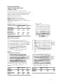
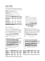
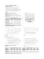
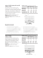
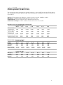
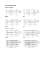
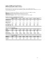
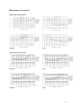
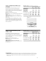
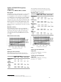
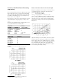
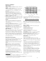
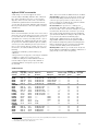
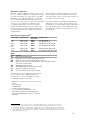
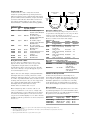
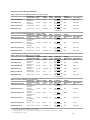
Agilent 8510C
Network Analyzer
8510C
Data Sheet
45 MHz to 110 GHz
Contents
Page
Excellence in
Network Analysis
System performance characteristics . . . . . . . . .3
Major Agilent Technologies 8510 Network
Analyzer Systems
8510E, Option 005, 45 MHz to 20 GHz . . . . . . . . . . . . . .4
8510SX, 45 MHz to 26.5 GHz . . . . . . . . . . . . . . . . . . . . . .5
85107B Option 005, 45 MHz to 50 GHz . . . . . . . . . . . . . .6
85107B Option 005 & 007, 45 MHz to 50 GHz . . . . . . . .7
85106D millimeter-wave systems,
33 GHz to 110 GHz . . . . . . . . . . . . . . . . . . . . . . . . . . . . . . .7
8510XF, E7340A Option 005,
45 MHz to 85 GHz . . . . . . . . . . . . . . . . . . . . . . . . . . . . . . .8
8510XF, E7350A Option 005,
45 MHz to 110 GHz . . . . . . . . . . . . . . . . . . . . . . . . . . . . .10
85108A pulsed-RF system, 2 GHz to 20 GHz . . . . . . . .12
85108L pulsed-RF system, 45 MHz to 2 GHz . . . . . . . .12
8511A, 8511B frequency converters . . . . . . . . . . . . . .13
Accuracy considerations
when using RAMP sweep . . . . . . . . . . . . . . . . . . . . .14
8510C network analyzer capabilities . . . . . . . . . . . . . . .15
8510 System software . . . . . . . . . . . . . . . . . . . . . . . . . . .21
S-Parameter test sets, with common options . . . . . .22
8510C Accessories
(calibration kits, verification kits, and cables) . . . . . . . .23
The 8510C vector network analyzer continues
to provide the best performance to meet your new design
and test challenges. With unmatched accuracy and
convenience, the 8510C vector network analyzer makes
broadband measurements from 45 MHz to 50 GHz in 2.4
mm coax, from 45 MHz to 110 GHz in 1.0 mm coax and
from 33 GHz to 110 GHz in waveguide bands.
The 8510C network analyzer measures the magnitude,
phase, and group delay of two-port networks to characterize their linear behavior. Optionally, the 8510C
network analyzer is also capable of displaying a network’s
time domain response to an impulse or a step waveform
by computing the inverse Fourier transform of the
frequency domain response.
The 8510C family of systems is modular. Choose the
source(s), S-parameter test set(s), and test accessories to
meet your measurement applications. This data sheet
presents performance specifications for most standard
8510 network analyzer systems. To acquire specifications
for system configurations not covered in this data sheet,
refer to the 8510 Specifications and Performance
Verification Software (part number 08510-10033) which
is shipped with all 8510C network analyzers, test sets, and
calibration kits.
2
System performance characteristics
This data sheet offers two types of performance numbers
to describe the merit of any measurement system:
specifications and supplemental characteristics.
Specifications describe the instrument’s warranted
performance over the temperature range of 23 ˚C ± 3 ˚C.
Supplemental characteristics are typical but non-warranted performance parameters. These are denoted as
“typical,” “nominal,” or “approximate.”
To specify the performance of an 8510 system, the data
sheet lists each system’s dynamic range, measurement
uncertainty and measurement port characteristics. The
glossary below explains the major terms used in the
System Performance section of this data sheet.
DYNAMIC RANGE has two descriptions: receiver
dynamic range and system dynamic range. In either case,
the noise floor (which affects Pmin as defined below) is
measured with full two-port error-correction and 1024
averages.
System dynamic range = Pref –Pmin, where Pref is the
nominal or reference power out of port 1 with maximum
power delivered from the source and Pmin is the minimum
power into port 2 that can be measured above the peaks of
the system’s noise floor (10 dB above the average noise
floor). System dynamic range is the amount of attenuation
that can be measured from a 0 dB reference.
Receiver dynamic range = Pmax –Pmin, where Pmax is
the maximum power that can be input to port 2 before
0.1 dB compression of the test set and Pmin is the minimum power into port 2 that can be measured above the
peaks of the system’s noise floor (10 dB above the average noise floor). Receiver dynamic range is the system’s
full usable dynamic range if the system is considered a
receiver. An active device, such as an amplifier, may be
required to realize the receiver dynamic range.
Calibration is the process of measuring standards which
have fully defined models (and are thus called “known”
standards) in order to quantify a network analyzer’s
systematic errors based on an error model.
Calibration must be performed within the operating temperature specified for the calibration kit. For all calibration kits the operating temperature is 23˚ C ±3˚ C. For a
calibration to remain fully verifiable, the temperature of
the network analyzer must remain within ±1˚ C around the
initial measurement calibration temperature.
Error correction is the process of mathematically
removing from the measurement those systematic errors
determined by calibration.
MEASUREMENT UNCERTAINTY curves show the
worst case uncertainty in reflection and transmission
measurements using full two-port error correction with a
specified calibration kit. This includes residual systematic
errors, as well as system dynamic accuracy, connector
repeatability, noise and detector errors. Cable stability and
system drift are not included. All measurements assume
step sweep mode with 1024 averages unless otherwise
specified.
Furthermore, the graphs for reflection measurement
uncertainty apply to a one-port device. The graphs for
transmission measurement uncertainty assume a wellmatched device (S11= S22 = 0). In the phase uncertainty
curves, the phase detector accuracy is better than 0.02
degrees, useful for measurements where only phase
changes.
Using the 8510 specification and performance verification
software, uncertainty curves can be calculated for nonidealized devices, and specifications can be edited
for custom setups.
MEASUREMENT PORT CHARACTERISTICS indicate the RF performance of test set port leakages, mismatches, and frequency response. The specification for
the test set’s crosstalk does not include noise.
“Raw” port characteristics refer to the test set’s intrinsic,
uncorrected performance. “Residual” port characteristics give the test set’s performance after error correction.
3
System performance
Agilent 8510E Option 005
45 MHz to 20 GHz
The following specifications describe the system
performance for the 8510C network analyzer in the 8510E
Option 005 (replaces 85052D fixed loads with 85052B
sliding loads calibration kit) configuration. The system
hardware includes the following:
Test set: 8514B S-parameter test set
RF source: 83621B synthesized sweeper
Calibration kit: 85052B 3.5mm calibration kit
Calibration technique: Full two-port calibration with
sliding loads.
Dynamic range (for transmission measurements)
Maximum power
measured at port 2
Reference power
at port 1 (nominal)
Minimum power
measured at port 2
Receiver dynamic range
System dynamic range
Frequency range (GHz)
0.045–2
2–8
8–20
+20 dBm
+11 dBm
+10 dBm
+2 dBm
–2 dBm
–6 dBm
–66 dBm
86 dB
68 dB
–95 dBm
106 dB
93 dB
–95 dBm
105 dB
89 dB
Measurement uncertainty
System dynamic range
Reflection measurements
Magnitude
Phase
Transmission measurements
Magnitude
RESIDUAL
Directivity
Source match
Load match
Reflection tracking
Transmission tracking
Crosstalk
Phase
Frequency range (GHz)
0.045–2
2–8
48 dB
44 dB
40 dB
33 dB
48 dB
44 dB
±0.003 dB
±0.003 dB
±0.017 dB
±0.044 dB
89 dB
115 dB
8–20
44 dB
31 dB
44 dB
±0.006 dB
±0.084 dB
110 dB
RAW (Typical)
Directivity
Source match
Load match
Frequency range (GHz)
0.045–2
2–8
23 dB
23 dB
17 dB
15 dB
17 dB
15 dB
8–20
14 dB
11 dB
11 dB
4
Agilent 8510SX
45 MHz to 26.5 GHz
The following specifications describe the system performance for the 8510C network analyzer with the 8510SX
configuration. The system hardware includes the following:
Test set: 8515A S-parameter test set
RF source: 83631B synthesized sweeper
Calibration kit: 85052C 3.5mm precision
calibration kit
Calibration technique: TRL two-port calibration
Dynamic range (for transmission measurements)
Frequency range (GHz)
0.045–2
2–8
8–20
Maximum power
measured at port 2
+2 dBm
Reference power
at port 1 (nominal)
–5 dBm
Minimum power
measured at port 2
–98 dBm
Receiver dynamic range 100 dB
System dynamic range
93 dB
20–26.5
+3 dBm
+3 dBm –1 dBm
–9 dBm
–14 dBm –25 dBm
–98 dBm –100 dBm –99 dBm
101 dB
103 dB
98 dB
89 dB
86 dB
74 dB
Measurement uncertainty
System dynamic range
Reflection measurements
Magnitude
Phase
Transmission measurements
Measurement
port character-
Magnitude
Phase
istics
RESIDUAL
Directivity
Source match
Load match
Reflection tracking
Transmission tracking
Crosstalk
Frequency range (GHz)
0.045–2
2–8
48 dB
50 dB
40 dB
50 dB
48 dB
50 dB
±0.003 dB ±0 dB
±0.009 dB ±0.004 dB
114 dB
111 dB
8–20
50 dB
50 dB
50 dB
±0 dB
±0.009 dB
106 dB
20–26.5
50 dB
50 dB
50 dB
±0 dB
±0.01 dB
95 dB
RAW (Typical)
Directivity
Source match
Load match
Frequency range (GHz)
0.045–2
2–8
24 dB
24 dB
23 dB
23 dB
23 dB
23 dB
8–20
28 dB
16 dB
16 dB
20–26.5
27 dB
14 dB
14 dB
5
Agilent 85107B Option 005
45 MHz to 50 GHz
The following specifications describe the system
performance for the 8510C network analyzer in
the 85107B Option 005 (adds step attenuators and bias
tees to the 8517B test set) configuration for 50 GHz measurements. The system hardware includes the
following:
Test set: 8517B S-parameter test set
RF source: 83651B synthesized sweeper
Calibration kit: 85056A 2.4mm calibration kit
Calibration technique: Full two-port calibration with
sliding loads
Dynamic range (for transmission measurements)
Frequency range (GHz)
0.045–2
2–20
20–40
Maximum power
measured at port 2
+17 dBm
Reference power
at port 1 (nominal)
+1 dBm
Minimum power
measured at port 2
–76 dBm
Receiver dynamic range 93 dB
System dynamic range 77 dB
+8 dBm
+4 dBm
40–50
–3 dBm
–8 dBm –19 dBm –30 dBm
System dynamic range
–97 dBm –91 dBm –90 dBm
105 dB
95 dB
87 dB
89 dB
72 dB
60 dB
Measurement uncertainty
Magnitude
Phase
Reflection measurements
Measurement port characteristics
Magnitude
RESIDUAL
Directivity
Source match
Load match
Reflection tracking
Transmission tracking
Crosstalk
Phase
Frequency range (GHz)
0.045–2
2–20
42 dB
42 dB
41 dB
38 dB
42 dB
42 dB
±0.001 dB ±0.008 dB
±0.014 dB ±0.043 dB
99 dB
110 dB
20–40
38 dB
33 dB
38 dB
±0.02 dB
±0.110 dB
93 dB
40–50
36 dB
31 dB
36 dB
±0.027 dB
±0.137 dB
81 dB
RAW (Typical)
Directivity
Source match
Load match
Frequency range (GHz)
0.045–2
2–20
22 dB
18 dB
20 dB
12 dB
20 dB
12 dB
20–40
18 dB
9 dB
9 dB
40–50
18 dB
9 dB
9 dB
6
Agilent 85107B Options 005 and 007
45 MHz to 50 GHz
The following specifications describe the system
performance for the 8510C network analyzer in the
85107B Options 005 (adds step attenuators and bias tees
to the 8517B test set) and 007 (adds high power and high
dynamic range to the 8517B test set) configuration for
50 GHz measurements. Specifications not shown are the
same as those given for the 85107B Option 005. The system hardware includes the following:
Test set: 8517B Option 007 S-parameter test set
RF source: 83651B synthesized sweeper
Calibration kit: 85056A 2.4mm calibration kit
Calibration technique: Full two-port calibration with
sliding loads
Dynamic range (for transmission measurements)
Frequency range (GHz)
0.045–2
2–20
20–40
Maximum power
measured at port 2
+17 dBm
Reference power
at port 1 (nominal)
+5 dBm
Minimum power
measured at port 2
–71 dBm
Receiver dynamic range 88 dB
System dynamic range 76 dB
40–50
+13 dBm
+6 dBm –4 dBm
+2 dBm
–5 dBm –16 dBm
–92 dBm –89 dBm –91 dBm
105 dB
95 dB
87 dB
94 dB
84 dB
75 dB
System dynamic range
Measurement uncertainty
Transmission measurements
Agilent 85106D
33 GHz to 110 GHz
The following specifications describe the system
performance for the 8510C network analyzer in the
85106D configuration for measurements from 33 to
110 GHz in four waveguide bands. For complete
specifications, refer to the 85106D system data sheet.
The system hardware includes the following:
Test set (two each): 85104A series millimeter-wave test
set modules
RF sources (two): 83621B synthesized sweepers
Calibration kit: 11644A series waveguide
calibration kit
Calibration technique: TRL two-port calibration
Dynamic range (for transmission measurements)
Frequency range (GHz)
33–50
40–60
50–75
Maximum power
measured at port 2
+12 dBm +10 dBm
Reference power
at port 1 (nominal)
0 dBm
0 dBm
Minimum power
measured at port 2
–87 dBm –87 dBm
Receiver dynamic range 99 dB
97 dB
System dynamic range 87 dB
87 dB
75–110
+10 dBm
0 dBm
0 dBm
–3 dBm
–75 dBm –79 dBm
85 dB
79 dB
75 dB
76 dB
System dynamic range
7
Agilent 8510XF system performance
E7340A Option 005 (45 MHz to 85 GHz)
The following specifications describe the system performance of the 8510XF system in the E7340A Option
005 configuration, from 0.045 GHz to 85 GHz. The following system configuration was used to generate the
specifications:
Test set: E7342A Option 005, millimeter controller and two test heads, 45 MHz to 85 GHz
RF sources: 83621B and 83651B synthesized sweepers (one each)
Calibration kit: 85059A 1.0 mm precision calibration/verification kit
Calibration techniques: SOLT to 50 GHz, and offset-shorts from 50 to 85 GHz
Dynamic range (for transmission measurements)
Frequency range (GHz)
0.045 - 2
2 - 18
Maximum power (in)
measured at port 2
0 dBm
Reference power (out)
at port 1 (nominal)
0 dBm
Minimum power (in)
measured at port 2
–74 dBm
Receiver dynamic range 74 dB
System dynamic range 74 dB
18 - 40
40 - 50
50 - 65
65 - 75
75 - 85
0 dBm
+10 dBm
+10 dBm
–3 dBm
–3 dBm
–3 dBm
0 dBm
–12 dBm
–12 dBm
–3 dBm
–3 dBm
–10 dBm
–104 dBm
104 dB
104 dB
–84 dBm
94 dB
72 dB
–84 dBm
94 dB
72 dB
–80 dBm
77 dB
77 dB
–80 dBm
77 dB
77 dB
–70 dBm
67 dB
60 dB
Measurement port characteristics
RESIDUAL
Directivity
Source match
Load match
Reflection tracking
Transmission tracking
Frequency range (GHz)
0.045 - 2
2 - 18
30 dB
30 dB
27 dB
27 dB
27 dB
27 dB
±0.10 dB
±0.10 dB
±0.273 dB
±0.273 dB
18 - 40
26 dB
23 dB
23 dB
±0.20 dB
±0.429 dB
40 - 50
24 dB
21 dB
21 dB
±0.25 dB
±0.669 dB
50 - 65
28 dB
28 dB
28 dB
±0.30 dB
±0.322 dB
65 - 75
28 dB
28 dB
28 dB
±0.30 dB
±0.340 dB
75 - 85
28 dB
28 dB
28 dB
±0.30 dB
±0.360 dB
RAW (Typical)
Directivity
Source match
Load match
Frequency range (GHz)
0.045 - 2
2 - 18
20 dB
20 dB
20 dB
20 dB
11 dB
11 dB
18 - 40
15 dB
15 dB
10 dB
40 - 50
15 dB
15 dB
10 dB
50 - 65
13 dB
13 dB
10 dB
65 - 75
10 dB
12 dB
10 dB
75 - 85
10 dB
12 dB
10 dB
8
Measurement uncertainty
Reflection measurements
Magnitude
Phase
Magnitude
Phase
Transmission measurements
Magnitude
Phase
Magnitude
Phase
9
Agilent 8510XF system performance
E7350A Option 005 (45 MHz to 110 GHz)
The following specifications describe the system performance of the 8510XF system in the
E7350A Option 005 configuration, from 0.045 GHz to 110 GHz. The following system configuration was used
to generate the specifications:
Test set: E7352A Option 005, millimeter controller and two test heads, 45 MHz to 110 GHz
RF sources: 83621B and 83651B synthesized sweepers (one each)
Calibration kit: 85059A 1.0 mm precision calibration/verification kit
Calibration techniques: SOLT to 50 GHz, and offset-shorts from 50 to 110 GHz
Dynamic range (for transmission measurements)
Frequency range (GHz)
0.045 - 2
2 - 18
Maximum power (in)
measured at port 2
0 dBm
Reference power (out)
at port 1 (nominal)
0 dBm
Minimum power (in)
measured at port 2
–74 dBm
Receiver dynamic range 74 dB
System dynamic range 74 dB
18 - 40
40 - 50
50 - 75
75 - 85
85 - 100
100 - 110
0 dBm
+10 dBm
+10 dBm
0 dBm
0 dBm
0 dBm
0 dBm
0 dBm
–12 dBm
–12 dBm
–7 dBm
–12 dBm
–12 dBm
–12 dBm
–104 dBm
104 dB
104 dB
–84 dBm
94 dB
72 dB
–84 dBm
94 dB
72 dB
–75 dBm
75 dB
68 dB
–70 dBm
70 dB
58 dB
–70 dBm
70 dB
58 dB
–70 dBm
70 dB
58 dB
Measurement port characteristics
RESIDUAL
Directivity
Source match
Load match
Reflection tracking
Transmission tracking
Frequency range (GHz)
0.045 - 2
2 - 18
30 dB
30 dB
27 dB
27 dB
27 dB
27 dB
±0.10 dB
±0.10 dB
±0.273 dB
±0.273 dB
18 - 40
26 dB
23 dB
23 dB
±0.20 dB
±0.429 dB
40 - 50
24 dB
21 dB
21 dB
±0.25 dB
±0.669 dB
50 - 75
28 dB
28 dB
28 dB
±0.30 dB
±0.322 dB
75 - 85
28 dB
28 dB
28 dB
±0.30 dB
±0.360 dB
85 - 100
26 dB
26 dB
26 dB
±0.30 dB
±0.451 dB
100 - 110
26 dB
26 dB
26 dB
±0.30 dB
±0.451 dB
RAW (Typical)
Directivity
Source match
Load match
Frequency range (GHz)
0.045 - 2
2 - 18
20 dB
20 dB
20 dB
20 dB
11 dB
11 dB
18 - 40
15 dB
15 dB
10 dB
40 - 50
15 dB
15 dB
10 dB
50 - 75
11 dB
11 dB
10 dB
75 - 85
11 dB
11 dB
10 dB
85 - 100
11 dB
11 dB
9 dB
100 - 110
8 dB
10 dB
9 dB
10
Measurement uncertainty
Reflection measurements
Magnitude
Phase
Magnitude
Phase
Transmission measurements
Magnitude
Phase
Magnitude
Phase
11
Agilent 85108A Pulsed-RF System
Dynamic range (for transmission measurements)
Frequency range (GHz)
2–8
8–18
18–20
2 to 20 GHz
The following specifications describe the system
performance for the 8510C network analyzer in
85108A configuration. For complete specifications, refer
to the 85108A system data sheet. The system hardware
includes the following:
Test set: 85110A S-parameter test set
RF sources (one each): 83622B and 83623L synthesized
sweeper
Calibration kit: HP 85052B 3.5 mm calibration kit
Calibration technique: Full two-port calibration with
sliding loads
Maximum power
(measured) at port 21
Reference power
at port 1 (nominal)
Minimum power
(measured) at port 2
(pulsed)
(cw)
Receiver dynamic range (pulsed)
(cw)
System dynamic range (pulsed)
(cw)
+11 dBm +11 dBm
+0 dBm
+11 dBm
–1 dBm
–2 dBm
–64 dBm –63 dBm
–78 dBm –78 dBm
75 dB
74 dB
89 dB
89 dB
64 dB
62 dB
78 dB
77 dB
–62 dBm
–77 dBm
73 dB
88 dB
60 dB
75 dB
Other capabilities such as 50 GHz frequency coverage,
operating within synchronized pulsed bias, and measurements such as spectrum analysis, noise figure and load
pull can be added easily without degradation of the raw
system performance.
System dynamic range (pulsed)
Agilent 85108L Pulsed-RF system
Dynamic range (for transmission measurements)
Frequency range (GHz)
0.045–0.1 0.1–0.5
0.5–2
45 MHz to 2 GHz
The following specifications describe the system
performance for the 8510C network analyzer in
85108L configuration. For complete specifications, refer
to the 85108L system data sheet. The system hardware
includes the following:
Test set: 85110L S-parameter test set
RF sources (two each): 83620B Option H80
synthesized sweeper
Calibration kit: 85050D 7 mm calibration kit
Calibration technique: Full two-port calibration with
broadband loads
1.
2.
Maximum power
(measured) at port 2 2
Reference power
at port 1 (nominal)
Minimum power
(measured) at port 2
(pulsed)
(cw)
Receiver dynamic range (pulsed)
(cw)
System dynamic range (pulsed)
(cw)
+20 dBm
+6 dBm
+5 dBm
+0 dBm
+1 dBm
0 dBm
–53 dBm –66 dBm
–81 dBm –95 dBm
72 dB
72 dB
101 dB
101 dB
53 dB
67 dB
81 dB
95 dB
–66 dBm
–96 dBm
72 dB
100 dB
66 dB
95 dB
This maximum power measurement assumes that the 85110A test set has its internal step attenuators set to 0 dB. The test set can
handle up to 20 W (+43 dBm) of power if the step attenuators are activated and an isolator is installed (in the port 2 rear panel link).
This maximum power measurement assumes that the 85110L test set has its internal step attenuators set to 0 dB. The test set can
handle up to 50 W (+47 dBm) of power if the step attenuators are activated and proper precautions are taken within the open
architecture loops.
12
Agilent 8511A/8511B frequency
converters
The following specifications describe the system
performance for the 8510C network analyzer with
the 8511A/B frequency converter.
45 MHz to 26.5 GHz/45 MHz to 50 GHz
Description
Dynamic range (on all inputs)
Combining the 8511A or 8511B frequency converter with
the 8510C network analyzer results in a four channel
receiver/signal processor operating over a 45 MHz to 26.5
or 50 GHz frequency range. This system offers flexibility
in the configuration of a user-supplied signal separation
network to meet the needs of custom measurements. The
8511A/B contains four separate RF to IF converters all of
which can operate over the entire dynamic range of the
system. Either the a1 or a2 input must be defined as the
reference channel to maintain phase lock and to track the
RF source.
Dynamic accuracy
The following plots show the worst case magnitude
and phase uncertainty due to IF residuals and detector
inaccuracies. These plots exclude uncertainty due to
noise, frequency response, directivity, port matches,
crosstalk, and connector repeatability. Reference power
is –20 dBm.
Frequency range (GHz)
0.045–8
8–20
20–26.5
Maximum power
measured at port 2
8511A
8511B
Reference power
at port 1 (nominal)
8511A
8511B
Minimum power
measured at port 2
8511A
8511B
Receiver
dynamic range
8511A
8511B
System
dynamic range
8511A
8511B
26.5–40
–10 dBm
–9 dBm
–10 dBm –15 dBm ——
——
–8 dBm –12 dBm –12 dBm –17 dBm
–20 dBm
–20 dBm
–20 dBm –20 dBm ——
——
–20 dBm –20 dBm –20 dBm –20 dBm
–112 dBm –115 dBm –113 dBm ——
——
–113 dBm –113 dBm –106 dBm –106 dBm –104 dBm
102 dB
104 dB
105 dB
105 dB
98 dB
94 dB
——
94 dB
——
87 dB
92 dB
93 dB
95 dB
93 dB
93 dB
86 dB
——
86 dB
——
84 dB
Measurement uncertainty
Phase
Magnitude
8511A general information
Input port characteristics
Input ports
Connector type (all inputs): 3.5 mm (f)
Impedance: 50 Ω nominal
The following specifications show the uncorrected
system characteristics at the four measurement ports.
Impedance match
(all four ports)
8511A
8511B
Frequency
response tracking1
8511A
8511B
Crosstalk2
8511A
8511B
1.
2.
8511B general information
Frequency range (GHz)
0.045–8 8–20
20–26.5
26.5–40 40–50
17 dB
17 dB
15 dB
15 dB
9 dB
9 dB
——
9 dB
——
7 dB
±1 dB
±1 dB
±1 dB
±1 dB
±1 dB
±3 dB
——
±3 dB
——
±3 dB
115 dB
116 dB
116 dB
114 dB
114 dB
107 dB
——
——
107 dB 105 dB
40–50
Input ports
Connector type (all inputs): 2.4 mm (f)
Impedance: 50 Ω nominal
Ratio measurement of any two ports, excludes slope.
After error-correction, response and isolation calibration assumes no noise.
13
Accuracy considerations when using
ramp sweep
The uncertainty values for the preceding systems assume
that the microwave source operates in the synthesized
step sweep mode. Selecting ramp sweep saves time; the
8510C allows switching between step and ramp sweep
without the need to recalibrate1.
The frequency accuracy of the 8510 in ramp sweep mode
is determined by the swept frequency accuracy of the
source.
Phase errors due to device electrical length
Ramp sweep adds phase uncertainty to the measurement of
electrically long devices. The phase uncertainty ∆ø is
given by the following equation:
∆ø = (–360/c) x ∆F x L
where c is the propagation velocity in a vacuum
(3 x 1010 cm/sec), ∆F is the frequency accuracy specification of the synthesizer in ramp mode, and L is the electrical length of the device under test. The following graph
shows this uncertainty for the 8360 series synthesizers in
ramp sweep.
For 8360 series synthesizers, the swept frequency accuracy is summarized in the following table:
Sweep width
f ≤26.5 GHz
≤n x 10 MHz
>n x 10 MHz and
≤400 MHz
>400 MHz and
≤4 GHz
>4 GHz
Frequency range
10 MHz to <2 GHz
2 to <7 GHz
7 to <13.5 GHz
13.5 to <20 GHz
20 to <26.5 GHz
26.5 to <38 GHz2
38 to 50 GHz
f >26.5 GHz
≤n x 10 MHz
>n x 10 MHz and
≤800 MHz
>800 MHz and
≤8 GHz
>8 GHz
Accuracy
(% of span, or MHz)
0.1% ± time base accuracy
1%
4 MHz/8 MHz
0.1%
n (Multiplier)
1
1
2
3
4
6
8
Agilent Technologies recommends the 8360 series synthesized sweepers in step sweep mode whenever measuring
phase or group delay of electrically long devices, or whenever the highest system accuracy is required. Ramp sweep
is recommended for measurements of electrically short
devices, or for applications where maximum trace update
rate is desired (for example, tuning).
The plots below indicate the typical swept mode
accuracy.
1.
2.
Ramp sweep mode is not available in the 8510XF systems.
This band is 26.5 to 40 GHz on the 83640A.
14
System capabilities1
Measurement
Ô
Number of display channels: Two display channels are
available.
Number of display parameters: The four basic parameters, S11, S21, S12, S22, can be displayed for either
selected channel in either a “four quadrant” or an “overlay” format.
Measurement parameters: S11, S21, S12, S22.
Parameters may be redefined by the user for special
applications. Conversion to Z1 (input impedance), Z2
(output impedance), Y1 (input admittance), Y2 (output
admittance), and 1/S is also provided.
Domains available: Frequency, time (Option 010), pulse
profile2 (Option 008), auxiliary voltage (rear panel output
acting as device stimulus, range is ±10 VDC), and power3
(sweep power level at a CW frequency).
Formats
Cartesian: log/linear magnitude, phase, group delay,
SWR, real part of complex parameter, imaginary part of
complex parameter.
Smith chart: Marker format can be selected as log magnitude, linear magnitude, R + jX, or G + jB.
Polar: Marker format can be selected as log magnitude,
linear magnitude, phase, or real and imaginary.
Data markers: Five independent data markers read out
and display the value of the formatted parameter and
stimulus (frequency, time, or auxiliary voltage).
Marker functions
Marker search: Specific trace values can be located, such
as MAX, MIN, and target (for example–3.00 dB point)
Discrete/continuous: Markers can indicate data at actual
data points or they can interpolate between data points to
allow the setting of a marker at an exact stimulus value.
Delta marker: Marker readout shows difference between
active marker and the reference marker (any marker can
be used as the reference).
Group delay characteristics
Group delay is computed by measuring the phase change
within a specified step (determined by the frequency
span and the number of points per sweep).
Aperture: Determined by the frequency span, the number of steps per sweep, and the amount of smoothing
applied.
Minimum aperture = (frequency span)/(# points –1)
Maximum aperture = 20% of the frequency span
Range: The maximum delay is limited to measuring
no more than ±180 degrees of phase change within the
minimum aperture.
Range = 1/(2 x minimum aperture)
For example, with a minimum aperture of 200 kHz,
the maximum delay that can be measured is 2.5 µsec.
Accuracy: The following graph shows group delay accuracy at 20 GHz with an 8514B test set and an
83621A operating in stepped sweep mode. Insertion loss
is assumed to be zero.
1.
2.
3.
4.
5.
In general, the following formula can be used to determine the accuracy, in seconds, of a specific group delay
measurement.
0.003 x Phase accuracy (deg) + delay (sec) x linearity (Hz)
Aperture (Hz)
Depending on the aperture and the device length, the
phase accuracy used is either incremental phase accuracy
or worst case phase accuracy. The above graph shows this
transition.
Source control
All source control is provided from the 8510C front panel.
Compatible sources
8360 series synthesized sweeper
8340A/B synthesized sweeper4
8341A/B synthesized sweeper4
8350B sweep oscillator with 835xx RF plug-in4
(ramp sweep mode only)
Sweep limits: Set start/stop or center/span of the stimulus
parameter (frequency, time, or auxiliary voltage).
Measured # points per sweep: Selectable as 51, 101,
201, 401, or 801 points. In frequency list mode, the
number of points can range from 1 to 792.
Sweep modes
Ramp sweep5 (analog)
Stepped sweep (available with all sources except the
Agilent 8350B): A faster version of step sweep, called “quick
step”, is selectable when using an 8360 series synthesized
sweeper.
Frequency list sweep: Define up to 30 different arbitrary
sub-sweep frequency ranges by specifying start/stop,
center/span, or CW sweeps. Define the number of points
or step size for each range. Display all segments or a
single segment on-screen. All frequencies are synthesized
if using the 8340/41 or 8360 series synthesized sweepers.
Frequency domain only.
Single point (single frequency)
Fast CW mode (GPIB only): Raw data (real and imaginary) is sent immediately to GPIB as soon as it is taken.
Display is blanked in this mode. The source is phaselocked once when entering this mode, but is not re-phaselocked at each point. Must be triggered externally (TTL).
Data is available approximately 500 µsec after the trigger
pulse is received.
The symbol Ô denotes a new feature or capability due to the 8510C firmware revision 7.0.
Pulse profile domain is not available in the 8510XF systems.
Power domain requires 8360 series sources. Sources with firmware revisions prior to 01 Oct 93 require updating.
The 8340, 8341 and 8350 series sources are not compatible with the 8510XF systems.
Ramp sweep mode is not available in the 8510XF systems.
15
Ô
Power sweep: From power domain, sweep power at
a CW frequency. When combined with the receiver
calibration feature, power sweep allows quicker and more
accurate absolute-power measurements of an amplifier’s
1 dB gain compression point.
Alternate sweep: The two channels, including markers,
may be coupled1 (same source parameters) or uncoupled
(different source parameters).
Sweep time: Minimum sweep time is automatically
selected, depending on the number of points per sweep
(and the averaging factor if in stepped mode). Longer
sweep times may be entered by the user from 0.1 to
100 seconds.
Source power: Set source power (dBm) or power slope
(dBm/GHz). For the S-parameter test sets with built-in
attenuators, the port 1 or port 2 signal level can be controlled by setting the internal attenuator of the test set.
Flat power is achievable at the test port when using the
user-flatness feature of the 8360 series synthesizers.
An E4418A power meter with the 8480 series of power
sensors are required to measure power for flatness correction.
Multiple frequency control mode: In this mode, the
8510C controls up to three frequency ranges independently: the frequency of the primary source (83621A synthesized sweeper), the frequency of a secondary source
(may be phase-locked 8350B sweep oscillator), and the
frequency of the network analyzer receiver.
Frequency control: All frequency ranges can be separately
defined as functions of the device under test frequency,
by specifying a multiplier (a ratio of integers) and an
offset for each frequency.
Definition storage: The active multiple frequency mode
parameters are stored in non-volatile memory and may be
saved on disc with the hardware configuration.
Sweep modes: All sweep modes can be used in multiple
frequency mode.
External LO phase-lock control: In applications where
an external LO is used in place of a test set, LO phaselock control is provided to phase-lock a sweep oscillator
with DC FM capability (for example, 8350B) to a
synthesized sweeper (for example, 83621A).
Power leveling and power control2
Power leveling capability comes as part of the standard
8510XF systems. With power leveling, power levels at the
test ports are controlled with a typical accuracy of
±1.0 dB with a control range greater than 20 dB.
Power leveling modes: These modes are available in
both RF and LO power control.
System leveling: Power leveled at the test ports and is
entirely controlled by the 8510XF system. This is also the
normal operating mode.
Internal leveling: Power leveled at the output port of the
source.
1.
2.
External leveling: Leveling is achieved using an external
detector.
Leveling off: Source set to the unleveled mode.
Power leveling detections modes: These modes are
available under system leveling. Each mode will determine how the "unleveled" condition is detected.
Always: The 8510C polls for errors during every sweep.
Smart: The 8510C polls for errors during the first sweep
following a change in frequency, and thereafter only if an
error was detected during the first sweep. This is the
default mode.
Once: The 8510C polls for errors only during the first
sweep following a change in frequency.
Never: The 8510C does not poll for errors during any
sweep.
Power control: Set port power (dBm) or power slope
(dBm/GHz). With system leveling selected, the
8510XF system will control the RF source, the
millimeter-wave controller and the test heads to deliver
the user requested power to the test ports.
Vector error correction techniques
Calibration types available: Various calibration types
are available. Once calibrated, the frequency limits may be
narrowed using the FREQUENCY SUBSET feature of the
8510C.
Response/isolation calibration: Compensates for frequency
response and directivity (reflection) or frequency response
and crosstalk (transmission) of test sets. Requires a
short or open circuit and load termination (reflection) or
through connection and load termination (transmission).
One port calibration: Correction of test set port 1 or
port 2 directivity response and source match errors.
Requires three known standards, for example, open,
short, and load (fixed, sliding, or offset) terminations.
Two port calibration: Compensates for port 1 and
port 2 directivity, source match, reflection frequency
response, load match, transmission, frequency response
and crosstalk. Crosstalk (isolation) calibration can be
eliminated.
Full two-port (traditional): For use with an S-parameter
test set, requires three known standards at each port, for
example, short, open (or offset short), and load (fixed,
sliding, or offset) terminations. A through connection is
also required.
One path two-port calibration: A two-port calibration
for one port Reflection/Transmission test sets, such as the
millimeter-wave systems, provides a full two-port errorcorrected measurement when the test device is turned
around and measured in both directions.
In the 8510XF systems, the two channels are coupled (uncoupled channels is not available).
The features or capabilities listed under Power Leveling and Power Control are only available in the 8510XF systems.
16
Ô
Ô
Thru-reflect-line (TRL): A two-port calibration which
requires a through connection, a reflection standard, and
a reference transmission line. S-parameter test sets only.
Line-reflect-match (LRM): A two-port calibration similar
to TRL except it uses fixed loads and not transmission
line(s) as its impedance reference. LRM is a particularly
convenient broadband calibration for non-coaxial environments with accuracy as good as TRL. S-parameter test
sets only.
Adapter removal calibration: A two-port calibration for
noninsertable devices, such as those with identical sexed
connectors on both ports. S-parameter test sets only.
Two-port to one-port calibration: Create and store a
separate one-port calibration set for either port 1 or port
2 from an existing two-port calibration.
Reference plane extension: Redefine the plane of measurement reference (zero phase) to other than that established at calibration. A new reference plane is defined in
seconds of delay from the test set port and ranges
between ±1 second.
Connector compensation: Compensates for errors
between dissimilar but matable connectors such as
3.5 mm and SMA.
Receiver cal: Adjusts non-ratioed receiver inputs to
absolute power levels; displays absolute power in dBm;
requires reference sweep of known source power (using
flatness correction).
Set Zo: Can redefine the characteristic impedance of a
measurement to other than 50 Ω.
Data averaging: Similar to a variable bandwidth IF filter,
this function computes the running average of either a
number of data traces in ramp mode or data points in
stepped mode. Averaging factors range from
1 to 4096 in powers of 2. In stepped sweep mode, each
data point is averaged before being displayed.
Trace smoothing: Similar to variable bandwidth video
filter, this function computes the moving average of adjacent data points in a single trace. Smoothing aperture
ranges from 0.125% to 20% of the trace width.
Data listings: For printing and plotting, the Agilent
8510C can send data, via either its GPIB1 or its RS-232
interface, to the HP ThinkJet, QuietJet, DeskJet,
LaserJet, or PaintJet graphics printers. Measurement
data, operating parameters and system parameters can all
be printed or plotted.
Display control
Display type: Color (raster scan), 7.5” diagonal; display
graticule, 5.5” diagonal.
Title: Add custom titles (49 characters maximum) to the
display of the 8510C. Titles are plotted when making
hardcopies of displayed measurements.
Ô Adjust display: Control the intensity and background
intensity of the display. Also, customize the color, tint,
and brightness of the data traces, memory traces, reference lines, graticules, text, and warning messages. Select
from 16 colors. Default colors can be recalled along with
one set of user-defined display values. Control is in the
percent of full range.
Limit lines: Define up to eight test limit segments per
parameter per channel; segments may be any combination
of flat lines, sloping lines, or discrete points; limit testing
gives pass/fail decision on each sweep.
CRT formats: Single channel, dual channel overlay (both
traces on one graticule), dual channel split (each trace on
separate graticules), four parameter overlay or split.
Trace functions
Display data: Display current measurement data, memory data, or current measurement and memory data
simultaneously.
Trace math: Vector math (+, –, ×, ÷) of current linear
measurement values and memory data.
Scale resolution
Magnitude: Log format (dB/div): 0.001 to 500
Linear format (units/div): 10×10-12 to 500
Phase: Cartesian (degrees/div): 10×10-12 to 500
Polar (degrees/display graticule): 45
Reference value: Ranges between ±500 units (dB, degrees,
seconds, etc.)
Data hardcopy
Reference position: Ranges from the 0 (bottom) to 10
(top) graticule position.
Data plotting: Hard copy plots are automatically
Auto: Automatically selects scale resolution and reference
produced by the 8510C when used with an HP-GL compatible plotter using either the system bus (GPIB compat- value to center the trace on the CRT graticules for easy
viewing.
ible) or serial output interface (RS-232-C).
Electrical delay: Offset measured phase or group delay
Plotter functions: Plot trace(s), graticule(s), marker(s),
data by a defined amount of electrical delay, in seconds.
or text with any plotter pen. Operating and system
Operates similar to an electronic line stretcher. Amount
parameters can also be plotted.
of electrical delay can range between ±1 second. Electrical
Formats: Full or quarter page plots of any parameter.
delay can also be displayed in electrical length (meters)
Plot all 4 S-parameters: Plots all four S-parameters in
or physical length by entering the appropriate VELOCITY
4-quadrant format.
FACTOR, the propagation velocity relative to the speed
Plotter/printer buffer: Retain trace update of the 8510
of light.
while plotting/printing previous data via either of the two
serial output interface (RS-232-C) ports. Total buffer mem- Waveguide delay: Non-linear electrical delay used to
remove the effects of dispersion in waveguide.
ory available is 400 Kbytes for serial output port 1 and
Table delay: Allows user to input an array or real and
100 Kbytes for serial output port 2.
imaginary pairs to correct for dispersion in non-coaxial
media such as microstrip or coplanar waveguide.
1. When printing/plotting from the 8510 system bus (GPIB compatible) port to a Centronics printer/plotter, use
an ITEL-45CHVU or ITEL-45CHVE HP-to-Centronics Converter.
17
Storage
Internal memory
Instrument state: Eight instrument states can be stored
in non-volatile memory via the SAVE menu. They can then
be recalled via the RECALL menu. Instrument states
include all control settings, memory trace data, active list
frequency tables, active calibration coefficients, and custom
display titles. Register 8 is reserved for the power-up state,
which can be defined by the user.
Hardware configurations: One hardware configuration is
stored in active non-volatile memory. This configuration is
not changed at instrument preset. The hardware configuration includes all instrument addresses and the multiple
frequency mode parameters.
Data traces: Eight traces of data can be stored in the
trace memories. Traces 1-4 are stored in non-volatile
memory.
Calibration sets: Eight separate calibration sets may be
stored in non-volatile memory. If any 801-point full twoport calibrations are stored, storage may be limited to as
few as four calibration sets.
Calibration kits: Two calibration kits, including usermodified kits can be stored in the 8510 internally allocated memory. An internally stored kit is written over
when another calibration kit is loaded in the same data
storage location. Calibration kits can also be stored to
disk.
Internal disk drive: The built-in disk drive can be used
to store and retrieve different types of data on a 3.5 inch
disk. Data files can be stored in either the HP LIF or
MS-DOS® formats. Diskettes of double sided format or
high density format are recommended.
External disk drive: Data can also be stored on disk
using an external disk drive with command subset SS/80.
Data files are stored in Hewlett-Packard’s standard LIF
or MS-DOS format.
Disk storage memory requirements
Type of Data to be Stored
Calibration set (full two-port, 801 pts)
Calibration kit
Instrument state
Hardware state
Machine dump
Data data (201 pts)
1 S-parameter
4 S-parameters
Data formatted, raw or memory (201 pts)
User display
Memory Required (Kbytes)
234
2
7
0.5
400
Time stimulus modes
Two types of time domain stimulus waveforms can be simulated during the transformation — a step and an
impulse. Although these waveforms are generated mathematically with the inverse FFT, the results for linear circuits are the same as would be obtained if the actual time
waveforms had been applied and measured.
Low pass step: This stimulus, similar to a traditional
Time Domain Reflectometer (TDR) waveform, is used to
measure low pass devices. Transforming to time low pass
requires a sweep over a harmonic set of frequencies including an extrapolated DC value. The step response is typically used for reflection measurements only. The low pass
step waveform displays a different response for each type
of impedance (R, L, C), giving useful information about the
discontinuities being measured.
Response resolution1: In low pass step mode, response
resolution is determined by the step rise time (10% to
90%) of the time stimulus. This depends on both the
frequency span and the window used (see Windows):
Low pass impulse: This stimulus is also used to
measure low pass devices, and is the mathematical
derivative of the low pass step response. Transforming to
time low pass requires a sweep over a harmonic set of frequencies including an extrapolated DC value. The time
domain response shows changes in the parameter value
versus time. The impulse response can be used for reflection (fault location) or transmission measurements.
Response resolution1: In low pass impulse mode,
response resolution is defined by the 50% impulse width of
the time stimulus. This depends on both the frequency
span and the window used (see Windows):
5.5
20
5.5
33
Time domain (Option 010)
Description
With the time domain option, data from transmission or
reflection measurements is converted from the frequency
domain to the time domain using the inverse Fourier
transform and presented on the CRT display. The time
domain response shows the measured parameter value
versus time. Markers may also be displayed in electrical
length (or physical length if the relative propagation
velocity is entered).
1.
Response resolution is the ability to resolve two closely spaced responses of equal magnitude. For example, in time
impulse response, two equal responses that are separated in time by less than one impulse width cannot be
resolved as two separate responses.
18
Bandpass impulse: The bandpass impulse simulates a
pulsed RF signal (with an impulse envelope) and is used
to measure the time domain response of band-limited
devices. The start and stop frequencies are selectable by
the user to any values within the limits of the source and
test set used. The bandpass time domain response shows
changes in the parameter values versus time. Bandpass
time domain responses are useful for both reflection and
transmission measurements.
Response resolution1: In bandpass impulse mode,
response resolution is defined by the 50% impulse width
of the time stimulus. This depends on both the frequency
span and the window used (see Windows):
Windows: The windowing function can be used to modify
(filter) the frequency domain data to reduce overshoot
and ringing in the Time Domain response. Three types
of windows are available-minimum, normal, maximum.
Typical effective impulse width and sidelobe response
to each type of window are shown in the table below:
Window
type
Minimum
Normal
Maximum
Kaiser
bessel
parameter
0
6
13
Impulse
width
Minimum
1.5x Minimum
2.5x Minimum
Sidelobes
(relative to peak)
–15 dB
–50 dB
–90 dB
Gating: The gating function can be used to isolate
individual Time Domain responses. In converting back to
the frequency domain the effects of the responses outside
the gate are removed. The location and span of the gate
can be controlled by setting either the gate center
position and time span or by setting the gate start and
stop times.
Measurement throughput summary
The following table shows typical measurement times for
an 8510C system with full two-port error correction.
Number of points
51
101
201
Time domain range
The time domain range, the range over which the display
is free of response repetition, depends on the frequency
span and the number of points as shown in the following
graph2:
Measurement3
Ramp sweep4
Stepped sweep
Avg factor = 1
Avg factor = 128
401
801
270 ms 340 ms 470 ms 740 ms 1.3 s
1.25 s
6.25 s
Time domain conversion5 50 ms
GPIB data transfer to computer6
Internal format
20 ms
ASCII format
240 ms
IEEE 754 floating point format
32 bit
20 ms
64 bit
40 ms
2.5 s
12.8 s
5s
24 s
10 s
49 s
20 s
106 s
100 ms 200 ms 400 ms 800 ms
30 ms 50 ms 100 ms 200 ms
460 ms 900 ms 1.8 s
3.6 s
40 ms
80 ms
80 ms 160 ms 320 ms
150 ms 300 ms 590 ms
Remote programming
Range resolution: Range-resolution is the ability to
locate a single response in time. It is a function of the
time span selected and the number of data points. Rangeresolution = time span/(number of points –1). Rangeresolution better than 1 mm (3 ps) can typically be
achieved. This is determined by source stability.
1.
2.
3.
4.
5.
6.
Interface: GPIB interface operates according to IEEE
488-1978 and IEC 625 standards and IEEE 728-1982
recommended practices.
System interface: The 8510C system bus is a GPIB port
used exclusively by the 8510C to control and extract
information from the other instruments in the system
such as the RF source, test set, and the
digital plotter.
Addressing: The GPIB addresses of the 8510C and all
instruments connected to the 8510 system interface can
be verified or set from the 8510C front panel via the
LOCAL menu. Addresses can range from 0 to 30 decimal.
Response resolution is the ability to resolve two closely spaced responses of equal magnitude. For example, in time impulse response, two equal
responses that are separated in time by less than one impulse width cannot be resolved as two separate responses.
In low pass mode (step or impulse), range is limited by the minimum spacing between frequency domain data points (45 MHz, or 22.5 MHz with 801
points). This limit is labeled on the graph as “low pass limit”.
Includes system retrace time, but does not include source bandswitch times (typically 50 msec each). Time domain gating is assumed off.
If averaging is used, multiply the above ramp sweep measurement times by the averaging factor to get the total time.
Option 010 only, gating off.
Measured with an HP 9000 Series 300 computer. Single point data transfers can be accomplished in approximately 1 msec per point using the fast
CW mode.
19
General characteristics
Rear panel connectors
Sweep in: Input for 0 to 10 V sweep voltage from
compatible sweep oscillator.
Stop sweep: Input and output for stop sweep signal from
compatible sweep oscillator.
10 MHz in: Input for external 10 MHz reference.
Input level: –10 dBm to +20 dBm, typical
Input frequency accuracy: ±0.005% (50 ppm)
20 MHz out: Output of internal 20 MHz
reference oscillator.
Frequency accuracy: ±0.01%, typical
Analog ±10V: Settable output voltage used for auxiliary
voltage domain measurements, or analog output for analog recorders.
Range: –9.995 to +10.000 volts
Linearity: ±0.1%, typical
Resolution: 4.88 mV, nominal
Output impedance: 1k Ω
External trigger: TTL input to trigger acquisition of
single data point. Delay is included to equalize the single
path delay from the test port. Data is taken on negativegoing TTL pulse.
Pulse repetition period: 1 msec minimum with no
averaging. If averaging, add (200 µs x averaging factor).
Pulse width: 1 µs minimum.
Environmental
Operating conditions: Temperature: 5 ˚C to 40 ˚C
Non-operating conditions: Temperature: –40 ˚C
to +75 ˚C
Power
47.5 to 66 Hz: 100, 120, 200, 240 Vac, ±10%
8510C: 460 VA, maximum
Test sets: 145 VA, maximum
8510XF millimeter-subsystem: 500 VA, maximum
Weight
8510C: Net, 42 kg (92 lb); shipping, 52 kg (114 lb)
8511A/B: Net, 15 kg (33 lb); shipping, 18 kg (40 lb)
8514B: Net, 17 kg (38 lb); shipping, 20 kg (45 lb)
8515A: Net, 19 kg (41 lb); shipping, 22 kg (48 lb)
8517B: Net, 15.5 kg (34.2 lb); shipping, 18.7 kg (41.2 lb)
85105A: Net, 20.4 kg (45 lb); shipping, 24.5 kg (54 lb)
85104A series modules (each): Net, 6 kg (23 lb);
shipping 6.8 kg (15 lb)
8510XF controller: Net, 20.4 kg (45 lb); shipping,
24.5 kg (54 lb)
8510XF test heads (each): Net, 11.34 kg (25 lb);
shipping, 13.6 kg (30 lb)
Dimensions
(Allow 10 cm, 4 inches
clearance at rear panel
for interconnect cables)
TOP
42.4 cm (16.7 in)
50.8 cm (20 in)
REAR
13.3 cm (5.25 in)
44.5 cm (17.45 in)
The factory selected addresses are the following:
8510C network analyzer
16
Source #1
19
Source #2
18
Test set
20
Plotter
05
Printer
01
Disc drive
00
Pass-through address
17
Pass-through address: Instruments connected to the
8510C system bus may be accessed via the pass-through
address.
Transfer formats:
Binary (internal 48 bit floating point complex format)
ASCII
32/64 bit IEEE 754 floating point format
Form 5 (for transfer to PC’s)
Interface function codes:
SH1, AH1, T6, TE0, L4, LE0, SR1, RL1, PPO, DC1, DT0,
CO, E1
SIDE
20
System Software
Agilent 85161B measurement automation
software
Description: This software is designed specifically to
operate on an HP 9000 Series 200 or 300 computer for
automation of the 8510 system including millimeter-wave
systems. The software complements the hardware, providing calibration, measurement, and data output capabilities
with a minimum of operator interaction. Measurement
data can be stored in binary format or in a data file compatible with many CAE design programs.
Operating requirements
Compatible with an HP 9000 Series 200 or 300 computer
with the following:
BASIC Operating System (5.0 or higher)
RAM memory (including BASIC): 2 Mbytes, or a PC
running Basic for Windows revision 6.3 or higher under
Windows (3.1/95/NT)
Agilent 85070B dielectric probe kit
The 85070B dielectric probe kit allows convenient nondestructive testing of materials using the open-ended coaxial probe method. The probe, together with its own
dedicated software, determines the complex permittivity
of a wide variety of liquids, semi-solids, and solids. Since
the probe kit measures only permittivity, only nonmagnetic materials should be measured. Measurements
are efficient and cost-effective because the testing is
non-destructive and there is no need for sample
preparation or special fixtures. Refer to the 85070B data
sheet for more information.
Agilent 85071B materials measurement
software
Description: The 85071B software takes broad-band Sparameter measurements of dielectric and magnetic materials and determines their electromagnetic properties. The
software calculates both the complex permittivity εr (or
dielectric constant) and permeability µr, including their
loss factors. Depending on the network analyzer and fixtures used, measurements can extend from 100 MHz
to 110 GHz. The software offers the choice of four
algorithms, each designed to address specific
measurement needs.
Operating requirements
Standard: Requires MS-DOS on an HP Vectra (or any
100%-compatible PC-AT computer) compatible with
Microsoft® Windows 2.11 with mouse. Requires >20
Mbyte hard disk and >640 Kbytes RAM.
Option 300: Substitutes BASIC software for the
standard version for operation with the 9000 Series 300
controllers. Requires BASIC 5.0 or higher and 2 Mbytes
of RAM.
Refer to the 85071B data sheet for more information.
21
S-parameter test sets
Description
Combining the 8510C network analyzer with
an 8514B, 8515A, or 8517B results in a system for making
full S-parameter measurements. The dual port architecture of the test sets develops a separate reference channel for each incident port. RF switching is done with a
single built-in electronic switch.
Test set general information
Frequency range (GHz)
Test ports (port 1 or 2)
Nominal operating
power level (dBm)
Connector type
Impedance, DC bias
Attenuation range
(incident signal)
RF input connector
(rear panel)
Max. input power
Connector type
8514B
8515A
8517B
85110A
85110L
85105A/85104A
0.045 to 20
0.045 to 26.5
0.045 to 50
2 to 20
0.045 to 2
33 to 50
40 to 60
50 to 75
75 to 110
2 to –6
–5 to –25
+2 to –29
+5 to –161
3.5 mm (m) 3.5 mm (m)
2.4 mm (m)
50 Ω nominal, 500 mA, 40 Vdc maximum
0 to –3
0
0
0
0
–3
3.5 mm (m)
7 mm
WR-22
WR-19
WR-15
Waveguide impedance, no bias
WR-10
0 to 90 dB, in 10 dB steps
0 to 60 dB, in
10 dB steps
0 to 90 dB, in 10 dB steps
N/A
N/A
N/A
N/A
+16 dBm
3.5 mm (f)
+16 dBm
2.4 mm (f)
+14 dBm
3.5 mm (f)
+13 dBm
3.5 mm (f)
+13 dBm
3.5 mm (f)
+13 dBm
3.5 mm (f)
+13 dBm
3.5 mm (f)
+14 dBm
3.5 mm (f)
+14 dBm
3.5 mm (f)
Ordering information
The following options are available on the test sets:
Option 001: Add IF switching. Allows four test sets with
different addresses to be connected to the 8510 at
the same time. The test set in use is selected from the
8510C front panel. The 20 MHz IF signal is daisychained
from the test sets to the 8510. IF switching
is performed automatically without reconnections.
Option 002: Delete step attenuators and bias tees
(8514B, 8515A, 8517B only). If attenuators are not
required, but bias is required, bias can be applied externally using the 11612A/B bias tees.
1.
Option 003: Forward configuration (8514B only).
Forward coupler configuration; optimization for forward
dynamic range.
Option 004: High power configuration (8517B only).
Optimized for testing of high power devices (up to 1 watt)
by moving the port 2 step attenuator before the b2
sampler.
Option 007: High power and high dynamic range configuration (8517B only). Adds broadband amplifiers at the input,
and before each sampler. Requires 8510C firmware revision 7.0.
8517B Option 007
22
Agilent 8510C accessories
A wide range of accessories support the 8510C
network analyzer including calibration kits, verification
kits, cables and adapters in 7 mm, 3.5 mm, 2.92 mm.
Type-N, 2.4 mm, 1.85 mm and 1.0 mm coax and in the
standard waveguide bands. The standards used in the
3.5 mm, Type-N, and 2.4 mm calibration and verification
kits use precision slotless connectors1 (PSC-3.5, PSC-N,
and PSC-2.4).
Calibration kits
Before a network analyzer can make error-corrected measurements, the network analyzer’s systematic errors must
be measured and removed. Calibration is the process of
quantifying these errors by measuring “known”, or precision standards. The calibration kits listed below contain
the precision mechanical standards required to calibrate
an 8510 system. For calibrating an 8510 system in the 7
mm, 3.5 mm, 2.92 mm, Type-N, 2.4 mm, 1.85 mm, or 1.0
mm interface, mechanical calibration kits all contain the
following:
• Calibration standards to perform full-two port
calibration
• Torque wrenches for properly connecting the standards
• Adapters to change the sex of the test port
• A disk for loading the standard definitions into the
network analyzer. Option 0022 provides calibration
standard definitions on magnetic tape for use with
the 8510A/B.
Three classes of mechanical calibration kits are available:
Standard kits contain open circuits, short circuits, and
both fixed and sliding terminations in both sexes for all
connector types (except 7 mm, a sexless connector).
Connector gauges are included in these kits for maintaining each standard’s connector interface.
Precision kits have precision 50 Ω airline(s) for
performing the Thru-Reflect-Line (TRL) calibration2,
the most accurate error-correction technique for coaxial
measurements. These kits also contain the open circuit,
short circuit, and fixed terminations used for traditional
open-short-load calibration techniques. All precision kits
except the 85052C and 85059A include gauges.
All waveguide calibration kits are precision kits and
support TRL calibration in their waveguide band. Most
kits contain two straight waveguide sections with precision
flanges, a flush short circuit, a precision waveguide line
section, and either sliding or fixed terminations.
Economy kits include the open circuit, short circuit, and
fixed termination standards but not sliding terminations or
gauges. Gauges can be ordered separately.
Calibration kits
Cal kit type
and name
STANDARD
85050B
85052B
85054B
85056A
PRECISION
85050C
85052C
85059A
X11644A1
P11644A1
K11644A1
R11644A
Q11644A
U11644A
V11644A
W11644A
ECONOMY
85050D
85052D
85054D
85056D
1.
2.
Frequency
range (GHz)
fmin–fmax
Connector
type
Return loss,
fixed load
Return loss,
sliding load
Residual
Return loss (dB), directivity (dB)
airline @ fmax
@ fmax
Residual source
match (dB)
@ fmax
0.045–18
0.045–26.5
0.045–18
0.045–50
7 mm
3.5 mm
Type-N
2.4 mm
≥52 dB, DC–2 GHz
≥44 dB, DC–3 GHz
≥48 dB, DC–2 GHz
≥42 dB, DC–4 GHz
≥ 52 dB, 2–18 GHz
≥44 dB, 3–26.5 GHz
≥42 dB, 2–18 GHz
≥36 dB @ 50 GHz
––––
––––
––––
––––
52
44
42
36
41
31
32
32
0.045–18
0.045–26.5
0.045–110
8.2–12.4
12.4–18
18–26.5
26.5–40
33–50
40–60
50–75
75–110
7 mm
3.5 mm
1.0 mm
WR-90
WR-62
WR-42
WR-28
WR-22
WR-19
WR-15
WR-10
≥38 dB, DC–18 GHz
≥46 dB, DC–2 GHz
≥24 dB, DC–50 GHz
≥42 dB, 8.2–12.4 GHz
≥42 dB, 12.4–18 GHz
≥42 dB, 18–26.5 GHz
––––
––––
––––
≥38 dB
≥36 dB
––––
––––
––––
––––
––––
––––
≥46 dB
≥46 dB
≥46 dB
––––
––––
>60
50
––––
50
50
50
50
50
50
50
50
60
50
24
50
50
50
50
50
50
50
46
60
50
21
50
50
50
50
50
50
50
46
0.045–18
0.045–26.5
0.045–18
0.045–50
7 mm
3.5 mm
Type-N
2.4 mm
≥38 dB, DC–18 GHz
≥30 dB @ 26.5 GHz
≥34 dB @ 18 GHz
≥26 dB @ 50 GHz
––––
––––
––––
––––
––––
––––
––––
––––
40
30
34
26
35
25
28
23
Precision slotless connectors provide greater accuracy and repeatability than standard connectors because the
impedance does not change when it is connected to a device.
Not available with the 85059A calibration kit
23
Electronic calibration
Electronic calibration (ECal) is a precision, single connection, one- or two-port calibration technique that uses fully
traceable and verifiable electronic impedance standards.
ECal replaces the traditional calibration technique that
uses mechanical standards. ECal requires fewer connections. It removes the intensive operator interaction, which
is prone to errors. A full two-port calibration can be
accomplished with a single connection of the ECal
module and minimal operator interaction. This results
in a faster and more repeatable calibration. Calibrations
for non-insertable devices are equally convenient and
straight forward.
ECal modules are controlled manually or automatically
via the 85097A PC interface module with control software. The 85097A consists of a PC interface module, control software and a power supply.
The Agilent 85090 family of RF ECal modules provides
calibration across the complete frequency range of the
8753C/D/E vector network analyzers. The 85060 family of
microwave ECal modules provides calibrations through
26.5 GHz for the 8510B/C and 8719/20/22C/D vector network analyzers.
ECal modules and available optionsA, B
Connector type1
Frequency range
7 mm
7 mm
Type-N
Type-N
UK6
3.5 mm
3.5 mm
30 kHz to 6 GHz2
1 GHz to 18 GHz
30 kHz to 6 GHz2
1 GHz to 18 GHz
ECal module
model number
85091A
85060B
85092A
85064B
Available options
1BN, 1BP, 910, UK6
001, 1BN, 1BP, 910, UK6
00F, 00M, 00A, 1BN, 1BP, 910, UK6
001, 00F, 00M, 00A, 1BN, 1BP, 910,
30 kHz to 6 GHz2
1 GHz to 26.5 GHz
85093A
85062B
00F, 00M, 00A, 1BN, 1BP, 910, UK6
001,00F, 00M, 00A, 1BN, 1BP, 910, UK6
Options
Option
001
00F
00M
00A
1BN
1BP
910
UK6
Description
Adds a 30 kHz to 6 GHz RF module2
Replace f/m connectors on ECal module(s) with f/f connectors
Replace f/m connectors on ECal module(s) with m/m connectors
Adds male-to-male and female-to-female adapters (also adds a 5/16” 90 N-cm (8 in-lb)
torque wrench to 3.5 mm modules)
Mil-STD 45662 calibration certificate
Mil-STD 45662 calibration certificate with measured data
Add an extra operating and service manual
Commercial calibration certificate with measured data
An 85097A PC interface module with control software
must be ordered to drive all ECal modules. The
85097A requires a customer-supplied PC meeting
the following minimum requirements:
• Windows 95®, Windows NT 4.0® or later operating
system
• 486 or later CPU
• 32 MB of RAM
• 10 MB available hard-disk space
• one of the following GPIB interface cards:
82340A/B, 82341C/D, National AT-GPIB/TNT,
National AT-GPIB/TNT (plug&play) or National
PCI-GPIB
1. For ECal modules with sexed (m-f) connectors, the standard modules have one female and one male connector.
2. RF ECal modules are specified to operate from 300 kHz to 6 GHz, with typical performance down to 30 kHz.
A. 85060 series modules cover a frequency range of 1 GHz to either 18 or 26.5 GHz. The upper frequency is limited by
the connector cutoff frequency. Each module is supplied with a torque wrench and foam-padded wood storage box.
B. 85090 series modules cover a frequency range of 30 kHz to 6 GHz. Each module is supplied with a torque wrench and
foam-padded wood storage box.
24
Verification kits
Verification kits are used to verify that a network
analyzer is operating within its specified performance.
Agilent Technologies offers verification kits that include
precision airlines, mismatch airlines, and precision fixed
attenuators. All verification kits include measurement
data and uncertainties which are traceable to the U.S.
National Institute of Standards and Technology (NIST).
Network analyzer
test set
Device
under
test
Network analyzer
test set
Test port
adapter
Cable set
Device
under
test
Single cable
Verification kits
Verification
kit
85051B
85053B
85055A
85057B
R11645A
Q11645A
U11645A
V11645A
W11645A
Connector Frequency Description
type
range (GHz) (Contents)
7 mm
0.045–18
10 cm airline, stepped
impedance airline, 20 dB, and
50 dB attenuators
3.5 mm
0.045–26.5 7.5 cm airline, stepped
impedance airline 20 dB, and
40 dB attenuators
Type-N
0.045–18
10 cm airline, stepped
impedance airline, 20 dB and
50 dB attenuators
2.4 mm
0.045–50
50 Ω airline, stepped
impedance airline, 20 dB and
40 dB attenuators
WR-28
26.5–40
All contain:
WR-22
33–50
Standard waveguide section
WR-19
40–60
Standard waveguide
mismatch
WR-15
50–75
20 dB attenuator
WR-10
75–110
50 dB attenuator
Test port return cables
Test port cables are available in the 7 mm, 3.5 mm,
Type-N, 2.4 mm, and 1.0 mm connector types1. The
configurations and performance for all cables are
described in the tables on the opposite page. All cable
ends connect directly to the special rugged test port of
the network analyzer test set.
Agilent offers two cable designs: semi-rigid and flexible.
Semi-rigid cables offer excellent performance and are
suitable for applications where the connectors of the DUT
are “in-line” or parallel. Flexible cables are ideal for manufacturing environments since they are more rugged and
have a tighter bending radius than semi-rigid cables.
Semi-rigid cables are warranted for 90 days;
flexible cables are warranted for one year.
Test port adapter sets
The 85130 series test port adapter sets protect the test
set port when connecting devices to the test port. These
adapters convert the rugged test set port to a
connection that can be mated with the device under test.
Each set contains a male and a female adapter.
Adapter sets
Adapter
set
85130C
85130D
85130E
85130F
85130G
11904S
Connector type
(test port to device)
3.5 mm2 to Type-N
3.5 mm2 to PSC-3.5 mm (f)
or 3.5 mm (m)
2.4 mm2 to 7 mm
2.4 mm2 to PSC-3.5 mm (f)
or 3.5 mm (m)
2.4 mm2 to PSC-2.4 mm (f)
or 2.4 mm (m)
2.4 mm2 to 2.92 mm (4)
Frequency
Return loss
(DC–fmax)
(dB) @ fmax
DC–18 GHz
≥28
DC–26.5 GHz ≥28
DC–18 GHz
DC–26.5 GHz
≥26
≥26
DC–50 GHz
≥23
DC–40 GHz
≥28
Waveguide to 1.0 mm adapter kits
Adapter kit
V85104A K10
W85104A K10
Frequency range Description (contents)
DC–75 GHz
WR-15 to 1.0 mm (f)
adapters (4) and 1.0 mm
coax cables (2)
DC–110 GHz
WR-10 to 1.0 mm (f)
adapters (4) and 1.0 mm
coax cables (2)
85043C racked system kit
85043C racked system kit is a rack standing 132 cm
(52 in) high, with a width of 60 cm (23.6 in), and a depth
of 80 cm (32 in). Complete with support rails and AC power
distribution (suitable for 50 to 60 Hz, 100 to 240 VAC),
the kit includes rack mounting hardware for all instruments. Thermal design is such that no rack fan is needed.
Bias networks
Either a single long cable or a shorter cable set can
connect a coaxial device to the test set. A single cable
with an appropriate test port adapter is best for applications where the DUT requires a connection next to the
test port for mechanical rigidity. A set of cables offers the
flexibility required to position the test devices away from
the test set.
1.
2.
3.
The 11612 bias networks apply DC as close to the device
as possible, bypassing the test set's internal shunt resistor.
These bias networks are especially useful when measuring
DC parameters of semiconductor devices.
Model number
11612A K10/K203
11612A K12/K223
11612B K11/K213
Frequency range
45 MHz–26.5 GHz
400 MHz–26.5 GHz
45 MHz–50 GHz
Maximum
current
0.5 amps
2.0 amps
0.5 amps
Maximum
voltage
40 volts
40 volts
40 volts
To measure Type-N devices, use a pair of 7 mm cables and the 7 mm-to-Type-N adapters provided in the
85054B, D calibration kits.
Special rugged female connector specifically for connecting to the network analyzer test port, but does not mate
with a standard male connector
Special option number K1x refers to port 1, K2x refers to port 2
25
Test port return cable specifications
Single cables for the 8514B and 8515A test sets (3.5 mm)
Frequency
(GHz)
DC–26.5
Length2
cm (inch)
81 (32)
Return
loss (dB)
≥17
DC–26.5
96.5 (38)
≥16
85132C semi-rigid cable
Connector type
(test port to device)
3.5 mm3 to
PSC-3.5 mm (f)
3.5 mm3 to
PSC-3.5 mm (f)
3.5 mm3 to 7 mm
DC–18
81 (32)
≥17
85132E flexible cable
3.5 mm3 to 7 mm
DC–18
97.2 (38.25) ≥17
85131C semi-rigid cable
85131E flexible cable
Insertion loss
(dB) (f in GHz)
0.43 √f +0.3
(2.5 dB @ fmax)
0.35 √f +0.3
(2.1 dB @ fmax)
0.35 √f +0.3
(1.8 dB @ fmax)
0.35 √f +0.3
(1.8 dB @ fmax)
Stability1, 2
±magnitude (dB)
<0.06
±Phase (degrees)
0.16 (f) +0.5
<0.22
0.16 (f) +0.8
<0.06
0.16 (f) +0.5
<0.22
0.16 (f) +0.8
Cable set for the 8514B and 8515A test sets (3.5 mm)
Frequency
(GHz)
DC–26.5
Length2
cm (inch)
53 (21)
Return
loss (dB)
≥16
Insertion loss
(dB) (f in GHz)
0.30 √f +0.2
(1.8 dB @ fmax)
Stability1, 2
±magnitude (dB)
<0.06
±Phase (degrees)
0.16 (f) +0.5
DC–26.5
62.2 (24.5)
≥16
0.25 √f +0.2
(1.5 dB @ fmax)
<0.12
0.13 (f) +0.5
85132D semi-rigid cable set
Connector type
(test port to device)
3.5 mm3 to
PSC-3.5 mm (f) or
3.5 mm (m)
3.5 mm3 to
PSC-3.5 mm (f) or
3.5 mm (m)
3.5 mm3 to 7 mm
DC–18
53 (21)
≥17
<0.06
0.16 (f) +0.5
85132F flexible cable set
3.5 mm3 to 7 mm
DC–18
62.9 (24.75) ≥17
0.25 √f +0.2
(1.3 dB @ fmax)
0.25 √f +0.2
(1.3 dB @ fmax)
<0.12
0.13 (f) +0.5
Insertion loss
(dB) (f in GHz)
0.84 √f +0.3
(5.6 dB @ fmax)
0.58 √f +0.35
(4.45 dB @ fmax)
0.46 √ f +0.3
(2.7 dB @ fmax)
0.46 √ f +0.3
(2.7 dB @ fmax)
0.46 √ f +0.3
(2.25 dB @ fmax)
0.46 √ f +0.3
(2.25 dB @ fmax)
Stability1, 2
±magnitude (dB)
<0.06
±Phase (degrees)
0.18 (f)
<0.25
0.8 +0.16 (f)
<0.06
0.18 (f)
<0.22
0.16 (f) +0.8
<0.06
0.18 (f)
<0.22
0.16 (f) +0.8
85131D semi-rigid cable set
85131F flexible cable set
Single cables for the 8517B test set (2.4 mm)
Frequency
(GHz)
DC–50
Length2
cm (inch)
81 (32)
Return
loss (dB)
≥15
DC–50
113 (44)
≥12.5
DC–26.5
81 (32)
≥16
DC–26.5
97.2 (38.25) ≥16
85135C semi-rigid cable
Connector type
(test port to device)
2.4 mm3 to
PSC-2.4 mm (f)
2.4 mm3 to
PSC-2.4 mm (f)
2.4 mm3 to
PSC-3.5 mm (f)
2.4 mm3 to
PSC-3.5 mm (f)
2.4 mm3 to 7 mm
DC–18
81 (32)
85135E flexible cable
2.4 mm3 to 7 mm
DC–18
97.2 (38.25) ≥17
85133C semi-rigid cable
85133E flexible cable
85134C semi-rigid cable
85134E flexible cable
≥17
Cable set for the 8517B test set (2.4 mm)
Frequency
(GHz)
DC–50
Length2
cm (inch)
53 (21)
Return
loss (dB)
≥15
Insertion loss
(dB) (f in GHz)
0.55 √f +0.2
(3.7 dB @ fmax)
Stability1, 2
±magnitude (dB)
<0.06
±Phase (degrees)
0.16 (f)
DC–50
72 (28)
≥12.5
0.48 √f +0.25
(3.64 dB @ fmax)
<0.17
0.8 +0.16 (f)
DC–26.5
53 (21)
≥16
0.31 √ f+0.2
(1.8 dB @ fmax)
<0.06
0.18 (f)
DC–26.5
62.9 (24.75) ≥16
0.31 √ f+0.2
(1.8 dB @ fmax)
<0.12
0.13 (f) +0.5
85135D semi-rigid cable set
Connector type
(test port to device)
2.4 mm3 to
PSC-2.4 mm (f) or
2.4 mm (m)
2.4 mm3 to
PSC-2.4 mm (f) or
2.4 mm (m)
2.4 mm3 to
PSC-3.5 mm (f) or
3.5 mm (m)
2.4 mm3 to
PSC-3.5 mm (f) or
3.5 mm (m)
2.4 mm3 to 7 mm
DC–18
53 (21)
≥17
<0.06
0.18 (f)
85135F flexible cable set
2.4 mm3 to 7 mm
DC–18
62.9 (24.75) ≥17
0.31 √ f+0.2
(1.5 dB @ fmax)
0.31 √ f+0.2
(1.5 dB @ fmax)
<0.12
0.13 (f) +0.5
85133D semi-rigid cable set
85133F flexible cable set
85134D semi-rigid cable set
85134F flexible cable set
1.
2.
3.
Phase stability of semi-rigid/flexible cables is specified with a 90 degree bend and a 4" radius.
Cable length and stability are supplemental characteristics.
Special rugged female connector specifically for connecting to the network analyzer test port, but does not mate
with a standard male connector.
26
Related literature
Agilent 8510 Network Analyzer Color Brochure
Agilent 8510 System Solutions
Agilent 8510 Family Network Analyzer Configuration Guide
Agilent 85103 Upgrade Package to the 8510
Agilent 85106D Millimeter-wave Network Analyzer System
Product Overview
5091-8965E Agilent 85108A/L CW/Pulsed Network Analyzer Systems
Product Overview
5965-9888E Agilent 8510XF 110 GHz Single-Sweep Systems
Product Overview
5963-3743E Agilent 85060 Series and 85090 Series Electronic Calibration
Modules and PC Interface
5091-8970E
5965-8837E
5091-8967E
5091-8969E
5964-4229E
MS-DOS® is U.S. registered trademark of Microsoft Corporation.
Microsoft® is a U.S. registered trademark of Microsoft Corporation.
Windows® and MS Windows® are U.S. registered trademarks of Microsoft Corporation.
27
Agilent Technologies’ Test and Measurement
Support, Services, and Assistance
Agilent Technologies aims to maximize the value you receive, while
minimizing your risk and problems. We strive to ensure that you
get the test and measurement capabilities you paid
for and obtain the support you need. Our extensive support
resources and services can help you choose the right Agilent products for your applications and apply them successfully. Every
instrument and system we sell has a global warranty. Support is
available for at least five years beyond the production life of the
product. Two concepts underlie Agilent’s
overall support policy: “Our Promise” and “Your Advantage.”
By internet, phone, or fax, get assistance with all your test and
measurement needs.
Online Assistance
www.agilent.com/find/assist
Phone or Fax
United States:
(tel) 1 800 452 4844
Canada:
(tel) 1 877 894 4414
(fax) (905) 206 4120
Our Promise
“Our Promise” means your Agilent test and measurement equipment will meet its advertised performance and functionality. When
you are choosing new equipment, we will help you with product
information, including realistic performance specifications and
practical recommendations from experienced test engineers. When
you use Agilent equipment, we can verify that it works properly,
help with product operation, and provide basic measurement assistance for the use of specified capabilities, at no extra cost upon
request. Many self-help tools are available.
Europe:
(tel) (31 20) 547 2323
(fax) (31 20) 547 2390
Your Advantage
“Your Advantage” means that Agilent offers a wide range of
additional expert test and measurement services, which you
can purchase according to your unique technical and business
needs. Solve problems efficiently and gain a competitive edge
by contracting with us for calibration, extra-cost upgrades, out-ofwarranty repairs, and on-site education and training, as well
as design, system integration, project management, and other professional services. Experienced Agilent engineers and tech-nicians
worldwide can help you maximize your productivity, optimize the
return on investment of your Agilent instruments and systems, and
obtain dependable measurement accuracy
for the life of those products.
Australia:
(tel) 1 800 629 485
(fax) (61 3) 9272 0749
Japan:
(tel) (81) 426 56 7832
(fax) (81) 426 56 7840
Latin America:
(tel) (305) 269 7500
(fax) (305) 269 7599
New Zealand:
(tel) 0 800 738 378
(fax) (64 4) 495 8950
Asia Pacific:
(tel) (852) 3197 7777
(fax) (852) 2506 9284
Product specifications and descriptions in this
document subject to change without notice.
Copyright © 1999, 2000 Agilent Technologies
Printed in U.S.A. 6/00
5091-8484E