1
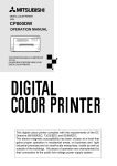
COLOUR VIDEO COPY PROCESSOR
MODEL
CP910E
OPERATION MANUAL
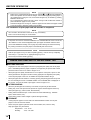
ALARM
SHEET
PAPER
S-VIDEO
THIS OPERATION MANUAL IS IMPORTANT
TO YOU.
PLEASE READ IT BEFORE USING YOUR
COLOUR VIDEO COPY PROCESSOR.
This video copy processor complies with the requirements of the EC Directive
89/336/EEC, 73/23/EEC, 93/42/EEC and 93/68/EEC.
The electro-magnetic susceptibility has been chosen at a level that gains proper
operation in residential areas, on business and light industrial premises and on
small-scale enterprises, inside as well as outside of the buildings. All places of
operation are characterised by their connection to the public low voltage power
supply system.
CONTENTS
Contents ................................................................................................
Safety precautions ................................................................................
Special features ....................................................................................
Unpacking .............................................................................................
Features and functions .........................................................................
2
3-5
6
7
8-10
Front panel ............................................................................................. 8
Rear panel ............................................................................................. 9
Remote control unit ................................................................................ 10
Connections .......................................................................................... 11
Connection with a monitor ..................................................................... 11
Connection with video or S-video signal equipment .............................. 11
Before operation.................................................................................... 12-16
Paper sheet set ......................................................................................
Unlock the printing unit ..........................................................................
Installation of print paper ........................................................................
Installation of ink sheet ..........................................................................
Usage and keeping of paper sheet set ..................................................
12
12
12-14
14-16
16
Printing (Basic) ...................................................................................... 17-22
Before printing ........................................................................................
Selecting FIELD/FRAME ....................................................................
Selecting input signal ..........................................................................
Selecting print size ..............................................................................
Memory print ..........................................................................................
Memorizing and printing an image ......................................................
Image memorizing with page increment set on ..................................
Number of memory pages ..................................................................
Multiple copy or continuous printing ....................................................
17-19
17
17-18
18-19
19
20
20
21
22
Printing (Special) ................................................................................... 23-27
Multi print ...............................................................................................
Separate print ........................................................................................
Photo prints ............................................................................................
External remote terminal 1 .....................................................................
External remote terminal 2 .....................................................................
23-24
25
25
26
27
Setting the functions (Menu chart) ........................................................ 28-29
Monitor display chart .............................................................................. 28-29
Adjustments & settings (MAIN MENU).................................................. 30-36
MAIN MENU items .................................................................................
Operating MAIN MENU ..........................................................................
COLOR ADJ (Colour adjustment display) ..............................................
LAYOUT (Layout setting display) ...........................................................
PRINT (Print setting display) ..................................................................
COMMENT (Comment making display) .................................................
MEMORY POSITION (Memory and position setting display) ................
30
30-31
32
32-33
34
35-36
36
Adjustments & settings (SERVICE MENU) ........................................... 37-43
2
SERVICE MENU items ..........................................................................
Operating SERVICE MENU ...................................................................
SYSTEM SETUP (System setting display) ............................................
GAMMA ADJ(Gamma level setting display) ...........................................
LAYOUT2(Layout setting display 2) .......................................................
ANALOG COLOR ADJ (Analog colour adjustment display) ..................
INPUT(Input signal setting display) ........................................................
OUTPUT (Output signal setting display) ................................................
KEY SET (Button function setting display) .............................................
REMOTE SET(Remote signal setting display) ......................................
PREVIOUS ERROR(Error display) ........................................................
37
37
38-39
39-40
40
40
41
41
42
43
43
Error messages .....................................................................................
Before calling for service .......................................................................
Overcoming paper jams ........................................................................
Cleaning ................................................................................................
Spec & options ......................................................................................
44
45-46
47
48
49
SAFETY PRECAUTIONS
In the interest of safety, please observe the following precautions:
POWER REQUIREMENT
PRECAUTIONS
This Colour Video Copy Processor is designed for operation on 220-240V, 50Hz AC. Never connect to any outlet or power
supply having a different voltage or frequency.
WARNING: THIS APPARATUS MUST BE EARTHED.
AVERTISSEMENT: CET APPAREIL DOIT ETRE MIS A LA TERRE.
FEATURES
PROTECTIVE MEASURES
IF ABNORMALITIES ARISE, ....
Use of the unit during emission of smoke or abnormal sounds (without adopting countermeasures) is dangerous. In such a
case, unplug the power cord from the source outlet immediately, and request maintenance service from the sales dealer.
CONNECTIONS PREPARATION
NEVER INSERT ANY OBJECT INTO THE UNIT
Foreign objects of any kind inserted into this unit constitute a safety hazard and can cause extensive damage.
DO NOT PLACE ANYTHING ON THE COLOUR VIDEO COPY PROCESSOR
Heavy objects placed on the Colour Video Copy Processor can cause damage or obstruct proper ventilation.
PROTECT THE POWER CORD
Damage to the power cord may cause fire or shock hazard. When unplugging, hold by the plug only and remove carefully.
DO NOT PLACE WATER CONTAINERS ON THE UNIT
Do not place flower vases, and other water-holding containers on the device. If, for some reason, water seeps to the inside of
the unit, unplug the power cord from the source outlet, and contact the sales dealer. If used without corrective measures, the
unit may be damaged.
“In the interest of safety, avoid handling of liquids near the unit.”
DO NOT REMOVE THE CABINET
PRINTING
Touching internal parts is dangerous, besides, it may lead to malfunction. Contact the sales dealer to carry out internal checks
and adjustments. Before opening the cover for eliminating a jammed paper, etc., be sure to disconnect the power cord plug.
UNPLUG THE POWER CORD DURING A LONG ABSENCE
Turn off the MAIN power switch and unplug the power cord during a long absence.
ADJUSTMENTS
WHEN TRANSPORTING THE UNIT
When transporting the unit, remove the sheet cartridge and paper. Make sure to slide the printing unit lock switch to the lock
position.
BE CAREFUL AROUND PRINT PAPER EXIT SLOT
Do not insert your hand or any material into the paper exit slot during printing.
Do not touch the cutter blade inside the paper exit slot.
Otherwise, your finger will be injured.
TROUBLESHOOTING
DO NOT TOUCH THE THERMAL HEAD
Do not touch your hand to the thermal head (located inside the unit).
The thermal head is heated to high temperature.
This may cause injury.
BE CAREFUL WITH THE PRINTING UNIT
CONNECTION CABLES
Use the provided power cord. When connecting the unit with an equipment with RS-232C interface, use the RS-232C crossover
cable.
3
OTHERS
Do not move the unit while the printing unit is sliding out. This may cause injury.
Be careful not to catch your finger in the printing unit while the printing unit is being retracted into the unit.
SAFETY PRECAUTIONS
INSTALLATION LOCATIONS
MAINTAIN GOOD VENTILATION
Ventilation slots and holes are provided on this unit. Place the unit on a hard and level surface and locate at least 10 cm (4
inches) from walls to insure proper ventilation. When putting the unit on the system rack, take a space between the unit and the
back of the rack.
UNSUITABLE LOCATIONS
Avoid shaky places or hot-springs areas where hydrogen sulfide and acidic ions are likely to be generated.
PLACES WITH HIGH HUMIDITY AND DUST
Do not place the unit locations with high humidity and dust. They can cause extensive damage. Avoid places where unit is
likely to be exposed to oily fumes and vapours.
PLACES NOT LIKELY TO BE EXTREMELY HOT
Places exposed to direct sunlight, or near heating appliances can attain extremely high temperatures, which may deform the
cabinet, or can become a prime cause of damage.
PLACE THE UNIT ON A HORIZONTAL LEVEL
The unit is likely to be affected if it is placed in slanted conditions or in unstable places.
PROTECT AGAINST DEW FORMATION
In extremely cold regions, if the unit is moved quickly from an extremely cold place to warmer one, dew is likely to be formed.
If dew is formed, printing is not possible.
OPERATING AMBIENT TEMPERATURE RANGE
The operating ambient temperature range is 41°F - 104°F (5°C to 40°C), and humidity of 20 - 80%. When using the unit on the
system rack, be sure to keep this ambient temperature inside the rack.
FOR LONG OPERATING LIFE
UNSUITABLE MATERIALS FOR THE COLOUR VIDEO COPY PROCESSOR
Coat flaking and deformation are likely to occur if the unit is wiped with chemical dusters, benzine, thinner or any other solvent, if
rubber or PVC items are left in contact with the unit for extended duration, or if the unit is sprayed with insecticide.
CARE OF THE CABINET
Unplug and clean with a soft cloth slightly moistened with a mild soap and water solution. Allow to dry completely before
operating. Never use petroleum base solutions or abrasive cleaners.
HEAD ABRASION
The thermal head, like the video head, wears out. When it is abraded, it becomes hard to print out fine details of the picture. In
such a case, it is necessary to replace the thermal head. Consult with the sales dealer for replacing the head.
CONNECTING DEVICES
Read thoroughly “Operating Precautions” of the instruction booklets for the devices connected with the Colour Video Copy
Processor.
The power cord must be disconnected after printing is over.
CAUTION ON RELOCATING
When transporting this unit, make sure it is not likely to be subjected to impacts. They can be a prime cause for damage.
Further, make sure to disconnect the power cord from the power outlet, and the cables from the connected devices.
SAFETY CHECKS
Periods:
Scope:
According to the recommendations of the manufacturer of the medical device.
a) Visual inspection
Housing, leads, controls, displays, labels/ markings, accessories, operation manual.
b) Function test
Testing of functions (according to operation manual) as well as compatibility and usability of device
and accessories.
c) Electrical test
Testing of electrical safety of the system according to EN60601-1.
High humidity or dust
Avoid locations with high humidity and dust in order to avoid malfunctioning of the device.
Also avoid locations subject to corrosive gasses and smoke.
Heat
Direct sunlight, heaters or other heat sources may deform the housing and subsequently cause malfunctioning.
4
TECHNICAL DESCRIPTIONS
PRECAUTIONS
The supplier will make available on request such circuit diagrams, component part lists, descriptions, calibration instructions or
other information which will assist the USER's appropriately qualified technical personnel to repair those parts of the
EQUIPMENT which are classified by the manufacturer as repairable.
The use of ACCESSORY equipment not complying with the equivalent safety requirements of this equipment may lead to a
reduced level of safety of the resulting system.
FEATURES
Consideration relating to the choice shall include:
- use of the accessory in the PATIENT VICINITY
- evidence that the safety certification of the ACCESSORY has been performed in accordance to the appropriate EN60601-1
and/or EN60601-1-1 harmonized national standard.
CONNECTIONS PREPARATION
The transportation and storage environmental conditions are :
Temperature : -20°C - +60°C (-4F° - +140°F)
Humidity : 90%RH or less at 40°C (104°F)
Note : The above transportation environmental conditions indicate the storage environmental conditions during transport.
OTHER CAUTIONS
Dust or other foreign matter adhering to the print paper or the sheet cartridge, or deformation resulting from exposure to extremely low or high
temperatures could cause loss of colour, uneven colour or lines, or wrinkles in the print images.
If there is noise or vibration in the VCR still-image or playback picture, the print image may be distorted or the upper part may be crooked.
NOTE:
YOUR UNDERSTANDING IS REQUESTED FOR THE LOSS OF IMAGES IN MEMORY DUE TO THE SUDDEN
OCCURRENCE OF A MALFUNCTION.
•
•
•
•
•
OTHERS
Note:
Mitsubishi brand thermal paper is specially treated with an antistatic coating against thermal head damage caused by staticelectricity discharge.
The use of non-treated paper may cause premature head failure in your product.
TROUBLESHOOTING
•
•
•
ADJUSTMENTS
•
•
When the remaining length of the paper is about 25cm (10”), a color belt appears at the paper end. Prepare for replacement
of the paper. If the remaining paper length is less than 25cm (10”), printing becomes uneven due to the uneven paper core
surface.
When the printed paper is touched by wet hand, the print may be discoloured.
When the paper runs out during printing, the printing operation stops and “CHANGE PAPER” is displayed on the monitor.
Install new paper at this time.
Store the printed paper in a place with low humidity free from a direct sunlight.
If the paper absorbs nonvolatile organic solvents (alcohol, ester, ketone, etc.) the print may be discoloured.
Particularly, if the paper comes in contact with soft vinyl chloride such as a transparent tape, it quickens discoloration.
Do not use paper other than the specified one.
Immediately after the paper is replaced, 2-3 images may be printed with a blank part due to hand’s dust or oil.
Avoid a direct sunlight or a place near a heater, and store the paper in a place with 30°C (86°F) or lower temperature and
35-80% RH.
When the paper is rapidly transferred from a cool place to a hot place, a vapour or a dew is generated on the paper surface
causing paper jam or degraded printing quality.
A finger print or dust on the paper surface may degrade the printing quality.
PRINTING
THERMAL PAPER
This product is to be employed with medical equipment, just for
reference purpose, not for medical diagnostic purpose.
5
SPECIAL FEATURES
SPECIAL FEATURES
AVAILABLE IN VARIOUS MEDICAL FIELDS, INCLUDING ENDOSCOPY DIAGNOSIS
3 kinds of colouring characteristics (gamma curve) are employed, which are the best for medical diagnostic devices, including
endoscope requiring precise images and ultrasound diagnostic equipment etc. The colour is reproducible for each diagnostic
equipment with easy operation. Each gamma curve is adjustable for each user flexibly.
2 PRINT SIZES ARE AVAILABLE ACCORDING TO THE PURPOSE
2 printing sizes, L size (max.110 x 160 mm) and S size (max.110 x 105 mm), are selectable.
MULTI PRINT FUNCTION BY THE CAPACIOUS FRAME MEMORY
As this unit has 3 frame memories, it can store an image during its printing. So the time of diagnosis will be shorten remarkably.
HIGH SPEED PRINTING
Printing speed is approx. 12 seconds (in S size print). Using a rollpaper shortens the time for installing and removing.
LARGE CAPACITY OF PRINTING
Maximum number of printing (S size) is 200 printings per a roll paper. The large capacity of rollpaper printing reduces a time of
exchanges.
POSSIBLE PRINTING IN HIGH QUALITY
High quality print is available in sublimation dye thermal method which is superior in repeatability of images. It also employs 256
gradients and about 16,700,000 colours in each YMC.
325 PPI HIGH RESOLUTION
325 PPI (Pixel Per Inch) high resolution clears the image data. Precise illustrations and photo images can be printed sharply.
MULTI PRINT FOR VARIOUS DEMANDINGS
2, 4, and 16 images of multi print are available. Several multi print modes are selectable according to demanding.
UNIQUE COLOUR IMAGE CONTROL SYSTEM WITH THE IC CHIP BUILT IN INK SHEET ROLLS
By setting the supplied IC chip to ink cassette, the remaining of ink sheet can be displayed. It also controls the colours of the
printing images.
WIDE COMPATIBILITY WITH A VARIETY OF INTERFACE AND SYSTEMS
(1)
(2)
(3)
(4)
(5)
6
Input and output control signals from Rear remote interfaces
Fixing function to internal sync. signal avoiding the loop phenomena of sync. signal
Stroboscope sync. function responding to fundus camera system
Image adjusting function such as contrast, brightness, depth etc. of printing image
Capable of storing 3 kinds of setting and adjustment according to each using condition.
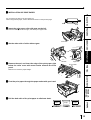
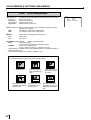
UNPACKING
UNPACKING
PRECAUTIONS
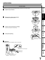
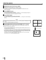
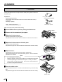
Take the unit out of the box by the following procedures. Make sure to check the contents.
Open the top of the box.
2
Remove the cushion with contents.
3
Take the unit out of the box carefully.
4
Unwrap the packing.
R
EO O
ID SS
R V CE
LO PRO
CO PY
CO
1
FEATURES
R
EO O
ID S S
R V CE
LO PRO
C O PY
CO
Be careful not to drop the contents.
CONNECTIONS PREPARATION
Make sure to keep the unit horizontally.
PRINTING
ADJUSTMENTS
2 CONTENTS
Make sure to check the supplied contents on the cushion.
TROUBLESHOOTING
DISPLAY
COLOR
ADJUST
PROG.
FIELD
/FRAME
Power cord
Attachments for thermal paper
PRINT
Q' ty
SET
MENU
CLEAR
STOP
MEMORY
PAGE
MONITOR
MEMORY
PRINT
OTHERS
Spacers (4)
Screws (4)
COLOUR VIDEO
COPY PROCESSOR
Ink cassette
Wired remote control
Operation manual
7
FEATURES & FUNCTIONS
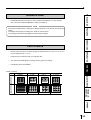
FRONT PANEL
1 2345 6 78 9 A B
ALARM
SHEET
PAPER
S-VIDEO
G
C
D
E
F
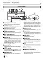
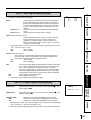
1 POWER BUTTON (INDICATOR)
Press to turn on power. Press again to turn off power.
When the power is turned on, the indicator illuminates.
2 ALARM INDICATOR
When this unit is overheated, this indicator goes on and
off. When other error occurs, it lights up.
pressed, the picture on the monitor screen switches
between the picture of the input signal (source image) and
the memorized image.
When pressing MEMORY button while holding this button,
print paper will be fed and cut automatically, and the
mechanism will be initialized. Make sure to press
MONITOR button first, or a new image will be memorized.
3 SHEET ERROR INDICATOR
A MEMORY BUTTON
4 PAPER ERROR INDICATOR
B PRINT BUTTON
When an error concerning ink sheet occurs, this indicator
lights up.
When an error concerning print paper occurs, this indicator
lights up.
5 INPUT SIGNAL INDICATOR
While S-Video signal is selected for input signal, this lamp
lights up. When other signal is selected, it goes off.
6 MENU BUTTON
Press for color adjustment. The item will be switched in
order of;
SELECT COLOR/B&W→BRT → CONT → R-SUB → G-SUB
→ B-SUB → CENTER[+]→CANCEL[+]→SET[+] → SELECT
COLOR/B&W. (When selecting B&W, R-SUB, G-SUB, B-SUB
change to Y-SUB, M-SUB, C-SUB.)
To go back to the normal screen, press
PLUS(+) button
while SET[+] is selected. See page 32.
8
7 MINUS (-) BUTTON
8
Press to decrease the value of each setting item. To set
the value, select SET[+] in the MENU and press
PLUS
(+) button.
8 PLUS (+) BUTTON
6
Switches the display on the monitor. When this button is
8
Press to print the image memorized by the MEMORY
button. The image on the monitor screen switches to the
source image when printing starts. When image is not
memorized, printing is not available.
C PRINT OUTLET
The printed paper comes out here.
Do not put any objects in front of the outlet.
D OPEN BUTTON
G
Press to slide out the printing mechanism. Make sure to
unlock PRINTING UNIT LOCK SWITCH. When it is not
working, turn off the power once. Then try to press this
button again. Open the mechanism to load paper and ink
cassette or to clear a paper jam.
E TRAY
Holds the printed paper which was come out from the print
outlet. Lift the knob to pull out the tray. Make sure to pull it
out before using this unit.
F REMOTE TERMINAL
G PRINTING UNIT LOCK SWITCH
Connects the remote control supplied.
Press to increase the value of each setting item. To set
the value, select SET[+] in the
MENU and press this
button.
9 MONITOR BUTTON
Press to memorize the image to be printed. When signal
is not inputted, memory is not available.
Locks the printing unit.
Shift the switch to the left (LOCK side) to lock and to the
right (UNLOCK side) to unlock.
This unit is locked when shipping. When transporting this
unit, make sure to lock the unit.
3 4
12
REMOTE
PRECAUTIONS
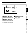
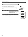
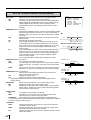
REAR PANEL
IN
OUT
S-VIDEO
AC LINE
OUT
FEATURES
IN
VIDEO
5
This is used to equalize the potential of the equipment
connected to the unit.
For details, refer to the installation instruction of the
equipment to be connected.
1 REMOTE TERMINAL 2 (MINI DIN 8 PIN)
Memorizing images and printing are available by the remote
signal inputted through this terminal. It is necessary to make
a circuit for remote control to use the function. See page
27.
2 REMOTE TERMINAL 1 (STEREO JACK)
4 VIDEO INPUT/OUTPUT TERMINAL
Use these terminals to connect this unit to VIDEO signal
equipment. See page 11.
5 AC LINE SOCKET
Connects to the provided power cord. Insert the cord firmly.
PRINTING
Memorizing images is available by the remote signal
inputted through this terminal. It is necessary to make a
circuit for remote control to use the function. See page 26.
CONNECTIONS PREPARATION
Potential equalization connector
3 S-VIDEO INPUT/OUTPUT TERMINAL
Use these terminals to connect to S-VIDEO signal
equipment. See pages 11.
ADJUSTMENTS
TROUBLESHOOTING
OTHERS
9
FEATURES & FUNCTIONS
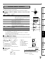
REMOTE CONTROL UNIT
12
9
A
B
C
D
E
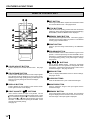
5 SET BUTTON
DISPLAY
COLOR
ADJUST
PROG.
FIELD
/FRAME
PRINT
Q' ty
MENU
SET
CLEAR
STOP
MEMORY
PAGE
MONITOR
MEMORY
PRINT
3
4
5
6
7
8
Press to go to SAVE PRG. Repress to memorize the values
and exit the MENU mode. See pages 28-29.
6 STOP BUTTONS
Press to cancel the printing process and start mechanical
initializing. When pressing these buttons during displaying
MAIN MENU, SERVICE MENU will be displayed.
7 MEMORY PAGE BUTTON
Use to select the image memorized . The memory page is
switched every time this button is pressed. The selected
memory page mark illuminates.
8 PRINT BUTTON
Press to print the image memorized by the MEMORY
button.
9 PROGRAM BUTTON
Press the PROG. button to select between 3 types of user
presets. Functions previously set with the MENU can be
stored into 1 of 3 memories and recalled. Programs cannot
be changed during printing. It may take longer to change
the program.
1 COLOR ADJUST BUTTON
Press to display the COLOR ADJUST menu. See page
32.
2 FIELD/FRAME BUTTON
Press to switch FRAME and FIELD mode of input signals.
The selected mode is displayed on the monitor screen.
FRAME is good for high quality printing of still images, and
FIELD is good for printing fast movement images.
See page 17.
A {, }, [, ] BUTTONS
Use to set the MENU display. Values are increased/
decreased and the cursor position is changed with these
four buttons. These buttons are also used to select one of
memorized images. See page 30 and 37.
B MENU BUTTON
Press to display MAIN MENU used for various settings.
See pages 28-29.
C CLEAR BUTTONS
Press to eliminate all or a part of memorized images.
3 DISPLAY BUTTON
D MONITOR BUTTON
4 PRINT QUANTITY {, } BUTTONS
E MEMORY BUTTON
Press to display the set condition on the monitor screen.
Press again to switch off the display.
Use to set the number of copies to be printed. The set
number of copies is displayed on the monitor screen. Press
to increase the number and
to decrease the number.
When pressing
or
button during printing, the counter
becomes “1” and continuous printing is cancelled. It also
cancels the reserved printing.
See page 22.
{
10
{ }
}
Press to switch the image of the input signal and the
memorized image.
Use to memorize the image to be printed. The memorized
image is displayed on the monitor screen for one second,
then the image of the input signal is displayed.
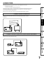
CONNECTIONS
PRECAUTIONS
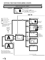
The functions of this unit can be set by the menu screens displayed on the monitor.
• Connection with a monitor
• Connection with VIDEO/S-VIDEO signal equipment
Connect this unit with a monitor to check the images to be printed and the images stored in memory.
The following example shows the connection with a video signal and S-video signal equipment.
Connect with the necessary signal equipment.
Make sure to turn off the power of the unit and connecting equipment before connection.
FEATURES
CONNECTION WITH A MONITOR
Make sure to turn off the power of the unit and connecting equipment before connection.
(EXAMPLE)
CONNECTIONS PREPARATION
To S-VIDEO IN terminal
To S-VIDEO OUT terminal
S-VIDEO OUT
To VIDEO IN terminal
To VIDEO OUT terminal
VIDEO OUT
REMOTE
IN
OUT
S-VIDEO
IN
VIDEO
OUT
AC LINE
VCP
Monitor
PRINTING
CONNECTION WITH VIDEO OR S-VIDEO SIGNAL EQUIPMENT
ADJUSTMENTS
Make sure to turn off the power before setting.
To VIDEO IN terminal
VIDEO IN
REMOTE
OUT
IN
S-VIDEO
AC LINE
S-VHS HOME CAMERA
VIDEO signal
equipment
OUT
TROUBLESHOOTING
S
IN
VIDEO
To VIDEO OUT
terminal
VCP
To S-VIDEO IN terminal
S-VIDEO IN
OUT
IN
S-VIDEO
IN
VIDEO
OTHERS
REMOTE
OUT
S-VIDEO signal equipment
CONFORTABLE LD PLAYER DP-L2000
AC LINE
VCP
To S-VIDEO OUT terminal
11
BEFORE OPERATION
Before printing,
1. Unlock the printing unit. (See below)
2. Install the print paper and ink cassette. (pages 12-15)
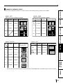
PAPER SHEET SET
When using this unit for printing, make sure to use the following types of paper sheet and ink sheet set.
2 PAPER SHEET SET
Product name
CK900S
CK900L
CK900S4P
CK900L4P
CK900S4P(HX)EU
CK900L4P(HX)EU
Ink sheet size
S size
L size
S size
L size
S Size
L Size
No. of prints
200
130
130
90
130
90
Product name
K65HM-CE
Print size
S/L size
No. of prints
S size Approx.200
L size Approx.125
Product name
PKC900S
PKC900L
Ink sheet size
S size
L size
No. of prints
200
130
2 THERMAL PAPER
2 PAPER INK SHEET CASSETTE
Usage
Colour print
Colour print
Surface-laminated colour print
Surface-laminated colour print
Surface-laminated colour print for ID photo
Surface-laminated colour print for ID photo
Usage
Thermal print
Usage
Colour print
Colour print
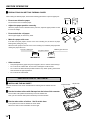
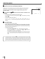
UNLOCK THE PRINTING UNIT
2 RELEASING THE PRINTING UNIT LOCK
1
1 Press down the knob to pull out the tray.
2
2 Shift the printing unit lock switch to the right (UNLOCK). (See page 8.)
INSTALLATION OF PRINT PAPER
with gear
When using the thermal paper, prepare the following steps first.
1 Set the supplied paper attachments to both sides of the thermal paper.
NOTE
Set the attachment with gear on the left side.
Make sure to set them correctly.
2Pull out the thermal paper about 20 cm and cut it.
Remove the part with seal paste, dust and fingerprints.
3Cut the both corners of the paper.
Installation for ther thermal paper is completed.
About 20cm
12
without gear
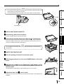
2 INSTALLATION OF PRINT PAPER
PRECAUTIONS
Do not remove the seal on the print paper yet.
When using thermal paper, remove the seal as shown on the previous page.
Gear
Seal
1 Insert the print paper roller with gear on the left.
1 as shown right, and set the print paper roller.
FEATURES
Press the folder
2
1
CONNECTIONS PREPARATION
2 Set the other side of roller without gear.
Front side
1
Right side
arrow marks
PRINTING
3 Remove the seal, and insert the edge of the print paper right
Left side
below the roller cover with arrow marks towards the front
panel.
Make sure to insert the paper straight.
ADJUSTMENTS
4 Feed the print paper through the paper outlet with your hand.
TROUBLESHOOTING
5 Pull the both side of the print paper to eliminate slack.
Paper
OTHERS
Paper
Paper
13
BEFORE OPERATION
2 PRECAUTIONS ON SETTING THERMAL PAPER
When setting the thermal paper, observe the following precautions to prevent paper jam.
• Do not use defective paper.
Do not use the bent or wrinkled paper.
• Adjust the paper position correctly.
When the paper is fed out skewed from the print exit, adjust the paper position so that
it is fed out straight.
• Do not slack the roll paper.
Set the paper tightly to remove any slack.
• Make the paper side even.
If the side of the print paper is uneven or the core is sticking out, the amount of paper
feeding after printing may vary.
When the side of paper is uneven or the core is sticking out, install the print paper after
making the paper side even.
The core is sticking out.
The paper is uneven.
INCORRECT
Make the paper side even.
CORRECT
• Other cautions
•
•
Keep the high-density paper away from fingerprint, dust or moisture when storing it.
Do not touch the rubber roller. Do not stain or damage the roller surface.
•
Do not touch the thermal head (located inside the unit). When printing, the thermal
head is heated to high temperature.
•
Do not touch the cutter blade.
INSTALLATION OF INK SHEET
2 INSTALLING THE INK SHEET
Load the ink sheet roll to the ink cassette before inserting the ink cassette into the
printer.
1 Put the ink sheet rollers with flat tops into the holes of ink cassette.
Put the white roller (rolled with ink sheet) to the ink cassette first.
Then, put the coloured roller (without ink sheet) to the ink cassette.
2 Put the other sides of rollers. Set IC at this time.
IC chip with the IC holder is attached to the ink sheet.
Set the IC holder to the ink cassette as shown right.
14
White roller
Coloured roller
NOTE
Do not remove the IC chip or IC holder from the ink sheet. Removal of the IC will
•
stop the printer from functioning correctly.
Set the projected part of the IC holder to the correct position as shown below.
IC holder
PRECAUTIONS
•
FEATURES
Projected part
CONNECTIONS PREPARATION
2 INSTALLING THE INK CASSETTE
1 Eliminate any slack of the ink sheet.
Hold the coloured roller and turn the white roller.
2 Insert the ink cassette with the ink sheet into its compartment.
1
Put the ink cassette of the ink sheet with flat top side to each . Then, set the other
side (with handle) as shown right. When exchanging the ink cassette and so on,
remove it by holding the handle. (See page 47.)
1
1
PRINTING
NOTE
Do not install the ink cassette when printing with thermal paper, otherwise printing
may be failed.
ADJUSTMENTS
2 INSERT THE PRINTING UNIT
1 Push the printing unit until it is locked into place.
2 After plugging the power cord, press POWER button on the front
2
2
panel.
TROUBLESHOOTING
3 After the set conditions are displayed on the monitor, press
MEMORY button about 1 second with holding MONITOR button on
the front panel.
The print paper is automatically cut after feeding about 10 cm (4 inches).
OTHERS
4 Repeat the above step 3 once or twice.
Fingerprints and dust can be removed by feeding the print paper. The printing unit is
initialized.
15
BEFORE OPERATION
•
•
•
3 4
NOTE
Make sure to press MONITOR button first for operating
and .Pressing MEMORY
button first operates to memorize the images. When exchanging the printing paper or
ink cassette during using the unit, the recorded images may be erased by pressing
MEMORY button first.
Do not feed the print paper more than 2 times. Doing so will not allow the number of
prints indicated on page 12 to be printed.
When thermal paper is running out, red lines appear on both sides of the paper. Install
a new roll of paper, otherwise printing may be failed.
The installation of print paper and ink cassette is completed.
NOTE
An IC is built in the ink sheet. This is the IC chip, not a battery.
This IC can be thrown away as normal waste.
NOTE
If the power is turned on and AUTO FEED&CUT on SYSTEM SETUP menu is set to ON,
“SET PAPER” on the monitor disappears when print paper is inserted under the roller.
(For AUTO FEED&CUT setting, refer to page 38.) After inserting ink sheet and closing
the printing mechanism, the print paper is automatically fed and cut twice.
NOTE
Take the print paper one by one after completing printing. Pull out the tray completely
when using it. If you fail to do so, paper jamming may occur.
Put the tray back when finishing printing.
USAGE AND KEEPING OF PAPER SHEET SET
2 BEFORE PRINTING
•
•
Fingerprints or dust on the paper’s surface may degrade print quality and cause paper
jams. Immediately after the paper is replaced, 2 images may be printed with a blank
part due to hand’s dust or oil. Refer to Pages 12-13.
When print paper is rapidly transferred from a cool place to a hot place, vapour or dew
will be generated on the paper’s surface causing paper jams or degraded print quality.
Leave the print paper in the room to stabilize its temperature before using it.
•
When print paper and ink sheet run out during printing, the printing operation stops and
the error messages such as “CHANGE PAPER” and “CHANGE INK” is displayed on
the monitor. Set new ink sheet or print paper. Refer to Pages 12-15.
2 AFTER PRINTING
•
•
When the printed paper is touched by a wet hand, the print may be discoloured.
Fading may occur if the print-face is exposed to organic chemical agents which may
•
affect print paper (e.g. alcohol, ester, ketone based).
Fading will be accelerated upon contact with PVC-based materials (e.g. adhesive
•
tapes, rubber erasers, etc.).
Avoid storing prints in direct sunlight or places with high humidity.
•
Leaving the print paper in contact with PVC-based materials causes color of print
•
paper to come off and to be stained.
Never store print paper in places that are close to heater, hot, humid or dusty.
2 STORAGE
Keep print paper in a place where;
Temperature : 5°C - 30 °C
Humidity
16
: 20 % - 60 %RH
PRINTING (BASIC)
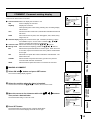
DISPLAY
2 SELECTING FIELD/FRAME
COLOR
ADJUST
FIELD
/FRAME
PRECAUTIONS
BEFORE PRINTING
PROG.
PRINT
Q' ty
MENU
SET
CLEAR
STOP
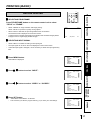
Press FIELD/FRAME button on the remote control unit to select
“FIELD” or “FRAME”.
Select “FRAME” for a high resolution still image printing.
•
Select “FIELD” for a picture of quickly moving objects.
When “FIELD” is selected, the print image will be lower in resolution.
•
The selected mode is displayed on the monitor screen.
A video picture is normally composed of two slightly lower resolution images (FIELD
images) to form a single image (FRAME image).
PRG. 1
VIDEO
Q'ty 1
[ABC] FRAME
FEATURES
•
LIVE
•
•
Select VIDEO or S-VIDEO according to the input signal.
The input signal can be set on the menu displayed on the monitor screen.
•
Unless the input signal is changed, it is not necessary to select the input signal every
time.
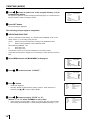
1 Press MENU button.
MAIN MENU is displayed.
•
•
“SAVE PRG 1/2/3/CANCEL” is selected.
This menu lets you select a program memory (1-3) to store your new settings.
MAIN MENU
INPUT
VIDEO / S-VIDEO
COLOR ADJ
LAYOUT
PRINT
COMMENT
MEMORY POSITION
SAVE PRG 1 / 2 / 3 / CANCEL
TROUBLESHOOTING
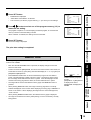
4 Press SET button.
MAIN MENU
INPUT
VIDEO / S-VIDEO
COLOR ADJ
LAYOUT
PRINT
COMMENT
MEMORY POSITION
SAVE PRG 1 / 2 / 3 / CANCEL
ADJUSTMENTS
3 Press[, ] button to select “VIDEO” or “S-VIDEO”.
MAIN MENU
INPUT
VIDEO / S-VIDEO
COLOR ADJ
LAYOUT
PRINT
COMMENT
MEMORY POSITION
SAVE PRG 1 / 2 / 3 / CANCEL
PRINTING
2 Press {, } button to select “INPUT”.
CONNECTIONS PREPARATION
2 SELECTING INPUT SIGNAL
OTHERS
MAIN MENU
INPUT
VIDEO / S-VIDEO
COLOR ADJ
LAYOUT
PRINT
COMMENT
MEMORY POSITION
SAVE PRG 1 / 2 / 3 / CANCEL
17
PRINTING (BASIC)
5 Press [, ] button to select one of the program memory (1-3) to
memorize the setting.
The program is replaced. In case of keeping the stored program, do not select the user
memory number in which the setting is stored.
MAIN MENU
INPUT
VIDEO / S-VIDEO
COLOR ADJ
LAYOUT
PRINT
COMMENT
MEMORY POSITION
SAVE PRG 1 / 2 / 3 / CANCEL
6 Press SET button.
The source image is displayed.
The selecting of input signal is completed.
2 SELECTING PRINT SIZE
•
“AUTO” is selected for initial setting. “S” is selected when THERMAL is set to “ON”.
•
Select “AUTO” or “S” according to the print size.
AUTO : Selects print size automatically according to the installed ink sheet.
S:
Selects S size regardless of the installed ink sheet.
When selecting THERMAL : ON,
L:
S:
•
•
Prints with L size.
Prints with S size.
The print size can be set on the menu displayed on the monitor screen.
Unless the ink sheet size is changed, it is not necessary to select the print size every
time.
1 Press MENU button and MAIN MENU is displayed.
2 Press {, } button to select “LAYOUT”.
3 Press ] button.
•
•
LAYOUT is displayed.
Normally, “MODE” is selected when opening LAYOUT. When other item is
selected, press
or
button to select “MODE”.
{ }
4 Press [, ] button to select “AUTO” or “S”.
(Select “L” or “S” when THERMAL is set to ON.)
•
•
18
Select “AUTO” for normal setting. Select “S” to print S size with L size ink sheet.
When printing with thermal paper, L or S size printing is available by selecting “L” or “S”.
MAIN MENU
INPUT
VIDEO / S-VIDEO
COLOR ADJ
LAYOUT
PRINT
COMMENT
MEMORY POSITION
SAVE PRG 1 / 2 / 3 / CANCEL
MAIN MENU
INPUT
VIDEO / S-VIDEO
COLOR ADJ
LAYOUT
PRINT
COMMENT
MEMORY POSITION
SAVE PRG 1 / 2 / 3 / CANCEL
LAYOUT
MODE
MULTI
MODE
IMAGES
SIZE
LAYOUT
MODE
MULTI
MODE
IMAGES
SIZE
AUTO/S
OFFOFF(PRN SELECT)//ON
SAME/DIFF/PHOTO1
2/2S/4/16
W/M/N/USER
AUTO/S
OFF/OFF(PRN SELECT)/ON
SAME/DIFF/PHOTO1
2/2S/4/16
W/M/N/USER
•
•
MAIN MENU is displayed.
“SAVE PRG 1/2/3/CANCEL” is selected.
•
This menu lets you select a program memory (1 - 3) to store your new settings.
memorize the setting.
The program is replaced. In case of keeping the stored program, do not select the
memory number in which the setting is stored.
When “CANCEL” is selected, the settings are not memorized.
MAIN MENU
INPUT
VIDEO / S-VIDEO
COLOR ADJ
LAYOUT
PRINT
COMMENT
MEMORY POSITION
SAVE PRG 1 / 2 / 3 / CANCEL
MAIN MENU
INPUT
VIDEO / S-VIDEO
COLOR ADJ
LAYOUT
PRINT
COMMENT
MEMORY POSITION
SAVE PRG 1 / 2 / 3 / CANCEL
FEATURES
6 Press [, ] button to select one of the program memory (1-3) to
PRECAUTIONS
5 Press SET button.
CONNECTIONS PREPARATION
7 Press SET button.
The source image is displayed.
The print size setting is completed.
MEMORY PRINT
In the single image mode, this unit has 3 FRAMES of image memory and the following
functions are available.
Each time the FIELD/FRAME button is pressed, the display changes to show the
Field or Frame mode.
•
Frames are shown as [ABC]FRAME, and since one Frame consists of two Fields, the
Frame letter is shown (in green) along with the Field display as “1” or “2” (in green) as
[ABC]FIELD1/[ABC]FIELD2.
Press MEMORY PAGE button to advance the Memory Page to the next Field or
Frame. The selected page number is shown in green. The memory page in which
the next image will be memorized is shown in yellow. If the selected page number
•
and the next memory page are the same, the number will be shown in yellow.
The image will be stored in the selected memory page when MEMORY button is
•
pressed.
When pressing MONITOR button, the image of memory page which is currently
VIDEO
Q'ty 1
[ABC] FRAME
LIVE
ADJUSTMENTS
•
PRG. 1
PRINTING
•
Available memory page (A is
chosen).
[ABC]FIELD1 or [ABC]FIELD2
is displayed for FIELD.
[ABC]FRAME is displayed for
FRAME.
TROUBLESHOOTING
selected is displayed on the monitor. When displaying a memory page, “MEMORY” is
shown on the monitor. When displaying the image from the connected equipment,
“LIVE” is shown.
When pressing MEMORY PAGE button, the selected memory page is displayed.
•
An image can be stored into memory while printing, but not in the memory currently
being printed.
OTHERS
19
PRINTING (BASIC)
2 MEMORIZING AND PRINTING AN IMAGE
1 Display the image which you wish to print.
•
The memory page can be changed by pressing MEMORY PAGE button on the
remove control unit.
2 Press MEMORY button.
•
•
The selected page is shown in yellow.
When pressing MONITOR button to show “MEMORY” on monitor display, the image on
the selected memory page will be displayed on monitor.
3 Press PRINT button.
•
•
The image displayed on the monitor will be printed.
The memory page during print stand-by is shown as “-”, and it goes on and off during
printing.
NOTE
When selecting OFF(PRN SELECT) in MULTI, 4 memory pages are displayed on the
monitor.
However, only selecting page can be printed.
PRG.1
A
2 IMAGE MEMORIZING WITH PAGE INCREMENT SET TO PAGE
When INCREMENT is set to “PAGE” (automatic memory page advance system), the
followings are the memory operations.
•
•
•
Every time pressing MEMORY button, the memory page is switched in order of A→B→C,
and image will be memorized in it.
To memorize an image on a memory page you selected, press MEMORY PAGE button
first to select the memory page. Then, press MEMORY button to memorize the image.
When selecting OFF(PRN SELECT) in MULTI, the memory page is switched in order
of A→B→C→ D→A→B... by pressing MEMORY button.
For FIELD, the memory page is switched in order of A1→B1→C1→D1→A2→B2→
C2→D2→A1→B1....by pressing MEMORY button.
Q'ty 1
B
C
RGB
D
FRAME
AB
CD
Memory page display
Selecting A and printing it.
A
(example) S size printing
20
MEMORY
PRECAUTIONS
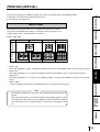
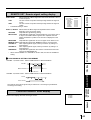
2 NUMBER OF MEMORY PAGES
As this unit has 1280 pixel x 600 lines x 3 frames of memory, the following memory operations are available.
MODE : SAME
(Multi printing the same images)
MODE : DIFF
(Multi printing the different images)
1 page
2 pages
16
2 pages
1
2
3
4
FIELD
4
3 pages
6 pages
3
4
1
2
3
7
8
5
6
7
8
9
10
11
12
9
10
11
12
13
14
15
16
13
14
15
16
16
3 pages
6 pages
4
MULTI : OFF
PRINT EXAMPLE
(S size print)
MULTI
13 14 15 16
7 8
9 10 11 12
3 4
2 3 4
5 6
6 pages
5x5
3 pages
6 pages
1 2
3 x 3.5
3 pages
6 pages
1 2 3
4 5 6
FIELD
PRINT EXAMPLE
3 pages
6 pages
1
4 pages 8 pages
1
TROUBLESHOOTING
3 pages
OFF
(PRN
SELECT)
FRAME
ADJUSTMENTS
3x4
•
4
6
1
6 pages
3
2
1 2
3 pages
2
5
OFF
CARD
1
PRINTING
MULTI
6 pages
1
MODE : PHOTO1
FRAME
3 pages
CONNECTIONS PREPARATION
4
2
2S
PRINT EXAMPLE
FEATURES
2 pages
FIELD
1
1 page
FRAME
MULTI
2
2
2S
PRINT EXAMPLE
1
FIELD
2
FRAME
MULTI
Because the FIELD mode has half the vertical resolution of the FRAME mode, the printed image may be low in quality.
OTHERS
21
PRINTING (BASIC)
2 MULTIPLE COPY OR CONTINUOUS PRINTING
Multiple copies of a memorized image can be made by setting the number of prints to
more than one. The print quantity can be set for up to 200 prints or for continuous
No. of print setting
PRG. 1
Q'ty 1
printing until the paper or ink sheet is used up. Multiple quantity printing can be
cancelled if needed.
1 Press PRINT Q’ty {,} button to set the number of sheets to be
printed.
•
•
The number of prints is displayed on the monitor screen.
The number will increase by pressing PRINT Q’ty
and decrease by pressing
•
PRINT Q’ty .
The number switches in the order of;
{
}
1←→2← • • • → 9 ←→ 10 ←→ 20 ←→ 30 ←→ 40 ←→ 50 ←→ 100 ←→ 200 ←→ C ←→ 1
When you set to “C”, continuous printing will be done until the paper or ink sheet is
used up.
2 Press PRINT button.
•
The number of prints you set is printed.
•
During continuous printing (except for selecting “C”), the set number on the monitor
will be counted down every time one sheet is printed. When printing is completed,
the counter will be reset to the original set number. This will not reset when turning
off the power (It will not be reset to “1”.)
•
If you wish to stop printing;
• Press PRINT Q’ty
and
{
} buttons. After printing the current page,
{ and } buttons are
the counter will be reset to “1.” Pressing PRINT Q’ty
also available to cancel the reserved printing.
•
If you wish to stop printing without completing the current page, press STOP
button. The image will be printed imcompletely and come out from the print
outlet.
NOTE
•
If a blackish image is continuously printed, the internal temperature may rise and
cause the unit to switch to a stand-by condition during printing. In this case, an error
message “OVER HEAT” will be displayed on the monitor. Wait until the error message
goes off. When temperature drops and the message goes off, printing resumes.
22
VIDEO
[ABC] FRAME
LIVE
PRINTING (SPECIAL)
PRECAUTIONS
Various types of printing are available by setting on the menu screen (MAIN MENU and SERVICE MENU).
In this section, some examples of special prints are given.
For each setting, see pages 28-29.
MULTI PRINT
FEATURES
MULTI PRINT is the function which 2, 4 or 16 images can be printed on a sheet.
Use LAYOUT of MAIN MENU for setting. For the setting, refer to pages 32-33. For
PHOTO1 setting, refer to “PHOTO PRINTS” on page 25.
MODE : SAME, DIFF
2
2S
4
16
CONNECTIONS PREPARATION
S size prints L size prints
MODE : DIFF
•
When setting IMAGES to “2(2S)”, 2 images are available to be stored in each FRAME: Page A, or each FIELD1,2: Page A.
MODE :DIFF
•
When setting IMAGES to “4,” 4 images are available to be stored each FRAME: Page A, or each FIELD1,2: Page A.
MODE :DIFF
PRINTING
•
When setting IMAGES to “16,” memory is not available in FRAME. 16 images are available to be stored in each FIELD1,2
Page A.
•
ADJUSTMENTS
MODE : SAME
1 image is available to be stored in each FRAME Page A-C or in each FIELD1,2, Page A-C.
NOTE
When printing 2 images on S size sheet, some characters of the comment will be
clipped.
•
When printing 2 images on L size sheet, the images may be partially clipped. In this
case, adjust the image position by PRN V AREA of LAYOUT2 in SERVICE MENU
TROUBLESHOOTING
•
so that the image moves to the proper position, or use 2S mode. See pages 33 and
40.
OTHERS
23
PRINTING (SPECIAL)
2 WHEN SETTING TO MODE : DIFF, IMAGES :4;
Repeat the following procedure to store the set number of images in memory.
1 Press DISPLAY button to display the set condition.
2 Press MONITOR button and select the source image (“LIVE” is
displayed on the monitor.) to display the image to be stored.
3 Press MEMORY button to store the image to be printed.
•
For normal setting, when the image is stored, the source image (LIVE image) is
displayed after displaying the stored image about 1 second.
4 When selecting the position to store the image, press MEMORY
PAGE button to select the memory page.
•
•
•
{}[}
Press , , ,
button to determine the position to store the image.
The image is stored in the selected memory page.
The position number where the image can be stored is indicated in yellow.
2 WHEN SETTING TO MODE : SAME, IMAGES : 4;
Only one image will be displayed on the monitor screen.
1 Press DISPLAY button to display the set condition.
2 Press MONITOR button and select the source image (“LIVE” is
displayed on the monitor.) to display the image to be stored.
3 Press MEMORY button to store the image to be printed.
•
When the image is stored, the source image (LIVE image) is displayed after
displaying the stored image about 1 second.
(When MEM&MONI : OFF in SERVICE MENU)
4 When selecting the memorizing page (A, B, C), press MEMORY
PAGE button to select .
•
24
The position number where the image can be stored is indicated in yellow.
PRECAUTIONS
SEPARATE PRINT
•
•
The SEPARATE print is a function to insert a white frame between 2 or more images.
Use LAYOUT2 of SERVICE MENU for setting. See page 40.
NOTE
FEATURES
The amount of white frame in multi print is different between on the monitor and the printed
image.
The image size changes according to the “SIZE” in LAYOUT menu.
The setting just before printing applies to all the multi print images.
CONNECTIONS PREPARATION
PHOTO PRINTS
PHOTO print is a function to print the images on the photo size (3 x 4 cm, 5 x 5 cm, 3 x 3.5
cm) and CARD size (2 x 1.5 cm).
•
CARD size print is suited to stick on a business card.
•
Use LAYOUT of MAIN MENU for setting. Refer to page 32 for setting.
•
The following prints are available.
PRINTING
•
MODE : PHOTO1
CARD
3x4
5x5
3 x 3.5
ADJUSTMENTS
TROUBLESHOOTING
S size prints L size prints
OTHERS
25
PRINTING (SPECIAL)
EXTERNAL REMOTE TERMINAL 1
The image can be stored in memory by sending the remote signal through the external
remote terminal on the rear panel. When the MEM&PRN(MEMORY & PRINT) function
is set to ON, the image will be printed after being stored in memory.
• Make out the necessary circuit to use this function by referring to the following.
2 EXTERNAL REMOTE TERMINAL SIGNAL ALLOCATION (STEREO
JACK)
Pin No.
1
2
3
Function
Ground
MEMORY
BUSY1
Description
Earth
Memory : When the signal becomes “LOW” from “HIGH”, the
image is stored in memory. (When the signal has
been “LOW” for 15ms or more, the image is stored
in memory.) See page 42, 43.
Refer to the BUSY LEVEL setting of REMOTE SET in SERVICE
MENU. See page 43.
3
2
1
Circuit inside and pin No.
23 1
Plug pin No.
Circuit inside the VCP
DC5V
DTC124EK
To VCP
10kΩ
22kΩ
22kΩ
•
•
26
When the signal from BUSY terminal is received with TTL level, keep the following.
| IOL | = 2mA or less, | IOH | = 1mA or less
| IOL | means the current flowing into the unit at Low output, | IOH | means the
current flowing out of the unit at High output.
Just after completing printing, there is a period that memory signal is not accepted. From VCP
100Ω
2MEMORY
DC5V
DMC2838
DTC124EK
10kΩ
100Ω
22kΩ
22kΩ
3 BUSY
The image can be stored in memory and printed by sending the remote signal through
12
the external remote terminal on the rear panel.
• Make out the necessary circuit to use this function by referring to the following.
2 EXTERNAL REMOTE TERMINAL SIGNAL ALLOCATION (MINI
34
5
DIN8PIN)
1
2
Description
Earth
MEMORY
Memory : When the signal becomes “LOW” from “HIGH”, the
image is stored in memory. (When the signal has
Pin No.
Circuit inside the VCP
been “LOW” for 15ms or more, the image is stored
in memory.) See page 42, 43.
BUSY2
4
Refer to the BUSY LEVEL setting of REMOTE SET in
SERVICE MENU. See page 43.
BUSY1
To VCP
PRINT
6
REMOTE
When the signal becomes “LOW” from “HIGH”, the image is
stored in memory. (When the signal has been “LOW” for 15ms
10kΩ
22kΩ
22kΩ
Refer to the BUSY LEVEL setting of REMOTE SET in
SERVICE MENU. See page 43.
5
7
8
DC5V
DTC124EK
100Ω
2MEMORY
DC5V
74LVC125
10kΩ
100Ω
From VCP
3 BUSY2
4 BUSY1
TTL level
or more, the image is stored in memory.)
The same functions as the supplied remote control can be
DC5V
74LVC125
10kΩ
100Ω
controlled.
To VCP
Power supply for the remote control DC 1mA Max.
To VCP
TTL level
Unused
DC3V
CONNECTIONS PREPARATION
3
•
67 8
Function
Ground
FEATURES
Pin No.
PRECAUTIONS
EXTERNAL REMOTE TERMINAL 2
1kΩ
56kΩ
5 PRINT
6 REMOTE
When the signal from BUSY terminal is received with TTL level, keep the following.
•
PRINTING
| IOL | = 2mA or less, | IOH | = 1mA or less
| IOL | means the current flowing into the unit at Low output, | IOH | means the
current flowing out of the unit at High output.
Just after completing printing, there is a period that memory signal is not accepted.
2 PIN NO. 6 REMOTE TERMINAL
ADJUSTMENTS
By sending the following remote control codes from pin No.6, the same functions as the wired
remote control unit supplied can be controlled.
[
01:
button
08: PRINT Q’ty
]
02:
button
button
{
0A*: MENU button
0D*
03:
09*
} button
0B*: CLEAR button
0E*: SET button
04:
1.6 ms (T2)
{ button
}
0C: PRINT Q’ty
button
0F*: STOP button
15*: FIELD/FRAME button
18*: DISPLAY button
1C*: MEMORY PAGE button
In case of the codes with * mark, 5 words are sent.
1D*: MONITOR button
2 TIMING CHART
3.2 ms (T3)
TROUBLESHOOTING
12*: PROGRAM button 13*: PRINT button
16*: COLOR ADJ button 17*: MEMORY button
0.4 ms (T1)
0.4 ms (T1)
(The above values are references.)
T4
:
TTL
Input timing
:
1 word 38.4 ms (reference)
1
T1 ≥ 0.4ms
1.5ms < T2 < 2ms
2ms < T3 < 4.2ms
13ms < T4 < 90ms
1
0
0
1
OTHERS
Input signal level
0
1 word
(EXAMPLE) Print code
= 13 = 0 1 0 0 1 1
27
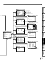
SETTING THE FUNCTIONS (MENU CHART)
MONITOR DISPLAY CHART
OPERATION
COLOR ADJ
SELECT COLOR/B&W
BRT
: 0
CONT
: 0
R-SUB
: 0 C
G-SUB
: 0 M
B-SUB
: 0 Y
CENTER
CANCEL
Monitor display
Select MENU with { ,} button.
R
G
B
Press [ , ] button to change the value,
select the mode or switch the item.
STOP
p
p32
is reference page.
COLOR
ADJ
is the name of button
on remote control.
is the name of button
on front panel.
*1 When going back to MAIN MENU
or SERVICE MENU without
saving the setting, press
MENU button.
p32
POWER
ON
p34
p30
Set conditions display
Q'ty 1
MENU
SET
VIDEO
S-VIDEO
[ABC] FRAME
[ABC] FIELD1 2
LIVE
MEMORY
DISPLAY
Source image
MAIN MENU
INPUT
VIDEO/S-VIDEO
COLOR ADJ
LAYOUT
PRINT
COMMENT
MEMORY POSITION
SAVE PRG 1/2/3/CANCEL
AUTO/S
OFF/OFF(PRN SELECT)/ON
SAME/DIFF/PHOTO1
2/2S/4/16
W/M/N/USER
OFF/W/M/N>
0 (0~ -48)>
0 (0~ -48)>
0 (0~ -63)>
0 (0~ -63)>
S/N/H1/H2
NOR/REV
OFF/ON
FAST/NORMAL
MENU
*1
p35
SET
ABCDEFGHIJKLMNOPQRSTUVWXYZ
abcdefghijklmnopqrstuvwxyz
0123456789
+-*/,.;:'"?! ( ) < >#%& $ Y
[LEFT][RIGHT]
SET
[INS][DEL]
SET
[CANCEL]
SET
[SAVE]
SET->MAIN MENU
Memory and Position
setting display
DISPLAY
MEMORY POSITION
LINE
OFF/ON
H-POSI
0
V-POSI
0
*2
When selecting MODE:DIFF,
IMAGES 2/2S/4/16 are available.
When selecting MODE:PHOTO1,
IMAGES card/3*4/5*5/3*3.5 are available.
To Set Conditions display
28
L/S is displayed when
selecting THERMAL : ON
Displays only when
MULTI : ON *2
2S is not displayed when
selecting THERMAL : ON
Displays only when
selecting SIZE : USER
Only NORMAL is
available when
selecting IMAGES:2S
or using CK900S4P(HX)EU
or CK900L4P(HX)EU.
Only FAST is available when
selecting THERMAL : ON.
Comment making display
COMMENT OFF/ON[SET]/ADJ/DATA
p36
Changes to Y-SUB,
M-SUB, C-SUB
when selecting
SELECT : B&W
Print setting display
PRINT
APT
DIR
MIRROR
PRN SPEED
MAIN MENU display
R
G
B
Layout setting display
LAYOUT
MODE
MULTI
MODE
IMAGES
SIZE
<COPY
<TOP
<BOTTOM
<LEFT
<RIGHT
Front panel
PRG. 1
Colour adjustment display
COLOR ADJ
SELECT COLOR/B&W
BRT
: 0
CONT
: 0
R-SUB
: 0 C
G-SUB
: 0 M
B-SUB
: 0 Y
CENTER
CANCEL
System setting display
SYSTEM SETUP
INCREMENT
OFF/PART/PAGE
BUZZER
OFF/T1/T2
REMAINING Q'ty
10
REMAIN NOTICE
OFF/BZ/PRN/B&P
REMAINING SCREEN
OFF/ON
ERROR SCREEN
OFF/ON
AUTO FEED&CUT
OFF/ON
THERMAL
OFF/ON
PAPER HOLD
OFF/ON
INIT PROG
ALL/MAIN/SERVICE
INITIALIZE
OFF/GO[SET]
Does not display when
selecting THERMAL : ON
Only OFF is available when
selecting THERMAL : ON
AUTO CUT OFF/ON is displayed when
selecting THERMAL : ON
Gamma level setting display
GAMMA ADJ INIT [CLEAR]
COLOR
ALL/EACH
<SELECT
R/G/B>
Hi
0
Mid
0
Low
0
POINT 64 128 192
Layout setting display 2
Only OFF is available when
selecting THERMAL : ON
p40
Displays only when
selecting COLOR : EACH
Analog colour
adjustment display
ANALOG COLOR ADJ
INPUT
COLOR/B&W
BRT
0
CONT
0
R-SUB
0 C
G-SUB
0 M
B-SUB
0 Y
COLOR
0
p41
Input signal setting display
INPUT
FIELD
AFC
AGC
DCF
p37
NOR/REV
OFF/ON
OFF/ON
OFF/ON
Displays only when selecting INPUT:VIDEO
p41
Output signal setting display
OUTPUT
MONI R-SUB
MONI B-SUB
MEMORY SYNC
0
0
EXT/INT
MENU
*1
p42
Button function setting display
SET
KEY SET
KEY LOCK
MEM&PRN
MEM&STOP
MEM&MONI
KEEP MONI
AUTO CLEAR
CLEAR KEY
OFF/ON
OFF/ON/R1/R2
OFF/PART/PAGE
OFF/ON
OFF/ON
OFF/MEM/AFTER PRN
PART/PAGE/ALL
p43
ADJUSTMENTS
SET
0
PRINTING
REMOTE
PREVIOUS ERROR
SAVE PRG 1 / 2 / 3 / CANCEL
APT
CENTER
CANCEL
R
G
B
COLOR is not displayed
when selecting B&W in
COLOR ADJ in MAIN MENU.
SERVICE MENU display
SERVICE MENU
SYSTEM
GAMMA ADJ
LAYOUT 2
ANALOG COLOR ADJ
INPUT
OUTPUT
KEY SET
CONNECTIONS PREPARATION
LAYOUT2
PRN V AREA (L2 ONLY) 0(-10~10)
SEPARATE
OFF/ON
MARGIN CUT
OFF/ON
FEATURES
p39
p40
PRECAUTIONS
p38
Remote signal setting display
REMOTE SET
Previous error display
PREVIOUS ERROR
NO ERROR
NO ERROR
NO ERROR
LOW/HIGH
OFF/1/2/1&2
OFF/1/2/1&2
OFF/1/2/1&2
OFF/1/2/1&2
OFF/1/2/1&2
OFF/1/2/1&2
OFF/1/2/1&2
When either one of them is set to OFF,
the other is available for setting.
TROUBLESHOOTING
p43
BUSY LEVEL
BUSY1,2 SELECT
PRINTING
MECHA ERR
MEDIA ERR
MEMORY STOP
STROBE 1V
STROBE 2V
REMAINING
OTHERS
29
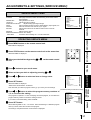
ADJUSTMENTS & SETTINGS (MAIN MENU)
MAIN MENU ITEMS
MAIN MENU is used to open sub-menus. The functions are set with the following 6
menus. The settings can be saved by SAVE PRG.
INPUT
VIDEO
Selects the input signal through the terminal on the rear panel
Signal from video signal input terminal
S-VIDEO
COLOR ADJ
LAYOUT
PRINT
Signal from S-video signal input terminal
Adjusts colour of printing image
Adjusts the image layout setting
Selects image outline, selects print direction, mirror print (left/right
inversed) and print speed
COMMENT
Making a comment
MEMORY POSITION
Selects print position
SAVE PRG Stores the above settings in 1 of 3 user memories
MAIN MENU
INPUT
VIDEO/S-VIDEO
COLOR ADJ
LAYOUT
PRINT
COMMENT
MEMORY POSITION
SAVE PRG 1/2/3/CANCEL
Monitor display
DISPLAY
OPERATING MAIN MENU
PROG.
COLOR
ADJUST
FIELD
/FRAME
Use buttons on the remote control unit to display MAIN MENU and select and set
functions.
PRINT
Q' ty
MENU
SET
CLEAR
1 Press MENU button to display MAIN MENU.
2 Select your desired item by pressing
{
STOP
MAIN MENU
INPUT
VIDEO / S-VIDEO
COLOR ADJ
LAYOUT
PRINT
COMMENT
MEMORY POSITION
SAVE PRG 1 / 2 / 3 / CANCEL
or }.
(EXAMPLE) Selecting LAYOUT display
3 Press
]
button to open a sub menu.
4 Select an item you wish to adjust by pressing
30
{
or }.
LAYOUT
MODE
MULTI
MODE
IMAGES
SIZE
AUTO/S
OFF/OFF(PRN SELECT)/ON
SAME/DIFF/PHOTO1
2/2S/4/16
W/M/N/USER
LAYOUT
MODE
MULTI
MODE
IMAGES
SIZE
AUTO/S
OFF/OFF(PRN SELECT)/ON
SAME/DIFF/PHOTO1
2/2S/4/16
W/M/N/USER
5 Press
[
or ] button to select an item or change value.
6 Press SET button.
This menu lets you select a program memory (1 - 3) to store your new settings.
AUTO/S
OFF/OFF(PRN SELECT)/ON
SAME/DIFF/PHOTO1
2/2S/4/16
W/M/N/USER
OFF/W/M/N>
0 (0~ -48)>
0 (0~ -48)>
0 (0~ -63)>
0 (0~ -63)>
MAIN MENU
INPUT
VIDEO / S-VIDEO
COLOR ADJ
LAYOUT
PRINT
COMMENT
MEMORY POSITION
SAVE PRG 1 / 2 / 3 / CANCEL
FEATURES
“SAVE PRG 1/2/3/CANCEL” is displayed.
LAYOUT
MODE
MULTI
MODE
IMAGES
SIZE
<COPY
<TOP
<BOTTOM
<LEFT
<RIGHT
PRECAUTIONS
If you press MENU button, the settings will be canceled and MAIN MENU is displayed.
7 Press
CONNECTIONS PREPARATION
[ or ] button to select the program memory numbers of
1, 2 or 3 to store the setting.
The program is replaced. In case of keeping the stored program, do not select the
program memory number in which the setting is stored.
If you wish to cancel the setting, select CANCEL and press SET button.
8 Press SET button.
When selecting PRG1 to set, “1” is chosen. When memorizing in a different program
memory number, select the number of the program.
•
As the program is replaced, it is recommended not to choose the program number
which has been selected in the step .
•
The memorized program will be selected by pressing PROG button, and the image
which follows each setting is displayed. However, you cannot change the setting
PRINTING
7
of selected program during printing. You can store only 1 kind of program set in
COMMENT menu. The setting values of TOP, BOTTOM, LEFT, RIGHT in LAYOUT
ADJUSTMENTS
•
menu can be memorized in each 2, 2S, 4, 16 of IMAGES.
The image will be printed according to the selected memory program.
NOTE
The settings can be stored in each program number 1 to 3 in MAIN MENU and SERVICE
MENU. When selecting the program number in which the setting is stored, the same
program numbers of MAIN MENU and SERVICE MENU are automatically selected.
(When selecting program 1 in MAIN MENU, program 1 in SERVICE MENU is also
TROUBLESHOOTING
selected automatically.)
OTHERS
31
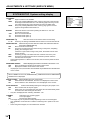
ADJUSTMENTS & SETTINGS (MAIN MENU)
COLOR ADJ Colour adjustment display
•
•
The colour of the source image and memorized image can be adjusted.
Open this menu also by pressing the COLOR ADJ button on the remote control unit.
SELECT
COLOR
B&W
BRT (Bright)
Selects colour print or black and white print.
Colour print
Black and white print (The monitor shows in colours.)
Adjusts brightness of the printing image. (The whole image will be
adjusted.)
CONT (Contrast)
Adjusts contrast of the printing image. (The image will be adjusted
based on the black level.)
R-SUB
Adjusts red-subcontrast of the printing image. Red is added with
] and blue is added with [.
G-SUB
Adjusts green-subcontrast of the printing image. Green is added
with ] and pink is added with [.
B-SUB
Adjusts blue-subcontrast of the printing image. Blue is added with
] and yellow is added with [.
CENTER
When pressing ], the values of BRT, CONT, R-SUB G-SUB and
B-SUB will be reset to 0.
CANCEL
Cancels the change of COLOR ADJ and resets to the stored setting.
• When selecting B&W, R-SUB, G-SUB and B-SUB change to Y-SUB, M-SUB, CSUB. When selecting THERMAL : OFF (colour print), each value of Y-SUB, MSUB and C-SUB is available to adjust the colour of the printed image. When selecting
THERMAL : ON (thermal print), only Y-SUB value is available and function as the
density of gray colour of the printed image.
• When SELECT is changed from COLOR to B&W, the set values of R-SUB, G-SUB,
and B-SUB function as the density of gray colour.
COLOR ADJ
SELECT COLOR/B&W
BRT
: 0
CONT
: 0
R-SUB
: 0 C
G-SUB
: 0 M
B-SUB
: 0 Y
CENTER
CANCEL
R
G
B
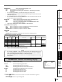
LAYOUT Layout setting display
MODE
Selects the print size. Normally select the ink sheet size which is
installed in this unit. (See page 12 for the print paper.)
AUTO
L size ink sheet.
When S size ink sheet is installed, S size is automatically set.
S
S size ink sheet or S size printing with L size ink sheet, and S size
printing with thermal paper.
L
L size printing with thermal paper.
• When using thermal paper (selecting THERMAL : ON in SYSTEM SETUP menu),
AUTO/S is changed to L/S.
MULTI
Selects ON or OFF for 2, 4, or 16 images on a sheet.
OFF
Multi-image print is not available. 1 image mode.
OFF(PRN SELECT) 4 memory pages display. 1 image mode.
ON
Multi-image print is available.
• When selecting OFF or OFF(PRN SELECT), MODE: SAME/DIFF/PHOTO1 and
IMAGES : 2/2S/4/16 are not displayed.
• When setting AUTO CLEAR to MEM or AFTER PRN in OFF(PRN SELECT), only
selecting page is cleared.
MODE
Selects print mode.
SAME
Prints images of the same scenes on a sheet.
DIFF (Different) Prints images of different scenes on a sheet.
PHOTO1
Prints images in PHOTO mode.
• This menu is displayed only when MULTI : ON is selected.
32
LAYOUT
MODE
MULTI
MODE
IMAGES
SIZE
<COPY
<TOP
<BOTTOM
<LEFT
<RIGHT
AUTO/S
OFF/OFF(PRN SELECT)/ON
SAME/DIFF/PHOTO1
2/2S/4/16
W/M/N/USER
OFF/W/M/N>
0 (0~ -48)>
0 (0~ -48)>
0 (0~ -63)>
0 (0~ -63)>
IMAGES
When selecting MODE : PHOTO1, the following sizes are available.
CARD
20mm x 15mm
3*4
30mm x 40mm
5*5
50mm x 50mm
3 * 3.5
30mm x 35mm
CONNECTIONS PREPARATION
SIZE
FEATURES
•
PRECAUTIONS
Selects the number of images on a sheet. Is displayed when setting
MULTI: ON.
2
2-images on a sheet. (2 S-size images can be printed in L size
print. However, the top and bottom of the image will be clipped.)
2S
2 reduced images on a sheet. (For L size print, the images can be
printed without clipping by reducing S size images. In the case, the
printing speed (PRN SPEED) becomes NORMAL. For S size print,
2 images can be printed as the same result as 2 mode.)
4
4-images on a sheet
16
16-images on a sheet
• 2S is not displayed when selecting THERMAL : ON.
Sets the print area of the image. Choose from 3 preset print areas or a user
selectable area.
Printed image size of 1 image mode(mm)
(S size)
(L size)
•
W
M
100X75
94X70
125X94
118X89
N
USER
90X68
113X85
Optional size by user
Part of the image may be clipped from the print depending on the print size.
COPY
Copies a printed image size which is set W, M, or N in size. The
selected setting level is displayed as TOP, BOTTOM, LEFT and
RIGHT. These levels become the changing base.
PRINTING
•
ADJUSTMENTS
TOP/BOTTOM/LEFT/RIGHT
Sets the printing area of the image. Adjust the size with [ or ]
button.
TOP
Shifts the upper end of the image (setting area : 0 to -48)
BOTTOM
Shifts the lower end of the image (setting area : 0 to -48)
LEFT
Shifts the left end of the image (setting area : 0 to -63)
RIGHT
Shifts the right end of the image (setting area : 0 to -63)
NOTE
When monochrome signal is input, colours may not be added to the characters
displayed on the monitor. In that case, set SELECT of ANALOG COLOR ADJ MENU
to “B&W” in SERVICE MENU.
•
TROUBLESHOOTING
When SIZE is set to W or the minus value is increased on H-POSI, the monitor
screen may get darker according to the monitor connected. However, the image
will be printed correctly.
OTHERS
33
ADJUSTMENTS & SETTINGS (MAIN MENU)
PRINT Print setting display
APT (Aperture)
S (SOFT)
N (NORMAL)
H1 (HARD 1)
H2 (HARD 2)
Controls apertures and reinforces or softens the contour of image.
Softens the contour.
Does not perform APT.
Reinforces the contour.
Reinforces the contour more.
DIR (Print direction) Selects printing direction. The left and right margin sizes will be
different on L size paper.
NOR
The margin is made on the lower position.
REV
The margin is made on the upper position.
MIRROR
OFF
ON
Selects the mirror (left/right inversed) prints.
Normal print
Mirror print
PRN SPEED (Printing speed)
Selects the printing speed.
FAST
High speed printing
(S size : 1280 dots (100mm) x 600 lines (75mm))
NORMAL
Prints lines in double density.
(S size : 1280 dots (100mm) x 1200 lines (75mm))
• Only NORMAL is available when using CK900S4P(HX)EU or CK900L4P(HX)EU or
selecting IMAGES : 2S.
• ONLY FAST is available when selecting THERMAL : ON.
Examples of SIZE, DIR and MIRROR setting
(This image is limited in printing with white by SIZE setting.)
Standard print
When the values of TOP
and RIGHT are small and
MIRROR is ON
34
When the values of
TOP and RIGHT are
small
When the values of
BOTTOM and LEFT
are small
When the values of TOP
and RIGHT are small
and DIR is REV
When the values of TOP
and RIGHT are small and
MIRROR is ON and DIR is
REV
PRINT
APT
DIR
MIRROR
PRN SPEED
S/N/H1/H2
NOR/REV
OFF/ON
FAST/NORMAL
PRECAUTIONS
COMMENT Comment making display
COMMENT OFF/ON[SET]/ADJ/DATA
This menu is used to enter a comment.
1 Comment mode Selects to display the comment or not.
Does not display the comment.
ON[SET]
Displays the comment.
When pressing SET button during selecting ON, the editing display
ADJ
will be shown.
Prints the set value made on APT, COLOR ADJ and ANALOG COLOR
DATA
ADJ menu.
Prints total number of prints, each setting(AFC, AGC, GRAD, APT),
FEATURES
OFF
ABCDEFGHIJKLMNOPQRSTUVWXYZ
abcdefghijklmnopqrstuvwxyz
0123456789
+-*/,.;:'"?! ( ) < >#%& $ Y
[LEFT][RIGHT]
SET
[INS][DEL]
SET
[CANCEL]
SET
[SAVE]
SET->MAIN MENU
image size, etc.
CONNECTIONS PREPARATION
2 Comment display Displays the comment in this part. 48 letters (24 letters x 2 lines)
are available to input. Choose LEFT or RIGHT by {, },[, ]
buttons, and select the position to input a letter.
3 Character table Selects the character to input with , ,
4 Editing mode Edits the letter and inputting position with
{ } [, ]
buttons.
buttons.
{ , }, [, ]
INS
DEL
shift to right.
Select DEL and press SET button to delete the selected letter. The
CANCEL
letters shift to left.
Select CANCEL and press SET button go back to the previous
SAVE
comment which has been memorized.
Select SAVE and press SET button to memorize the comment.
COMMENT OFF/ON[SET]/ADJ/DATA
PRINTING
2
Select INS and press SET button to insert a space. When the cursor
is on a letter, a space is inserted at the cursor position and the letters
MAKING A COMMENT
1 Select ON with
]
button and press SET button.
COMMENT OFF/ON[SET]/ADJ/DATA
The comment editing display appears.
2 Select the position where the letter is inputted.
COMMENT OFF/ON[SET]/ADJ/DATA
Choose LEFT or RIGHT with {, },[, ] buttons, and move the cursor.
{, },[, ]
Then, select a desired letter.
The selected letter will go on and off in red.
COMMENT OFF/ON[SET]/ADJ/DATA
B
ABCDEFGHIJKLMNOPQRSTUVWXYZ
abcdefghijklmnopqrstuvwxyz
0123456789
+-*/,.;:'"?! ( ) < >#%& $ Y
[LEFT][RIGHT]
SET
[INS][DEL]
SET
[CANCEL]
SET
[SAVE]
SET->MAIN MENU
OTHERS
4 Press SET button.
buttons.
ABCDEFGHIJKLMNOPQRSTUVWXYZ
abcdefghijklmnopqrstuvwxyz
0123456789
+-*/,.;:'"?! ( ) < >#%& $ Y
[LEFT][RIGHT]
SET
[INS][DEL]
SET
[CANCEL]
SET
[SAVE]
SET->MAIN MENU
TROUBLESHOOTING
3 Move the cursor to the character table with
ADJUSTMENTS
ABCDEFGHIJKLMNOPQRSTUVWXYZ
abcdefghijklmnopqrstuvwxyz
0123456789
+-*/,.;:'"?! ( ) < >#%& $ Y
[LEFT][RIGHT]
SET
[INS][DEL]
SET
[CANCEL]
SET
[SAVE]
SET->MAIN MENU
The selected letter is inputted into the comment display block.
The cursor in the comment display block will move to right.
35
ADJUSTMENTS & SETTINGS (MAIN MENU)
5 Repeat2steps 2 to 4 to complete a comment.
•
•
•
Skip
if you do not change the cursor position.
Only one comment can be stored regardless of the program number you chose in
SAVE PRG. Same comment will be stored in PRG. 1 through PRG.3. Different
comments cannot be stored in each program.
When printing in FIELD mode, the comment is a little lower in quality.
MEMORY POSITION Memory and Position setting
•
The print area settings made with this menu can be memorized as a user program
setting.
LINE
Selects whether showing a frame of print area or not.
OFF
A frame of print area is not shown.
ON
A frame of print area is shown.
• When LINE is set to ON, the monitor colour may be changed, or the image may become
•
unstable horizontally depending on the H-POSI setting. In this case, set LINE to OFF.
When the frame becomes over the setting area, the frame colour turns black.
•
The frame is not displayed on the memory image.
MEMORY POSITION
LINE
OFF/ON
H-POSI
0
V-POSI
0
LINE
H-POSI
+
V-POSI
H-POSI
•
Changes the horizontal start position of input signal
The whole data image can be moved horizontally by changing the setting
number.
Setting area -8 ~ +8
When setting minus value too large, the right side of the memory image is clipped on
the monitor. However, it is printed normally.
V-POSI
36
Changes the vertical start position of input signal
The whole data image can be moved vertically by changing the setting
number.
Setting area -10 ~ 0
+
ADJUSTMENTS & SETTINGS (SERVICE MENU)
SYSTEM
SERVICE MENU
SYSTEM
GAMMA ADJ
LAYOUT 2
ANALOG COLOR ADJ
INPUT
OUTPUT
KEY SET
REMOTE
PREVIOUS ERROR
SAVE PRG 1 / 2 / 3 / CANCEL
FEATURES
Sets page increment, buzzer and remaining of ink sheet, selects
thermal paper.
GAMMA ADJ
Sets gamma curve level
LAYOUT2
Adjusts print layout setting.
ANALOG COLOR ADJ
Adjusts analog input signal image.
INPUT
Sets even/odd number of FIELD, adjusts display, input signals, etc.
OUTPUT
Sets sub-contrast of the monitor, sync. signal.
KEYSET
Selects the functions of the buttons and function of remote
terminal.
REMOTE
Selects remote signal.
PREVIOUS ERROR Shows error history.
SAVE PRG
Stores the above settings in 1 of 3 user memories.
PRECAUTIONS
SERVICE MENU ITEMS
CONNECTIONS PREPARATION
OPERATING SERVICE MENU
1 Press MENU button on the remote control unit.
MAIN MENU is displayed.
2 Press STOP buttons on the remote control unit at the same time.
PRINT
Q' ty
SERVICE MENU is displayed.
MENU
3 Select your desired item by pressing
SET
CLEAR
{ or }
STOP
on the remote control
unit.
PRINTING
4 Press button to open a sub menu.
5 Select an item you wish to adjust by pressing or .
6 Press or button to select an item or change value.
]
{
]
7 Press SET button.
SERVICE MENU is displayed.
“SAVE PRG 1/2/3/CANCEL” is selected.
ADJUSTMENTS
[
}
SERVICE MENU
SYSTEM
GAMMA ADJ
LAYOUT 2
ANALOG COLOR ADJ
INPUT
OUTPUT
KEY SET
REMOTE
PREVIOUS ERROR
SAVE PRG 1 / 2 / 3 / CANCEL
This menu lets you select a program memory (1-3) to store your new settings.
[ or ] button to select the program memory numbers of
1, 2 or 3 to store the setting.
The program is replaced. In case of keeping the stored program, do not select the
program memory number in which the setting is stored.
If you wish to cancel the setting, select CANCEL.
OTHERS
9 Press SET button.
SYSTEM SETUP
INCREMENT
OFF/PART/PAGE
BUZZER
OFF/T1/T2
REMAINING Q'ty
10
REMAIN NOTICE
OFF/BZ/PRN/B&P
REMAINING SCREEN
OFF/ON
ERROR SCREEN
OFF/ON
AUTO FEED&CUT
OFF/ON
THERMAL
OFF/ON
PAPER HOLD
OFF/ON
INIT PROG
ALL/MAIN/SERVICE
INITIALIZE
OFF/GO[SET]
TROUBLESHOOTING
8 Press
(EXAMPLE) Selecting SYSTEM SETUP display
When selecting PRG1 to set, “1” is chosen. When memorizing in a different program
memory number, select the number of the program.
The setting is completed and the normal screen is displayed.
37
ADJUSTMENTS & SETTINGS (SERVICE MENU)
SYSTEM SETUP System setting display
INCREMENT
OFF
Page increment is not available.
PART
Every time pressing MEMORY button, memory part goes to the next part
and image will be memorized on it. The memory page does not go to the
next. When MULTI:OFF, this mode works as same as PAGE mode.
PAGE
Every time pressing MEMORY button, memory page goes to the next
page and image will be memorized on it.
BUZZER
OFF
T1
T2
Selects the buzzer sound when pressing the buttons on the VCP
and remote control unit.
Does not sound the buzzer
Sound the buzzer (Tone 1)
Sound the buzzer (Tone 2)
REMAINING Q’ty
Sets the number of ink sheet to inform the remaining.
0 ~ 20
Informs by the setting of REMAIN NOTICE when 0 to 20 ink sheet are left.
REMAIN NOTICE
Selects the way to inform when the number of ink sheet is less than the
set number in REMAINING Q’ty.
OFF
Does not inform the remaining.
BZ
The buzzer sounds three times when turning on the power, completing
printing, and closing the door.
If the door is open when turning on the power, the buzzer sounds when
closing the door.
PRN
Informs by printing a red mark under the comment area on the print.
B&P
The buzzer sounds three times and a red mark is printed under the
comment area on the print.
• When selecting SELECT : B&W in COLOR ADJ, the red mark is printed in blackand-white.
REMAINING SCREEN
Selects displaying the remains of ink sheet on the monitor or not.
OFF
Does not display the remains of ink sheet on the monitor.
ON
Displays the remains of ink sheet on the monitor.
• If a paper jam occurs, the remains of the ink sheet may be different from the indication
on the monitor.
NOTE
When THERMAL is set to ON, REMAINING Q’ty, REMAIN NOTICE and REMAINING
SCREEN are not displayed.
ERROR SCREEN Selects displaying the error on the monitor.
OFF
When DISPLAY off is selected, the error is not displayed on the monitor.
ON
Even if DISPLAY off is selected, the error is displayed on the monitor.
AUTO FEED&CUT
Selects automatically feeding and cutting the print paper or not.
OFF
Does not feed and cut the print paper.
ON
When power is on and setting the print paper, this unit automatically feeds
and cuts it twice after closing the front door.
• Only OFF is displayed when selecting THERMAL : ON.
THERMAL
Selects the type of printing paper.
OFF
Colour print paper.
ON
Monochrome thermal paper.
• The image may not be printed correctly depending on the set of actual paper
type, installation of ink sheet and condition of selecting menu. (Refer to the next
page.)
• When using thermal paper, do not install the ink cassette.
38
SYSTEM SETUP
INCREMENT
OFF/PART/PAGE
BUZZER
OFF/T1/T2
REMAINING Q'ty
10
REMAIN NOTICE
OFF/BZ/PRN/B&P
REMAINING SCREEN
OFF/ON
ERROR SCREEN
OFF/ON
AUTO FEED&CUT
OFF/ON
THERMAL
OFF/ON
PAPER HOLD
OFF/ON
INIT PROG
ALL/MAIN/SERVICE
INITIALIZE
OFF/GO[SET]
PRECAUTIONS
PAPER HOLD
Sets to hold the printed paper or not.
OFF
Printed paper is cut and released.
ON
Printed paper is held at the print outlet after cut. Pull the paper out when
necessary.
• When selecting THERMAL : ON, this menu changes to AUTO CUT.
• It is recommended not to leave the printed paper holding at the print outlet. Some
malfunction may occur.
• Do not turn off the power while holding paper.
• When PAPER HOLD is set to ON, MENU button and COLOR ADJ button on the
remote control unit are not available.
FEATURES
AUTO CUT
ON
OFF
•
Selects cutting the printed thermal paper automatically or not.
Cuts the printed thermal paper automatically.
Does not cut the thermal paper. Press MEMORY button while
pressing MONITOR button.
This menu is displayed only when THERMAL : ON is selected.
CONNECTIONS PREPARATION
INIT PROG (Initialize program)
ALL
Mode to initialize the program in MAIN MENU and SERVICE MENU.
MAIN
Mode to initialize the program in MAIN MENU.
SERVICE Mode to initialize the program in SERVICE MENU.
INITIALIZE
OFF
Does not initialize.
GO[SET] Starts initializing. When SET button is pressed, initializing starts.
Setting and type of print paper / Print result
Type of print paper
PAPER
HOLD
THERMAL
AUTO
CUT
MARGIN
CUT
With ink cassette
OFF
OFF
Not displayed
OFF
Normal colour print
OFF
OFF
Not displayed
ON
Normal colour print with Margin cut
OFF
ON
Not displayed
OFF
Normal colour print with Paper hold
ON
Not displayed
ON
Printing is not
available.
Does not print
correctly.
Printing is not
available.
CHECK CASSETTE
*3
CHECK CASSETTE
Printing is not
available.
Cuts after thermal
printing
REMOVE CASS TML
*2
Does not cut after
thermal printing
*1
ON
OFF
Printing is not available.
Not displayed
OFF
OFF
REMOVE CASS TML *2
Does not print
correctly.
*4
PRINTING
Not displayed
ON
This error is displayed when turning the power on, and closing the door.
In this case, remove the thermal paper and install the colour print paper.
In this case, remove the colour print paper and install the thermal paper.
NOTE
When setting THERMAL to OFF after thermal printing with setting AUTO CUT to
OFF, “PUSH FEED&CUT5” is displayed on the monitor. In this case, press MEMORY
button with holding MONITOR button to cut the printed paper.
When selecting AUTO CUT : OFF, make sure to cut the printed paper before turning
off the power.
ADJUSTMENTS
•
With ink cassette Without ink cassette
Normal colour print with Paper hold after margin cut
ON
•
Without ink cassette
*1
OFF
*1, *2
*3
*4
Monochrome thermal paper
Colour print paper
Setting
GAMMA ADJ Gamma level setting display
COLOR
ALL
EACH
Selects the adjusting gamma level.
Adjusting gamma level for all colours.
Adjusting gamma level for each colour of R, G, B.
SELECT
R
G
B
Is displayed when selecting “EACH” in COLOR.
Adjusting gamma level for red.
Adjusting gamma level for green.
Adjusting gamma level for blue.
GAMMA ADJ INIT [CLEAR]
COLOR
ALL/EACH
<SELECT
R/G/B>
Hi
0
Mid
0
Low
0
POINT 64 128 192
OTHERS
Initializes each setting.
TROUBLESHOOTING
INIT : [CLEAR]
Changing gamma curve:
Use the {,} buttons on the remote control unit to select the Hi/Mid/Low gamma
point to set.
Also use [, ] buttons to input setting level.
39
ADJUSTMENTS & SETTINGS (SERVICE MENU)
Hi/Mid/Low
Adjusts the colour depth of image by selected point.
POINT(Hi/Mid/Low)
Selects the point to adjust the colour depth.
(EXAMPLE)
Pointing lighter colour much lighter;
Set the setting level for POINT(Hi) and Hi higher.
NOTE
It takes time to set the gamma value by CPU. Wait until the normal display is shown
after pressing SET button.
It may take time to switch the program when the value of gamma setting is changed.
LAYOUT2 Layout setting display 2
PRN V AREA
•
•
Adjusts the vertical position of memory image
Setting area -10 ~ 10 ( adjusts 2 lines each)
This menu is displayed only when IMAGES is set for 2 in L size paper.
LAYOUT2
PRN V AREA (L2 ONLY) 0(-10~10)
SEPARATE
OFF/ON
MARGIN CUT
OFF/ON
PRN V AREA permits adjustment of the vertical position of the image so that the
clipped part of the image can be moved higher and lower.
SEPARATE
OFF
ON
Selects whether a white frame is added to each print or not.
Prints without white frame. (A white frame appears according to the
setting of LAYOUT)
Prints with white frame.
MARGIN CUT
Cuts the margin of the printed paper.
• This function is very convenient to stick the printed image on the card. The figure
shows S size print paper setting.
OFF
Margin is not cut.
ON
Margin is cut.
• Only OFF is displayed when selecting THERMAL : ON.
A
Gray part is
cut when
MARGIN
CUT is ON.
ANALOG COLOR ADJ Analog colour adjustment display
•
This menu is used to adjust the image of analog input signal before storing in the
memory.
INPUT
COLOR
B&W
BRT (Bright)
CONT (Contrast)
R-SUB
G-SUB
B-SUB
COLOR
APT
CENTER
CANCEL
40
Selects processing of video signal.
Processes as colour video signal.
Processes as monochrome video signal. (The image is shown in
black and white.)
Select B&W when inputting monochrome signal.
Adjust the brightness of the printing image.
Adjust the contrast of the printing image.
Adjusts red-subcontrast of the printing image. Red is added with
] and blue is added with [.
Adjusts green-subcontrast of the printing image. Green is added
with ] and pink is added with [.
Adjusts blue-subcontrast of the printing image. Blue is added with
] and yellow is added with [.
Adjusts density of the printing image. The colour of the image gets
deeper with ] and lighter with [.
Adjusts the contour of image. The contour is reinforced with ] and
softened with [.
Initializes each setting. When pressing ], the values of BRT,
CONT, R-SUB, G-SUB, B-SUB, COLOR and APT will be reset to
centre value.
Initializes each setting in ANALOG COLOR ADJ.
ANALOG COLOR ADJ
INPUT
COLOR/B&W
BRT
0
CONT
0
R-SUB
0 C
G-SUB
0 M
B-SUB
0 Y
COLOR
0
APT
CENTER
CANCEL
0
R
G
B
•
Set this menu before memorizing image.
FIELD
REV(Reverse)
NOR/REV
OFF/ON
OFF/ON
OFF/ON
FEATURES
NOR(Normal)
The odd and even field lines will be reversed depending on
the input interlaced signal. Printing image is not clear so
that the odd and even field lines may be reversed depending on the input interlaced signal. In this case, FIELD is set
to “REV.” (The image disorder cannot be seen in monitor
display.)
Does not reverse FIELD as remaining the input interlaced
signal.
Reverse the even and odd numbers of FIELD
INPUT
FIELD
AFC
AGC
DCF
PRECAUTIONS
INPUT Input signal setting display
CONNECTIONS PREPARATION
AFC(Automatic frequency control)
The image distortion on the top may occur when the VCR
image is special input such as in pause, field-by-field
playback, or FF playback mode. Also, the image is not
printed correctly because of a weak TV signal. In this case,
set the AFC function to “ON.”
• The image distortion on the top may occur by the special signal when AFC is set to
“ON”. In this case, set it to “OFF.”
OFF
AFC is invalid.
ON
AFC is available.
AGC(Automatic gain control)
This function is to automatically adjust a dark picture in brightness and
print with sharp contrast. Peak level of an input signal is detected and
signal width is standardized to the appropriate value.
OFF
AGC is invalid.
ON
AGC is available.
This function selects whether separating the composite video signal
or not. When inputting the monochrome signal, set this function to
OFF. The input signal is not through DCF circuit, so that this
function is for high quality of monochrome image. When inputting
the colour composite signal, set this function to “ON.” Input signal
is through DCF circuit and the composite video signal is separated.
OFF
When inputting monochrome signal
ON
When inputting colour signal
• This function is not available when selecting S-VIDEO.
PRINTING
DCF
ADJUSTMENTS
OUTPUT Output signal setting display
MONI R-SUB
OUTPUT
MONI R-SUB
MONI B-SUB
MEMORY SYNC
MONI B-SUB
MEMORY SYNC
EXT
INT
0
0
TROUBLESHOOTING
Adjusts red-subcontrast on the monitor. Red is added with ] and
blue is added with [.
EXT/INT
Adjusts blue-subcontrast on the monitor. Blue is added with ] and
yellow is added with [.
Selects the Sync. signal for displaying memory image.
Selects Sync. output signal, and displays memory image.
Selects Sync. input signal, and displays memory image.
Selecting Sync. output signal may not display memory image correctly depending
on the connection. In this case, set SYNC to “INT”.
•
When selecting INT and displaying the memory image, the comment is not displayed.
OTHERS
•
41
KEY SET Button function setting display
KEY LOCK
OFF
ON
KEY SET
KEY LOCK
MEM&PRN
MEM&STOP
MEM&MONI
KEEP MONI
AUTO CLEAR
CLEAR KEY
Makes the function on the remote control unit buttons invalid.
All buttons on the remote control unit are available.
The function on the remote control unit buttons, except MEMORY,
PRINT, MONITOR and MEMORY PAGE are not available. When
pressing MENU button, KEY SET menu is displayed. When
pressing MENU button, only selecting OFF/ON of KEY LOCK is
available.
OFF/ON
OFF/ON/R1/R2
OFF/PART/PAGE
OFF/ON
OFF/ON
OFF/MEM/AFTER PRN
PART/PAGE/ALL
MEM&PRN (Memory and Print)
When pressing MEMORY button, the image is automatically printed
after the image is stored in the memory. In case of multi-image of
R1
different scenes, printing will be done after the last image is stored
in memory.
OFF
MEMORY button functions individually. The image is memorized
Display
Source
source
Memory
without printing.
Remote terminal input
ON
Automatically prints after memorizing.
Memorizing
Not printing
R1
When a signal inputted through a memory key (pin No. 2) of the
remote terminal on the rear panel is switched to “low” level from
R2 (When KEEP MONI : OFF)
“high” for the first time, a memory image is displayed. Then at the
second time, a source image is displayed without printing the
source
Memory
source
Display
memory image.
Remote terminal input
R2
On the KEEP MONI OFF status, when a signal inputted through a
Memorizing
Printing
memory key (pin No. 2) of the remote terminal is switched to “low”
level from “high” for the first time, a memory image is displayed.
Then at the second time, a source image is displayed and the
memory image is printed.
Do not change the MULTI setting after memorizing an image.
MEM&STOP (Memory and Stop)
OFF
The next image is overlaid in the memory.
PART
The next image can not be overlaid in the memory when all parts of
a page become full. To overlay a new image, print the memorized
image.
PAGE
The next image can not be overlaid in the memory when all pages
become full. To overlay a new image, print the memorized image.
MEM&MONI (Memory and Monitor)
Switches the monitor display between the source image and
memory image after memorizing.
OFF
Displays the source image.
ON
Displays the memory image. (Initial setting)
• When KEEP MONI is set to OFF, the source image will be displayed when
starting printing.
KEEP MONI
OFF
ON
Selects the image displayed on the monitor during printing.
Displays the source image after starting printing.
Displays the source image after starting printing, when indicating it
before printing. Displays the memory image after starting printing,
when indicating it before printing.
AUTO CLEAR
OFF
MEM
•
The printed memory image is not cleared.
When MULTI is set to ON, the memory image is cleared after
memorizing on the printed memory page again.
AFTER PRN
The printed memory image is cleared after completing printing.
For continuous printing, the stored images are cleared by above settings after completing
printing the setting numbers of print.
CLEAR KEY
PART
PAGE
ALL
42
Pressing CLEAR button on the remote control unit, the selected
one MULTI image is cleared.
Pressing CLEAR button on the remote control unit, images of the
memorized page being selected are cleared.
Pressing CLEAR button on the remote control unit, all of the stored
images are cleared.
MEM&MONI : OFF
About 2 seconds
Display
SOURCE
MEMORY SOURCE
MEMORY
MEM&MONI : ON
KEEP MONI : OFF
Display
SOURCE
MEMORY SOURCE
MEMORY
PRINT
MEM&MONI : ON
KEEP MONI : ON
Display SOURCE
MEMORY
MEMORY
PRINT
BUSY LEVEL
Selects the level of BUSY signal from the remote terminals 1 and 2
on the rear panel.
LOW
The VCP cannot accept the remote input signal when the signal is
“LOW”.
HIGH
The VCP cannot accept the remote input signal when the signal is
“HIGH”.
• The default setting is “HIGH”.
PRECAUTIONS
REMOTE SET Remote signal setting display
REMOTE SET
BUSY LEVEL
BUSY1,2 SELECT
PRINTING
MECHA ERR
MEDIA ERR
MEMORY STOP
STROBE 1V
STROBE 2V
REMAINING
LOW/HIGH
OFF/1/2/1&2
OFF/1/2/1&2
OFF/1/2/1&2
OFF/1/2/1&2
OFF/1/2/1&2
OFF/1/2/1&2
OFF/1/2/1&2
FEATURES
2
CONNECTIONS PREPARATION
BUSY 1,2 SELECT Selects when the BUSY signal is outputted from the remote
terminals 1 and 2 on the rear panel.
PRINTING
Outputs BUSY signal during printing.
MECHA ERR
Outputs BUSY signal when a mechanical error occurs in this unit or
IC chip is not installed. BUSY signal is also outputted when the
printing mechanism is pulled out or the menu is displayed on the
monitor.
MEDIA ERR
Outputs BUSY signal when an error for paper or ink sheet occurs.
MEMORY STOP Outputs BUSY signal when MEMORY button is not functioning.
STROBE 1V
After outputting BUSY signal, memory is taken in by waiting to 1
vertical period.
STROBE 2V
After outputting BUSY signal, memory is taken in by waiting to 2
vertical periods.
REMAINING
Outputs BUSY signal when the remains of ink sheet becomes the
value set in REMAINING Q’ty.
• When either STROBE 1V or STROBE 2V is set to OFF, the other is available for
setting.
SYNCHRONOUS SETTING FOR MEMORY
STROBE : 1V, BUSY LEVEL : HIGH in REMOTE SET of SERVICE MENU
V SYNC
PRINTING
Image meorizing
BUSY OUTPUT
a
a=approx.820 µsec.
STROBE : 2V, BUSY LEVEL : HIGH in REMOTE SET of SERVICE MENU
ADJUSTMENTS
V SYNC
Image memorizing
BUSY OUTPUT
The numbers in the above figures are just references. The timing may be different
according to the setting.
TROUBLESHOOTING
PREVIOUS ERROR Error display
This function displays the most recent type of error.
PREVIOUS ERROR
NO ERROR
NO ERROR
NO ERROR
OTHERS
43
ERROR MESSAGES & COUNTERMEASURES
ERROR MESSAGES
If for some reason printing is not possible or error occurs during printing, the error message will be displayed on the monitor screen.
In this case, follow the procedure described below.
Error messages
Causes
Countermeasures
DOOR OPEN
The printing mechanism is not locked
completely.
• Insert the printing mechanism until it is locked
in the unit.
CHANGE PAPER
Paper is used up.
• Set a new roll of paper.
Refer to pages 12-13.
*Note : 1
CHANGE INK
The ink sheet is used up.
• Replace the ink sheet with a new one.
Refer to pages 14-15.
SET CASSETTE
The ink cassette is not installed.
• Install the ink cassette.
Refer to pages 14-15.
Ink cassette is installed when selecting
THERMAL :ON.
• Remove the ink cassette.
SET PAPER
Paper is not installed.
• Set paper correctly.
OVER HEAT
The temperature of the thermal head
• Wait until the message goes off.
*Note : 2
CHECK INK 1*
(*: 1~7)
becomes too high.
IC chip is not installed.
The data in IC chip cannot be read
correctly.
CHECK CASSETTE
REMOVE CASS TML
• Use an ink sheet with the attached IC chip.
• Set the attached IC chip on an ink sheet.
• User the correct ink sheet with IC chip.
CHECK INK 4
IC chip and the ink mark are not the
same.
A wrong media type is set.
• Use correct IC chip and ink sheet.
REMOVE PAPER 11
REMOVE PAPER 12
REMOVE PAPER 13
Paper jam occurs.
• Refer to page 47 “Overcoming paper jams”.
Press MEMORY button for more 1 second while
pressing the MONITOR button. *Note :3
CHECK EXIT *Note : 4
Paper jam occurs when selecting
THERMAL:ON.
Paper is left in the paper outlet.
MECHA ERROR 20
MECHA ERROR 30
MECHA ERROR 40
Other defects.
OTHERS
Other defects.
*Note : 1
*Note : 2
*Note : 3
*Note : 4
• Remove the paper.
• Press MEMORY button for more 1 second while
pressing the MONITOR button. *Note :3
In case of paper jam, refer to page 47
“Overcoming paper jams”.
If the status is not improved by carrying out this
measure, consult your dealer.
• Consult your dealer.
The image may not be printed completely.
When setting the continuous printing, the continuous printing is carried out after the error message goes off.
This is an operation for initialization. Make sure to press the MONITOR button first. If MEMORY button is
pressed first, a new image will be stored in memory erasing any previously stored image.
During error status, the buzzer keeps sounding.
Other messages
Messages
PUSH FEED&CUT
MECHA INITIALIZE
PRINT STOP
•
•
44
Causes and countermeasures
Indicated when the power is turned on after turning off during printing.
Press MEMORY button for more than one second while pressing MONITOR button.
This is initializing. Make sure to press MONITOR button first.
Indicated during initializing.
In the case of pressing STOP button on the remote control during printing, this unit is
initialized. This message is indicated during initializing.
NOTE
FEED&CUT (paper feeding and cutting) may not work when “PUSH FEED&CUT*” or “MECHA ERROR**” is displayed.
In this case, pull the printing unit out to remove the print paper and re-install it. Then, close the printing unit and press
MEMORY button while pressing MONITOR button again.
If turning off the power during printing or stand-by, and turn on the power again with THERMAL : ON and AUTO CUT
: OFF, “PUSH FEED&CUT*” is displayed. In this case, make sure to remove the printed part with scissors etc, and
press MEMORY button while pressing MONITOR button to feed & cut.
BEFORE CALLING FOR SERVICE
Use the following troubleshooting chart to try to resolve any apparent defect in operation. If you are unable to resolve the
PRECAUTIONS
2
problem, unplug the power cord and contact your dealer.
Symptom
Check and Remedy
No power
(when POWER lamp does not illuminate)
Is the power cord plug disconnected from the outlet?
→Connect the power cord plug to the outlet firmly.
No image appears on the monitor.
FEATURES
After turning the power off, wait for approx. 2 minutes. Then turn on the
power.
Are the video signal and sync. signal inputted to this unit?
→Check the connection. Refer to page 11.
Is the input signal on the menu screen (INPUT : VIDEO, S-VIDEO) selected
CONNECTIONS PREPARATION
correctly?
→Check the current setting. Refer to pages 17-18.
Is the image stored in memory displayed on the monitor screen?
→Press MONITOR button to display the source image (LIVE).
The image is not stored in memory.
Are the images being printed with full memorized memory page?
→Press the CLEAR button on the remote control unit after printing.
Then, store the image in the memory again.
Is the memory full in the status of “INCREMENT : OFF” or “AUTO CLEAR :
OFF”?
→Store the image in the memory after pressing the CLEAR button on the
remote control unit.
(According to the setting conditions, the image can be stored in the
memory by setting INCREMENT to “PART” or “PAGE”, AUTO CLEAR to
→Press CLEAR button on the remote control unit, and store the image again.
The image is not printed.
ADJUSTMENTS
Is the image stored in memory?
→Confirm that the image is stored in memory.
Is the print paper or ink sheet used up?
→Check the status.
Is the printing mechanism set correctly?
→Set the printing unit correctly.
Is the S size ink sheet installed when selecting “S” in “MODE : AUTO/S”? Or
enlarged to fill the maximum print area.
is the L size ink sheet installed when selecting “AUTO” in “MODE : AUTO/S”?
→Check the current setting. Refer to pages 18-19.
Is the paper size set to “N” in the size setting in LAYOUT menu?
→Set the size to “M” or “W”. Refer to page 33.
Is the print area set correctly in LAYOUT menu?
→Check the setting of the print area. Refer to pages 32-33.
between the memorized image and the
printed image.
→ Adjust the colour of the image stored in the memory with Colour
adjustment display (COLOR ADJ). Refer to page 32.
OTHERS
Is the colour of the image stored in the memory adjusted?
TROUBLESHOOTING
The stored image in the memory cannot be
The colour or picture quality is different
PRINTING
“AFTER PRN” or pressing the PRINT button.)
Is the memory full in the status of “MEM & STOP : ON”?
45
ERROR MESSAGES & COUNTERMEASURES
Symptom
Check and Remedy
When inputting monochrome image signal
(without burst signal), sync. becomes unstable.
Is INPUT in ANALOG COLOR ADJ set to “COLOR”?
→ Set INPUT to “B&W”. Refer to page 40.
The colour or picture quality is different between Is the image on the monitor screen adjusted?
the image on the monitor screen and the
printed image. (When the colour and picture
quality are same between the image stored in
the memory and the printed image.)
→ Adjust the image on the monitor screen with “MONI R-SUB” and “MONI BSUB” in the OUTPUT menu.
Refer to page 41.
The set comments do not appear on the
Is the COMMENT set to “OFF”?
print paper.
→ Set COMMENT to “ON”. Refer to page 35.
Is the comment inputted?
→ Input the comment on the menu. Refer to pages 35-36.
Wired remote control unit cannot be operated.
Is the plug of the remote control unit disconnected from its terminal on the
unit?
→ Connect the plug of the remote control unit to the REMOTE terminal on
the unit.
The supplied remote control unit can not be used by connecting to the
external remote terminal on the rear panel of this unit.
Is the wired remote control unit for this unit (accessory) used?
→ Use the remote control unit for this unit.
Is PAPER HOLD set to “ON”, and is printed paper kept at the print outlet?
→ Remove the printed paper from the print outlet.
Is the KEY LOCK set to ON?
→ Set the KEY LOCK to OFF.
The printing unit cannot be opened.
Is the paper cut after prinitng with THERMAL : ON and AUTO CUT : OFF?
→ Press MEMORY button while pressing MONITOR button to cut the printed
paper.
46
OVERCOMING PAPER JAMS
PRECAUTIONS
1 Press OPEN button to pull out the printing mechanism.
When it is not working, turn off the power once. Then try to press OPEN button again.
FEATURES
2 Remove the ink cassette with ink sheet.
CONNECTIONS PREPARATION
3 Remove the print paper as shown right.
2
1
4 Cut the defective part of the print paper with scissors.
PRINTING
5 Cut both edges of the print paper.
ADJUSTMENTS
6 Install the print paper. (Refer to pages 12-13.)
NOTE
To feed the print paper, press MEMORY button while pressing MONITOR button.
TROUBLESHOOTING
When carrying out this procedure, make sure to press MONITOR button first.
If MEMORY button is pressed first, a new image will be stored in memory and the previously
memorized image will be erased.
OTHERS
47
CLEANING
CLEANING
A small amount of alcohol
Cleaning as indicated below will help maintain stable printer operation and extend
the printer’s life.
Preparations
Alcohol (isopropyl alcohol)
Tissue paper (Fold in half about 4 times, and use the folded side to clean.)
Cleaning part
How to fold tissue paper
Cotton buds
Cleaning kit (Option)*
Other : Cleaner pen (Option)*
*Please ask the dealer about options.
Cleaner pen (Option)
Make sure to turn off the power before cleaning.
1 Press OPEN button to pull the printing mechanism out.
2 Remove the ink cassette and print paper.
3 Wipe the ink sheet sensor.
Ink sheet sensor
Front panel
Clean the parts circled in the right figure.
Wipe dust with cotton buds etc. which is soaked in a small amount of alcohol.
4 Wipe the ink sheet sensor reflection plate.
Clean the metal reflection plate.
Wipe with tissue paper etc. which is soaked in a small amount of alcohol carefully.
5 Wipe the head.
Cleaning the part under the thermal head which develops heat.
Ink sheet sensor reflection plate
Thermal head
Wipe the head cleaning part carefully with tissue paper etc. which is soaked in a
small amount of alcohol.
•
NOTE
Do not damage the thermal head.
•
When the symptom of the poor print quality is not corrected even if the head
is cleaned, replacing the thermal head is required. Contact your dealer.
•
Thermal head is hot right after printing. Wait until the head temperature is
low when cleaning the thermal head.
6Clean the rubber roller.
The seal paste and dust etc. are stuck on the rubber roller if you use it for a long
time.
Wipe with tissue paper etc. which is soaked in a small amount of alcohol carefully.
Rubber roller
48
SPEC & OPTIONS
SPECIFICATIONS
Print quality
Printing time*
Output terminal
Input/Output terminal
Input frequency
Power supply
Power consumption
Installation conditions
PRINTING
Operation altitude
Outside dimensions
Weight
Accessories
CONNECTIONS PREPARATION
Supply method
Input terminal
Colour Video Copy Processor
CP910E
Sublimation Dye Thermal
3 color faces progressive printing (yellow, magenta and cyan) and surface lamination
Dot resolution
Max. 1280x 600 pixels (S size / FAST mode)
Number of grades
256 (8 bits) for each colour ( About 16.7 million colors)
L size
Approx. 22 sec./sheet (When using CK900L / 1-image / FAST mode)
S size
Approx. 12 sec./sheet (When using CK900S / 1-image / FAST mode)
Special cartridge method
Special roll paper
L size 160 x 110mm
Printing area
Wide mode
125 x 94mm
Middle mode
118 x 89mm
Narrow mode
113 x 85mm
Special roll paper
S size 110 x 105mm
Printing area
Wide mode
100 x 75mm
Middle mode
94 x 70mm
Narrow mode
90 x 68mm
Automatic (roll paper)
Composite video (1 BNC type connectors)
S-VIDEO (1 S-VIDEO terminal)
Composite video (1 BNC type connectors)
S-VIDEO (1 S-VIDEO terminal)
Remote terminal (Mini Din 8 pin, stereo mini jack)
H frequency 15.75 kHz
V frequency 50 Hz
AC 220V - 240V, 50Hz
1.2A (AC220V-240V, 50Hz) during printing (0.3A when not printing)
Temperature :
5°C - 40°C (41°F - 104°F)
Humidity :
20% - 80% (No dewing)
Within Horizontal ±5°
280(W) x 150(H) x 400(D) mm
11kg
Power cord (1), Ink cassette (1), Operation manual (1), Remote control unit (1), Spacer (4),
screw (4), Attachments for thermal paper (1 set)
FEATURES
Ink sheet
Print paper
(1 image mode)
PRECAUTIONS
Class
Model
Printing method
*Printing time : time between pressing PRINT button and sounding buzzer which informs the print end
FUNCTIONS
OPTIONS
2 PRINT PAPER + INK SHEET
No. of prints
200
130
130
90
130
90
Product name
K65HM-CE
Print size
S/L size
No. of prints
S size Approx.200
L size Approx.125
2 THERMAL PAPER
2 PAPER INK SHEET CASSETTE
Product name
PKC900S
PKC900L
Ink sheet size
S size
L size
No. of prints
200
130
Usage
Colour print
Colour print
Surface-laminated colour print
Surface-laminated colour print
Surface-laminated colour print for ID photo
Surface-laminated colour print for ID photo
Usage
Thermal print
OTHERS
Ink sheet size
S size
L size
S size
L size
S size
L size
TROUBLESHOOTING
Product name
CK900S
CK900L
CK900S4P
CK900L4P
CK900S4P(HX)EU
CK900L4P(HX)EU
Usage
Colour print
Colour print
49
Mitsubishi Electric Europe B.V.
UK Branch
Travellers Lane, Hatfield, Herts. AL10 8XB, England, U.K.
Phone (1) 707 276100
FAX (1) 707 278755
German Branch
Gothaer Strasse 8, Postfach 1548, 40880 Ratingen 1, Germany
Phone (2102) 4860
FAX (2102) 486-732
French Branch
25, Boulevard des Bouvets - 92741 NANTERRE cedex
Phone (01) 55.68.55.00 FAX (01) 55.68.57.31
Italian Branch
Centro Direzionale Colleoni, Palazzo Perseo-Ingresso 2,
Via Paracelso 12, 20041 Agrate Brianza, (Milano) Italy
Phone (039) 60531
FAX (039) 6057694
Benelux Branch
Nijverheidsweg 23 A, 3641 RP. Postbus 222, 3640 AE Mijdrecht
Phone 02972-82461
FAX 02972-83936
Spanish Branch (Barcelona)
Sucursal en españa
Polígono Industrial "Can Magí", Calle Joan Bucallà 2-4,
Apartado de Correos 420, 08190 Sant Cugat del Vallês,
Barcelona, Spaín
Phone 93.5653154
FAX 93.5894388
Manufactured by Mitsubishi Electric Corporation
1 Zusho Baba, Nagaokakyo-City, Kyoto Japan
Made from recycled paper
PRINTED IN JAPAN
871C592E1