1
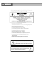
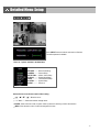
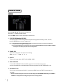
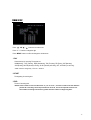
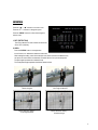
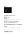
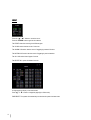
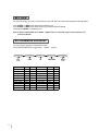
Intelligent & Multiplex
4 CH MPEG-2 DVS
500 V1.2
WARNING
All the safety and operating instructions should be read before operation.
The improper operation may cause permanent damage.
• This adaptor is only for this machine.
Do not use it for other electronic products or it will damage other products.
• Please lift and place this equipment gently.
• Do not expose this equipment to direct sunlight.
• Do not use this equipment near water or in contact with water.
• Do not spill liquid of any kind on the equipment.
• Please power down the unit before unplugging.
• Do not block the ventilation holes at the top and bottom of the unit.
• Do not switch the Power On & Off within short period of time
(within 3 seconds).
• Installation should be made by qualified service personnel.
The lightning flash with arrowhead symbol, within an equilateral
triangle, is intended to alert the user to the presence of uninsulated
"dangerous voltage" within the product's enclosure that may be of
sufficient magnitude to constitute a risk of electric shock to persons.
The exclamation point within an equilateral triangle is intended to alert the
user to the presence of important operating and maintenance-(servicing)
instructions in the literature accompanying the appliance.
TABLE OF CONTENTS
1. What do you get ?
FEATURES
1
PACKAGE CONTENT
1
2. Before Operation
INSTALLATION GUIDE
2
FRONT PANEL
3
REAR PANEL
5
3. Basic Operation
GETTING STARTED
OPERATION
6
7
RECORDING
7
PLAYBACK
8
4. Detailed Menu Setup
MAIN MENU
10
MENU OPTIONS
11
RECORD
11
TIMER SETUP
12
CAMERA
13
DETECTION
14
DISPLAY
15
PIP OPTION
17
DWELL SETUP
18
USER
19
SYSTEM
20
EVENT
BUZZER SETUP
22
REMOTE SETUP
23
UPGRADE SETUP
24
25
5. Advanced Operation
OPERATION OPTIONS
26
2X ZOOM
26
VIDEO LOSS
26
SEARCH
27
USB BACKUP
30
KEY LOCK
31
RS-232 PROTOCOL
31
TROUBLE SHOOTING
32
SPECIFICATIONS
33
6. APPENDIX
APPENDIX A – INSTALL THE HDD
34
APPENDIX B – REPLACE THE HDD
34
APPENDIX C – PIN CONFIGURATIONS
35
APPENDIX D – RECORDING SPEED
36
APPENDIX E – NETWORK APPLICATION
38
What do you get ?
FEATURES
PA
•
MPEG-2 compression format
•
USB Backup ( backup files by USB Flash Drive and USB HDD devices).
•
High resolution: 720 X 480 pixels <NTSC> 720 x 576 pixels <PAL>
•
Duplex function (record and playback)
•
Picture-in-Picture (PIP) in live
•
Motion detection function
•
Alarm input & output function
•
Video loss detected on each channel
•
Linear Zoom (2x)
•
Recording rate: Up to 30 frames/sec (NTSC) ; Up to 25 frames/sec (PAL).
•
Support 1 HDD, IDE TYPE
•
Quick multiple search by event / time list
•
Security password protection
PACKAGE CONTENT
Digital Video Recorder
(with HDD cartridge)
Power Adaptor and Cord
Accessories pack
User’s Manual
HDD screws
Warning:
1. Please check the package to make sure that you receive the complete accessories shown above.
2. The adaptor is DC19V 2A. If it is damaged, users can find replacement adaptor locally with this specification.
1
Before Operation
INSTALLATION GUIDE
1. Shown below is an example of connecting the DVR to existing Observation System.
2. Install HDD (The compatible HDD models are listed in the following table).
Please refer to page.34 Appendix A for installation instructions.
Note: 1. The HDD must be installed before turning on the DVR. If HDD is not installed, the DVR would
function as a 4 CH multiplexer.
2. Users need to set the HDD on the Master mode for system detecting.
CPD500
Alarm
Sensor
PC
PTZ
Main Monitor
1
2
MAIN
3
4
CALL
Call Monitor
RISK OF ELECTR IC SHOCK
DO NOT OPEN
USB
WARNING
: TO REDUCE THE RISK OF ELECTRIC SHOCK,
DO NOT REMOVE COVER (OR BACK).
NO USER-SERVICEABLE PARTS INSIDE.
REFER SERVICING TO QUALIFIED
SERVICE PERSONNEL.
IN
OUT
EXTERNAL I/O
DC 19V
Camera1-4
USB Flash Drive
Backup
Regular
CCD Cam.
Dome
Cam.
Dome
Cam.
Vari-Focal
Co me Cam.
Mini.
Cam.
Bu llet
Cam.
IR
Cam.
Outdoor
Cam.
Power
COMPATIBLE HARD DISK MODELS
Manufacturer
Capacity
Rotation
Deskstar 180 GXP (120 GB)
Deskstar 7K250, HDS722516VLAT20
Deskstar 7K250, HDS722525VLAT80
120GB
160GB
250GB
7200 rpm
7200 rpm
7200 rpm
Deskstar 120GXP (80GB)
80GB
7200 rpm
IBM
Maxtor
Maxtor
Deskstar 120GXP (120GB)
DiamondMax 536DX(60GB) 4W060H4
DiamondMax Plus 9
120GB
60GB
80GB
7200 rpm
5400 rpm
7200 rpm
Maxtor
Maxtor
Maxtor
Seagate
Seagate
Seagate
DiamondMax Plus 9, Model#6Y120L
DiamondMax Plus 9, Model#6Y160L0
120GB
160GB
250GB
80GB
120GB
160GB
7200 rpm
7200 rpm
7200 rpm
7200 rpm
7200 rpm
7200 rpm
Western Digital Caviar WD1200BB-00CAA1
Western Digital Caviar WD2000BB-00DWA0
120GB
200GB
7200 rpm
7200 rpm
Western Digital CaviarSE WD2500JB
250GB
7200 rpm
HITACHI
HITACHI
HITACHI
IBM
Model
MaxLine Plus Ⅱ , Model#7Y250P0
Barracuda ATA IV, ST380021A
Barracuda ATA V, ST3120023A
Barracuda 7200.7 Plus, ST3160023A
NOTE: For non-stop long-time recording, we suggest to have two HDDs for recording to ensure
good reliability of HDD.
2
FRONT PANEL
1. LED LIGHT
The LED Light is ON under following conditions.
•HDD : HDD is reading or recording.
•HDD Full : HDD is full
•ALARM : To turn off the ALARM LED light, please refer to page.15 and
set the ALARM mode as OFF.
•TIMER : When Timer is Enabled
•PLAY : Playing mode
•REC : Recording mode
2. MENU
Press MENU to enter main menu.
3. ENTER
Press ENTER for confirmation
4. SEARCH
Press SEARCH for searching recorded video.
5. ZOOM
Press the ZOOM button Enlarge the picture (2X).
6.
/+ Picture in Picture
PIP: Press “PIP” button for Picture in Picture screen.
+ : Press “+ ” button can change the setting in the menu.
7.
/- 4-channel display mode
: Press “
” button for 4 CH display modes
- : Press “ - ” button can change the setting in the menu.
3
8. SLOW
To slow down the speed of playing mode.
9. FF / ►
•FF : Play video fast forward. (Press FF button again to adjust speed as 3, 45, 600 times)
• ► : Under setup mode, it works as Right button.
10. REW / ◄
•REW : Play video fast backward. (Press REW button again to adjust speed as 15, 90, 600 times)
• ◄ : Under setup mode, it works as Left button.
11. STOP / ▼
•STOP : Under DVR Play mode, it can stop the action.
• ▼ : Under setup mode, it works as Down button.
12. PAUSE / ▲
•Pause : Under DVR play mode, it can pause the action.
• ▲ : Under setup mode, it works as Up button.
13. PLAY
Press PLAY to playback recorded video.
14. REC
Press REC to start recording.
15. CAMERA SELECT (1-4)
Press the Camera Select (1-4) to select the channel.
16. ENTER + SEARCH
Press both “ENTER” + “SEARCH” buttons to enter the USB Backup menu.
17. ENTER + MENU
Key Lock (and Key Unlock).
18. ENTER + ZOOM
PTZ control enable/disable.
4
REAR PANEL
7
1
2
MAIN
3
4
CALL
RISK OF E LEC TR IC S HOCK
DO NOT OP EN
USB
USB PORT
WA R N IN G : TO RE D U C E T HE R IS K OF E L EC TR IC SH OC K ,
D O N OT R E MO VE C OV ER ( OR B AC K ).
NO U SE R -S ER V IC EA BL E PAR TS IN S ID E.
R EF ER S ER V IC IN G TO QU AL IF IED
S ER V ICE P ER S ON N EL .
IN
OU T
EXTERNAL I/O
1
2
DC 19V
3
4
5
1. USB
Connect to a USB HDD or a USB Flash Drive.
2. EXTERNAL I/O
•Controlled remotely by an external device or control system such as Video Web Server or PC.
•Alarm input, external I / O expansion.
3. VIDEO INPUT (1-4)
Connect to video source, such as camera.
4. CALL
Connect to CALL monitor. Show the Switch Display.
When alarm trigger happens, it will change to dwell modes of alarm(refer to p.18)
5. FAN
For ventilation, do not block the opening.
6. POWER
Please use the provided power cord.
7. MAIN
Connect to the main monitor.
Warning:
1. The adaptor is only for this machine. Do not use it for other electronic product or it might damage other products.
2. The adaptor is DC19V 2A. If it is damaged, users can find replacement adaptor locally with this specification.
5
Basic Operation
GETTING STARTED
Before using the DVR, please have a HDD installed ready; otherwise, it will function as a 4 CH multiplexer
(refer to Appendix A and Appendix B for installation or removal of a HDD).
1. Connect the AC power cord and plug into an electrical outlet. The power LED indicator light will be on.
2. It takes approximately 5 to 15seconds to boot the system with the message:”Booting”. The Power LED will turn from
orange to green and Alarm LED will be on.
3. Before operating the DVR, set the system time first. (refer to page 20).
NOTE : 1. If the HDD is not installed correctly or not installed, “NO HDD!”, “HDD KEY UNLOCK!”, “UNKNOWN
FILE SYSTEM! PLEASE FORMAT IT!” messages will appear for 3 seconds, and then return to 4 CH
Multiplexer display mode.
*** “UNKNOWN FILE SYSTEM!”: The format of HDD is not accepted by the DVR system. The system only
accepts EXT3 format. Users can format HDD by selecting “HDD FORMAT” on SYSTEM menu.
2. To switch the system, you need to unplug the AC power, then press “FF” button or “REW” button and connect
the AC power cord, it will switch to NTSC system or PAL system. And the DVR will be auto-detecting.
6
OPERATION
RECORDING
The DVR offers 2 recording modes(Timer, Manual). Under the recording status, if power is off accidentally, the
recorded video will still be stored in the HDD. DVR will return to previous recording setting after power restores.
The first character: ( Frame/Sec)
A : 30 <NTSC> 25 <PAL>
B : 15 <NTSC> 12 <PAL>
C : 5 <NTSC> 4 <PAL>
The second character: (Record Quality)
a : Best b : High c :Normal d : Basic
007.2 GB: the available space of HDD is
O/W: HDD is overwritten
NOTE : Under O/W Recording mode, previously recorded files will be automatically overwritten.
There are two recording modes: Timer and Manual Recording.
1. TIMER RECORDING
Recording is scheduled by a Timer. It will be indicated by the symbol
.
2. MANUAL RECORDING
Recording is initiated manually by pressing the REC button. Symbol
will be shown.
If the system is shut down, the system will resume recording automatically.
Note: To prolong the life span of HDD, please confirm that the power of the machine is off before
unplugging the power cord. Moreover, if the power system is unstable, we suggest installing
UPS .
7
PLAY BACK
Press the “PLAY” button to display the last video.
The screen will display the last video of a channel which is in display.
When all channels are on screen display, and users press the “PLAY” button, the menu (PLAY MODE) will
show up for users to select channels.
When changing the channels, users can either press the buttons “1- 4” on the front panel or enter the “PLAY
MODE”menu for displaying.
Press “ENTER” button to enlarge the video to full screen.
8
1. FF (FAST FORWARD) & REW (FAST REWIND)
Increase the speed of Fast Forward and Rewind on the DVR by pressing the “FF” button.
In the Play mode, press “ FF ” once to get 3X speed forward and press twice to get 45X speed, and
the maximum speed can reach 600X.
Press “REW ” once to get 15X speed rewind and press twice to get 90X speed, and the maximum
speed can reach 600X.
2. SLOW FORWARD
Slow down the speed of Forward on the DVR by pressing the “SLOW” button.
In the Play mode, press the “SLOW” button to enter the Slow mode.
Press ” SLOW ” once to get 1/4X speed forward and press “ SLOW ” to get 1/8 speed,… and the
slowest speed can reach 1/16X.
3. PAUSE
The still image will be displayed on the screen. (Please refer to page.11 for “STOP RECORD”.)
4. STOP
Press “STOP” button to stop displaying a video.
5. IMAGE JOG DIAL
It will allow you to manually view video frame-by-frame, one image at a time.
In PLAY mode, press “PAUSE ”, it will let the video pause.
Press “ ► ” button advances one image.
Press “ ◄ ” button moves back one image.
9
Detailed Menu Setup
MAIN MENU
Press “MENU” button to enter the main menu at first time.
The default password is 000000.
There are 7 options available in the Main Menu.
RECORD -------- Record Scheduling
CAMERA -------- Camera Setup
DETECTION ---- Motion / Alarm Setup
DISPLAY -------- Display Mode Setup
USER ------------ User Password Setup
SYSTEM -------- System Setup
EVENT ---------- Event List
Outlined below are the buttons used for Menu setting :
▲
” “ ” : Move the cursor.
▲
•“▲” “▼” “
• “ + ” and “ - ” : Select the numbers/ change values.
•ENTER : Enter a submenu mode / an option under a submenu for browsing / Confirm the selection.
•MENU : Enter the menu mode / Confirm the change/ Exit a menu.
10
MAIN OPTIONS
▼
Press the “▲” “▼” “ ” “
▼
RECORD
” buttons to move the cursor.
Press the “+” “-” buttons to change the digit.
Press the “MENU” button to confirm the changes/ to exit the menu.
1. STOP RECORD(MANUAL RECORD)
The system will stop manual recording function during the recording period if the setting is “YES”. And then,
press the “ENTER” button to save the changed value.
Note: 1. The users have to stop recording function on this menu because the users cannot stop it by pressing any
front-panel buttons during the recording period.
2. In the Timer Recording mode, users have to either change the RECORD METHOD setting from TIMER to MANUAL
or change the timer setting to stop the timer recording function.
2. FRAME / SEC
Select the recording speed. The options are as following :
NTSC-30、15 、 5 PAL-25、12 、4
3. QUALITY
There are four image qualities : BEST, HIGH, NORMAL, BASIC.
4. HDD OVERWRITE
To set the HDD OVERWRITE. When the HDD is going to be full under O/W recording mode,
previous recorded files will be overwritten without further warning notices if the HDD OVERWRITE is “ON”.
5. RECORD METHOD
There are two recording methods: MANUAL ( by pressing the “REC” button) and TIMER ( by setting the timer
recording).
***On the Timer Recording mode, users have to either change the RECORD METHOD setting from TIMER to
MANUAL or change the timer setting to stop the timer recording function.
11
▼
Press “▲” “▼” “ ” “
▼
TIMER SETUP
” buttons to move the cursor.
Press “+” “-” buttons to change the digit.
Press “MENU” button to confirm the changes/ to exit the menu.
1. DAY
Choose the day for recording. The options are:
MON(Monday) , TUE (Tuesday), WED (Wednesday), THU (Thursday), FRI (Friday), SAT (Saturday),
SUN (Sunday), MO-FR (Monday to Friday), SA-SU (Saturday to Sunday), OFF, and DAILY(on each day).
* Date could be changed by “+” and “-” buttons.
2. START
The beginning of recording time.
3. END
The end of recording time.
NOTE: If users want to record a video from 11 p.m. to 2 a.m. , and users need to set two different
periods for recording. The first period will be 23 to 24, the second period will be 0 to 2.
The number of ending time must be greater than the number of beginning time.
12
CAMERA
▼
▼
Press the “ ” “ ” buttons to move the cursor.
Press the “+” “-” buttons to change the option/digit.
Press the “MENU” button to confirm the changes/ to exit the menu.
1. TITLE
Assign a title to each channel. The default title is the camera’s number (Up to 8 characters).
2. REC (RECORD)
Select a channel to record.
ON : when the timer input is triggered, DVR will record a video.
OFF : DVR will not record.
3. BR (BRIGHTNESS)
Adjust the brightness of each channel. The level is from 0 to 63.
4. CT (CONTRAST)
Adjust the contrast of each channel. The level is from 0 to 63.
5. CL (COLOR)
Adjust the color of each channel. The level is from 0 to 63.
6. HUE (HUE)
Adjust the hue of each channel. The level is from 0 to 63.
7. CAMERA DEFAULT
The setting of BR/CT/CL/HUE will go back to the default value, which is 31, when users press”camera
default”.
13
DETECTION
Press the “▲” “ ▼ ” buttons to move the cursor.
Press the “+” “-” buttons to change the option.
Press the “MENU” button to confirm the changes/ to
exit the menu.
1. DET (DETECTION)
The motion detection on each channel can be turned
ON or OFF individually.
2. AREA
Press the “ENTER” button to set target-area.
In this function, it is defaulted to detect the whole area.
After entering the setting, users will see the pink area, which means the undetected area,
and users can set the area to be detected, and which will turn from pink to transparent.
The Pink target represents the undetected area.
The Transparent target represents the Motion Detection Area.
The beginning of Motion Detection SettingDetect all targets
Motion Detection Setting –
A row-target detected
Motion Detection SettingOne Target undetected
Motion Detection Setting –
A detected target
14
: navigates between targets.
▼
▼
▲▼
- : turns all targets on the screen ON/ OFF.
+ : press once to set a motion target, press twice to set a row of motion target.
3. LS (Level Sensitivity)
Comparing the difference between two images to allow the system to start motion detection function.
Lower number = higher sensitivity for motion detection. The highest sensitivity setting is 0,
the lowest sensitivity setting is 15. The default value is 06.
4. SS (Spatial Sensitivity)
Set the number of motion detection targets (from 1-99 target areas). The highest sensitivity setting is 0, the
lowest sensitivity setting is 15. The default setting is 01.
Note:The setting of Spatial Sensitivity cannot be more than the number of targets set in the AREA.
5. TS (Temporal Sensitivity)
The system will start the motion detection function if the continuous fields are all different.
The highest sensitivity setting is 0, the lowest sensitivity setting is 15. The default setting is 01.
6. RE (Reference)
Set the Reference image to which the current screen is compared (from 0-63).
For example, the value 8 would compare the current image to the 8th previous image. The higher
value will increase the sensitivity. The default value is 10.
7. ALARM
Select LOW / OFF / HIGH for alarm polarity. The default alarm value is OFF.
8. EVENT DURATION
Set the event duration time.
9.DAY. START. END of Detection
Choose the day for recording, the beginning of recording time and the end of recording time.
Note: When the motion detection function is triggered during the recording period. The symbol will be shown
When the alarm function is triggered during the recording period. The symbol will be shown
.
15
.
DISPLAY
▼
▼
Press the “▲” “ ▼ ” “ ” “ ” buttons to move the cursor.
Press the “+” “-” buttons to change the option/digit.
Press the “MENU” button to confirm the changes/ to exit the menu.
1. TITLE DISPLAY
Set the title shown on monitor.
1
2. OSD COLOR
Select the OSD (On Screen Display) color. The options are WHITE, RED, YELLOW, CYAN, BLUE,
PINK, GRAY, ORANGE.
3. CURSOR COLOR
Select the cursor color. The options are RED, YELLOW, GREEN, CYAN, BLUE, PINK,
GRAY, ORANGE .
NOTE: The setting of OSD COLOR and CURSOR COLOR cannot be the same.
4. LOSS SCREEN
Select a way to display the screen when the video input is out of order. The options are BLACK, BLUE
and RETAIN (retain the last picture).
5. OSD POSITION
Select the OSD POSITION. The options are NORMAL (in upper right corner) or CENTER.
6.PLAYBACK METHOD
Select a video type to playback. The options are frame and field. 1 frame equals two fields.
7. PIP OPTION / DWELL OPTION(see p.17,18)
To enter the PIP setting menu/DWELL setting menu.
16
PIP OPTION
Press the “▲” “▼” buttons to move the cursor.
Press the “+” “-” buttons to change the option.
Press the “MENU” button to confirm the changes/ to exit the menu.
1. FULL SCREEN
The full screen background picture display.
2. PIP SCREEN
The picture with a 1/9 size screen “insert”.
3. POSITION
There are six position settings : D/L (Down/Left), D/M (Down/Middle), D/R (Down/Right),
U/L (Up/Left), U/M (Up/Middle), U/R (Up/Right).
17
DWELL OPTION
▼
▼
Press the “▲” “▼” “ ” “ ” buttons to move the cursor.
Press the “+” “-” buttons to change the option.
Press the “MENU” button to confirm the changes/ to exit the menu.
1. NORM
To set up the DWELL time period that each channel auto sequentially shows on call
monitor. The level is from 01 to 24 Sec or OFF.
2. ALARM
To set up the DWELL time period when alarm input is triggered.
The level is from 01 to 24 Sec or OFF.
18
USER
▼
▼
Press the “▲” “▼” “ ” “ ” buttons to move the cursor.
Press the “+” “-” buttons to change the option/digit.
Press the “MENU” button to confirm the changes/ to exit the menu.
1. USER
To set up the user’s account for controlling. It allows 7 users setting.
Supervisor – Control all the functions.
Other Users – View all functions except the
menu setting and event list
cleaning.
2. PASSWORD
To set the security password for each account.
The maximum length of user’s password is 6 digits.
19
SYSTEM
” “ ” buttons to move the cursor.
▼
▼
Press the “▲” “▼” “
Press the “+” “-”buttons to change the setting
Press the “MENU” button to confirm the changes/ to exit the menu
1. KEY MUTE
To set the KEY MUTE. When the setting is “ON”, there will be no sound when you press any key.
2. BUZZER (see p.22)
To enter the buzzer setup menu.
3. MESSAGE LATCH
The default setting of messages displaying is 10 seconds when the setting is “ON”.
4. DATE DISPLAY
Set the date display. The options are Y/M/D, D/M/Y, M/D/Y and OFF.
5. DATE
Set the date.
6. TIME
Set time.
7. HDD FORMAT
Format HDD by selecting “FORMATE” option. After formating the HDD, the system will restart.
Note:1.The system will take about 12minutes to format 80GB HDD.
If the HDD have been formatted before, it takes about 4 minutes to format it.
2.After formatting the HDD, you would find that the space about 12% is occupied.
20
8. SYSTEM RESET
Reset all system settings back to factory default setting.
9. LANGUAGE
Select one language for menu displaying. The options are ENGLISH and CHINESE. The system will
automatically save the setting.
10. UPGRADE(see p.24)
To enter the upgrade setup menu.
11. REMOTE(see p.23)
To enter the remote setup menu.
21
BUZZER SETUP
1. BUZZER
Set the BUZZER “ON”, it will buzz when event occurs.
2. EXT ALARM
To set the EXT ALARM. It will be trigged by event occurrence when the setting is “ON”.
3. VLOSS ALARM
To set the VLOSS ALARM. When the setting is “ON”, the alarm will start after setting
Buzzer, EXT Alarm or Alarm Duration.
4. MOTION ALARM
To set the MOTION ALARM. When the setting is “ON”, the alarm will start after setting
Buzzer and EXT Alarm.
22
REMOTE SETUP
Press the “▲” “▼” buttons to move the cursor.
Press the “+” “-” buttons to change the option.
Press the “MENU” button to confirm the changes/ to exit the menu.
1. REMOTE MODE
Set the remote mode for connection with computer via RS-232 or RS-485.
(refer to page. 30 for RS-232 & RS-485 Remote Control).
2. BAUD RATE
Set the remote protocol transmitting baud rate. Available options are
115200, 57600, 19200, 9600, 4800, 2400, 1200.
3. ID
To control different DVR by setting remote protocol. ID number can be set from 000 to 254.
23
UPGRADE SETUP
User can upgrade the DVR software by USB storage device.
YES: Upgrade
No : Cancel
It will take few minutes to upgrade the whole system. Users cannot unplug the power cord, or turn off the
power during the period of upgrading.
It will reset the system setting will be disable when the system is upgraded.
Therefore, the users have to reset all settings after upgrading.
CHECK CRC: The system will check the firmware status to ensure the quality of system.
24
EVENT
Press the “▲” “▼” buttons to move the cursor.
Press the “ENTER” button to get into the submenu
The EVENT shows the recording list of different types.
The VLOSS section lists the record of video loss.
The ALARM LOG section lists the record of triggering by external I/O alarm.
The MOTION LOG section lists the record of triggering by motion detection.
The ALL LOG section lists all types of records.
The DELETE ALL option will delete all records.
▼
▼
A single page can display 12 recorded events.
Press “ ” or “ ” button to change the pages(Up to 256 records).
PWR RESET: The system will automatically record when the system has been reset.
25
Advanced Operation
OPERATION OPTIONS
2X ZOOM
Press the “ZOOM” button, it displays zoomed picture on main picture and a small inserted window.
The inserted window contains a movable 1/4 view size of the appointed camera. The range is 2X.
2004 MAY-27 [THU] PM 01:45:37
CAMERA01
▼
▼
• Press the “ZOOM” button again to exit the zoom pointer.
• Press Camera 1-4 button to select a channel.
• Press ▲▼
buttons to move the zoom position.
VLOSS (VIDEO LOSS)
The screen will display “ VLOSS” in the center of display picture, if the video input is not connected properly.
26
SEARCH
Press “SEARCH” button to play the recording.
Select a channel for searching a video record.
Press “▲” “▼” buttons to select camera.
Press the “ENTER” button to get into menu/ submenu
Press the “MENU” button to confirm the changes/exit the menu
[SEARCH MODE]
Press the “ENTER” button to get into each submenu.
1. EVENT SEARCH
Display all the videos, which have been motion triggered on the recording mode.
2. TIME SEARCH
Enter a time period for searching a video.
3. LIST ALL
List all video records.
27
1. Select
Enter a period of time for searching a video.
If the users enter an inexistent period, it will show “PRESS MENU KEY TO RETURN”.
After enter the “MENU” button, the screen will go back to the previous screen.
28
Press the “▲” “▼” buttons to select one record.
Press the “ENTER” / “PLAY” buttons to display.
1. Y/M/D
The Month and the Date display(Year/Month/Date).
2. HO:MI:SE
The beginning of recording time(Hour:Minute:Second).
3. MI:SE
The duration of playing time(Minute:Second).
4. TYPE
D1: Multiplex mode (input images of a channel at a time).
29
USB BACKUP
Users may have to format the USB memory device( USB Sticker and USB HDD devices )
by PC before connecting to the DVR.
Press both “ENTER”+ “SEARCH” buttons, enter the USB BACKUP mode.
Users can save files into the USB storage device, and read files by personal computer.
The system will detect the USB storage device automatically. it will show “DETECTING USB DEVICE”
The symbol [ ] shows the available space of the USB storage device.
And press “ENTER”, you can see this screen.
Press “◄” “►” buttons to select a channel or move to the next digit.
Press “+” “-” buttons to change the digit.
Step 1: Choose a certain camera by pressing “◄” “►” buttons.
Step 2: Enter the beginning and the end of time by pressing “+” “-” buttons.
Step 3: Select OK by pressing “ENTER” button (shows the recording space).
Step 4: Select OK again to start to backup a file.
[ ]/[ ]: [ Recording space ] / [ Total available space of the USB memory device ].
NOTE:
1. The USB memory device can only be detected by these three file types:
FAT32 (WINDOWS), EXT3 (LINUX), EXT2 (LINUX)
2. The system will take a few minutes to search if the file is too large.
3. The backup files can only be read by WinDVD and PowerDVD software.
30
KEY LOCK
For advanced security, users can “Lock” the buttons on your DVR. Key-Lock prevents other people from using the system.
Press “ENTER” + “MENU” at the same time to enable Key Lock.
Press “ENTER” + “MENU” at the same time and key in password (Default : 000000),
and then press “ENTER“ to disable Key Lock.
NOTE: To switch to different USER, press “ENTER” + “MENU” buttons to “KEY LOCK” and then enter the different user’s
password to UNLOCK.
RS-232 REMOTE PROTOCOL
You can use the PC keyboard to simulate DVR keypad.
DATA: REMOTE PROTOCOL using 8 bit data、1 start bit、1stop bit
ACT
(FFH)
CØH
ID
FUNCTION
FUNCTION CODE ASCII FUNCTION CODE
KEY_MENU
0x4D
M
KEY_PLAY
0x50
KEY_SEARCH
0x73
s
KEY_DOWN
0x4E
KEY_ENTER
0x0D ENTER
KEY_RIGHT
0x52
KEY_QUAD
0x51
Q
KEY_POWER
0x57
KEY_ZOOM
0x5A
Z
KEY_KEY_LOCK 0x4B
KEY_PIP
0x70
p
KEY_CH1
0x31
KEY_SLOW
0x53
S
KEY_CH2
0x32
KEY_REC
0x72
r
KEY_CH3
0x33
KEY_LEFT
0x4C
L
KEY_CH4
0x34
KEY_UP
0x55
U
31
ASCII
P
N
R
W
K
1
2
3
4
STOP
(7FH)
TROUBLE SHOOTING
When malfunction occurs, it may not be serious and can be corrected easily. The table below describes some typical
problems and their solutions. Please check on them before contacting your DVR dealer.
PROBLEM
SOLUTION
l
Check power cord connections.
l
Confirm that there is power at the outlet.
Not working when pressing any
button
l
l
Check if it is under Key Lock mode.
Press "MENU" & "ENTER" to exit Key Lock mode.
No recorded video
Timer Record enable does not
working
No live video
l
l
Check if the HDD is installed properly.
Check if the Record Enable is set to YES
l
Check camera video cable and connections.
l
Check monitor video cable and connections.
l
Confirm that the camera has power.
l
Check the setting of camera lens.
No power
NTSC & PAL System switch
To switch the system, you need to unplug the AC power, then
press “FF” or “REW”and plug inthe AC power cord
again.(Please refer to page.6)
Under overwritting and duplex
modes, the playback motion is
interrupted
please press “STOP” button and then the “PLAY” button to play
again
32
SPECIFICATIONS
Video Format
Hard Disk Storage
NTSC/EIA or PAL/CCIR
IDE type, UDMA 66, supported a over 250 GB HDD
Resolution
720 x 480 pixels <NTSC> , 720x576 pixels <PAL>
Recording Mode
Camera Input Signal
Manual / Timer
Main Monitor Output
Composite video signal 1 Vp-p 75Ω BNC
Call Monitor Output
Composite video signal 1 Vp-p 75Ω BNC
1 port. Support USB 1.1 Device
USB Interface
Motion Detection Sensitivity
Video Loss Detection
Refresh Rate
Recording Rate
Dwell Time
Picture in Picture
Key Lock
Picture Zoom
Camera Title
Video Adjustable
Alarm Input
Alarm Output
Remote Control
Time Display Format
Power Source
Power Consumption
Operation Temperature
RS-232C / RS-485 (bps)
Dimension (mm)
Net Weight
Composite video signal 1 Vp-p 75Ω BNC, 4 channels
16 Levels
Yes
120 frames/sec. for NTSC / 100 frames/sec. for PAL*
Up to 30 frames/sec. for NTSC / 25 frames/sec. for PAL
Programmable (1~24 Sec)
Yes (Movable)
Yes
2X (Movable)
8 letters
Hue/ Color/ Contrast/ Brightness Adjustable
TTL input, High (5V), Low (GND)
COM./N.O/N.C
RS-232 or RS-485
YY/MM/DD, DD/MM/YY, MM/DD/YY, OFF
DC 19V
<32W
10 ~ 40℃
115200、57600、19200、9600、4800、2400、1200
343(W) x 223(L) x 59(H)
2 kg
• Specifications are subject to change without notice.
*NTSC: 4CH x 30IPS = 120 frames/sec, PAL: 4CH x 25IPS = 100 frames/sec
33
APPENDIX A– INSTALL THE HDD
Follow these steps carefully in order to ensure correct installation.
Fig. 1
Fig. 2
Fig. 3
Fig. 4
Fig. 5
Step 1 Remove the lid and unscrew the screws from HDD bracket module .
Step 2 Insert the HDD into the HDD bracket and screw the four screws. (refer to the Fig. 1, Fig. 2).
Step 3 Connect the HDD power cable to the HDD (refer to the Fig. 3), and attach the HDD
connector to the 40-pin cable,
Step 4 Screw the HDD and the DVR machine together (refer to the Fig. 3).
Step 5 Pull the sides of the lid apart slightly and push the lid down (refer to the Fig. 4).
Note: Do not try to retrieve the HDD data by PC. The video file cannot be read by PC,
operation on PC would damage the FAT table of the hard disk.
APPENDIX B– REPLACE THE HDD
Follow these steps carefully in order to ensure correct installation.
Fig. 1
Fig. 2
Fig. 3
Fig. 4
Fig. 5
Step 1 Remove the lid (refer to the Fig 1).
Step 2 Remove the HDD power cable from the HDD (refer to the Fig. 3).
Step 3 Take out the HDD from DVR machine carefully.
Step 4 Unscrew the four screws connected the hard drive to the bracket and remove the
HDD bracket module. Repeat those steps according to the “Install the HDD” section for
resetting another HDD (refer to the Fig 4).
Step 5 Pull the sides of the lid apart slightly and push the lid down.
Note: When HDD works for a period of time, the surface temperature will be high, please notice it.
34
APPENDIX C– RECORDING SPEED
The Recording Time is different based on Recording Speed, Recording Quality and Recording Mode.
Please refer to the following table. HDD capability is 250GB.
NTSC SYSTEM
IPS
Multiplex
Mode
30
15
5
Best
106hr
212hr
636hr
High
132hr
264hr
792hr
Normal
213hr
426hr
1278hr
Basic
326hr
652hr
1956hr
HDD Type
250 GB
PAL SYSTEM
IPS
Multiplex
Mode
HDD Type
35
25
12
4
Best
106hr
212hr
636hr
High
132hr
264hr
792hr
Normal
213hr
426hr
1278hr
Basic
326hr
652hr
1956hr
250 GB
APPENDIX D– PIN CONFIGURATIONS
15 pin com port
•
•
DVR
•
•
9 pin com port
•
•
DVR
DQR
•
•
36
PIN 1. RS232-TX : RS-232
DVR can be controlled remotely by an external device or control system, such as a control keyboard, using RS232 serial communications signals.
PIN 2. RS232-RX : RS-232
DVR can be controlled remotely by an external device or control system, such as a control keyboard, using RS232 serial communications signals.
PIN 3, 4, 5, 6 ALARM INPUT
To connect wire from ALARM INPUT (PIN 3, 4, 5, 6) to GND ( PIN 9 ) connector.When alarm has been triggered,
signal becomes “Low”, and it will stop all alarm activities. Under normal operation, signal remains “High”.
PIN 7. EXTERNAL ALARM NC
Under normal operation COM connect with NC and disconnect from NO. But when alarm is triggered, COM
disconnect with NC, and connect with NO.
PIN 8. EXTERNAL ALARM NO
Under normal operation, COM will disconnect from NO. But when Alarm is triggered, COM will connect with NO.
PIN 9. GND
GROUND
PIN 10. RS485-B
DVR can be controlled remotely by an external device or control system, such as a control keyboard, using RS485 serial communications signals.
PIN 11. RS485-A
DVR can be controlled remotely by an external device or control system, such as a control keyboard, using RS485 serial communications signals.
PIN 14. ALARM RESET (INPUT)
To connect wire from ALARM RESET ( PIN 14 ) to GND ( PIN 9 ) connector, it can disable ALARM. An external
signal to ALARM RESET ( PIN 14 ) can be used to reset both ALARM OUTPUT signal and DVR’s internal buzzer.
When alarm has been triggered, signal becomes “Low”, and it will stop all alarm activities. Under normal operation,
signal remains “High”.
PIN 15. EXTERNAL ALARM COM
Under normal operation COM connect with NC and disconnect from NO. But when alarm is triggered, COM
disconnect from NC, and connect with NO.
37
APPENDIX E– NETWORK APPLICATION
Video Web Server Features
• Compatible with most of CCTV Products; empower any video output device watching and
controlling on the Internet or LAN
• Auto Network Reconnection (ANR)
• Upgrade firmware & AP from FTP site via Video Web Server
• Support Watch dog function
• Support Dynamic IP address via a router.
• Support 4 alarm inputs
• Duplex function, record and playback simultaneously at client site
• Auto e-mail warning system which will remind you if external alarm
happens
• Intelligent non-stoppable recording function after ANR
Video Web Server
• Support Multi AP screens Unique video player
• Alarm trigger recording function.
DVR Control
Video Web Server
1 ) Connect the Sub-D plug of Video Web
Server with our own brand DVR products.
GND
ALARM
INPUT1
4CH DVR
NORMAL NORMAL
LOW
HIGH
RS485-A
ALARM
INPUT2
RS485-B
ALARM ALARM
INPUT3 INPUT4
RS232-TX
GND
RS232-RX
RE485-B
ALARM INPUT1
RS485-A
ALARM INPUT2
DISK FULL
ALARM INPUT3
REC START
ALARM INPUT4
ALARM RESET
EXTERMAL ALARM NC
EXTERNAL ALARM COM
EXTERNAL ALARM NO
2 ) Set the “Remote” function in the DVR
products.
NOTE : Remote mode : RS-485,
Baud rate : 2400, ID : same
as “I/O port setting” in the Video
Web Server.
3 ) Set the “I/O Port Setting” in the system
config of Video Web Server.
Port1 : 4CH DVR, Device ID : 001.
38