1
f
Save
For
This
Future
lVlanuai
Reference
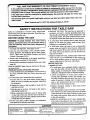
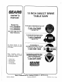
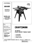
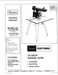
Model 113.226880
Model No.
113,226880
1!3.298090
l
Saw With
/
/
Legs And
Two Table
Extensions
!
Model 113,298090
L
L
I
. . 6/CRRFTSMRN
Serial
Number
Model
and
serial
may be found
the base.
numbers
10 INCH
DIRECT DRIVE
TABLE SAW
at the rear of
You should record both model
and serial number in a safe
place for future use.
JJ
YOUR
SAFETY
• assembly
=operating
- repair parts
READ ALL
INSTRUCTIONS
CAREFULLY
.J
%_,=,
Sears,
Part No, SP 5509
Roebuck
_.
and Co., Hoffman
Estates,
iL. 60179
U.S.A.
Printed in U.S.A.
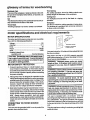
will repair it, free of charge. This warranty appUesonly while this product is in the United States.
If this table saw is used for commercial or rental purposes, this warranty wig apply for ninety days
/
from the date of purchase.
This warranty gives you specific legal rights, and you may also have other rights which vary from
state to state.
Sears, Roebuck and Co., D817 WA, Hoffman Estates, IL. 60179
SAFETY INSTRUCT|ONS
Safety is a combination of common sense, staying alert
and knowing how your table saw works. Read this manual to understand this saw.
I
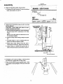
1. Assembly and Alignment. (See pages 12-31 )
2.Learn the use and function of the ON-OFF Switch,
Guard, Spreader, Anti-Kickback devise, Miter Gauge,
Fence, Table Insert and Blade Elevation and Bevel
Controls. (See pages 32-34)
3. Review and understanding of all safety instructions
and operating procedures in this manual.
4. Review of the maintenance methods for this saw. (See
page 46)
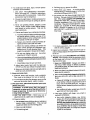
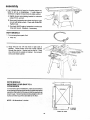
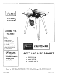
Read the DANGER label found on the front of the saw,
as shown below.
WHEN INSTALLING OR MOVING THE SAW
1. AVOID DANGEROUS EQUIPMENT. Use the saw in a
FOR TABLE SAW
5.To avoid injury form electrical shock, make sure your
fingers do not touch the plug's metal prongs when
plugging in or unplugging the saw.
6.To avoid back injury, get help or use recommended
casters when you need to move the saw. Always get
help if you need to lift the saw. Hold the saw close to
your body. Bend your knees so you can lift with your
legs, not your back.
7. NEVER STAND ON TOOL. Serious injury could occur
if the tool tips or you accidentally hit the cutting toolj
Do not store anything above or near the tool wher4
anyone might stand on the tool to reach them.
BEFORE EACH USE:
1. inspect your saw
A.To avoid injury from accidental starting, unplug the
saw, turn the switch off and remove the switch key
before raising or removing the Guard, changing the
dry place protected from rain. Keep work area well
D.When using table extensions over 24 inches wide
on any side of the saw, bolt the saw to the floor or
prop up the outer end of the extension from the floor
to keepthe saw from tipping.
cuttingtoo, changingthe setup or adjusting anything.
B. Check for alignment of moving parts, binding of
moving parts, breakage of parts, saw stability, and
any other conditions that may affect the way the saw
works. If any part is missing, bent or broken in any
way, or any electrical part does not work properly,
turn the saw off and unplug the saw.
C.Reptace damaged, missing or failed parts before
using the saw again.
D.Use the Sawblade Guard, Spreader and Anti-Kickback Pawls for any thru-sawing (whenever the blade
comes through the top of the workpiece). Make sure
the Pawls work properly. Make sure the Spreader is
in line with sawblade.
E.REMOVE ADJUSTING KEYS AND WRENCHES.
3. Put the saw where neither Operator nor bystanders
must stand in line with the saw blade,
Form habit of checking for and removing keys and
adjusting wrenches from tool before turning it on.
lighted.
2.To avoid injury from unexpected saw movement:
A.Put the saw on a firm level surface where there is
plenty of room for handling and properly supporting
the workpiece.
B.Support the saw so that the table is level and the
saw does not rock.
C.Bolt the saw to the floor it it tends to slip, walk or
slide during nomnal use.
I
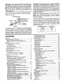
_DANGER
1 Read manual before using
|2,Wear
|
J
4.GROUND THE SAW- This saw has an approved 3conductor cord and a 3-prong grounding type plug.
The plug fits grounding type outlets designed for 120
volt 15 amp circuits.The green conductor in the cord is
the NEVER connect the green wire to a live terminal.
BEFORE USING THE SAW
WARNING: To avoid mistakes that could cause_
serious, permanent injury, do not plug the saw in
until the following steps have been satisfactorily
completed.
|
saw.
safety goggles that meat
ANSI Z87.1 standerds.
3.Do not reach around or over saw
blades,
4.Keep bade
guard
down and in
place for through cuts.
5,Do not do freshand cuts.
6,Kesp hands out of path of saw
blade,
7.When
tipping,
use push stick when
9.When
fence is set 2 inches or more from
blade,
8.Kncw how to reduce the risk of
kickback, See instrustions for ripping,
2
ripping, use push
blodk and
10.'Turn
power
auxiliary fence when fence is set
to stop before
between l/2 and 2 inches from
blade. Do not make rip cuts
servicing,
narrower than 1/2 inch.
off and wait for blade |
adjusting
or
!
/
F.To avoidinjuryfromjams,slipsorthrownpieces
(kickbackandthrowback):
1. USE ONLY"RECOMMENDED
ACCESSORIES"(Seepage47). Followthe instructions
thatcomewiththe accessories.Usingother
accessories
maybedangerous.
2. Choose
therightbladeor cuttingaccessory
for
thematerialandthetypeofcuttingyouplanto
do.
3. Neveruse grindingwheels, abrasive cut-off
.
Roll long sleeves above the elbow.
5. Noise levels vary widely.
To avoid possible
hearing damage, wear ear plugs or muffs when
using saw for long periods of time.
.
wheels, friction wheels (metal slitting blades)
wire wheels or buffing wheels. They can fly
apart explosively.
4. Choose and inspect your cutting tool carefully.
Any power saw can throw foreign objects into
the eyes. This can cause permanent eye damage. Wear safety goggles (not glasses) that
comply with ANSI Z87.1 (shown on package).
Everyday eyeglasses have only impact resistant lenses. They are not safety glasses. Safety
goggles are available at Sears retail catalog
stores. Glasses or goggles not in compliance
with ANSI Z87.1 could seriously hurt you when
they break.
a. To avoid cutting tool failure and thrown shrapnel (broken pieces of blade), use only 10" or
smaller blades or other cutting tools marked
for speeds of 3450 rpm or higher.
WEAR
YOUR
b. Always use unbroken, balanced blades designed to fit this saw's 5/8 inch arbor.
c. When thru-sawing (making cuts where the
blade comes through the workpiece top),
always use a 10 inch diameter blade. This
keeps the spreader in closest to the blade.
7. For dusty operations, wear a dust mask along
with the safety goggles.
Use arbor
C. Inspect your workpiece.
Make sure there are no
nails or foreign objects in the part of the workpiece
to be cut.
e. Use only sharp blades with properly set teeth.
Consult a professional blade sharpenerwhen
in doubt.
D. Plan your cut to avoid KICKBACKS and THROWBACKS - when a part or all of the workpiece binds
on the blade and is thrown violently back toward
the front of the saw.
d. Do not over tighten arbor nut.
wrenches to "snug" it securely.
f. Keep blades clean of gum and resin.
5. Adjust table inserts flush with the table top.
NEVER use the saw without the proper insert.
6. Make sure all clamps and locks are tight and no
parts have any excessive play.
2. Keep work area clean
A. Cluttered areas and benches invite accidents.
Floor must not be slippery from wax or sawdust.
B. To avoid burns or other fire damage, never use the
saw near flammable liquids, vapors or gases.
3. Plan your work - plan ahead to protect your eyes,
hands, face, ears.
WARNING: To avoid injury, don't do layout,
assembly, or setup work on the table while the
blade is spinning. It could cut or throw anything hitting the blade.
A. USE THE RIGHT TOOL - Don't force tool or
attachment to do a job it was not designed for.
.
Never cut FREEHAND:
Always use either a
Rip Fence, Miter Gauge or fixture to position
and guide the work, so itwon't twist, bind on the
blade and kickback.
2. Make sure there's no debris between the workpiece and its supports.
3. When cutting irregularlyshaped
workpieces,
plan your work so it will not slip and pinch the
blade:
a. A piece of molding, for example, must lie flat
or be held by a fixture or jig that will not let it
twist, rock or slip while being cut. Use jigs or
fixtures where needed to prevent workpiece
shifting.
b. Use a different, better suited type of tool for
work that can't be made stable.
4. Use extra caution with large, very small or
awkward workpieces:
a.
B. Dress for safety:
1. Do not wear loose clothing, gloves, neckties or
jewelry (rings, wristwatches). They can get
caught and draw you into moving parts.
2. Wear non-slip footwear.
3. Tie back long hair.
Use extra supports (tables, saw horses,
blocks, etc.) for anyworkpieces large enough
to tip when not held down to the table top.
NEVER use another person as a substitute
for atable extension, or as additional support
for a workpiece that is longer or wider than
the basic saw table, or to help feed, support
or pull the workpiece.
safety instructions for table saw
4. KEEP CHILDREN AWAY. All visitors should be kept
asafe distance fromwork. Make sure bystanders are
clear of the saw and workpiece.
b. Never confine the piece being cut off, that is,
the piece NOT against the fence, mitergauge
or fixture. Never hold it, clamp it. touch it, or
use length stops against it. it must be free to
move. If confined, itcouldgetwedged against
the blade and cause a kickback or throwback.
5, Let the blade reach full speed before cutting.
6. DON'T FORCE TOOL. It will do the job better and
safer at its designed rate. Feedthe workpiece intothe
blade only fast enough to let it cut without bogging
down or binding.
c. Never cut more than one workpiece at a time.
d. Never turn your table saw"ON" before clear°
ing everything except the workpiece and
related support devices off the table.
7. Before freeing any jammed materiah
A. Turn switch "OFF".
B. Unplug the saw.
4. Plan the way you wil! push the workplece throug h
C. Wait for all moving parts to stop.
A NEVER pull the workpiece through. Start and
finish the cut from the front of the tabb saw.
D. Check blade, Spreader and Fence for proper alignment before starting, again.
B. NEVER put your fingers or hands in the path of
the sawblade or other cuthng tool.
8. To avoid throwback of cut off p_eces:
A Use the Guard assembly.
C. NEVER reach in back of the cutting toolwith either
hand to hold down or support the workpiece,
remove wood scraps, or for any other reason.
B. To remove loose pieces beneath or trapped inside
the guard:
1. Turn saw "OFF".
D Avoid hand positions where a sudden slip could
cause fingers or hand to move into a sawblade or
other oJtting tool,
E. DON'T OVERREACH.
and balance.
2. Remove switch key
3. Wait for blade to stop before lifting the Guard.
Always keep good footing
ADDITIONAL
_NSTRUCTIONS
FOR
RiP TYPE CUTS
F. Push the workpiece against the rotation of the
blade, NEVER feed material into the cutting tool
from the rear of the saw.
1. NEVER use the Miter Gauge when ripping.
2 Use a Push Stick whenever the fence is 2 or more
inches from the blade. When thru-sawing, use an
Auxiliary Fence and Push Block whenever the Fence
must bebelween 1/2 and 2 inchesof the blade. Never
thru-saw rip cuts narrower than t/2 inch
(See
'_ASIC SAW OPERATION - USING THE RIP FENCE"
section.)
G Always push the workpiece all the way past the
sawblade.
H. As much as possible, keep your face and body to
one side of the sawblade, out of linewith a possible
kickback or throwback.
I NEVER turn the saw"ON"before clearingthetabte
of al! tools wood scraps, etc., except the workpiece and related feed or support devices for the
cut planned.
3. Never rip anything shorter than 10" long.
4. When using a Push Stick or Push Btock, the traiting
end ot the board must be square. A Push Stick or
Block against an uneven end coutd stip off or push the
work away from the Fence.
J, AVOID ACCIDENTAL STARTING - Make sure
switch is "OFF" before plugging saw in.
WHENEVER SAW BLADE iS SPINNING
5, A FEATHERBOARD can help guide the workpiece.
(See "BASIC SAW OPERATION - USING THE RIP
FENCE.") Always use Featherboards for any non
thru rip type cuts.
WARNING: Don't let familiarity (gained from frequent use of your table saw) cause a careless
mistake. Always remember that a careless fraction of a second is enough to cause a severe
injury.
24
1. Before actually cutting with the saw, watch it while it
runs for a short while. If it makes an unfamiliar noise
or vibrates a lot, stop immediately. Turn the saw off,
Unplug the saw. Do not restart until finding and fixing
the problem.
S/16"
_i
APART
BEFORE STARTING
2. Make sure the top of the arbor or cutting tool turns
toward the front of the saw.
1. To avoid kickbacks and slips into the blade, make
sure the Rip Fence is parallel to the sawblade.
3. Set the cutting tool as low as possible for the cut
you're planning.
4
2_ Before thru-sawing, check the AntioKickback Pawls.
(See "BASIC SAW OPERATION - USING THE RIP
FENCE.") The Pawls must stop a kickback once it
has started Replace or stlarpen Anti-Kickback Pawls
when points become duti.
3. Plastic and composition (like hardboard) materials
may be cut on your saw However, since these are
usually quite hard and slippery, the Anti-Kickback
Pawls may not stop a kickback. Therefore, be especially careful in your set-up and cutting procedures
WHILE CUTTING
1. To avoid kickbacks and slips into the blade, always
push forward on the section of the workpiece between
the saw blade and the Rip Fence. Never push forward
on the piece being cut off.
ADDITIONAL
CROSS
INSTRUCTOONS
CUT TYPE
FOR
CUTS
BEFORE STARTING
1. NEVER use the Rip Fence when crosscutting.
2. An auxiliary wood facing attached [o the Miter Gauge
can help prevent workpiece twisting and throwbacks
glossary
Attach it to the holes provided. Make the facing iong
enough and big enough to support your work. Make
sure, however, it witl not interfere with the Sawbfade
Guard..
3. Use jigs or fixtures to help hold any piece too sina!! to
extend across the full length of the Miter Gauge face
during the cut. This lets you properly hold the Miter
Gauge and workpiece and helps keep your hands
away from the blade. (See page 32,)
WHILE CUTTING
1. To avoid blade contact, always hold the Miter Gauge
as shown in "BASIC SAW OPERATIONS
- USING
THE MITER GAUGE,"
BEFORE
LEAVING
THE SAW
1_ Turn the saw off.
2. Wait for blade to stop spinning.
3. Make workshop child-proof. Lock the shop Disconnect master switches. Remove the yetlow Switch
Key. Store it away from children and others not
qualified to use the too!.
4
Unplug the saw
of terms for woodworking
Anti-Kickback Pawls (AKP)
Device which, when properly maintained, is designed to
stop the workpiece from being kicked back at the operator during ripping operation.
Kickback
An uncontrolled grabbing and throwing
back toward the front of the saw.
of the workpiece
Arbor
The shaft on which a cutting tool is mounted,
Leading End
The end of the workpiece which, during a rip type
operation, is pushed into the cutting tool first.
Crosscut
A cutting or shaping operation made across the width of
the workpiece.
Molding
A non through cut which produces a special shape in the
workpiece used for joining or decoration.
Dado
A non through cut which produces a square sided notch
or trough in the workpiece.
Push Stick
A device used to feed the workpiece through the saw
during narrow ripping type operations and helps keep
the operator's hands well away trom the blade.
Featherboard
A device which can help guide workpieces during rip
type operation.
Freehand
Performing a cut without using a Fence, Miter Gauge,
fixture, hold down or other proper device to keep the
workpiece from twisting during the cut.
Gum
A sticky, sap based residue from wood products.
Heel
Misalignment of the blade.
Kerr
The amount of material removed by the blade in a
through cut or the slot produced by the blade in a non
through or partial cut.
Push Block
A device used for ripping type operations too narrow to
allow use of a Push Stick.
Rabbet
A notch in the edge of a workpiece.
Resin
A sticky, sap base substance that has hardened.
Ripping
A cutting operation along the length of the workpiece.
Revolutions Per Minute (RPM)
The number of turns completed by a spinning object in
one minute.
glossary of terms for woodworking
Sawblade Path
The area of the workpiece or table top directly in line with
the part of the workpiece which will be, or has been, cut
by the blade.
Set
The distance that the tip ofthe sawblade tooth is bent (or
set) outward from the face of the blade.
Throw-Back
Throwing of pieces in a manner similar to a kickback.
Thru-Sawing
Any cutting operation where the blade extends completely though the thickness of the workpiece.
Trailing End
The workpiece end last cut by the blade in a ripping
operation.
Workplece
The item on which the cutting operation is being done.
The surfaces of a workpiece are commonly referred to
as faces, ends, and edges.
i
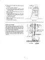
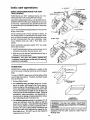
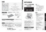
motor specifications and electrical requirements
3oPRONG PLUG
MOTOR SPECiFICATiONS
/t0)
The motor used inthis saw is a relay start, no n-reversible
type, with the following specifications:
Voltage ...............................................................
120
Amperes ...........................................................
11.5
Hertz ....................................................................
60
Phase ...................................................
Single
RPM .................................................................
3450
Rotation (viewed from
sawblade end) ......................... Counterclockwise
CAUTION: The staring relay in this switch housIng is a gravity sensitive type. To avoid damaging
your motor, never turn power on unless the saw
is upright in sawing position,
MOTOR
SAFETY
PROTECTION
1. Frequent opening of fuses or circuit breakers may
result if motor is overloaded, or if the motor circuit is
fusedwith a fuse other than those recommended. Do
not use a fuse of greater capacity without consulting
the power company.
2. Although the motor is designed for operation on the
voltage and frequency specified on motor nameplate,
minimal loads will be handled safely at voltages 10%
above or below the nameplate voltage. Heavy loads,
however, require that voltage at motor terminals be
not less than the voltage specified on nameplate.
3- Most motor troubles may be traced to loose or incorrect connections, overloading, reduced input voltage
(which results when small size wires are used in the
supply circuit) orwhen the supply circuit is extremely
long. Always check connection, load and supply
circuitwhen the motor fails to perform satisfactorily.
Check wire sizes and lengths with table at end of this
section.
CONNECTING
OUTLET
TO POWER
SOURCE
This saw must be grounded while in use to protect the
operator from electrical shock.
¢-
\
GROUNDING
PRONG
PROPERLY GROUNDED
3-PRONG OUTLET
Your saw iswired for 120 volts and ithas a plug that looks
like the one shown.
Plug power cord into a 110-120V properly grounded
type outlet protected by a 15 amp. time delay or CircuitSaver fuse or circuit breaker.
WARNING:
Damaged power cords can cause
shock or fires, if the power cord is worn, cut, or
damaged in any way, have it replaced immediately.
WARNING:
Electric shock can kill. Not all outlets
are properly grounded. If you are not sure that
your outlet is properly grounded, have it checked
by a qualified electrician.
WARNING:
To avoid electrical shock, do not J
permit fingers to touch the tenninals of the plug,
when InstalIlng or removing the plug to or from
the outlet.
I
WARNING: Failure to properly ground this power
tool can cause electrocution or serious shock,
particularly when used in damp locations, or near
metal plumbing, if shocked, your reaction could
cause your hands to hit the cutting tooL
This saw is equipped with a 3-conductor cord and
groundingtype plug which been approved by Underwriters' Laboratories. The ground conductor has a green
jacket and is attached to the tool housing at one end and
to the ground prong in the attachment plug at the other
end.
This plug requires a mating 3-conductor grounding type
outlet as shown.
WARNING: To help avoid electric shock, the green
grounding lug extending from the adapter must be
connected to a permanent ground such as to a
properly grounded outlet box. Not all outlet boxes
are properly grounded, if you are not sure the outlet box is properly grounded, have it checked by a
qualified electrician.
planning Avoid
to useelectric
for this shock,
saw is ifof the
the outlet
two prong
j are
WARNING:
you
type, DO NOT REMOVE OR ALTER THE GROUNDING PRONG IN ANY MANNER. Use an adapter, as
shown, and always connect the grounding iug to a
known ground.
It is recommended that you have a qualified electrician
replace the TWO prong outlet with a properly grounded
THREE prong outlet.
NOTE: The adapter illustrated is for use only if you
already have a properly grounded 2-prong receptacle.
NOTE: make sure the proper extension cord is used and
is in good condition.
The use of any extension cord will cause some loss of
power. To keep this to a minimum and to prevent overheating and motor burn-out, use the table below to determine the minimum wire size (A.W.G.) extension cord.
Use only 3 wire extension cords which have 3-prong
grounding type plugs and 3-pole receptacles
which
accept the tool plug.
Grounding Lug
3-Pron-
_
P,o '
/
_==_MakeSureThisis
_
I_11
_--I
Connected to a
",o,,.,'
-'=====_ Receptacle
Adapter
An adapter, as shown, is available for connecting plugs to
2-prong receptacles. The green grounding lug extending
from the adapter must be connected to a permanent
ground such as to a properly grounded outlet box. The
temporary adapter should be used only until a properly
grounded outlet can be installed by a qualified electrician.
.........
I'll
I'1
Extension Cord
Length
Wire Size
A.W.G.
0 - 25 Ft.
26 - 5O Ft.
16
14
ii
contents
Installing Blade Guard .............................................
Adjusting Miter Gauge .............................................
Getting to Know Your Saw ...........................................
On-Off Switch ..........................................................
Elevation Handwheel ...............................................
Tilt Handwheel .........................................................
Rip Fence ................................................................
Miter Gauge .............................................................
Blade Guard ............................................................
Table Insert ..............................................................
Removing and Installing Sawblade .........................
Exact-I-Cut ..............................................................
Basic Saw Operation ...................................................
Work Helpers ...........................................................
Safety Instructions for Basic Saw Operation ...........
Using the Miter Gauge ............................................
Crosscutting ..........................................................
Repetitive Cutting ..................................................
Miter Cutting ..........................................................
Bevel Cutting .........................................................
Compound Miter Cutting .......................................
Using the Rip Fence ................................................
Ripping ..................................................................
Using Featherboards For Thru Sawing
Resawing ..............................................................
Using Featherboards for Non Thru-Sawing ..........
Rabbeting ..............................................................
Ploughing and Molding .........................................
Cutting Panels .......................................................
Dadoing ................................................................
Molding Cutting .....................................................
Motor ...........................................................................
Lubricating and Maintenance ..................................
Maintenance ................................................................
Lubrication ...................................................................
Recommended Accessories ........................................
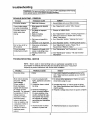
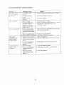
Troubleshooting ...........................................................
General ....................................................................
Motor .......................................................................
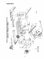
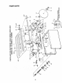
Repair Parts ................................................................
Warranty ..................................................................................
2
Safety Instructions for Table Saw ............................................
2
Additional Instructions for Rip Type Cuts ............................ 4
Additional Instructions for Cross Cut Type Cuts ................. 5
"Glossary ..................................................................................
5
Motor Specifications and Electrical
Requirements ..................................................................
6
Motor Specifications ...........................................................
6
Motor Safety Protection ......................................................
6
Connecting to Power Source Outlet .................................... 6
General Information ................................................................
8
Model Description ...............................................................
8
Unpacking and Checking Contents ......................................... 8
Tools Needed ......................................................................
8
List of Loose Parts (Model 113.226880) ............................. 9
List of Loose Parts (Model 113.298090) ........................... 10
Assembly ...............................................................................
12
Assembly of Steel Leg Set ................................................
12
Mounting Saw to Leg Set (Model 113.226880) ................ 12
Installing Bevel Pointer and Handwheels ......................... 13
Checking and Adjusting Table insert ...............................
14
Heeling Adjustment or Parallelism of Sawblade
to Miter Gauge Groove .................................................
14
Blade Tilt, or Squareness
of Blade to Table ............. 15
Blade Elevations ......................................................
17
Tilt and Elevation Mechanism
..................................
18
Attaching and Assembly Table Extensions
(Model 113.226880) .......................................................
18
Installing Rip Fence Guide Bars and Switch Box
(Model 113.2268801 .......................................................
19
Attaching and Assembling Table Extensions
('Model 113.298090} .......................................................
22
Installing Rip Fence Guide Bars and Switch Box
(Model 113.298090)......................................................
23
Mounting Saw to Leg Set (Model 113.298090) ....... 25
Aligning Table Extensions (Model 113.298090) ....... 25
Mounting Saw to Workbench ................................... 26
Self-Aligning Spring Adjustment .............................. 27
Rip Fence Alignment Adjustment ............................ 28
Adjusting Rip Scale Indicator ................................... 28
7
29
31
32
32
33
33
33
33
33
33
34
34
35
35
36
38
38
39
39
40
40
40
41
43
44
44
45
45
45
45
46
46
46
47
47
48
48
49
50
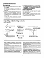
general information
BOTH MODELS
3. Sometimes small parts get lost in packaging materials. Do not throw away any packaging until your saw
is put together. If you are missing a part, check the
packaging before contacting Sears.
1. This manual is for the following Models, 113.226880
or 113.298090.
All sections are labeled with the correct model num-
MODEL
ber. Follow ONLY instructionsthat are meant foryour
model saw.
DESCRIPTUON
Model 113. 226880:10-inch direct drive table saw with
a 20 x 20 inch CAST IRON table and two 10 x 20-inch
CAST IRON extensions.
2. If you are missing any part(s) while putting your saw
together, do not continue assembly. Contact your
Sears Service Center or Retail Store and get the
missing part(s) before continuing assembly or trying
to use the saw.
Model 113. 298090: 10-inch direct drive table saw with
a 20 x 27-inch die cast ALUMINUM table and two 10 x
27-inch STAMPED STEEL extensions,
Complete parts lists are located at the end of this
manual. Use these liststo identify the part number of
any missing part.
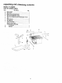
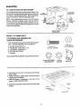
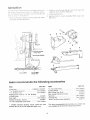
unpacking and checking contents
TOOLS
NEEDED
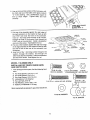
COMBINATION
MediumScrewdriver
SmallScrewdriver
DRAW
BOARD
LIGHT
ALONG
LINE
SQUARE
ON
THIS EDGE.
MUST
BE
TRUE.
STRAIGHT
EDGE
OF BOARD
3/4" THICK.
THIS
EDGE
MUST
BE PERFECTLY
STRAIGHT,
'3",
i
•
#2 Phillips Screwdriver
Pliers
_
"K_
Wrench, Hex "L" 3/16
Wrench, Hex'L" 1/8
I
L_
I
Combination Square
Wrenches
3/8 in. 7/16 in.
1/2 in. 9/16 in.
SHOULD
BE NO GAP OR OVERLAP
HERE WHEN
SQUARE
IS FLIPPED
OVER
IN DOTTED
POSITION.
Model 113.226880 or 113.298090 is shipped complete
in one carton and includes two table extensions, steel
legs and motor.
Remove the protective oil that is applied to the table top
and edges of the table. Use any ordinary household type
grease and spot remover.
Separate all parts from packing materials and check
each one with the illustration and the list of Loose Parts
to make certain all items are accounted for, before
discarding any packing material.
use gasoline, naptha or similar highly volatile
WARNING:
To avoid fire or health hazard, never I
solvents.
I
Apply a coat of automobile wax to the table.
WARNING: If any parts are missing, do not attempt to assemble the table saw, plug in the
power cord or turn the switch on until the missing
parts are obtained and are installed correctly.
Wipe all parts thoroughly with a clean, dry cloth.
WARNING: For your own safety, never connect
plug to power source outlet until all assembly
steps are complete, and you have read and understand the safety and operation instructions.
8
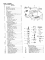
MODEL
113.226880
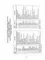
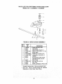
I.IST OF LOOSE PARTS
em
A
B
C
E
F
G
H
J
K
M
N
O
P
Q
P
Q
U
V
W
Q
X
Y
Z
N
Q
S
T
AA
BB
D
R
DD
EE
FF
N
O
Q
AA
AA
BB
BB
CC
Part Name
Qty.
Miter Gauge ...................................................
1
Rip Fence .......................................................
1
Blade Guard and Spreader ............................ 1
Rip Fence Guide Bar, Rear ............................ 1
Leg .................................................................
4
Table Extension ............................................. 2
Side Stiffener ..................................................
2
End Stiffener ..................................................
2
Rip Fence Guide Bar with Rip Scale (Front) .. 1
Bag of Loose Parts.........................................
!
Containing the following:
Leveling Foot ..............................................
4
Hex Jam Nut, 3/8-16 ................................... 8
Hex Nut, 1/4-20 ......................................... 24
Truss Hd. Screw, 1/4-20 x 1/2 .................. 24
Lockwasher, #10 External ......................... 24
Bag of Loose Parts .........................................
1
Containing the following:
Truss Hd. Screw, 1/4-20 x 5/8 .................... 2
Lockwasher, #10 External ........................... 2
Spreader Support ........................................ 1
Switch Key ..................................................
1
Pan Hd. Screw, 10-32 x 5/8 ........................ 2
Lockwasher, 1/4 In. External ....................... 2
Soc. Set Screw, 1/4-20 x 7/8 ...................... 2
Wing Nut, 1/4-20 ......................................... 2
Square Nut, 1/4-20 ...................................... 2
Bag of Loose Parts ......................................... 1
Containing the following:
Jam Nut, 5/16-18 ........................................ 6
Lockwasher, 5/16 External .......................... 6
Spreader Clamp ..........................................
1
Spreader Bracket ........................................
1
Hex Screw, 5/16-18 x 1 ............................... 6
Washer, 21/64 x 5/8 x 1/16 ......................... 6
Bag of Loose Parts ......................................... 1
Containing the following:
Handwheel ..................................................
2
Bracket ........................................................
2
Wrench ........................................................
2
Bevel Pointer ...............................................
1
Wire Tie .......................................................
1
Bag of Loose Parts ......................................... 1
Containing the following:
Hex Jam Nut, 5/816-18 ............................... 6
2
Hex Nut, 1/4-20 ...........................................
Lockwasher, 5/16 External .......................... 8
Hex Hd. Screw, 5/16-18 x 1 ........................ 5
Hex Hd. Screw, 5/16-18 x 1-1/2 .................. 3
Washer, 17/64 x 9/16 x 3/64 ....................... 4
Washer, 21/64 x 5/8 x 1/16 ......................... 8
Fence Guide Bar Spacer ............................ 3
D
F
1
_SB
o
.,<
_-,--
DD
o
0
Q
Q
W
AA
AA
BB
9
Bag of Loose Parts ......................................... 1
Containing the following:
Hex Jam Nut. 5/16-18 ................................. 6
Lockwasher, 1/4 External ............................ 2
Lockwasher, 5/16 Extemat .......................... 8
Pan Head Screw, 8-32 x 3/8 Type "T". ........ 1
Hex Hal. Screw, 5/16-18 x 3/4 ...................... 2
Hex Hd. Screw, 5/16-18 x 1-1/4 ................... 4
Washer, 11/32 x 11/16 x 1/!6 ...................... 8
unpacking and checking
MODEL
113.298090
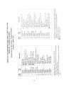
LIST OF LOOSE
item
contents
PARTS
Part Name
Qty.
A
B
C
E
Miter Gauge .....................................................
Rip Fence ........................................................
Blade Guard and Spreader .............................
Rip Fence Guide Bar, Rear .............................
F
H
J
K
L
Rip Fence Guide Bar with Rip Scale (Front) ... 1
Leg ..................................................................
4
Side Stiffener ...................................................
2
End Stiffener ....................................................
2
Table Extension ...............................................
2
Bag of Loose Parts ..........................................
1
Containing the following:
Handwheel ................................................
2
Wrench .....................................................
2
D
G
1
1
1
1
B
L
lO
Bag of Loose Parts ............................................
1
Containing the following:
N
Spreader Support ............................................
1
O
Spreader Clamp ..............................................
1
P
Spreader Bracket ............................................
1
Bag of Loose Parts ............................................
1
Containing the following:
Q
Switch Key ......................................................
1
U
Soc. Hd. Setscrew 1/4-20x7/8 ......................... 2
T
Square Nut, 1/4-20 ..........................
2
X
Lockwasher, #10 External Type ...................... 2
X
Lockwasher, 1/4 External Type ....................... 2
Y
Wing Nut, 1/4-20 ............................................. 2
AA
Pan Hd. Screw, 10-32x5/8 .............................. 2
BB
Truss Head Screw, 1/4-20x5/8 ........................ 2
Bag of Loose Parts ............................................
1
Containing the following:
R
Flat Washer 17/64x9/16x3!64 ......................... 4
R
Flat Washer 21/64x5/8x1/16 ........................... 4
V
Guide Bar Spacer ............................................ 3
W
Hex Nut, 1/4-20 ...............................................
2
W
Hex Jam Nut, 5/16-18 ................................... 10
X
Lockwasher, 1/4 in. External Type .................. 2
X
Lockwasher, 5/16 in. External Type .............. 10
Z
Hex Hd. Screw, 5/16-18xl .............................. 3
Z
Hex Hd. Screw, 5/16-18x1-1/2 ........................ 3
Z
Hex Hd. Screw, 5/16-18x1-1/4 ........................ 4
Bag of Loose Parts ............................................
1
Containing the following:
W
Hex Nut, 1/4-20 .............................................
24
W
Hex Jam Nut, 3/8-16 ....................................... 8
X
Lockwasher, 1/4 Extemal Type .................... 24
BB
Truss Head Screw, 1/4-20xl/2 ..................... 24
CC
Leveling Foot ..................................................
4
Bag of Loose Parts ............................................
2
Containing the following:
R
Flat Washer 17/64x3/4x1/16 ........................... 4
R
Flat Washer 11/32xl 1/16xl/16 ....................... 8
R
Flat Washer 21/64x5/8x1/16 ........................... 8
W
Hex Nut, 1/4-20 .............................................
16
W
Hex Jam Nut, 5/16-18 ..................................... 8
X
Lockwasher, 1/4 Extemal Type .................... 16
X
Lockwasher, 5/16 External Type .................... 8
Z
Hex Head Screw, 5/16-18x1-1/4 ..................... 8
BB
Truss Head Screw, 1/4-20xl ........................ 16
Bag of Loose Parts ............................................
1
Containing the following:
DD
Comer Stiffener Bracket ................................. 4
EE
Comer Support Bracket .................................. 4
Bag of Loose Parts ............................................
1
Containing the following:
W
Hex Jam Nut, 5/16-18 ....... :............................. 2
X
Lockwasher, External 5/16 ............................. 4
Z
Hex Hd. Screw. 5/16-18x3/4 ........................... 2
AA
Pan Cross Screw, Ty "-F', 8-32x3/8 ................ 1
FF
Tie Wire ..........................................................
1
GG
Bracket ............................................................
2
HH
Bevel Pointer ..................................................
1
DD
EE
11
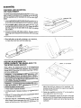
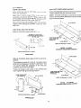
assembly
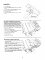
BOTH MODELS
ASSEMBLY OF STEEL LEG SET
Assembly is best done in the location where the saw will
be used.
114-20X1/2 IN.
TRUSS HEAD SCREW
1. From among the loose parts, find the following hardware:
4
*8
*24
*24
*24
3/8-16 HEY, NUT
Leveling Feet
Hex Nuts, 3/8-16
Truss Head Screws, 1/4-20 x 1/2
Hex Nuts, 1/4-20
1/4 Externa| Lockwashers
@
LEVELING
FOOT
114-20 HEX NUT
1/4 IN. EXTERNAL
LOCKWASHER
items marked with an asterisk (*) are shown actual size.
R_v
2. Insert three truss head screws through the three
holes near the top of one Leg. Place the Side Stiffener
up to the Leg, as shown, sothat the three screws line
up with the holes in the Side Stiffeners marked with an
"X" in the illustration.
3. Place a Iockwasher and hex nut on each screw and
finger tighten the hex nut.
4. Following the same procedure as above, continue to
fasten together the remaining Legs and Stiffeners as
illustrated.
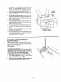
5. Install one 3/8-16 hex nut on each of the Leveling
Feet.
6. Insert a Leveling Foot through the hole inthe bottom
of each Leg so the Leveling Foot pad rests on the
floor.
END
STIFFENER
7. Install another 3/8-16 hex nut on each ofthe Leveling
Feet.
8. Set leg set upright on floor and securely tighten all
nuts.
3/8 IN. HEX NUTS
9. After complete assembly, you may level the saw by
moving the lower nut up or down along the threaded
stud of each Leveling Foot. The upper nut is used to
lock the Leveling Foot into position when the saw is
level.
,
,
IL
LEVELING
i
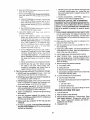
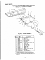
MODEL 113.226880 ONLY
MOUNTING YOUR SAW TO THE LEG SET
(Model 113.298090 will be mounted later)
5116-18 x 1-1/4
HEX HEAD SCREW
1. From among the loose parts, find the following hardware.
*4
*4
*4
*8
FOOT
5/16-18 HEX NUT
Hex Head Screws, 5/16-18 x 1-1/4
Hex Nuts, 5/16-18
Lockwashers, 5/16 In. External
Fiat Washers, 11/32 x 11/16 x 1/16
5/16 IN. EXTERNAL
LOCKWASHER
Items marked with an asterisk (*) are shown actual size.
12
11132 IN. I.D.
FLAT WASHER
2. Placethe sawontop ofthelegsetsothatthe baseof
thesawlinesupapproximately
evenwiththeoutlineof
thetopofthelegset.
3. Frombeneaththesawyouwill be abteto locateand
lineupthe fourmountingholesof the saw basewith
the propermountingholesof the saw basewiththe
propermountingholesinthe leg set assembly.
4. Place one flat washer onto each of the four hex head
screws and insert them into each of the mounting
holes. Be sure the screws go through the saw base
holes and the leg set mounting holes.
5. Install a flat washer, Iockwasher, and a hex nut on
each of the four screws and tighten securely.
HEX HEAD
6. Level the saw to your requirements by adjusting the
leveling feet. Lock leveling feet into position.
FLAT
WAS
HER
SAW BASE
SCREW
""_._|
--""_c_
[
1
7. Securely tighten all leg set screws and nuts.
END
LOCKWAS"E"
17
BOTH MODELS
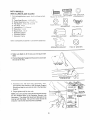
INSTALLING
BEVEL
AND HANDWHEELS
L
POINTER
8-32 x 3/8 SCREW
BEVEL POINTER
1. From among the loose parts, find the following hardware:
1 Bevel Pointer
©
10-32 x 5/8
PHILLIPS SCREW
* 1 Screw, 8-32 x 3/8
2 Handwheels
3/16 IN.
LO CKWASHER
2 Screw, Phillips 10-32 x 5/8
*2 Lockwasher, External 3/16
Items marked with an asterisk (*) are shown actual size.
HANDWHEEL
2. Fasten bevel pointer to cradle assembly with 8-32 x
3/8 screw, as shown. Adjustment of the pointer may
be necessary later.
3. Push handwheels onto shafts, as shown, and fasten
each with a 10-32 x 5/8 phillips screw and Iockwasher.
LOCKWiSHE
TILT
!3
i ER
HANDWHEEL
ELEVATION
HANDWHEEL
assembly
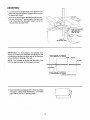
CHECKING AND ADJUSTING
THE TABLE INSERT
The table inset must be llushwith the surface of the saw
table to keep the workpiece from hanging up or binding
with the sawblade as the workpiece is cut by the sawblade.
1. Lower sawblade beneath the table insert and checkto
be surethe screw fastening the insert in Place is snug.
2. Use a straight edge to check near each of the eight
leveling tab positionsto determine if the insert is flush
with the surface of the saw table at all eight
tab positions.
leveling
3. If insert is not flush with table surface, loosen
inser_
fastening screw and pull insert forward to lift from saw
table.
4. Bend with pliers or tap with a hammer, as required,
to make the insert flush with the table top.
r
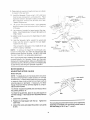
HEELING ADJUSTMENT
OR
PARALLELISM
OF THE SAWBLAOE
THE MITER GAUGE GROOVE
TO
While cutting, the material must move in a straight
line
PARALLELto the SAWBLADE, therefore, both the Miter
Gauge GROOVE and the RIP FENCE must be PARALLEL to the SAWBLADE.
WARNING: if the sawblade is NOT parallel
with
the Miter Gauge Groove, it is said to have "HEEL'.
This condition can cause the workpiece to bind or
move away from the Rip Fence at the end of a rip
cut, possibly causing a kickback.
make sure switch is "OFF" and plug is not conI WARNING: To avoid injury from accide ntai stall,
nected to power source outlet.
side of the tooth you marked on the sawblade. Remember to keep the head of the square flush against
the Miter Gauge Groove.
1. Raise blade to highest elevation.
2. Lift Blade Guard, if already installed, to highest
tion.
3. Mark an "X" on one of the teeth of the sawbiade
posi-
5. Rotate the sawblade so that the "X" on the tooth is
now visible at the rear of the saw.
which
6. Move the combination square to the rear of the saw
and the end of the square blade should just touch the
marked tooth the same as it did at the front of the
sawblade.
is naturally bent to the left.
4. Place the head of a combination square
in the left
Miter Gauge Groove and adjust the ruler blade
of the
square so that the end of the blade just touches
the
14
.
.
9_
If sawblade is not parallel with the Miter Gauge
Groove, you must adjust the position of the sawblade. Use a 3/16 in. hex "L" wrench to loosen the
four adjustment locking screws about 1/2 turn.
3/16 IN.
HEX "L"
WRENCH
Loosen two pan head screws on the rear skirt of the
table about 1/2 turn.
°°\
The mechanism under the table can now be moved
sideways from above by covering the sawblade with
a piece of cardboard and shifting the blade to the
right or left as required.
10. After shifting the sawblade mechanism slightly, recheck the position of the marked tooth of the sawblade at both front and rear.
11. The tooth marked on the sawblade should be parallel to the Miter Gauge Groove after adjustment is
made.
12. Tighten all screws carefully so as not to move
sawblade out of alignment.
113.226880
113.298090
13. Re-check parallelism of marked sawblade tooth to
the Miter Gauge Groove. Repeat the steps for
heeling adjustment if necessary.
BLADE TILT, OR SQUARENESS
BLADE TO TABLE
OF
When the Bevel Pointer is pointing directly to the "0"
mark on the Bevel Scale, the sawblade should make a
SQUARE cut 90° to the table.
90 ° Position
To check for SQUAR ENESS:
turn switch "OFF" and remove plug from power
I WARNING:
avoid injury
from bevel
accidental
source outletTobefore
adjusting
stop. start, I
1. Raise blade all the way UP, raise Blade Guard.
2. TILT blade a few degrees to the LEFT. Now, tilt blade
back to the RIGHT as far as it will go.
3. Place the square against blade. Make sure square is
not touching the TIP of one of the saw TEETH.
15
SHOWN
IS SIMILAR
POINTER
ADJUSTING
SCREW
assembly
r
o
4. If blade is SQUARE to table; check pointer.
/
Q
_/CP_FTgN_N
A. IfPointer DOES NOTpoint to"0" markon the Bevel
Scale, bend pointer to read "0".
"O" POSITION\
_F_
/ k
.,
s il _.l'I/l"111'*_J_',lll'_llI"_\
,o 2# 2s 30 3_ 40 _
10"
Direct Drive
G[
5. If blade is NOT SQUARE to table, the 900 Limit Stop
must be adjusted.
.......... _
_..NGER
I
............
-F
BLADE COVERED
WITH P!ECE OF
CARDBOARD
]CAUTION:
Cover
blade
with p,ece of card- i
board to protect
your
hand.
A. Using a small size screwdriver, reach underneath
saw and loosen BOTH setscrews in 90 ° Stop
Collar.
NOTE: If you can't reach the setscrews turn the
Tilt Handwheel slightly.
/
B. Rotate the Stop Collar moving it away from pivot
nut.
1
/
/
C. Tilt blade RIGHT or LEFT, checking with your
square until blade is square to table.
D. Rotate Stop Collar toward Pivot Nut until it
TOUCH ES the Pivot Nut. Tighten the setscrews.
\,h
E. Check Pointer, if it DOES NOT point to the "0"
mark onthe bevel scale, bend Pointer to read "0".
SETSCREWS
(2)
PIVOT NUT
90° STOP COLLAR
6. Tilt blade to LEFT as far as itwill go. It will stop when
the Pivot Nut is against the 45 ° Stop Collar.
7. Place an ACCURATE square against blade. Make
sure square is nottouching the TIP of one of the saw
teeth.
16
HP
45 °
STOP COLLAR
8. If blade is NOT 45 ° to table, the 45 ° Stop Collar must
be adjusted.
A. Remove Elevation HandwheeL
TILT
SCREW
B. Using a small size screwdriver, reach thru curved
slot in front trim panel and loosen BOTH setscrews
in 45 ° Stop Collar.
NOTE: If you can't reach the setscrews, turn the Tilt
Handwheel slightly.
C. Rotate the Stop Collar moving it IN or OUT and tilt
blade RIGHT or LEFT, checking with your square,
until blade is 45 ° to table.
D. Tighten the setscrews.
NOTE: If you can't reach the setscrews, turn Tilt
Handwheel slightly.
E. Install Elevation Handwheel.
BLADE
BACK
OF SAW
;TOP
_LLAR
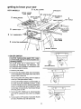
ELEVATION
Whenthe Elevation Handwheel isturned CLOCKWISE,
until it stops, the blade must not be more than 2-5/8
inches above the table. If the blade extends more than
2-5/8 inches, the motor could interfere with the underside of the table causing misalignment.
ELEVATION
/
With the blade extending 2-5/8 inches above the table,
the Stop Collar and Spacer must be against the Elevation Screw Pivot Nut. If the blade extends more than 25/8 inches, loosen two screws in Stop Collar, and
readjust it.
;PACER
/
/
ELEVATION SCREW
PIVOT NUT
TILT SCREW
17
TILT SCREW
PIVOT NUT
SCREW
assembly
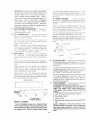
TiLT AND ELEVATION
MECHANISM
The Handwheels should turnfreely without binding. The
turning action can be adjusted bytightening or loosening
the screws in the Bearing Retainer. Both Handwheels
must be removed to reach the adjusting screws.
_ELEVATaON
TILT
HANDWi_EEL
NOTE: When adjusting the screws on the Tilt Bearing
Retainer, hold the nut inside using a 3/8 inch wrench.
The screws for the Elevation Bearing Retainer can be
reached with a small screwdriver through the curved slot
on the front of the saw.
ADJUST THESE
TWO SCREWS
ADJUST
THESE
TWO SCREWS
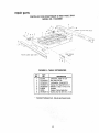
MODEL 113.226880
ONLY
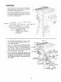
ATTACHING
AND ASSEMBLING
TABLE EXTENSIONS
1. From among the loose parts, find the following hardware: (Quantity indicated is for 2 extensions.)
*8
*8
*8
*8
2
Hex Hal. Screw 5/16-18 x 1
Flat Washer, 21/64 x 5/8 x 1/16
Lockwasher, External 5/16
Hex Jam Nut, 5/16-18
Brackets
5/16-18 x 1
HEX HD. SCREW
11/32 IN. I.D.
FLAT WASH ER
Items rnarked with an asterisk (*) are shown actual size.
5/16 IN. EXTERNAL
LOCKWASHER
5tl 6 IN.
HEX NUT
2. Insert three (3) 5/16-18 x 1 inch long screws through
holes in table.
3. Position Extension against table so screws extend
though holes in Extension.
4. Install flat washer, Iockwashers, and nuts on the
screws. HAND TIGHTEN ONLY.
5. Install other extension in the same way on other side
of table.
\
LOCKWASHER
FLATWASHER
18
BRACKET
6. Line up front and top surface of the Extension with
the front and top of the table at the spots marked
"X" in the drawing. Use a combination square to
line up these edges.
Tighten bolts and nuts
securely.
CHECK WITH SQUARE
AT 2 PLACES
MARKED WITH "X"
7. Put one of the brackets against the right edge of
the right extension so the bracket is lined up with
the FIRST hole near the front of the extension.
Insert a 1 inch long screw through a fiat washer,
through top hole in the bracket, and through the
FIRST hole in the extension. Install a Iockwasher
and nut on the screw. Hand tighten the nut
8. Put one of the brackets against the right rear edge
of the right extension so the bracket is lined up with
the SIXTH hole at the rear of the extension (see
illustration).
9. Insert one of the 1 inch long screws through a flat
washer, through the bracket, and through the
SIXTH hole into the extension. Install a Iockwasher
and nut on the screw. Hand tighten the nut.
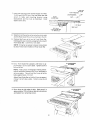
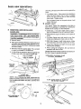
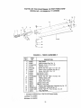
MODEL 113.226880 ONLY
INSTALLING
RIP FENCE GUIDE
AND SWITCH BOX
REAR OF
_-_
EXTENS!ON_-_
Hex Head Screws, 5/16-18 x 1-1/2
Hex Head Screws, 5/16-18 x 1
Hex Head Screws, 5/16-18 x 3/4
Lockwashers, 5/16 External
Hex Jam Nuts, 5/16-18
Flat Washers, 21/64x 5/8 x 1/16
Spacers, 3/4 diameter x 1/2 long
__
"_/__HEX
NUT
7%.ih
"'1-
_'_'.N
_
_
WASHER
"_.
,OOKWAS.E"
.gX#? D
/
EXTERNAL
BRACKET
LOCKWASHER
/
HEX
5/16_18
x
1 IN.
HEAD
SC REW
5/16-18 x 1 IN.
G
BARS
1 From among the loose parts, find the following hardware:
*3
*3
*2
* 10
*6
"8
*3
"--._-_
5/16-18 x 3/4
HEX HD. SCREW
5/16 IN. EXTERNAL
LOCKWASHERS
5/16-18 x 1-1/2 IN. HEX HD. SCREW
Items marked with an asterisk (*) are shown actual size.
5/16 IN.
HEX JAM NUT
5/16-18 x 1 IN.
HEX HD. SCREW
--!21/64 IN. WASHER
1/2 IN. SPACER
19
assembly
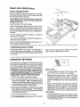
2_ insed a 5/16-18 x 1-I/2 inch long hex head screw,
external !ockwasher and fiat washer through the
SECOND slot _nthe front fence bar
3. Piace t/2 inch _ong Spacer over screw threads and
thread hex head screw into first hole On the right side
o_the cast iron table skirt until finger tigh_ Guide Bar
should be in a vertical position.
/
/
4
SPACER
Mount Switch to Guide Bar with (2.) two 5/16-18 x
314 hex head screws, Iockwashers, and nuts. Securely tighten both bolts.
5_ Insert 1-1/2 inch long screw tl_rough external
tockwasher, flat washer and through the first slot in
the Guide Bar. Place 1/2 inch long Spacer over
screw threads.
Swing Guide 8at to horizontal
position and thread the hex head screw into the
hole of the table skirt Finger tighten.
FLAT
1-1i2" HEX
HD. SCREW
LO4b"_WASHER
LOCKWASHER
HUT
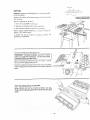
6. Insert 1-!/2 inch long screw through flat washer and
the FOURTH slot in the Guide Bar. Place 1/2 inch
long spacer over screw threads, Insert screw into
slot in bracket and attach a lockwasher and nut.
l
Finger tighten.
5/164 8 X 3/4"
flEX HD.
BRACKET
!
/
LOCKWASHER
/
1-1i2" HEX
HD. SCREW
2O
SPACER
FLAT
WASHER
1_' HE;< HD.
SCREW
7, _nsert one inch _ong screw and flat washer in F_RST
THIRD and EIGHTH sbt of the rear Guide Bar and
attach lo table and mounting bracket using
_ockwashers and hex nuts as illustrated_ Hand
tighten at this time,
FLAT WASHER
LOCKWASHER
_"_ _
",,
REAR
9'
NUT ............. ;_
GUiD E BAR
==========================================================_:_:`_;_`._::::_::_t:_`_L_Z_-`_`_
-....
L_z_
i
/
_
I
3RD'
SLOT
SLOT
8TH SLOT
tFOR
TO
8_
MOUNTING
BRACKET)
t
Slide the Front Guide Bar as far as it wilt go to the right
and the Rear Guide Bar as far as i1will go to the lefL
\\\
9. Position Rip Fence at left end of Front Guide Bar,
holding up the rear end while engaging front end with
Front Guide Bar. Lower fence onto tab!e_
NOTE: It may be necessary to loosen Fence Knob
to allow Fence to be installed on Rear Guide Bar.
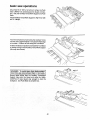
10. Move Front Guide Bar upwards until fence is ap*
proximately 1/32 inch above tabae. Tighten screw at
left end of Bar.
8 THICKNESSES
OF PAPER
NOTE:
Fotd a piece of newspaper making 8 thicknesses and place between Rip Fence and table to
act as a spacer. This will tloid the Fence off of tl_e
table approximately
1/32 inch.
Adjust Rear Guide Bar so that the Fence is approximately 1/32 inch above table, Tighten screw at end
of Bar.
11. Move fence to right edge of table. Make sure it is
approximately 1/32 inch above table at front and rear
and tighten four remaining screws.
8 THICKNESSES
OF PAPER
\
assembly
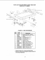
MODEL 113.298090 ONLY
ATTACHING AND ASSEMBLING
TABLE EXTENSIONS
1. From among the loose parts, find the following hardware: (Quantity indicated is for 2 extensions.)
*8
*8
*8
*8
"16
"16
"16
*4
4
4
2
Hex Hd. Screws, 5/16-18 x 1-1/4
Flat Washers, 21/64 x 5/8 x 1/16
Lockwashers, External 5/16
Hex Jam Nut. 5/16-18
Truss Head Screws, 1/4-20 x 1
Hex Nut, 1/4-20
Lockwashers, External 1/4
Flat Washers, 17/64 x 3/4 x 1/16
Corner Support Brackets
Corner Stiffener Brackets
Brackets
HEX HD. SCREW
5/16-18 X 1-1/4
EXTERNAL
LOCKWASHER
5/16 IN.
FLAT WAS H ER
21/64 IN. I.D.
HEX NUT
5/16-18
TRUSS HD. SCREW
1/4-20 X 1 IN.
FLAT WASHER
17/64 IN. I.D.
HEX NUT
EXTERNAL
1/4-20
LOCKWASHER
1/4 IN.
CORNER
STIFFENER
BRACKET
CORNER
SUPPORT
BRACKET
BRACKET
Items marked with an asterisk (*) are shown actual size.
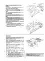
2. Position saw upside down on floor.
CORNER
STIFFENER
NOTE: To protect the finished surfaces of the saw
and extensions, lay a piece of heavy paper or cardboard on the floor.
3 Install Corner Support Brackets, Corner Stiffener
Brackets, 1/4-20 x 1 inch truss head screws, 17/64
inch flat washers, 1/4 inch external lockwashers, and
1/4-20 hex nuts as shown. Hand tighten only.
17164 DIA.
BRACKET
FLAT
WASHER
1/4-20
_-H=.nRT
BR'A'CKi_Tf
TRUSSHEAO
_.1/4
_..-_"_._}"_,,_'-_
'\\\
tJ_J_
IN. EXTERNAL
__LOCKWASHER
\ \_ __.]._
SCREW
,-_-_
_ _
THIS
EDGE
TOWARD
4. Insert four (4) 5116-18 x 1-1/4 inch hex head screws
into holes on inside edge of one extension.
5. Install 11/32 i.D. flat washer, 5/16externam Iockwasher,
and 5/16-18 hex nut on the end of each screw. Just
start nut on end of screw.
6. Slide the extension with hardware into four slots in
side of table. LINE UP FRONT EDGE OF EXTENSION WITH FRONT EDGE OF TABLE and tighten all
screws and nuts.
7. Repeat for other extension.
WASHER
LOCKWASHER
22
5/16-18
X 1-1/4
SCREW
TABLE
8. Inserta1/4-20x I trussheadscrewthroughbottom
holein the bracket, and through the FIRST hole in
the right hand extension. Install a iockwasher and
nut on the screw. Hand tighten the nut.
9.
Insert a 1/4-20 x I truss head screw through bottom
hole in the other bracket and the FOURTH hole of
the extension. Install a Iockwasher and nut on the
screw. Hand tighten the nut.
10. insert the 1/4-20 x 1 truss head screws through the
FIRST and FOURTH holes in the left extension
without brackets. Install a Iockwasher and nut on
each screw and hand tighten.
MODEL 113,298090
INSTALLING
RIP FENCE
AND SWITCH BOX
1. From among the loose parts, find the following hardware:
*3
*3
*2
*8
*4
*3
"10
G
GUIDE BARS
Hex Head Screws, 5/16-18 x 1-1/2
Hex Head Screws, 5/16-18 x 1
Hex Head Screws, 5/16-18 x 3/4
Hex Jam Nuts, 5/16-18
Fiat Washers, 21/64 x 5/8 x 1/16
Spacers, 3/4 dia. x 1/2 long
Lockwashers, 5/16 External
5/16-18 x 3/4
HEX HD. SCREW
5/16-18
5/16 IN. EXTERNAL
5/16 iN.
LOCKWASHERS
HEXJAM NUT
5/16-18 x 1 IN.
HEX HD. SCREW
X 1-1/2 IN. HEX HD. SCREW
Items marked with an asterisk (*) are shown actual size.
21/64 IN. WASHER
1/2 IN. SPACER
REAR
GUIDE
BAR
2. Position guide bars on floor and install hardware as
_
/
shown. Just start the nuts on the end of the screws,
I \,_
EXT. LOCKWASHER
8TH SLOT
5/16 IN
REX HEAD
DO NOT screw nuts on all the way.
(FOR MOUNTING-"__,-\
I "
TO BRACKET)
SWITCtH
`='''''-_
_
ASSEM.__%'_t
MOUNTING-H-OLES
(FOR
TO
MOUNTING
BRACKET)
_
_6
_-_._
_..__.._
2N D SLOT _"_'__
,x
H
IFLAT
3RD
_
__-
SCREW
1 IN. LONG
SLOT /
[
..,<.._(_.)'_J_
FLAT
S P AC E R
_
_
WASHER/
_ _.,_J"
R
1ST SLOT
5116 IN.
CK
1ST SLOT
FRONT
23
WASHER
]
GUIDE
BAR
ER
assembly
5/16-18
3. Mount Switch to Guide Bar with two 5/16-18 x 3/4 hex
head screws, Iockwashers, and nuts. Securely tighten
both nuts.
_/"
"l
HEX
j
EXTERNAL
_"\_
5/16-18
EXTERNAL
X 3/4
HEX
NUTS
LOCKWASHERS
LOCKWASHERS
HD. SCREWS
4. Place Front Guide Bar against saw table and drop it
in place engaging the screws in the slots. Make sure
the spacers are between the rail and the table.
5. End of Front Guide Bar must be 7-5/16 in. from side
of saw table. This is important so that Rip Fence
Indicator can be aligned.
5/16-18
x 1.1/2
HEX HD.
6. With the blade of your combination square set to 1/4
inch, gauge and adjust guide rail so the edge of the
rail is 1/4 inch ABOVE the edge of the table. Securely
tighten nuts.
/
7. Install 5/16-18 x 1-1/2 hex head screw through the
FOURTH slot in Front Guide Bar (that lines up with
bracket), through the 1/2 inch spacer and the Bracket.
Install a 5/16 in. external iockwasher and 5/16-18 hex
7-5/16
/
IN,
1
jam nut.
8.
Remove the three screws from rear of right table
extension.
9.
Attach the Rear Guide Bar in a similar manner to the
Front Guide Bar. Make sure that the end of the bar
is 1! inches from the side of the saw table.
10. Reinstallthree truss head screws, Iockwashers and
istight.hex
nuts removed in step 8. Check that all hardware
_-_'<_)_l__\_
J
11. insert 5/16-18 x 1 hex head screw through the
EIGHTH slot and bracket.
Install 5/16 external
iockwasherand5116
. SCRE
hex jam nut. Tighten securely.
HEX HD. TRUSS HD.
SCREWS
24
SCREWS
MODEL
113.2980g0
MOUNTING
ONLY
YOUR SAW TO THE LEG SET
5/16-18 x 1-1/4
HEX HEAD SCREW
1. From among the loose parts, find the following hardware.
*4
*4
*4
*8
5/16-18 HEX NUT
G
Hex Head Screws, 5/16-18 x 1-t/4
Hex Nuts, 5/16-18
Lockwashers, 5/16 In. External
Fiat Washers, !1/32x 11/16x 1/16
5/16 iN. EXTERNAL
LOCKWASHER
items marked with an asterisk (*) are shown actual size.
11/32 IN. i.D.
FLAT WASHER
2. Place the saw on top of the Leg Set so that the base
of the saw lines up approximately even with the
outline of the top of the Leg Set.
3. From beneath the saw you wiU be able to locate and
line up the four mounting holes of the saw base wffh
the proper mounting holes in the Leg Set assembly.
4. Place one flat washer onto each of the four hex head
screws and insert them into each of the mounting
holes. Be sure the screws go through the saw base
holes and the Leg set mounting holes.
5. Install a fiat washer, Iockwasher, and a hex nut on
each of the four screws and tighten securely.
SAW BASE
6. Level the saw to your requirements by adjusting the
Leveling Feet. Lock Leveling Feet into position.
!
FLAT WASHER
7. Securely tighten all Leg Set screws and nuts.
}|
LOCKWASHER/[-["_
//
HEXNUT""'/_'-'r-a'J
H
MODEL 113.298090 ONLY
ALIGNING TABLE EXTENSIONS
1. "Tap" extensions upwards or downwards, using a
block of wood and a hammer until they are even with
the top of the saw table. Be sure end of extensions are
even with front edge of saw.
BLOCK
OF
\
_OOD
I
t
t
NOTE: If necessary slightly loosen the screws and
nuts that connect the extensions to the table.
f
3. Tighten screws.
25
assemb|y
4. Lay a straight piece of wood or a framing square on
table to act as a straightedge.
If outer edge of
extension is higher of lower than the table surface:
A. Slightly loosen nuts holding bracket to extension
using 7/16 in. wrench.
B. Move end of extension up or down until outer edge
is even with table surface. Check with Guide Bar.
Tighten nuts.
C. Re-check INNER edge of extension to make sure
it has not moved. Readjust, if necessary.
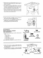
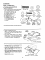
BOTH MODELS
1. From among loose parts, find:
1 Wire Tie
2. Snap wire tie into 1/4 inch hole in right side of
cabinet.
Route motor cord from inside cabinet
through the wire tie. Secure cord in wire tie. Keep
any extra cord on outside of cabinet. Do not push
extra cord inside cabinet.
EXTENSION
REMOVED
PICTURE
CLARITY
V
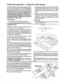
BOTH MODELS
MOUNTING YOUR SAW TO A
WORKBENCH
WIRE
TiE
1/2
To mount the saw on workbench, make sure that there
isan o_ning inthe top of the bench the same size as the
opening in the bottom of the saw so that the sawdust can
drop through. Recommended working height is33 to 37
inches form the top of the saw table to the floor.
NOTE: All dimensions in inches.
4 HOLES
7/16 DIA.
FRONT OF SAW
26
FOR
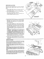
BOTH MODELS
The Fence should slide easily a!ong the Guide Bars and
always remain in alignment (parallel to sawbiade and
Miter Gauge Grooves).
The alignment is maintained by a spring underneath the
Fence which bears against the Front Guide Bar.
To move the Fence, loosen the Lock Handle and grasp
the Fence with one hand at the front.
For very close adjustments, grasp the Guide Bar with
both hands and move the Fence with your thumbs.
-b
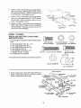
BOTH MODELS
SELF-ALIGNING
SPRING
ADJUSTMENT
Place Fence on saw but DO NOT LOCK IT.
Move the REAR END of the Fence slightly to the right of
left. When you release it, the Fence should "spring" back
to its original position.
If it does not, the spring pressure must be INCREASED.
assemb|y
Loosen the screws.
2. Move spring slightly towara front ot Fence. Tighten
screws,
# the Fence does not slide easily a_ong _he Bars the
press_re of the spring can be REDUCED
1 Loosen tr_escrews
2. Move spring sJight_ytoward rear of Fence
Tig,q_en
SCreWS.
/
RiP FENCE
ALBGNMENT
/
SLIDE SPRING
TO
ADJUST
PRESSURE
ADJUSTMENT
WARNING: A misaltglned Rip Fence can cause
kickbacks and jams. To avoid injury, !ol!ow these
instructions until the fence is prepedy aligned.
HEX SCREWS
The Rip Fence must be PARALLEL with the sawbtade
and Miter Gauge Grooves. Move Fence untiJ it is a_on_
s_deot Groove, DO NOT LOCK iT I! should be paralle_
to Groove. _fi_ is not:
FENCE
HEAD
1 Loosen the Hex },-leadscrews,
2 Hold Fence head tightly against Bar, Move end ot
Fence so that =tis parallel with Groove,
3, Alternately tighten the screws
\
\
4 Re-check alignment.
5. Repeat steps, as needed
\
ADJUSTING
RiP SCALE
iNDiCATOR
1, Turn Elevation Handwheei clockwise untit blade is up
as high as it will go.
BMPORTANT: BLADE musl be SQUARE 190'_) to
[ABLE, in order to ALIGN Rip Fence,
LOCK
2, Using a rule, position Fence on right side of sawblade
2 inches from the side of the teeth, tighten Lock
Handle.
3, Loosen screw holding the Indicator, adjust so that it
points to "2" on the Rip Scale, tighten screw.
NOTE: It you cannot adjust indicator so that it points
to "2." loosen the screws holding the Front Guide Bar
and move the Guide Bar.
28
HANDLE
/
BOTH
5 ,__u
-j?
MODELS
INSTALBNG
BLADE
1/4+20 x 7/8
SOCKET HD,
., ,
1/4.20 × 5/8
SETSCREW 1/4 iN. EXTERNA..
TRUSS HD SuRb:W
LO_KWAStTER
GUARD
!. From among the loose parts,, Iind the fo_owing hard _
ware:
"2
*2
*4
'2
*4
*2
*2
1
1
1
Truss Head Screws+ I/4.-20 x 5/8
Socket Head Setscrew, I/4-+20 x 7/8
Flat Washer, 17/64 × 9/16 x 3/64
Hex Nuts+ 1/4-20
Lockwashers+ 1/4 E×temal
Wing Nuts, 1/4-20
Square Nuts, t/4o20
Spreader Support
Spreader Bracket
Spreader C_amp
t/420
HEX NUT
t/4-20
SQUARE NUT
SPREADER SUPPORT
1/4 20 WING NUT
SPREADER C.AMP
Items markedwith an asterisk (") are shown actuat size,
SPREADER BRACKET
17/64 !.D WASHER
2. Make sure blade is all the way up and square with
table.
3. Position Spreader Support on Rod until it is even with
the end of the Rod
\
WITH
4, Assemble the 7/8 inch _ong setscrews, nuts
lockwashers and washers to the Spreader Support
Bracket and slip the nuts into the s_otin the Spreader
Support.
5. Finger tighten only the hex nuts.
NOTE: Be sure to put the socket head setscrew through
the slot shaped holes in the Spreader Bracket (see
illustration). This al!ows the Guard and Spreader to be
fined up with the blade. Be sure the socket end of the
setscrew is at the hex nut end of the assembly.
29
TABLE
assembly
6 Lay a piece of flat straight wood and a square on saw
lable and rotate the Spreader Suppod untitthe Bracket
is align_ with square.
7_ Make sure end of Support, Bracket and Rod are even.
Using a 1!8 inch hex "L" wrench, tighten the setscrews
only, Check that the Spreader Support cannot be
rotated on the Spreader Rod.
!NDS OF SUPPORT
AND BRACKET
TO
BE EVEN WiTH
END OF ROD
TIGHTEN
SETSCREW
ONLY
!1
IMPORTANT:
To work properly, the spreader must
always be parallel to the sawblade and adjusted so the
cut workpiece will pass on either side of the Spreader
without binding or skewing to the side
SPACE EQUAL
3 THICKNESSES
TO APPROX.
OF PAPER
KERF
NOTE: The Spreader is thinner than the width of the
KERF by approximately six thicknesses of paper.
[
WOOD
l"....... _'?----
...............
tBLADE'_
I /I.............
"_
.................
' ................
?
s?E,DE.i,
1
I SPACE
EQUAL
• 3 THICKNESSES
!
APPROX,
OF PAPER
LOOKING
8. Make two folds in a small piece (6 x 6 in.) of ordinary
newspaper making three thicknesses. The tolded
paper will be used as a "spacing gauge".
I
!
3O
TO
DOWN
ON
SAW
9. Raise b!ade to maximum height and r%ke sure b_ade
is square to the saw tabb
I O. hstatl the Spreader C!a_x© using 1/4..£0 x 5/8 truss
head screws, bckwashers,
and wing nuts. P_ace
f
Spreader between Spreader Clamp and Bracket.
Move Spreader
forward _,_ntil atl th_ee are in line,
T_ghten Wing screws,
1!.
Lift up boh Anti-Kickback
Paw_s. i%e_t setscrew
wrench or a pencil into r.,otches to ho_d the Paw_s out
of the way.
12. Lay a piece of straight fiat wood against the saw..
b_ade Insert lo[ded paper between Sp,_eader and
strip of wood.
13. MAKE SURE TH E HE X NUTS UNDERNEATH
LOOSE!
ARE
14_ Hold the Spreader
t_ghtly against the wood and
make sure the wood is against the saw blade.
Tighten the hex nuts,
This wiII atign the Spreader in the middle of the cut
(KERR) £_ade by sawbIade.
NOTE:
To remove the Guard for non-through
cuts,
loosen the Wing Nuts a_3d slide the Guard back and
upward off the Spreader Bracket.
DO NOT DISTURB
THE SET-raNG OF THE SPREADER
BRACKET.
When replacing the Guard, siide the Spreader down and
forward between the Spreader Clamp and Spreader
Bracket unfit it rests as shown. Make sure Wing Nuts are
tightened securely, this ietsyou remove and replace the
Guard without disturbir_
the Spreader alignment.
BOTH
MODELS
ADJUSTING
MITER
GAUGE
MITER GAUGE
NOTE: Thegraduations are manulacturedto veryctose
toIerances which provide suitabte accuracy for average
woodworking. In some cases where extreme accuracy
is required, make a trial cut ana then re-check it with an
accurate square or protractor, tf necessary, the Miter
Gauge head can then be swiveled slightly to compensate and then tocked.
The HEAD should be SQUARE (90 °] with the barwhen
the pointer points to "0".
To check for squareness, place an accurate square on
the Miter Gauge. If the head is NOT SQUARE with the
bar:
1. Loosen the Lock Knob.
2. Position the head square with the bar. Tighten the
Lock Knob.
The swiveling movement of the head can be adjusted by
t_ghtening or loosening the set screw bcated inside of
the head using a 1/8 in. hex "L" wrench.
3. Loosen the screw and adjust the pointer, so it points
to zero.
31
getting to know your saw
BOTH MODELS
6
BLADE GUARD
MITER GAUGE
LOCK KNOB
5
8
SPREADER
SAW BLA
ANTIKICKBACK
PAWLS
MITER
HEAD
MITER GAUGE
TABLE
9
3
4
FENCE
INSERT
HOLES FOR
ATTACHING
FACING
EXACT-I-CUT
TILT HANDWHEE|
FENCE
LOCK KNOB
2
ELEVATION HANDWHEEL
/
/
1
ON-OFF
SWITCH
C
©
ON-OFF SWITCH
sure the blade guard is correctly installed and
CAUTION:
Before turning switch "ON", make i
operating properly.
©
____
@
The On,Off Switch has a locking feature. THIS
FEATURE IS INTENDED
TO PREVENT UNAUTHORIZED AND POSSIBLE HAZARDOUS USE
BY CHILDREN AND OTHERS.
(YELLOW
KEY
PLASTIC)
A. Insert key into switch.
B_To turn saw ON, stand to either side of the blade,
never in line with it, insert finger under switch lever
and pull END of lever out.
After turning switch ON, always allow the blade to
come up to full speed before cutting.
Do not cycle the Motor Switch on and off rapidly, as
this may cause the sawblade to loosen, in the
eventthis should ever occur, allowthe sawblade to
come to a complete stop and re-tighten the arbor
nut r_rmatly, not excessively. Never leave the saw
while the power is "ON".
_.----__
I'
C. To turn saw OFF, PUSH leverin. Never leavethe
saw until the cutting tool has come to a complete
stop.
D. To dock switch in OFF position, hold switch IN with
one hand, REMOVE key with other hand.
k,,,
32
2
3
WARNING:
For your own safety, lower blade
or other cL4t}ng tool be!ow table surfacer
(H
btade is tilted_ return il to vertical
90% position}., Always fork the switch "OFF".
When
saw is not m use, _emove key and keep it in a
safe place_
Also_ #,, the event of a power
t
/ faiture (a:t of Vour lilhls
go out} turn swttch
off, lock it by _emoving
the key,
This wit
touches the top surface of th.e Eixtensios
n this
case, the facing mus_ be shorter titan the Fence.
This wi_ prevent thin mater;al from sliding under the
Rip Fence
t prevent
Slots are provided
the saw from
starling
!..
t2e.
up again
5
MITER
GAUGE
, . . head is !ocked in
t:×)sitior_ tot crosscutting or mitering by t_ghte r_ing the
Lock K_,::,b ALWAYS LOCK _T SECURELY WHEN
tN USE.
when
in tI_e Miter Gauge for at£aching
to make it easier to Odt iong
pieces. Be _x.'.,sitive Faci_.g does net irs_edere wth
the proper operation of the Sawb!ade Gua:d.
............................................................
an Auxi!iary Facir_g
ELEVATION
HANDWHEEt
....
lowers the b!ade,
tum
c_ockwise
coun_,erclockwise
to k._wer.
T_LT HANDWHEEL..._i_ts
elevates or
to elevate,
Setect a suitab!e piece of snK)oti_ straigh_ wood
two ho_es through it and attach it wi!h screws.
the blade for beve!
cutting.
Turn c_ockwise to ti_t toward
c_ockwise to flit toward ri_._:}ht.
ieft, cocmte_.
dri_I
NOTE: When bevel crosscutting,
attach Facing so
that it extends to the right of the Miter Gauge and use
the Miter Gauge in the groove to the right of She
b_ade.
Wher_ the blade is thted to the kt}FT as far as il wi_i
go. it shouid be a_ 45" ,_o me tab@ and the bevel
indic££o_ should poir_t to 45"'.
...................LOCK
KNOB
NOTE:
There are LIMIT STOPS inside the saw
wI_ ci_ prevent the Made from tilting beyond 45 '_to the
LE,_T ar_d 90" to _he RIGHT. ( See "ADJUSTMENTS
AND ALiGNMBNTS"
5ecfioa 'BLADE
TIL[,
OR
',SQUAR!:.Nif:: SS OF BI..AD{:: TO TABLE').
4
R!P FE}{CE
... is locked ,'.,_p}ace by tightening
the Lock Knob.
To move the Fe;_ce, loosen the
Knob and grasp the Fence wi{h one hand at the
front.
,,
_,5 =:_SLOT
6
} _oies a_e provided in _he Rip Fence {o,_ attaching a
wood facing when using the Dado Head, or Molding
Head.
Select a piece
mate!y 3/4 inch
Fence, and at
permit clamping
of smooth straight wood approxi-.
thick, at least as long as the Rip
least 7-1/2 inches wide {high) to
of Featherboards.
Attach it to the Fence with three Round Head #10
Wood Screws 2 inches _oP,
g. To remove the facing,
loosen the screws, s!ide _he facing forward and putt
the screws through the round he;ca.
WOOD
_- AUXILLARY
FACING
......
BLADEGUARD..,
must a_waysbe in p!ace and
working properly for all thmosawm9 cuts. Tha_ is, ati
cuts whereby the blade cuts oompiete_y through the
workpiece.
q-o rein/dye the Guard for speciaI operations, loosen
the Wing Nuts and slide the Guard back and upward
off the Spreader Bracket. DO NOT DISTURB THE
SETTING OF THE SPREADER BRACKET.
Wher_ replacing the Guard, slide the Spreader down
and forward between the Spreader
C_amp and
S_reaaer Bracket until the bottom and rear edges oi
al{ three are even
Make sure both Wing Nuts are
hand t_ghtened securely.
FACING
7
TABLE
INSERT.
or installing
WARNING:
start, turn
_ _is removabie 1or remewng
b_ades or other cumng Ioo_s
To avoid injury due to accldentaI,
switch
"OFF"
and remove
plug
from power source outlet
before removing
InserL
A Lower the blade below the table su_ace
}
I
]
B. Raise Blade Guard.
"_%
/
ROUND
t0
MODEL
WOOD
///
HEAD
C. Loosen screw.
/
SCREWS
D, Lift insert from front end, and pull toward tront of
saw.
113.298090
NEVER OPERATE THE SAW W_THOUT THE
PROPER INSERT IN PLACE. Use the saw blade
insert when using a saw blade. Use the combination
DadoiMolding insert when using a Dado or Mol@ng
head.
!f you are making a rip type cut in material thinner
than 31!6 inch while _he Fence is positioned over the
depressed area of Table Extension, the facing shoutd
be attached to the Fence so that the bottom edge
33
basic saw operations
The HOLLOW side of the collar must be against the
blade.
E. To replace insert. Place insed into opening in
table and push toward rear of saw to engage
Spring Clip and until key slot in insert will drop
over screw. Tighten screw.
/
Do not tighten screw to the point where it will
deflect the insert.
9 EXACT-n-CUT
8
REMOVING
SAWBLADE
The "yellow" Plastic Disc imbedded in the table in
front of the sawblade, is provided for marking the
location of the "sawcut" on the workpiece.
AND iNSTALLiNG
A. Check Disc. If it is above table surface, place a
piece of hardwood on top of it and tap it down.
WARNING: TO avoid injury due to accidental
start, push switch "OFF" and remove plug
from power source outlet before removing or
installing sawblade.
A. Remove Insert.
B. With blade 90 ° (square to table) cut off a piece of
wood,
C. Puff Miter Gauge back until wood is over Disc.
Using very sharp pencil, mark a line on Disc.
D. W_th Miter Gauge in right hand groove, follow
same procedure and mark another _ine on Disc.
B. Place open end Arbor Wrench on flat surfaces of
saw arbor and closed end Arbor Wrench on nut.
Position wrenches as shown, holding your hands
weft above blade.
E. These lines indicate the "path" of the cut (kerf)
made by the sawblade.
F. When cutting the workpiece, line up mark on
workpiece with line on Disc.
C. With Arbor Wrench against table, PULL wrench
on arbor nut forward to LOOSEN nut.
Use the Hold-Down Clamp (optional accessory) on
the Miter Gauge for greater accuracy.
D. To TIGHTEN nut, hold Arbor Wrench against rear
of table, push arbor nut wrench toward rear.
\
\
PULL
TO LOOSEN
/I _ "
SHOWN WITH HOLD-DOWN
CLAMP
(OPTIONAL
ACCESSORY)
_/
/
\
!/
.¢>.d
..............
/>.?.
CLOSED END
ARBOR NUT WRENCH
........
NOTE: When installing the blade, make sure the
teeth are pointing toward the front of the saw and
that the blade and collars are clean, and free from
any burrs.
HEX
_;jv
BLADE GUARD SHOWN IN "PHANTOM"
FOR PICTURE CLARITY
NUT
I
34
BOTH MODELS
WORK
AUX_L|ARY
HELPERS
Before cutting any wood on your saw,
"Basic Saw Operations/
FENCE!WORK SUPPORT
Make one using a piece of 3/8 inch and 3/4 inch plywood
Fasten together with glue and wood screws.
study aH of the
NOTE: Since the Push Block is used with the Auxiliar
Fence, the 4-3/4 inches dimensions must be held iden
tical on both the pieces.
Notice tt_at in order to make some of the cuts, it is
necessary to use certain devices, '_Vork Helpers", tike
the Push Stick, the Push Btock and the Auxiliary Fence/
Work Support, which you can make Yourself.
After you have made a few practice Cuts, make up these
"helpers" before starting any projects.
Make the "Push
Stick" first.
3/4
PLYWOOD
27
PUSH STICK AND PUSH BLOCK
Make the Push Stick using a piece of 1 x 2.
SLIGHTLY
LESS
THAN
THICKNESS
OF WORKPIECE
UP TO
3/8"
THiS
FACE
AND THiS
EDGE
MUST
BE
pARALLEL
30
3/8 PLYWOOD
NOTE:
15
NOTE:
45 °
All dimensions
NOTCH
All dimension
In inches
MODEL 113.298060
AUXILIARY FENCE/WORK SUPPORT
in inches
PUSH STICK
3/4
Make the Push Block using a piece of 3/8 in. and 3/4 in.
plywood.
PLYWOOD
2O
The small piece of wood 3/8 x 3/8 x 2-1/2 inches should
be GLUED to the plywood. DO NOT USE NAILS. This
is to prevent dulling the sawbtade
in the event you
mistakenly cut into the Push Block.
Position the handle in the center of the plywood and
fasten together with glue and wood screw.
THESE
EDGES MUST
BE PARALLEL
/
/
3/4
THIS
FACE
AND THIS
EDGE
MUST
BE
PARALLEL
PLYWOOD
\
NOTE:
3/8 PLYWOOD
_
All dimension
in Inches_
_4-3/4-_
\
MODEL
113.226880
AUXIUARY FENCE/WORK SUPPORT
318
NOTE:
All dimensions
in inches
I
3/8 PLYWOOD
PUSH BLOCK
35
5"1/
safety instructions for basic saw eperations
BOTH MODELS
BEFORE
EACH USE:
1. Inspect yoursaw
2. Keep work area clean
A. CSuttered areas and benches invite accidents.
Floor must not be slippery from wax or sawdust.
A To avoid injury from accidental starting,unplugthe
saw. turn the switch off and remove the Switch Key
before raising or removing the Guard, changing
the cutting tool, changing the setup or adjusting
anything_
B. To avoid burns or other fire damage, never use the
saw near flammable liquids, vapors or gases
3. Plan your work - plan ahead to protect your eyes,
hands, face, ears.
B Check for a_ignment of moving parts, binding of
moving parts, breakage of parts, saw stability,and
any other conditions that may affect the way the
saw works, if any part is missing, bent, or broken
m any way, or any electrical part does not work
properly, turn the saw off and unplug the saw.
C Replace damaged, missing, or failed parts before
using the saw again.
WARNING: To avoid injury, don't do layout,
assernbny, or setup work on the table while
the blade is spinning, it could cut or throw
anything hitting the blade.
A. USE THE RIGHT TOOL - Don't force tool or
attachment to do a job it was not designed for.
B. Dress for safety:
D. Use the Sawbiade Guard, Spreader, and AntiKickback Pawls forany thru-sawing (wheneverthe
blade comes through the top of the workpiece).
Make sure the Pawlswork properly. Make sure the
Spreader is in line with the sawblade.
1. Do not wear loose clothing, gloves, neckties or
jewelry (rings, wristwatches).
They can get
caught and draw you into moving parts.
2. Wear non-slip footwear.
E REMOVE ADJUSTING KEYS AN D WRENCHES.
Form habit of checking for and removing keys and
adjusting wrenches from tool before turning it on.
F To avoid injury from jams, slips or thrown pieces
(kickback and throwback):
1. USEONLY RECOMMENDED ACCESSORIES
(See page 47). Follow the instructions that
come with the accessories. Using other accessories may be dangerous.
3. Tie back long hair.
4. Roll long sleeves above the elbow.
5. Noise levels vary widely. To avoid possible
hearing damage, wear ear plugs or muffs when
using saw for long periods of time.
6. Any power saw can throw foreign objects into
the eyes. This can cause permanent eye damage. Wear safety goggles (not glasses) that
comply with ANSI Z87.1 (shown on package).
Everyday eyeglasses have only impact resistant lenses. They are not safety glasses. Safety
goggles are available at Sears retail catalog
stores. Glasses or goggles not in compliance
with ANSI Z87.1 could seriously hurt you when
they break.
2 Choose the right blade or cutting accessory for
the material and the type of cutting you plan to
do
3. Never use grinding wheels, abrasive cut-off
wheels, friction wheels (metal slitting blades)
wire wheels or buffing wheels. They can fty
apart explosively.
WEAR
4. Choo se and inspect your cutting tool carefully.
a To avoid cutting tool failure and thrown shrapnel (broken pieces of blade), use only 10" or
smaller blades or other cutting tools marked
for speeds of 3450 rpm or higher,
b. Always use unbroken, balanced blades designed to fit this saw's 5/8 inch arbor.
YOUR
7. For dusty operations, wear a dust mask along
with the safety goggles.
C. Inspect your workpiece. Make sure there are no
nails or foreignobjects in the part of the workpiece
to be cut.
c_ When thru_sawing (making cuts where the
blade comes through the workpiece top),
always use a 10 inch diameter blade. This
keeps the Spreader in closest to the blade.
d. Do not over tighten arbor nut. Use arbor
wrenches to "snug" it securely.
e. Use only sharp blades with property set teeth.
Consult a I_rofessional blade sharpenerwhen
in doubt.
D. Plan your cut to avoid KICKBACKS and THROW.
BACKS - when a part or all of the workpiece binds
on the blade and is thrown violently back toward
the front of the saw.
1. Inspect yourworkpiece. Make sure there are no
nails or foreign objects in the part of the workpiece to be cut.
f. Keep blades clean of gum and resin,
5. Adjust table inserts flush with the table top.
NEVER use the saw without the proper insert.
6 Make sure all clamps and locks are tight and no
parts have any excessive play.
36
2. Never cut FREEHAND: Always use either a
Rip Fence, Miter Gauge or fixture to position
and guide the work, so it won't twist, bind on the
blade and kickback.
I. NEVER turn the saw"ON" before clearing the tabl
of all tools, wood scraps, etc., except the wor_
piece and related feed or support devices for th
cut planned.
J. AVOID ACCIDENTAL STARTING - Make sur
switch is "OFF" before plugging saw in.
3. Make sure there's no debris between the workpiece and its supports.
4. When cutting Irregu_arty shaped workpieces,
p_an your work so it will not slip and pinch the
Made:
a_ A piece of molding, for exampte, must lie fiat
or be held by a fixture or jig that will not ie_:it
twist, rock or slip while being cut. Use jigs or
fixtures where needed to prevent wo_kpiece
shifting.
WHENEVER
5. Use extra caution with large, very srna_ or
awkward workpieces:
1. Before actuaJly cutting with the saw, watch it while
runs for a short while. If it makes an unfamiliar nois
or vibrates a _ot,stop immediately. Turn the saw ot
Unplug the saw. Do not restart until finding and fixir
the problem.
2. Make sure the top of the arbor or cutting too_ turf
toward the front of the saw.
a_ Use extra supports (tables, saw horses,
blocks, etc.) forany workpieces {arge enough
to tip when not he_d down to the table top.
NEVER use another person as a substitute
for a TaMe Extension, or as additional support for a workpiece that is longer or wider
than the basic saw tame, or to help feed,
support, or pull the workpiece.
b. Never confine the piece being cut off. That is,
the piece NOT against the Fence, Miter Gauge
or fixture. Never hold it, clamp it, toucil it, or
use length stops against it. it must be free to
move. if confined, it could get wedged against
the blade and cause a kickback or throwback.
3. Set the cutting tooJ as low as possible for the c_
you're planning.
4. KEEP CHILDREN AWAY. All visitors should be kel
a safe distance from work. Make sure bystanders a_
clear of the saw and workpiece.
5o Let the blade reach full speed before cutting.
6. DON'T FORCE TOOL. it will do the job better ar
safer at itsdesigned rate. Feed the workpiece into t_
blade only fast enough to let it cut without boggir
down or binding.
7. Before freeing any jammed material:
A. Turn switch "OFF".
c. Never cut more than one workpiece at a time.
d. NEVER turn the saw "ON" before cleadng
the table or all tools, wood scraps, etc.,
except the workpiece and related feed or
support devices for the cut planned.
B. Unplug the saw.
C. Wait for all moving parts to stop.
D. Check blade, Spreader and Fence for proper alig
ment before starting, again.
4. Plan the way you will push the workpJece through
A NEVER pulJ the workpiece through. Start and
finish the cut from the front of the table saw.
8. To avoid throwback of cut off pieces;
A. Use the Guard Assembly.
B. NEVER put your fingers or hands in the path of
the sawblade or other cutting too!.
B. To remove loose pieces beneath or trapped insk
the Guard:
C. NEVER reach in back of the cutting tool with either
hand to hold-down or support tile workpiece, remove wood scraps, or for any other reason.
D.Avoid awkward operations and hand positions
where a sudden slip could cause tinge rs or hand to
move into a sawblade o r other cutting tool.
!. Turn saw "OFF".
2. Remove Switch Key.
3. Wait for blade to stop before lifting the Guan
BEFORE
Always keep good footing
LEAVING
TIlE SAW
1. Turn the saw off.
2. Wait for blade to stop spinning.
3. Make workshop child-proof. Lock the shop. Disco
nect master switches. Remove the yelbw Swit4
Key. Store it away from children and others
qualified to use the tool.
F. Push the workpiece against the rotation of the
blade. NEVER feed material into the cutting tool
from the rear of the saw.
G.Always push the workpiece
sawblade.
IS SPiNNiNG
WARNING: DoWt let familiarity (gained from frequent use of your table saw) cause a careless
mistake. ABways remember that a careless fract_on of a second is enough to cause a severe
_njury.
b. Use a different, better suited type of too_for
work that can't be made stable.
E. DON'T OVERREACH.
and balance.
SAW BLADE
all the way past the
4. Unplug the saw.
H. As much as possible, keep your face and body to
one side of the sawblade, out of line with a possible
kickback or throwback.
37
basic saw operation -using
the miter gauge
can help prevent workpiece twisting and throwbacks.
Attach it to the holes provided. Make the facing long
enough and big enough to support your work. Make
sure, however, it will not interfere with the sawblade
guard.
The MITER GAUGE IS USED when CROSSCUTTING,
MITER CUTTING, BEVEL CUTTING, COMPOUN D MITER CUTTING, DADOING and when RABBETING
AND MOLDING across the end of a narrow workpiece.
J
the following safety precautions in addition to the
WARNING: For your own safety, always observe I
safety instructions on pages 2, 3, 4, 5, 36, & 37.
ADDiTiONAL SAFETY INSTRUCTIONS
CROSS CUT TYPE CUTS.
FOR
Before starting:
3. Use jigs or fixtures to help hold any piece too small to
extend across the full length of the Miter Gauge face
during the cut. This lets you properly hold the Miter
Gauge and workpiece and helps keep your hands
away from the blade.
While cutting:
1. Never use the Rip Fence when crosscutting.
1. To avoid blade contact, always hold the Miter Gauge
as shown in this section.
2. An auxiliary wood facing attached to the Miter Gauge
CROSSCUTTING
WORKPI
ECE
1
Crosscut is known as a cutting or shaping operation
made across the width of a workpiece.
The graduations on the Miter Gauge provide accuracy
for average woodworking. In some cases where extreme accuracy is required, when making angle cuts, for
example, make a trial cut and then re-check it with an
accurate square, or protractor.
I [
itI
l
TABLE
If necessary, the Miter Gauge head can be swiveled
slightly to compensate for any inaccuracy.
NOTE: The space between the MiterGauge Bar andthe
groove inthe table is held to a minimum during manufacturing.
For maximum accuracy when using the Miter Gauge,
always "favor" one side of the groove in the table. In
other words, don't move the Miter Gauge from side to
side while cutting, but keep one side of the bar riding
against one side of the groove.
NOTE: Glue a piece of sandpapertothe face ofthe Miter
Gauge head. This will help prevent the workpiece from
"creeping" while it is being cut.
When using the Miter Gauge in the LEFT hand groove,
hold the workpiece firmly against the Miter Gauge head
with your left hand, and grip the lock handle with your
right.
The Hold-Down Clamp (optional accessory) should be
used on the Miter Gauge for greater accuracy.
The Miter Gauge may be used in either of the grooves in
the table. Make sure it is locked.
When using the RIGHT hand groove, hold the workpiece
with your right hand and the Lock Handle with your left
hand.
WARNING: To avoid blade contact or kickback,
hold Miter Gauge properly.
When cutting long workpieces, invert Auxiliary Fence/
Work Support and position it on top of the Guide Bars to
support the workpiece as near to the end as possible. If
thisdoes not adequately support the workpiece, you can
make a simple support by clamping a piece of plywood
to a sawhorse. See illustration above.
AUXILIARY
FENCE/
...........
Use the Hold-Down Clamp (optional accessory) on the
Miter Gauge for greater accuracy.
38
LEFT HAND
REMOVED
FOR
REPET_TIVE
CUTTING
REPETITIVE cuTrtNG is known as cutting a quantity of
pieces the same length without having to mark each
piece.
1. Use the Stop Rods (optior_al accessory) on{y for
cutting duplicate pieces 6 inches tong and _onger.
2. When making repetitive cuts from a _ong workpiece,
make sure it is adequately supported.
Use the Hold-Down Clamp (optional accessory)
the Miter Gauge for greater accuracy.
on
--
AUXILIARY
FENCE/
WORK SUPPORT
3. NEVER USE THE RIP FENCE AS A LENGTH STOP
BECAUSE
THE CUT-OFF
PIECE COULD
BIND
BETWEEN THE FENCE AND "["HE BLADE CAUSING A KICKBACK.
4. When making repetitive cuts shorter than 6 inches,
clamp a block of wood 2 inches tong to the table to act
as a length stop. Do not clamp directly to the bottom
edge of the table because the "swivel" of the clamp
will not grip properly. Place a small block of wood
between the bottom edge of the table and the "C"
clamp.
CAUTION: Avoid kickback from twisting the
workpiece.
When clamping the block, make
sure that the end ot the b_ock is wel_ _n front of
the sawblade. Be sure it is clamped securely.
5. Slide the workpiece along the Miter Gauge until gt
touches the block, hold it securely. Use Hold-Down
Clamp _optional accessory} for greater accuracy.
6. Make the cut, pull the workpiece back. turn saw off,
wait for blade to stop and remove cut off piece before
continuing.
MITER CUTTING
MITER CUTTING is known as cutting wood at an angle
other than 90 ° with the edge of the wood. Follow the
same procedure as you would for crosscutting.
TABLE
Adjust the Miter Gauge to the desired angle, and lock it.
The Miter Gauge may be used in either of the grooves in
the table.
TOP V_EW
When using the Miter Gauge in the LEFT hand groove,
hold the workpiece firmly against the Miter Gauge head
with your left hand, and grip the Lock Knob with your
_h_n using the RIGHT hand groove, hold the workpiece
with your right hand and the Knob with your left hand.
Use the Hold-Down Clamp (optional accessory) on the
Miter Gauge for greater accuracy.
39
basic saw operations
BEVEL
W0R
K.,°f
ECE
C ROSSCUTTING
BEVEL CROSSCUTTING is the same as crosscutting
except that the wood is also cut at an angle, 0ther than
90 o with the flat side of the wood.
TA6LE
Lower blade to about 2 inches above the table top
before tilting blade. Failure to do this may result in
damage to your saw.
\
\
\
\
Adjust the blade to the desired angle.
Use the Miter Gauge in the groove to the RIGHT of the
blade. It cannot be used in the groove to the LEFT
because the Blade Guard will intedere. Hold the workpiece with your right hand and the Lock Handle with your
left hand.
Use the Auxiliary Fence/Work
support of the workpiece.
Support
for additional
Lay it across the Guide Bars to support the workpiece as
near to the end as possible.
Use the Hold-Down Clamp (optional
Miter Gauge for greater accuracy.
COMPOUND
accessory) on the
MITER CUTTING
COMPOUND MITER CUTTING is a combination of
miter cutting and bevel crosscutting. The cut is made at
an angle other than 90 ° to both the edge and the flat side
of the wood.
Adjust the Miter Gauge and the blade to the desired
angle. Make sure Miter Gauge is locked.
using the rip fence
;_----
RIPPING, BEVEL RIPPING, PLOUGHING. MOLDING,
RESAWlNG AND RABBETING are performed usingthe
RIP FENCE together with the AUXILIARY
FENCE/
WORK SUPPORT, PUSH STICK OR PUSH BLOCK.
---
24'
5 q6"
APART
KERFS ABOUT
Ii
Before starting:
the following safety precautions in addition to the
I
ARNING: For your own safety, always observe I
safety instructions on pages 2, 3, 4, 5, 36, & 37.
1. To avoid kickbacks and slips into the blade, make
sure the Rip Fence is parallel to the sawblade.
ADDITIONAL
2. Check the Anti-Kickback Pawls. (See BASIC SAW
OPERATION- USING THE RIP FENCE.) The Pawls
must stop a kickback once it has started. Replace or
sharpen Anti-Kickback Pawls when points become
dull.
SAFETY
INSTRUCTIONS
1. NEVER use the Miter Gauge when ripping.
2. Use a Push Stick whenever the fence is 2 or more
inches from the blade. When thru-sawing, use an
auxiliary fence and push block whe never the fence
must be between 1/2 and 2 inches of theblade. Never
thru-saw rip cuts less than 1/2 inch wide.
3. Plastic and composition (like hardboard) materials
may be cut on your saw. However, since these are
usually quite hard and slippery, the Anti-Kickback
Pawls may not stop a kickback. Therefore, be especially careful in your set-up and cutting procedures,
3. When using a Push Stick or Push Block, the trailing
end of the board must be square.
A Push Stick or
Block against an uneven end could slip off or push the
work away from the fence.
While cutting:
1. To avoid kickbacks and slips into the blade, always
push forward on the section of the workpiece between
the sawblade and the Rip Fence. Never push forward
on the piece being cut off.
4. Never rip anything shorter than 10" long.
5. A FEATHERBOARD
can help guide the workpiece.
40
WORKPIECE
RIPPING
Ripping is known as a cutting operation aIong the tengt H
of the workpiece.
TABLE
]_T
Position the Fence to the desired WIDTH OF RIP and
lock in place.
ALWAYS
SUPPORT
LON
OR WiDE WORKP|ECE_
Belore starting to rip, be sure:
1. Rip Fence is paraflel to sawblade.
2. Spreader is properly a_igned with sawblade.
3. Anti-Kickback Pawls are functior_mg properly.
When ripping LONG BOARDS
always use a work support.
or LARGE PANELS,
A simple one can be made by clamping a piece
plywood to a sawhorse,
of
Keep your hands out of the blade path_
WARNING:
To avoid kickback, use LEFT hand
ONLY to guide the workpiece.
Do not FEED tl_e
workpiece with your left hand.
1
Stop your left thumb at the front edge of the table. Finish
the cut with the appropriate pusher.
Feed the workpiece by pushing forward only on the part
of the workpiece that will pass between the btade and I he
fence.
/
Once the trailing
end is on the table:
When "WIDTH OF RIP" is 2 inches or wider, use the
Push Stick to finish pushing the work all the way past the
blade.
41
basic saw operations
When WIDTH OF RIP is 1/2 inch to 2 inches, the Push
Stick CANNOT be used because the Guard will interfere. USE the Auxiliary Fence/Work Support and Push
Block.
Attach Auxiliary Fence/Work Support to Rip Fence with
two "C" clamps.
Feed the workpiece by hand along the Auxiliary Fence
until the end is approximately 1 inch past the front edge
of the table. Continue to feed using the Push Block.
Hold the workpiece in position and install the Push Block
by sliding it on top of the Auxiliary Fence/Work Support
(this may raise Guard).
WARNING:
To avoid injury from
BAFFLE
blade contact, I
never thru-saw cuts narrower than 1/2 inch wide. '1
Narrow strips thicker than the Auxiliary Fence/Work
Support may enter the Guard and strike the Baffle.
CAREFULLY raise Guard only enough to clear the
workpiece. Use Push Block to complete cut.
42
USING FEATHERBOARDS
SAWmNG
FOR THRU
Featherboards are NOT employed for thru-sawing
erations when using the Miter Gauge.
op-
Featherboards are used to keep the work in contact with
the Fence and table as shown, and to help stop kickbacks.
Add 7-1/2 inch Mgh flat facing board tothe Fence, the full
length of the Fence.
Mount Featherboards to Fence and table as shown, so
that leading edges of Featherboards wil! support workpiece.
WARNING: Make sure the Featherboard against
the edge presses only on the uncut position (in
front of the blade). Btmight othenNise pinch the
blade i the kerr and cause a kickback.
Before starting the operation (switch "OFF" and cutter
below tabte surface):
1. install Featherboards so they exert pressure on the
workpiece; be positive they are secure, and
2. Make sure by trial that the Featherboards will stop a
kickback if one should occur.
RESAWaNG
RESAWING is a thru-sawing cut made by ripping a piece
of wood through its thickness Do not attempt to resaw
BOWED or WARPED material.
NOTE: To RESAW a piece of wood wider than 3-3/8
inches, it will be necessary to remove the blade guard
and usethe Auxiliary Fence/Work Support. (See"WORK
HELPERS").
Clamp it to the table so that the workpiece will SLIDE
EASILY but not TILT or MOVE SIDEWAYS without
BINDING between the two Fences.
Do not clamp directly to the bottom edge ot the table
because the "swivel" of the clamp will not grip properly.
Place a small block of wood between the bottom edge of
the table and the "C" clamp.
WARNING:
For your own safety
1.
DO not "Back up" (reverse feeding) while
resawing becausethis could cause a kickback,
2.
Make first pass to a depth slightly more than
WARNING: Install Blade Guard immediately
completion of the resawing operation.
43
upon
basic saw operations
"C"
CLAMPS
:EATHERBOARD
USING FEATHERBOARDS
THRU SAWING
CLAMPS
FOR NON-
FEATHERBOARD
WORK
SUPPORT
Featherboards are NOT employed during non thrusawing operations when using the Miter Gauge.
USE FEATHERBOARDS FOR ALL OTHER NON THRUSAWING OPERATIONS (when Sawblade Guard must
be removed). Featherboards are used to keep the work
in contact with the Fence and table as shown, and to stop
kickbacks.
Add 7-1/2 inch high flat facing board to the Fence, the full
length of the Fence.
BLADE
Mount Featherboards to Fence and table as shown, so
that leading edges of Featherboards will support workpiece until cut is complete, and the workpiece has been
pushed completely past the cutter (sawblade, Dado
Head, Molding Head, etc.) with a Push Stick, as in
ripping.
PATH
t/
BLADE PATH
Before starting the operation (switch "OFF" and cutter
below table surface):
1. Install Featherboards so they exert pressure on the
workpiece; be positive they are secure, and
2. Make sure by trial that the Featherboards will stop a
kickback if one should occur.
Sawblade Guard as soon as the non thru-sawing
I WARNING:
For your own safety, replace the
operation is complete.
RABBETING
RABBETING is known as cutting out a section of the
corner of a piece of material, across an end or along an
edge.
FIRST CUT
RABBET.
To make a RABBET requires cuts which do not go all the
way through the material. Therefore, the Blade Guard
must be removed.
1. Remove Blade Guard.
I SECOND
I
CUTfJ
J
RABBETING
ALONG
THE EDGE
2. For rabbeting along an edge (long way of workpiece) as shown, add facing to Rip Fence approximately as high as the workpiece is wide. Adjust Rip
Fe nce and blade to required dimensions; then make
first cut with board flat on table as any rip (type) cut;
make second cut with workpiece on edge. Follow all
precautions, safety instructions, and operational instructions as for ripping, or riptype operations, including Featherboards and Push Stick, etc.
RABBETING
ACROSS THE END
3. For rabbeting across an end, for workpiece 10-1/2
inches and narrower, make the rabbet cut with the
board flat on the table. Using the Miter Gauge fitted
with a Facing, follow the same procedures and instructions for cross cutting making successive cuts
across the width of the workpiece to obtain the desired width of cut. DO NOT use the Rip Fence for
WARNING: For your own safety, install blade
guard immediately upon completion of rabbeting
operation.
Some rabbet cuts can also be made in one pass of the
workpiece over the cutter using the Dado Head or
Molding Head.
rabbeting across the end.
44
PLOUGHMNG
AND
MOLDING
PLOUGHING is grooving with the grain the long way o_
the workpiece, using the Fence. USE proper ho_ddowns and feed devices.
MOLDING is shaping the workpiece with the grain the
_ongway of 1he wo.rkpieca,
using the Fence. Use pro, per
hold--downs and _eed devices.
PLOUGHING
MOLDING
CUTTING
PANELS
When cutting panels (whenever fence is positioned
outside of table surface), ALWAYS use the Auxiliary
Fence/Work Support.
1. Unlock Fence and raise rear end.
2. Position Auxiliary FenceNVork Support as shown and
attach it with two "C" clamps.
\
©
DADOnNG
Instructions for operating the Dado Head are contained
in booklet furnished with the Dado Head.
®
®
The arbor on the saw, is only long enough so that the
widest cut that can be made is 13/16 inch wide.
It is not necessary to install the outside loose collar
before screwing on the arbor nut. Make sure the arbor
nut is tight.
JJ
ALWAYS USE DADO INSERT LISTED UNDER "RECOMMENDED ACCESSORIES."
LOOSE
7r""_,
i
I
I
il
IRE'
OVE
NI!"sAwA"°
SAWBLADE
_L.._.._NSTALL
___J
MOLDING
------..__/_'
ARBOR NUT Jr
When using the Dado Head it will be necessary to
remove the Blade Guard and Spreader. USE CAUTION.
USE MITER GAUGE, FENCE, FEATHERBOARDS AND PUSH STICKS AS REQUIRED.
WARNING: For your own safety, always replace
I the blade, Guard and Spreader when you are
I finished Dadoing.
COLLAR
DADO
BACK
AND
HEAD
OF SAW
CUTTING
Instructions for operating the Molding Head are contained in a booklet furnished with the Molding Head.
TION.
USE MITER
BOARDS AND PUSH
Always use Molding Insert listed under "RECOMMENDED ACCESSORIES".
GAUGE, FENCE, FEA-FHEF
STICKS, ETC. AS REQUIREr:
the blade, Guard
and Spreader when you
are
WARNING: For your own safety, always rep.lace
finished Molding.
When using the Molding Head, it will be necessarY to
remove the Blade Guard and Spreader. USE CAU-
45
motor
LUBRiCATiON
AND MAINTENANCE
conditions likely to permit accumulations of dust, dirt,
or waste within the motor, a visual inspection should
be made at frequent intervals. Accumulations of dry
dust can usually be blown out successfully.
1. The beadrK:js,in both end shields of the motor, have
been lubricated at the factory with correct lubricant.
No other part of the motor requires lubrication.
2. if disassembly of the motor is necessary, itshould be
returned to your nearest Sears retail or main-order
store in order to prevent voiding the guarantee.
NOTE: Motors used on wood-working tools are
particularly susceptible to the accumulation of sawdust and wood chips and should be blown out or
"vacuumed" frequently to prevent interference with
normal motor ventilation.
NOTE: The speed of this motor cannot be regulated
or changed.
3. Every effort should be made to prevent foreign materiat trom entering the rr_tor. When operated under
maintenance
WARNING: To avoid injury from accidental start,
turn switch "OFF" and remove plug from power
source outlet before maintaining or lubricating
your saw.
Do not allow sawdust to accumulate inside the saw.
Frequently blow out any dust that may accumulate
inside the saw cabinet and the motor.
Frequently clean your cutting tools with Craftsman Gum
and Pitch Remover.
A coat of automobile-type wax applied to the table will
help to keep the surface clean and allow workpieces to
slide more freely.
It the power cord is worn or cut, or damaged in any way,
have it replaced immediately.
Make sure the teeth of the Anti-Kickback Pawls are
always sharp. To sharpen:
1. Remove Blade Guard.
2. Rotate Pawl toward rear of Spreader so that teeth are
above top of Spreader.
3. Hold Spreader with left hand and place Pawl over
corner of workbench.
4. Using a small round file (smooth cut) sharpen the
teeth.
46
lubrication
2. F}Aevation scr,_}w threads and pivot r;ut_ (First c;e_r_ w,_th
Crsflsmar_ Gum and Pitct_ Remover)
i'he saw motor b_._v' ,qgs __ave bee>, packed at the facto_y
with [_ope, _ i_b!ica_sl u:,d >:)qu_'e no add}tioi_a! t_Jbrica _
t]ou_ The follow _!] par_s shotAd be oi!ed occasioe, a!iy with
SAE no, 20 oi __o 30 e_;g _e ot
1 Yi!t screw threads a>.d pivot nut(First
man Gum ,__r-_d
Pitch Remover.)
STOP
clean witt_ Crafts-
3, Cradle bearing
points.
4. Bearing points
Rip Fe_ce.
in Guard
Assembly,
Miler
Gauge
{;cmd
COLLAR
ELEVATION
PWOT
SCREW
NUT
VATION
SCREW
/
STOP
COLLAR
®
TiLT SCREW
PIVOT
NUT
sears recommends
the following
Caster Sets .....................................
"7 In Molding
*7 In. Molding
ITEM
CAT. NO.
ITEM
9-22222
Head Set ...............................
head .....................................
CAT, NO.
See Cata_op
7 in. Dia, Dado Head ...................
Sanding Whee_ .......................................
See CataIo_
Miter Gauge Stop Rods ...................................
9-29924
Miter Gauge HoEd-Down Clamp .........................
9-29928
Taper Jig ....................................................
See CataJo.q.
Universal Jig ...............................................
See Catalog
"Power 3ooi Know How Handbook"
............
9-291 t7
or 9-22221
See Catalog
See Catalog
Moiding.iDado
Insert for 7 In, Dia. Molding
or Dado Head .......................................................
9-29933
Work Light
...............................................
See Catalog
Sawdust Cotection
System ...............................
9-29962
7 _n. Dia Adjustable Dado Head ................. See Catafog
*
Smaler
diameter
Molding Heads cannot be
because they do to provide adequate depth of cut,
accessories
The above recommended
accessories
are curren_
were available at the time this manuat was printed
used
47
and
troubleshooting
t WARNING:
youroutlet
own safety,
switch
"OFF" and always remove pnug II
from power For
source
before turn
trouble
shooting.
TROUBLE
SHOOTING
- GENERAL
REMEDY
PROBABLE CAUSE
TROUBLE
Excessive vibration.
1. Blade out of balance.
Cannot make square
cut when crosscutting.
1. Miter gauge not adjusted
properly.
Cut binds, burns or
stalls motor when
ripping.
.
1. See "Adjustments" section "Miter Gauge."
1. Sharpen or replace blade.
.1. Dull blade or improper
tooth set.
2. Blade is Heeling.
3. Warped board.
2. See "Adjustments" section, "Heeling Adjustment .."
3. Make sure concave or hollow side is facing
"down," feed slowly.
4. See "Assembly" section, "Aligning Rip Fence."
4. Rip fence not parallel to
blade.
Cut not true at 90 ° or
45° positions.
Tilt and elevating
handwheel turn hard.
TROUBLESHOOTING
Discard Blade and use a different blade.
5. Spreader out of alignment.
1. Stop screw not properly
adjusted.
5. See "Assembly" section, "Installing Blade Guard."
1. Sawdust on threads of tilt
1. See "Maintenance" and "Lubrication"
1. See "Adjustments" section, "Blade Tilt, or
Squareness of Blade to Table."
screw or elevating screw.
2. Bearing retainers too
l tight.
section.
2. See "Maintenance" section, "Tilt and Elevation
Mechanism"
- MOTOR
NOTE: Motors used on wood working tools are particularly susceptible to the
accumulation of sawdust and wood chips and should be blown out or 'Vacuumed"
frequently to prevent interference with normal motor ventilation.
TROUBLE
PROBABLE CAUSE
REMEDY
Excessive noise.
1. Motor
1. Have motor checked by qualified service technician. Repair service is available at your nearest
Sears store.
rMotor fails to develop
lull power. NOTE:
Low Voltage:
(Power output of
motor decreases
1. Circuit overloaded with
lights, appliances and other
motors.
2. Undersize wires or circuit
too long.
1. Do not use other appliances or motors on same
circuit when using the saw.
rapidly with decrease
in voltage at motor
3.
terminals. For example,
a reduction of 10% in
voltage causes a
reduction of 19% in
maximum power
output of which the
f
motor is capable, and
a reduction of 20% in
General overloading of
ix)we r company facilities.
(in some sections of the
country, demand for electrical power may exceed
the capacity of existing
generating and distribution
systems.)
voltage causes a
reduction of 36% in
incorrect fuses or circuit
breakers in power line.
.
2. Increase wire sizes, or reduce length of wiring.
See "Motor Specifications and Electrical Require
meres" section.
3, Request a voltage check from the power company.
4. Install correct fuses or circuit breakers.
maximum power
output.)
48
TROUBLESHOOTING
TROUBLE
I
OI ° fauna tO come
oto_ stads .....
to tuI_ speed
- MOTOR
PROBABLE
up
Motor overheats,
(CONT'D)
REMEDY
CAUSE
t. Low voltage will not
trip relay.
2. Windings burned out
or open.
3, Starting re!ay not
operating,
1 Request
I_ Motor overloaded
1.
or replaced.
3. Have relay replaced
Feed work s_ower into btade,
2. Ctean out sawdust to provide
norma_ aft circulation
through motor, See "Maintenance
"L.ubricalion _'section.
through motor due to
sawdust0 accumulating
inside of saw.)
Motor stalls
(resulting in blown
fuses or tripped
circuit breakers,
check from the power company.
2 Have motor repaired
2_ Improper cooting, (Air
circulation restricted
Relay will not operate.
voltage
1, Have relay replaced and request
from the power company.
1_ Burned contacts (due to
extended hold4n periods
caused by _ow line voltage,
etc.)
2, Saw not in upright position.
3. Loose or broken connectors
'° and
a vo!_age check
2, P!ace saw in upright position.
3. Have wiring checked and repaired
1_Have relay replaced
2, Request voltage check from the power company,
1. Started relay not operating
2. Voltage too low to permit
motor to reach operating
speed.
3 Fuses or circuit breakers
do not have sufficient
3. lnstalt proper size fuses or circuit
breakers
capacity,
Frequent opening of
fuses or circuit
breakers.
1. Feed work slower into blade,
2. Install proper size fuses or circuit breakers,
!. Motor overloaded
2. Fuses or circuit breakers
do not have sufficient
capacity,
3, Relay not operating
(motor does not reach
speed.)
3. Have relay replaced.
49
repair parts
II)
//
I.l.
\
03
LU
>,
n
nE_
LUeO
m_
OCO
_-'GO
f,O
0
Zo4
\
\
"o
Iz:Z
(3,..I
I-03
m
..I
I/]
I.IT"
11,
50
/
x
oJ
_)
><
x
o
x
.£
c_.
_
Im
if)
--_v E
E_0_
o,_ _
o.__-
_
_
_
E=
-,
<-5-o
(/)
rf3
W
o8
_j
03 _
£r
_
tj)
oo
-_
,_
oo_=0__o
_
•
Oo
Z
o
O
Z
coo
0
0
i_
_i..0
o
LO
0
r_
oo
._
_o
.QI-
€=)
8
E
w_
O
z_
LL.d
(am _,
+
{X:
{3
_., o
s_
_
m
_o
_o
_
_o o9
ooo0,_
°_ m
z- (at)
m
I.I-
zN
EQ.
N_
Z
_
!
Ill
-d
i
I
<o
E
_z
O
6
m
€
.£
,m
o
m
!-
Z=
O.
O
Z
Q.
m
w
vz
51
repair parts
I
<_
I
U_
ILl
:>
g:
il/
Q
l'-c_
Ij_co
a:: o'*
iI
I
a_
I
.r=T_0
Z_
c>oo
v,=co
03_i.. _-<_
rr"
nCN
03
.J
rr"
<€
rt
I
!1
,4
52
E .£
('d
....... OJ
<,:_ ¢,
£B
×
0
0
:v
:V
I
O
6
w
=_oSg
_a
8o
,zTa
N
E
C)
0
£Z.,
w
c4
--
-"
:I: 0
Z_
_"
0
..J
'
I"
Z
_j
C'j
"a:_
¢}
o7
TM
kU
..........................
r! .....................................................................................................................................................................................................................................................................
if)
0
C'd
6
'_'
_'_
X
C
o_
E
.__2
@
Z
X
@
0
_-×x
_
N
I
m
ca
h
z:z:_
m
,gD_
.
-
o o_
_5
==
oo
o0cc _ z m:_ o,o
mm_:
. .
_m_
4m4m
_0
0_
•
,:<
mz
S_.==
m
z;
;
N
g
+_
_m_
6
=
¢''N
N
_e_
N
N_
o
I
Od
_
]
L
•
53
£
._
-,_ _ ,_
_
_
mm
p-.
,_=: * ,.. _,.:
@
_
+
@
;>
©
repair parts
PARTS
LiST FOR CRAFTSMAN
MODEL NO. 113.226880
10 UNCH TABLE SAW
& 113.298090
4
5
15
7
\
7
/
13
FIGURE
KEY
NO.
3 - GUARD
PART
NO.
1
62415
2
62516
3
62650
4
STD541425
5
62517
6
STD512515
7
62522
8"
62810
9
62410
10
62519
11 i 62520
12
62974
13
STD551025
14
60208
15
STD581025
*
8
ASSEMBLY
1
DESCRIPTION
Guard, Saw
Pin
Bumper, Snap In
* Nut, Lock 1/4-20
Link, Guard
* Screw, Pan Hd., 1/4-20 x 1-1/2
Spacer, Link
Blade, Spreader
Pin, 1/4 x 1-3/64
Spring, Pawl
Spacer, Pawl
Pawl
* Washer, 17164 x 1/2 x 1/32
Nut, Push
Ring, Retaining 1/4
Standard Hardware lem - May be purchased locally
If this part is removed, discard and replace with a new
push nut.
54
PARTS LiST FOR CRAFTSMAN
MODEL NO. 113.226880
10 tNCH TABLE SAW
& 113.298090
I0
4
5
6
2
I
13_R
fl4
t &--16
FIGURE
KEY
NO.
1
2
3
4
5
6
7
8
9
10
11
12
13
14
15
16
17
PART
NO.
4 - FENCE ASSEMBLY
DESCRiPTiON
62693
Plug, Button
Knob (Includes Key No. 1)
62692
STD551031
* Washer, 21/64 x 1/2 x 1/32
Indicator, Fence
62775
9404336
* Screw, Pan Hd. Type "T" 4-40 x 1/4
62941
Head, Fence (Includes Key No. 4)
423567
Screw, Sems 3/8-16 x t/2
A Channel, Fence
62526
[] Channel, Fence
62582
STD600805
* Screw, Pan Hd. Type 'q-" 8-32 x 1/2
62528
Spring, Fence Lock
Lock, Rear Fence
62529
Roller, Rear Fence
62531
A Rod, Fence Lock
62530
[] Rod, Fence Lock
62944
508112
Spring, Head Alignment
(Includes Key No. 17)
* Lockwasher, External No. 10
ST D551210
STD611005 ! * Screw, Type "A", Hex Hd. No. 10 x 1/2
Pad, Alignment
62532
* Standard Hardware Item - May be purchased
A Model 113.228880
[] Model 113.298090
55
locally.
11
repair parts
PARTS LIST FOR CRAFTSMAN 10 INCH TABLE SAW
MODEL NO. 113.226880
5
\
FRONT
REAR
GUIDE
BAR
(REF)
FIGURE 5- TABLE
KEY
NO.
PART
NO.
i
2
3
4
5
6
7
8
817745
STD541231
STD551231
STD523110
STD551031
818308
62539
STD523115
L
EXTENSIONS
DESCRIPTION
*
*
*
*
Extension, Table 10 x 20
Nut, Hex 5/16-18
Lockwasher, External 5/16
Screw, Hex Head 5/16-18 x 1
Washer, 11/32 x 11/16x 1/16
Bracket
Spacer, Fence Guide Bar
* Screw, Hex Hd. 5/16-18 x 1-1/2
* Standard Hardware Item - May be purchased locally
56
GUIDE
BAR
(REF)
PARTS
LmST FOR CRAFTSMAN
10 iNCH TABLE SAW
MODEL NO. 113.298090
FRONT
15
REAR
GUIDE
BAR
(REF)
/
12
/
, o
/
<../
\ ,, ,
\ll
%
11
FIGURE
KEY
NO.
1
2
3
4
5
6
7
8
9
10
11
12
13
14
15
4
6 - TABLE
PART
NO.
EXTENSIONS
DESCRIPTION
9-29957
1" Extension Assembly, Complete
60323
Screw, Serrated Truss Hd., 1/4-20 x 1
818308
Bracket
STD551231 '* Lockwasher, External 5/16
STD541031 * Nut, Hex 5/16-18
STD551225 * Lockwasher, External 1/4
STD541025 * Nut, Hex 1/4-20
62590
Extension, 10 x 27
62539
Spacer, Fence Guide Bar
STD551031 * Washer, 21/64 x 11/16 x 1/16
STD523115 * Screw, Hex Hd. 5/16-18 x 1-1/2
62549
Bracket, Corner Support No.2
62550
Bracket, Corner Stiffener
STD523112 * Screw, Hex Hd. 5/16-18 x 1-1/4
STD551025 * Washer, 17/64 x 3/4 x 1/16
STD523110 * Screw, Hex Hd. 5/16-18 x 1
* Standard Hardware Item - May be purchased locally
1 Stock Item- May be secured through the Hardware Department
of most Sears Retail Stores.
57
GUIDE
/
BAR
(REF)
r
epalr parts
l
PARTS LiST FOR CRAFTSMAN
MODEL NO. 113.226880
4
10 INCH TABLE SAW
& 113.298090
5
6
FIGURE
KEY
NO.
1
2
3
4
5
6
7
8
5
4
2
1
7 - LEG SET
PART
NO.
60314
819441
62554
L STD551225
STD541025
62553
STD541237
803835-1
'
DESCRIPTION
Screw, Serrated Truss Hd. 1/4-20 x 1/2
Leg
Stiffener, Side
* Lockwasher, Ext. 114
* Nut, Hex 1/4-20
Stiffener, End
* Nut, Hex 3/8-16
Foot, Leveling, 3/8
!
* Standard Hardware Item - May be purchased locally.
58
PARTS
LRST FOR CRAFTSMAN
10 iNCH TABLE SAW
MODEL NO. 113o226880 & 113.298090
/
\
11
9
10
FIGURE 8 - MITER GAUGE ASSEMBLY
KEY
NO.
1
2
3
4
5
6
7
8
9
[lO
L
11
12
PART
NO.
DESCRIPTION
9-29929
62693
62692
STD551031
37893
STD510803
STD551208
62042
62252
+ Gauge Assembly, Miter
Plug, Button
Knob (Includes Key No. 1)
* Washer, Plain, 21/64 x 1 x 1/16
Gauge, Miter
* Screw Pan Hd. 8-32 x 5/16
* Lockwasher, External No. 8
indicator
Rod Assembly, Miter Gauge,
(includes Key No. 9,10,11 )
62225
Stud, Clamp
STD541231 * Nut, Hex. Jam, 5/16-18
62383
Stud, Pivot
60288
" Screw, Locking Set, 1/4-20 x 3/8
* Standard Hardware Item - May be purchased locally.
+ Stock Item - May be secured through the Hardware
Department of most Sears Retail Stores.
5g
10 iNCH DIRECT DRIVE
TABLE SAW
Model No.
For the repair or replacement parts you need
Call 7 am - 7 pro, 7 days a week
113.226880
113.298090
t -800-366-PART
(1-800-366-7278)
Saw with Legs and Two
Table Extensions
For in-home major brand repair service
Call 24 hours a day, 7 days a week
1-800-4=RI=PAIR
(1-800-473-7247)
Forthe location of a
Sears Repair Service Center in your area
Call 24 hours a day, 7 days a week
The Model Number Of Your
Table Saw Is Found At The Rear
Of The Base.
t -800-488-1222
When requesting
service or
ordering parts, always provide
the following information:
llIilI
BiiliB
II
Ill
Forinformation on purchasinga Sears
Maintenance Agreement or to inquire
about an existing Agreement
Call 9 am - 5 pro, Monday-Saturday
1-800-827
o Product Type
• Model Number
-6655
SEARS
° Part Number
° Part Description
America's Repair Speciafists
....
J
Sears, Roebuck
Part No. SP5509
_
J
and Co., Hoffman
Estates,
Form No. SP5509-8
IL. 60179
U.S.A.
Printed in U.S.A
7/96