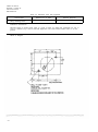
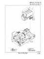
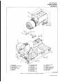
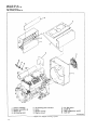
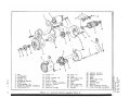
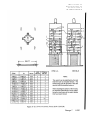
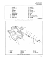
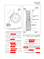
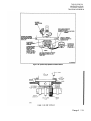
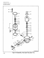
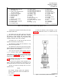
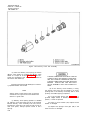
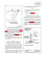
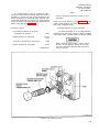
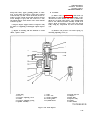
1
ARMY TECHNICAL MANUAL
TM5-6115-585-34
NAVY PUBLICATION
NAVFACP-8-262-12
AIR FORCE TECHNICAL ORDER
TO-35C2-3-455-2
MARINE CORPS TECHNICAL MANUAL
TM-05684C-34
TECHNICAL
INTERMEDIATE
AND
(FIELD)
DEPOT
MANUAL
(DIRECT
LEVEL
AND
GENERAL
MAINTENANCE
SUPPORT)
MANUAL
GENERATOR SET, DIESEL ENGINE DRIVEN, TACTICAL SKID MTD 10KW, 1 PHASE
-2 WIRE, 1 PHASE -3 WIRE,3PHASE -4 WIRE, 120, 120/240 AND 120/208 VOLTS
DOD MODEL
CLASS
HERTZ
NSN
MEP-003A
UTILITY
60
6115-00-465-1030
T h i s
c o p y
p a g e s
i s
f r o m
a
r e p r i n t
C h a n g e s
w h i c h
1
i n c l u d e s
t h r o u g h
c u r r e n t
9 .
PUBLISHED UNDER THE AUTHORITY OF THE DEPARTMENTS OF THE ARMY,
AIR FORCE, NAVY, AND HEADQUARTERS U.S. MARINE CORPS
JULY 1977
TM5-6115-585-34
NAVFAC P-8-262-12
TO-35C2-3-455-2
TM-05684C-34
WARNING
All specific cautions and warnings contained in this manual shall be strictly
adhered to. Otherwise, severe injury, death and/or damage to the equipment may
result.
HIGH VOLTAGE
is produced when this Generator Set is in operation.
DEATH
or severe burns may result if personnel fail to observe safety precautions. Do not
operate this Generator Set until the ground terminal stud has been connected to a
suitable ground. Disconnect the battery ground cable before removing and installing
components on the engine or in the electrical control panel system. Remove all
rings, watches, and other jewelry when performing maintenance on this equipment.
Loose fitting clothing should be secured to prevent it catching in moving parts. D O
not attempt to service or otherwise make any adjustments, connections or reconnection of wires or cables until Generator Set is shut-down and completely deenergized.
DANGEROUS GASES
Batteries generate explosive gas during charging: therefore, utilize extreme
caution, do not smoke, or use open flame in the vicinity of the Generator Set when
servicing batteries.
Exhaust discharge contains noxious and deadly fumes. Do not operate Generator
Sets in enclosed areas unless exhaust discharge is properly vented to the outside.
To avoid sparking between filler nozzle and fuel tank, always maintain metal to
metal contact between filler nozzle and fuel tank when filling fuel tank.
Do not smoke or use open flame in the vicinity of the Generator Set while fueling.
LIQUIDS UNDER HIGH PRESSURE
are generated as a result of operation of the Generator Set. Do not expose any
part of the body to a high pressure leak in the fuel injection system.
WARNING
Clean parts in a well-ventilated area. Avoid inhalation of solvent fumes and prolonged exposure of skin to cleaning solvent. Wash exposed skin thoroughly. Dry
cleaning solvent (Fed. Spec. P-D-680) used to clean parts is potentially dangerous
to personnel and property. Do not use near open flame or excessive heat. Flash
point of solvent is 100° F. to 138° F. (38° C. to 59° C.).
WARNING
If conditions require fuel tank repairs by welding or other methods involving heat
or flame, take care to assure that all fumes are purged from the tank or fill tank
with water before commencing the repair. If possible, tank should be filled with
water prior to welding after being thoroughly purged of fumes. Applying heat or
flame to a fuel tank containing residue, may result in a violent explosion, causing
death or injury to maintenance personnel.
NOISE
Operating level of this generator can cause hearing damage. Ear protectors, as
recommended by the medical or safety officer, must be worn when working near
this set.
TM 5-6115-585-34
NAVFAC P-8-623-34
TO-35C2-3-455-2
TM-05684C/05685B-34
C9
HEADQUARTERS,
DEPARTMENTS OF THE ARMY, NAVY AND AIR FORCE
AND HEADQUARTERS U.S. MARINE CORPS
WASHINGTON, D. C., 4 MAY 1992
CHANGE
NO.
9
Intcrmediate (Field) (Direct and General Support)
and Depot Level Maintenance Manual
GENERATOR SET, DIESEL ENGINE DRIVEN, TACTICAL SKID MTD
10 KW, 1 PHASE-2 WIRE, 1 PHASE-3 WIRE, 3 PHASE-4 WIRE
120, 120/240 AND 120/208 VOLTS
DOD MODEL
CLASS
HERTZ
NSN
MEP-003A
MEP-112A
UTILITY
UTILITY
60
400
6115-00-465-1030
6115-00-465-1027
Approved for public release; distribution is unlimited
TM 5-6115–585–34/NAVFACP-8–623–34n0-35 C2-3-455-2/TM-05684C/05685B-34, 25 July 1977, is
changed as follows:
1. Remove and insert pages as indicated below. Page 1–10.1/(1–10.2 blank) was changed in Change 7;
however, the Change transmittal sheet inadvertently omitted instructions to remove the original page
1–10.1/(1-10.2 blank) before inserting the change page. The Change 7 page 1–10.1/(1–10.2 blank) also did not
include any change indicators or number. To eliminate any confusion, therefore, as to which page should be used,
the most current page is included in Change 9; the change indicated by the miniature pointing hand was included in
Change 7, but was not indicated by a pointing hand.
Remove pages
Insert pages
1–10.1/(1–10.2 blank)
1-10.1/(1–10.20 blank)
2. Retain this sheet in front of manual for reference purposes.
TM 5-6115-585-34
NAVFAC P-8-623-34
TO-35C2-3-455-2
TM-05684C/05685 B-34
C9
By Order of the Secretaries of the Army, Air Force, and Navy (Including the Marine Corps):
GORDON R. SULLIVAN
General, United States Army
Chief of Staff
Official:
Milton H. Hamilton
MILTON H. HAMILTON
Administrative Assistant to the
Secretary ot the Army
01110
MERRILL A. McPEAK
General USAF
Chief of Staff
Official:
CHARLES C. McDONALD
General, USAF
Commander, Air Force Logistics Command
DAVID E. BOTTORFF
Rear Admiral, CEC, US Navy
Commander
Navy Facilities Engineering Command
H.E. REESE
Deputy for Support
Marine Corps Research, Development and
Acquisition Command
DISTRIBUTION:
To be distributed in accordance with DA Form 12-25E, (qty rqr block no. 0870
20 March 1991
14 June 1989
16 April 1984
DEPARTMENT OF THE ARMY TECHNICAL MANUAL
DEPARTMENT OF THE NAVY PUBLICATION
DEPARTMENT OF THE AIR FORCE TECHNICAL ORDER
MARINE CORPS TECHNICAL MANUAL
TM5-6115-585-34
NAVFAC P-8-623-34
TO-35C2-3-455-2
TM-05684C/05685B-34
HEADQUARTERS
DEPARTMENTS OF THE ARMY, NAVY, AIR FORCE, & USMC
WASHINGTON, D.C. 25 JULY 1977
INTERMEDIATE (FIELD) (DIRECT AND GENERAL SUPPORT)
AND DEPOT LEVEL MAINTENANCE MANUAL
GENERATOR SET, DIESEL ENGINE DRIVEN, TACTICAL SKID MTD 10KW, 1 PHASE
-2 WIRE, 1 PHASE - 3 WIRE, 3 PHASE - 4 WIRE, 120, 120/240 AND 120/208 VOLTS
DOD MODEL
CLASS
HERTZ
NSN
MEP-003A
UTILITY
60
6115-00-465-1030
MEP-112A
UTILITY
400
6115-00-465-1027
TABLE OF CONTENTS
Page
CHAPTER 1.
Section
I.
LIST OF EFFECTIVE PAGES. . . . . . . . . . . . . . . .
LIST OF ILLUSTRATIONS . . . . . . . . . . . . . . . . .
LIST OF TABLES..... . . . . . . . . . . . . .
INTRODUCTION . . . . . . . . . . . . . . . . . . . . . . .
1-1
GENERAL . . . . . . . . . . . . . . . . . . . . . . . . . . . . . . .
1-1
1-1
1-1
1-1
1-1
1-1
DESCRIPTION AND TABULATED DATA . . . . . . . . . . . . . . .
1-1
Description. . . . . . . . . . . . . . . . . . . . . . . . . . .
Tabulated Data . . . . . . . . . . . . . . . . . . . . . . . . .
1-1
1-1
GENERAL MAINTENANCE INSTRUCTIONS . . . . . . . . . . . . .
2-1
REPAIR PARTS, SPECIAL TOOLS, TEST, MEASUREMENT, AND
D I A G N O S I C E Q U I P M E N T ( T M D E), AND S U P P O R T E Q U I P M E N T .
2-1
2-1.
2-2.
2-3.
Repair Parts . . . . . . . . . . . . . . . . . . . . . . . . . .
Tools and Equipment . . . . . . . . . . . . . . . . . . . . . .
Fabricated Tools and Equipment . . . . . . . . . . . . . . .
2-1
2-1
2-1
TROUBLESHOOTING . . . . . . . . . . . . . . . . . . . . . . . . .
2-5
2-4.
2-5.
2-5
1-6.
1-7.
CHAPTER 2.
Section
Section
I.
II.
.
.
.
.
.
.
.
.
.
.
.
.
.
.
.
.
.
.
.
.
.
.
.
.
.
vi
.
.
.
.
.
1-1.
1-2.
1-3.
1-4.
1-5.
Section II.
iv
v
. . . .
. . .
. . .
. . . .
Scope . . . . . . . . . . . . . . . . . . . . . . . .
Limited Applicability . . . . . . . . . . . . . . .
Maintenance Forms and Records . . . . . . . . .
Reporting of Errors . . . . . . . . . . . . . . . .
Levels of Maintenance Accomplishment . . . . .
.
.
.
.
General . . . . . . . . . . . . . . . . . . . . . . . . . . . . .
Malfunctions Not Corrected By Use of the Troubleshooting
Table . . . . . . . . . . . . . . . . . . . . . . . . . . . . .
2-5
Change
2
i
TM5-6115-585-34
NAVFAC P-8-262-12
TO-35C2-3-455-2
TM-05684C/05685B-34
TABLE OF CONTENTS (CONT)
Page
Section III.
Section IV.
CHAPTER 3.
Section
I.
Section II.
CHAPTER 4.
Section
I.
Section II.
CHAPTER 5.
Section
I.
Section II.
CHAPTER 6.
Section
Section
ii
I.
II.
GENERAL MAINTENANCE . . . . . . . . . . . . . . . . . . . . . .
2-12
2-6.
2-7.
General Maintenance . . . . . . . . . . . . . . . . . . . . . .
General Maintenance Procedures . . . . . . . . . . . . . . .
2-12
2-12
REMOVAL AND INSTALLATION OF MAJOR COMPONENTS . . . .
2-12
2-8.
Control Cubicle . . . . . . . . . . . . . . . . . . . . . . . .
2-9.
Engine Assembly . . . . . . . . . . . . . . . . . . . . . . . .
2-10. Generator Assembly . . . . . . . . . . . . . . . . . . . . . .
2-12
2-12
2-16
MAINTENANCE OF COOLING SYSTEM . . . . . . . . . . . . . . .
3-1
DESCRIPTION AND FUNCTION. . . . . . . . . . . . . . . . . . . .
3-1
3-1.
General . . . . . . . . . . . . . . . . . . . . . . . . . . . . .
3-1
MAINTENANCE . . . . . . . . . . . . . . . . . . . . . . . . . . . .
3-1
3-2.
3-3.
Engine Cooling System . . . . . . . . . . . . . . . . . . . .
High Temperature Cut Out Switch . . . . . . . . . . . . . .
3-1
3-1
MAINTENANCE OF FUEL SYSTEM . . . . . . . . . . . . . . . . .
4-1
DESCRIPTION AND FUNCTION. . . . . . . . . . . . . . . . . . . .
4-1
4-1.
General . . . . . . . . . . . . . . . . . . . . . . . . . . . . .
4-1
MAINTENANCE OF FUEL TANK. . . . . . . . . . . . . . . . . . .
4-1
4-2.
Fuel Tank . . . . . . . . . . . . . . . . . . . . . . . . . . .
4-1
MAINTENANCE OF STARTING SYSTEM . . . . . . . . . . . . . . .
5-1
DESCRIPTION AND FUNCTION.. . . . . . . . . . . . . . . . . . .
5-1
5-1.
General . . . . . . . . . . . . . . . . . . . . . . . . . . . . .
5-1
MAINTENANCE . . . . . . . . . . . . . . . . . . . . . . . . . . . .
5-1
5-2.
Starter Assembly . . . . . . . . . . . . . . . . . . . . . . . .
5-1
MAINTENANCE OF CONTROL SYSTEM . . . . . . . . . . . . . . .
6-1
DESCRIPTION AND FUNCTION. . . . . . . . . . . . . . . . . . . .
6-1
6-1.
6-2.
6-3.
DC Control System . . . . . . . . . . . . . . . . . . . . . . .
AC Instrumentation System . . . . . . . . . . . . . . . . . .
Voltage Regulator . . . . . . . . . . . . . . . . . . . . . . .
6-1
6-1
6-1
MAINTENANCE . . . . . . . . . . . . . . . . . . . . . . . . . . . .
6-1
6-4.
6-5.
6-6.
6-7.
6-8.
6-9.
6-1
6-8
6-8
6-9
6-9
6-9
Control Cubicle . . . . . . . . . . . . . . . . . . . . . . .
Generator Set Wiring Harness . . . . . . . . . . . . . . .
Voltage Regulator . . . . . . . . . . . . . . . . . . . . . .
AC Output Control Box Wiring Harness . . . . . . . . . . .
AC Output Control Box Assembly . . . . . . . . . . . . . .
AC Output Control Box (Internal Components) . . . . . . .
.
.
.
.
.
.
TM 5-6115-585-34
NAVFAC P-8-623-34
TO-35C2-3-455-2
TM-05684C/05685B-34
TABLE OF CONTENTS (CONT)
Page
CHAPTER 7.
MAINTENANCE OF ENGINE. . . . . . . . . . . . . . . . . . . . .
7-1
Section I.
DESCRIPTION AND FUNCTION. . . . . . . . . . . . . . . . . . . .
7-1
7-1.
General . . . . . . . . . . . . . . . . . . . . . . . . . . . . .
7-1
ENGINE EXTERNAL ASSEMBLY.. . . . . . . . . . . . . . . . . .
7-1
7-2.
7-3.
7-4.
7-5.
7-6.
7-7.
7-8.
Section II.
Section
III.
CHAPTER 8.
Section
I.
Section II
CHAPTER 9.
Section
I.
Section II.
Section III.
Fuel-Lines . . . . . . . . . . . . . . . . . . . . . . . . . .
External Governor Parts and Speed Control Assembly . . .
Flywheel and Ring Gear Assembly . . . . . . . . . . . . .
Flywheel Housing . . . . . . . . . . . . . . . . . . . . . .
Oil Cooler . . . . . . . . . . . . . . . . . . . . . . . . . .
Blower Wheel Assembly . . . . . . . . . . . . . . . . . . .
Battery Charge Alternator . . . . . . . . . . . . . . . . . . .
.
.
.
.
.
.
.
7-1
7-1
7-5
7-6
7-6
7-6
7-8
ENGINE INTERNAL ASSEMBLIES . . . . . . . . . . . . . . . .
7-8.1. Engine Compression Test . . . . . . . . . . . . . . . . . .
7-9.
Cylinder Head . . . . . . . . . . . . . . . . . . . . . . . .
7-10. Piston and Connecting Rod . . . . . . . . . . . . . . . . .
7-11. Oil Pump . . . . . . . . . . . . . . . . . . . . . . . . .
7-12. Oil Filter Adapter Assembly . . . . . . . . . . . . . . . .
7-13. Oil By-Pass Valve . . . . . . . . . . . . . . . . . . . . . .
7-14. Gear Cover Assembly. . . . . . . . . . . . . . . . . . . .
7-15. Governor Cup. . . . . . . . . . . . . . . . . . . . . . . .
7-16. Camshaft Assembly and Tappets . . . . . . . . . . . . . .
7-17. Crankshaft and Main Block Bearings . . . . . . . . . . . .
7-18. Fuel Injection Pump. . . . . . . . . . . . . . . . . . . . .
7-19. Cylinder Block . . . . . . . . . . . . . . . . . . . . . . . .
7-20. Fuel Injector . . . . . . . . . . . . . . . . . . . . . . . . .
.
.
.
.
.
.
.
.
.
.
.
.
.
.
7-9
7-9
7-10.1
7-13
7-19
7-19
7-19
7-21
7-25
7-25
7-27
7-30
7-41
7-41
MAINTENANCE OF GENERATOR ASSEMBLY . . . . . . . . . . . .
8-1
DESCRIPTION AND FUNCTION . . . . . . . . . . . . . . . . . . . .
8-1
8-1.
General . . . . . . . . . . . . . . . . . . . . . . . . . . . . .
8-1
MAINTENANCE . . . . . . . . . . . . . . . . . . . . . . . . . . . .
8-1
8-2.
Generator Maintenance . . . . . . . . . . . . . . . . . . . .
8-1
GENERATOR SET TEST AND INSPECTION AFTER REPAIR OR
OVERHAUL . . . . . . . . . . . . . . . . . . . . . . . . . . . . .
9-1
GENERAL REQUIREMENTS . . . . . . . . . . . . . . . . . . . . . .
9-1
9-1.
General Information . . . . . . . . . . . . . . . . . . . . . .
9-1
INSPECTION . . . . . . . . . . . . . . . . . . . . . . . . . . . . . .
9-1
9-2.
9-3.
9-4.
General . . . . . . . . . . . . . . . . . . . . . . . . . . . . .
Engine Cooling System . . . . . . . . . . . . . . . . . . . . .
Wiring Harnesses . . . . . . . . . . . . . . . . . . . . . . .
9-1
9-1
9-1
OPERATIONAL TEST . . . . . . . . . . . . . . . . . . . . . . . .
9-5.
Generator and Generator Control Circuitry . . . . . . . . . .
9-6.
Engine Control Circuitry . . . . . . . . . . . . . . . . . . . .
9-1
9-1
9-1
iii
TM 5-6115-585-34
NAVFAC P-8-623-34
TO-35C2-3-455-2
TM-05684C/05685B-34
TABLE OF CONTENTS (CONT)
Page
CHAPTER 1 0 .
Section I .
Section I I .
MATERIAL USED IN CONJUNCTION WITH DOD STANDARD
GENERATOR SET, 10KW DIESEL ENGINE, MODEL
MEP-003A AND MEP-112A . . . . . . . . . . . . . . . . . . . . . . . . . . . . . .
10-1
AUXILIARY EQUIPMENT . . . . . . . . . . . . . . . . . . . . . . . . . . . . . . . .
10-1
10-1. General . . . . . . . . . . . . . . . . . . . . . . . . . . . . . . . . . . . . . . . .
10-1
ACOUSTIC SUPPRESSION KIT INSTALLATION . . . . . . . . . . . . . . . . .
10-2
.
.
.
.
10-2
10-5
10-5
10-16
REFERENCE . . . . . . . . . . . . . . . . . . . . . . . . . . . . . . . . . . . . . . . . .
A-1
...................................................
INDEX 1
10-2.
10-3.
10-4.
10-5.
APPENDIX A .
INDEX
iv
. . . . .
Change 6
Acoustic Suppression Kit. . . . . . . . . . . . . . . . .
Preliminary Procedures. . . . . . . . . . . . . . . . . .
Acoustic Suppression Kit Installation . . . . . . . . .
Post Installation Procedures . . . . . . . . . . . . . . .
......
. . . . .
. . . . .
. . . . .
.
.
.
.
......
. . . . .
. . . . .
. . . . .
TM 5-6115-585-34
NAVFAC P-8-623-34
TO-35C2-3-455-2
TM-05684C/05685B-34
LIST OF ILLUSTRATIONS
Figure
l–l.
1–1.1
2–1.
2-2.
2-3.
2-4.
3-1.
5-1.
5-2.
5-3.
5-4.
5-5.
5-6.
5-7.
5-8.
5-9.
5-10.
5-11.
5–12.
5-13.
5-14.
6-1.
6-2.
6-3.
6-4.
6-5.
6-5.1.
6-6.
6-6.1.
6-7.
6-8.
6-9.
6-10.
6-11.
7-1.
7-2.
7-3.
7-3.1.
7-4.
7-5.
7-6.
7-7.
7–8.
7-8.1.
7-9.
7-10.
7-11.
7-12.
7-13.
7-14.
7-15.
7-16.
7-17.
7-18.
7-19.
7-20.
7-21.
Page
Title
Generator Set Electrical Schematic (MEP-003A) . . . . . . . . . . . . . . . . . . . . . . . . . . . . . . . . .
Generator Set Electrical Schematic (MEP-l12A) . . . . . . . . . . . . . . . . . . . . . . . . . . . . . . . . .
Speed Control Assembly . . . . . . . . . . . . . . . . . . . . . . . . . . . . . . . . . . . . . . . . . . . . . . . . . . . .
Disconnecting Engine from Generator . . . . . . . . . . . . . . . . . . . . . . . . . . . . . . . . . . . . . . . . . .
Lifting Engine . . . . . . . . . . . . . . . . . . . . . . . . . . . . . . . . . . . . . . . . . . . . . . . . . . . . . . . . . . . . .
Lifting Engine and Generator Assembly . . . . . . . . . . . . . . . . . . . . . . . . . . . . . . . . . . . . . . . .
Engine Cooling System . . . . . . . . . . . . . . . . . . . . . . . . . . . . . . . . . . . . . . . . . . . . . . . . . . . . .
Electric Starter Assembly (STYLE I). . . . . . . . . . . . . . . . . . . . . . . . . . . . . . . . . . . . . . . . . . .
Electric Starter Assembly (STYLEII) . . . . . . . . . . . . . . . . . . . . . . . . . . . . . . . . . . . . . . . . . .
Pinion Gear Stopper Removal. . . . . . . . . . . . . . . . . . . . . . . . . . . . . . . . . . . . . . . . . . . . . . . . .
Testing Armature for Grounds . . . . . . . . . . . . . . . . . . . . . . . . . . . . . . . . . . . . . . . . . . . . . . . .
Testing Armature for Shorted Coils . . . . . . . . . . . . . . . . . . . . . . . . . . . . . . . . . . . . . . . . . . . .
Testing Armature for Open Coils . . . . . . . . . . . . . . . . . . . . . . . . . . . . . . . . . . . . . . . . . . . . . .
Checking Commutator Runout. . . . . . . . . . . . . . . . . . . . . . . . . . . . . . . . . . . . . . . . . . . . . . .
Checking Armature Shaft Runout . . . . . . . . . . . . . . . . . . . . . . . . . . . . . . . . . . . . . . . . . . . . .
Testing Brush Spring Tension STYLE I Starter Only . . . . . . . . . . . . . . . . . . . . . . . . . . . . . .
Testing Solenoid Switch . . . . . . . . . . . . . . . . . . . . . . . . . . . . . . . . . . . . . . . . . . . . . . . . . . . . .
Undercutting Mica . . . . . . . . . . . . . . . . . . . . . . . . . . . . . . . . . . . . . . . . . . . . . . . . . . . . . . . . . .
Brush Replacement STYLE I Starter Only . . . . . . . . . . . . . . . . . . . . . . . . . . . . . . . . . . . . . .
Checking Pinion Clearance STYLE I Starter Only . . . . . . . . . . . . . . . . . . . . . . . . . . . . . . . .
Checking Pinion Clearance STYLE II Starter . . . . . . . . . . . . . . . . . . . . . . . . . . . . . . . . . . . . .
Control Cubicle Wiring Harness . . . . . . . . . . . . . . . . . . . . . . . . . . . . . . . . . . . . . . . . . . . . . .
Generator Set Wiring Harness . . . . . . . . . . . . . . . . . . . . . . . . . . . . . . . . . . . . . . . . . . . . . . . .
Control Cubicle . . . . . . . . . . . . . . . . . . . . . . . . . . . . . . . . . . . . . . . . . . . . . . . . . . . . . . . . . . . .
Testing Voltage Regulator . . . . . . . . . . . . . . . . . . . . . . . . . . . . . . . . . . . . . . . . . . . . . . . . . . .
AC Voltage Regulator Schematic (MEP-003A) . . . . . . . . . . . . . . . . . . . . . . . . . . . . . . . . . . .
AC Voltage Regulator Schematic (MEP-112A) . . . . . . . . . . . . . . . . . . . . . . . . . . . . . . . . . . .
AC Output Control Box Wiring Harness (MEP-003A) . . . . . . . . . . . . . . . . . . . . . . . . . . . .
AC Output Control Box Wiring Harness (MEP-112A) . . . . . . . . . . . . . . . . . . . . . . . . . . . . .
AC Output Control Box Test Setup . . . . . . . . . . . . . . . . . . . . . . . . . . . . . . . . . . . . . . . . . . . .
AC Control Box Removal . . . . . . . . . . . . . . . . . . . . . . . . . . . . . . . . . . . . . . . . . . . . . . . . . . .
AC Output Control Assembly . . . . . . . . . . . . . . . . . . . . . . . . . . . . . . . . . . . . . . . . . . . . . . . .
AC Output Control Assembly (Switch, Receptacle and Circuit Breaker) . . . . . . . . . . . . . . .
Bridge Rectifier AssemblyA-4 . . . . . . . . . . . . . . . . . . . . . . . . . . . . . . . . . . . . . . . . . . . . . . .
Injector FueI Lines . . . . . . . . . . . . . . . . . . . . . . . . . . . . . . . . . . . . . . . . . . . . . . . . . . . . . . . . .
Speed Control Assembly and Governor Control Assembly . . . . . . . . . . . . . . . . . . . . . . . . . .
Engine Flywheel and Ring Gear Assembly . . . . . . . . . . . . . . . . . . . . . . . . . . . . . . . . . . . . . .
Governor Linkage Adjustment . . . . . . . . . . . . . . . . . . . . . . . . . . . . . . . . . . . . . . . . . . . . . . . .
Timing Port and Port Closing Mark . . . . . . . . . . . . . . . . . . . . . . . . . . . . . . . . . . . . . . . . . . . .
Measuring Top Dead Center.. . . . . . . . . . . . . . . . . . . . . . . . . . . . . . . . . . . . . . . . . . . . . . . . .
Testing Oil Cooler . . . . . . . . . . . . . . . . . . . . . . . . . . . . . . . . . . . . . . . . . . . . . . . . . . . . . . . . .
Battery Charge Alternator and Blower Wheel . . . . . . . . . . . . . . . . . . . . . . . . . . . . . . . . . . . .
Resistively Loading the Batteries . . . . . . . . . . . . . . . . . . . . . . . . . . . . . . . . . . . . . . . . . . . . . .
Testing Engine Compression . . . . . . . . . . . . . . . . . . . . . . . . . . . . . . . . . . . . . . . . . . . . . . . . .
Cylinder Head Removal . . . . . . . . . . . . . . . . . . . . . . . . . . . . . . . . . . . . . . . . . . . . . . . . . . . . . .
Valve Spring Removal . . . . . . . . . . . . . . . . . . . . . . . . . . . . . . . . . . . . . . . . . . . . . . . . . . . . . .
Cylinder Head Assembly . . . . . . . . . . . . . . . . . . . . . . . . . . . . . . . . . . . . . . . . . . . . . . . . . . .
Valve Seat Replacement . . . . . . . . . . . . . . . . . . . . . . . . . . . . . . . . . . . . . . . . . . . . . . . . . . . . .
Cylinder Head Bolt Tightening Sequence . . . . . . . . . . . . . . . . . . . . . . . . . . . . . . . . . . . . . . .
Piston and Connecting Rod . . . . . . . . . . . . . . . . . . . . . . . . . . . . . . . . . . . . . . . . . . . . . . . . . .
Crankshaft Pistons and Connecting Rod . . . . . . . . . . . . . . . . . . . . . . . . . . . . . . . . . . . . . . . .
Piston Ring Installation . . . . . . . . . . . . . . . . . . . . . . . . . . . . . . . . . . . . . . . . . . . . . . . . . . . . . .
Connecting Rod and Bushings . . . . . . . . . . . . . . . . . . . . . . . . . . . . . . . . . . . . . . . . . . . . . . . .
Connecting Rod Installation . . . . . . . . . . . . . . . . . . . . . . . . . . . . . . . . . . . . . . . . . . . . . . . . . .
Oil Pump Removal . . . . . . . . . . . . . . . . . . . . . . . . . . . . . . . . . . . . . . . . . . . . . . . . . . . . . . . . .
Oil Bypass Valve . . . . . . . . . . . . . . . . . . . . . . . . . . . . . . . . . . . . . . . . . . . . . . . . . . . . . . . .
Internal Engine Assembly..... . . . . . . . . . . . . . . . . . . . . . . . . . . . . . . . . . . . . . . . . . . . . . . .
1-9
1-10.1
2-13
2-14
2-15
2-17
3-2
5-2
5-3
5-4
5-5
5-5
5-5
5-6
5-6
5-7
5-8
5-10
5-10
5-11
5-12
6-2
6-6
6-10
6-12
6-13
6-14
6-14.1
6-14.2
6-15
6-16.2
6-19
6-20
6-21
7-2
7-3
7-4
7-5
7-5
7-6
7-6
7-7
7-8
7-10
7-10.2
7-11
7-12
7-13
7-14
7-15
7-16
7-17
7-18
7-19
7-20
7-21
7-22
Change 8
v
TM 5-6115-585-34
NAVFAC P-8-623-34
TO-35C2-3-455-2
TM-05684C/05685B-34
Figure
7–22.
7–23.
7-24.
7-25.
7-26.
7-27.
7-28.
7-29.
7-30.
7-31.
7-32.
7–33.
7-34.
7-35.
7-36.
7–37.
7-38.
7–39.
7-40.
7-41.
7-42.
7-43.
7-44.
7-45.
7-46.
7-47.
8-1.
8-2.
8-3.
8-4.
8-5.
9-1.
9-2.
10-1.
10-2.
10-3.
10-4.
10-5.
10-6.
LIST OF ILLUSTRATIONS (CONT)
Title
Gear CoverComponents . . . . . . . . . . . . . . . . . . . . . . . . . . . . . . . . . . . . . . . . . . . . . . . . . . . . .
Gear Cover Inspection . . . . . . . . . . . . . . . . . . . . . . . . . . . . . . . . . . . . . . . . . . . . . . . . . . . . . .
Governor Cup Assembly . . . . . . . . . . . . . . . . . . . . . . . . . . . . . . . . . . . . . . . . . . . . . . . . . . . .
Camshaft Bearing Installation . . . . . . . . . . . . . . . . . . . . . . . . . . . . . . . . . . . . . . . . . . . . . . . .
Crankshaft and Camshaft Gear Timing Marks . . . . . . . . . . . . . . . . . . . . . . . . . . . . . . . . . . . .
Timing Gear Backlash . . . . . . . . . . . . . . . . . . . . . . . . . . . . . . . . . . . . . . . . . . . . . . . . . . . . . .
Crankshaft Gear Removal . . . . . . . . . . . . . . . . . . . . . . . . . . . . . . . . . . . . . . . . . . . . . . . . . . . .
Crankshaft Peening . . . . . . . . . . . . . . . . . . . . . . . . . . . . . . . . . . . . . . . . . . . . . . . . . . . . . . . . .
Crankshaft Bearing Installation . . . . . . . . . . . . . . . . . . . . . . . . . . . . . . . . . . . . . . . . . . . . . . .
Crankshaft End Play Measurement . . . . . . . . . . . . . . . . . . . . . . . . . . . . . . . . . . . . . . . . . . . .
Injection Pump . . . . . . . . . . . . . . . . . . . . . . . . . . . . . . . . . . . . . . . . . . . . . . . . . . . . . . . . . . . .
Injection Pump Adjustment and Button Removal . . . . . . . . . . . . . . . . . . . . . . . . . . . . . . . . .
Disassembly of Fuel Injection Pump . . . . . . . . . . . . . . . . . . . . . . . . . . . . . . . . . . . . . . . . . . .
Removing Lower Spring Seat . . . . . . . . . . . . . . . . . . . . . . . . . . . . . . . . . . . . . . . . . . . . . . . . .
Delivery Valve Test Assembly . . . . . . . . . . . . . . . . . . . . . . . . . . . . . . . . . . . . . . . . . . . . . . . .
Inspecting Tappet . . . . . . . . . . . . . . . . . . . . . . . . . . . . . . . . . . . . . . . . . . . . . . . . . . . . . . . . . .
Assembling Hydraulic Head. . . . . . . . . . . . . . . . . . . . . . . . . . . . . . . . . . . . . . . . . . . . . . . . . .
Control Unit Assembly . . . . . . . . . . . . . . . . . . . . . . . . . . . . . . . . . . . . . . . . . . . . . . . . . . . . . .
Checking Plunger Sleeve Alignment . . . . . . . . . . . . . . . . . . . . . . . . . . . . . . . . . . . . . . . . . .
Pressure Testing Injection Pump . . . . . . . . . . . . . . . . . . . . . . . . . . . . . . . . . . . . . . . . . . . . . .
Injection Pump Installation . . . . . . . . . . . . . . . . . . . . . . . . . . . . . . . . . . . . . . . . . . . . . . . . . . .
Delivery Valve . . . . . . . . . . . . . . . . . . . . . . . . . . . . . . . . . . . . . . . . . . . . . . . . . . . . . . . . . . . .
Timing Port and Port Closing Mark . . . . . . . . . . . . . . . . . . . . . . . . . . . . . . . . . . . . . . . . . . . .
Injector Nozzle Removal . . . . . . . . . . . . . . . . . . . . . . . . . . . . . . . . . . . . . . . . . . . . . . . . . . . .
Fuel Injector . . . . . . . . . . . . . . . . . . . . . . . . . . . . . . . . . . . . . . . . . . . . . . . . . . . . . . . . . . . . . .
Centering Sleeve Installation . . . . . . . . . . . . . . . . . . . . . . . . . . . . . . . . . . . . . . . . . . . . . . . . .
Generator Exploded View . . . . . . . . . . . . . . . . . . . . . . . . . . . . . . . . . . . . . . . . . . . . . . . . . . .
Testing Exciter Rotor . . . . . . . . . . . . . . . . . . . . . . . . . . . . . . . . . . . . . . . . . . . . . . . . . . . . . .
Generator Frame Assembly Winding Data . . . . . . . . . . . . . . . . . . . . . . . . . . . . . . . . . . . . . . .
Exciter Rotor Assembly Winding Data . . . . . . . . . . . . . . . . . . . . . . . . . . . . . . . . . . . . . . . . .
Generator Rotor Winding Data. . . . . . . . . . . . . . . . . . . . . . . . . . . . . . . . . . . . . . . . . . . . . . . .
Adjusting R3 Resistor . . . . . . . . . . . . . . . . . . . . . . . . . . . . . . . . . . . . . . . . . . . . . . . . . . . . . . .
Testing Engine Control Circuitry . . . . . . . . . . . . . . . . . . . . . . . . . . . . . . . . . . . . . . . . . . . . . .
Relocation of Trailer Items to Accomodate ASK Modification . . . . . . . . . . . . . . . . . . . . . . .
Installation of Right Support, Rear Panel, and Rear Flap Assemblies . . . . . . . . . . . . . . . . . .
Installation of Left Support Assembly . . . . . . . . . . . . . . . . . . . . . . . . . . . . . . . . . . . . . . . . . . .
Installation of Rear Closure Assembly and Exhaust Plenum Asscmblies . . . . . . . . . . . . . . .
Installation of Right Panel Assembly . . . . . . . . . . . . . . . . . . . . . . . . . . . . . . . . . . . . . . . . . . .
Installation of Left Panel, Side Closure, Front Panel and Top Panel Assemblies . . . . . . . . .
Page
7-23
7-24
7-25
7-26
7-27
7-27
7-28
7-28
7-29
7-29
7-30
7–31
7-32
7-33
7-34
7-35
7-35
7-36
7-37
7-37
7-38
7-39
7-40
7-42
7-43
7-44
8-2
8-5
8-7
8-9
8-11
9-2
9-2
10-4
10-4
10-8
10-11
10-13
10-14
Table
1-1.
1-2.
2-1.
2-2.
2-3.
6-1.
6-2.
6-3.
6-3.1.
6-4.
6-5.
6-6.
7-1.
9-1.
10-1.
LIST OF TABLES
Title
Torque Values (Ft-Lb) . . . . . . . . . . . . . . . . . . . . . . . . . . . . . . . . . . . . . . . . . . . . . . . . . . . . . .
Repair and Replacement Standards . . . . . . . . . . . . . . . . . . . . . . . . . . . . . . . . . . . . . . . . . . . .
Special Tools, Test and Support Equipment . . . . . . . . . . . . . . . . . . . . . . . . . . . . . . . . . . . . .
Fabricated Tools and Equipment . . . . . . . . . . . . . . . . . . . . . . . . . . . . . . . . . . . . . . . . . . . . . .
Troubleshooting . . . . . . . . . . . . . . . . . . . . . . . . . . . . . . . . . . . . . . . . . . . . . . . . . . . . . . . . . . .
Control Cubicle Wiring Harness . . . . . . . . . . . . . . . . . . . . . . . . . . . . . . . . . . . . . . . . . . . . . .
10KW Generator Set Wiring Harness . . . . . . . . . . . . . . . . . . . . . . . . . . . . . . . . . . . . . . . . . .
AC Output Control Box Wiring Harness (MEP-003A only) . . . . . . . . . . . . . . . . . . . . . . . . .
AC Output Control Box Wiring Harness (MEP-112Aonly) . . . . . . . . . . . . . . . . . . . . . . . . .
Terminal Voltages . . . . . . . . . . . . . . . . . . . . . . . . . . . . . . . . . . . . . . . . . . . . . . . . . . . . . . . . . .
Reconnection Switch Continuity . . . . . . . . . . . . . . . . . . . . . . . . . . . . . . . . . . . . . . . . . . . . . .
Testing Bridge Assembly (60 Hz only) . . . . . . . . . . . . . . . . . . . . . . . . . . . . . . . . . . . . . . . . . .
Button Code Letter and Size. . . . . . . . . . . . . . . . . . . . . . . . . . . . . . . . . . . . . . . . . . . . . . . . . .
Test Schedule . . . . . . . . . . . . . . . . . . . . . . . . . . . . . . . . . . . . . . . . . . . . . . . . . . . . . . . . . . . . .
Acoustic Suppression Kit Parts and Required Hardware . . . . . . . . . . . . . . . . . . . . . . . . . . . .
Page
1-3
1-4
2-1
2-2
2-4
6-3
6-5
6-7
6-8.1
6-9
6-15
6-17
7-40
9-2
10-2
vi
Change 8
TM5-6115-585-34
NAVFAC P-8-262-12
TO-35C2-3-455-2
TM-05684C/05685B-34
CHAPTER 1
INTRODUCTION
Section I. GENERAL
1-1. SCOPE.
1-4. REPORTING OF ERRORS.
This manual is for your use in maintaining the DOD
Standard Generator Set, 10KW Diesel Engine Driven,
Models MEP-003A and MEP-112A. It contains sections for general maintenance, including troubleshooting, and removal and installation of major
components, and maintenance of individual components
of the unit. Thoroughly familiarize yourself with the
unit before servicing or repairing unit.
Report of errors, omissions, and recommendations
for improvement of this publication by the individual
user is encouraged. Reports should be submitted as
follows:
a. (A) Army - DA Form 2028 directly to: Commander, US Army Troop Support and Aviation
Materiel Readiness Command,
ATTN: DRSTSMTT, 4300 Goodfellow Boulevard, St. Louis, MO 63120.
1-2. LIMITED APPLICABILITY.
b, (F) Air Force - AFTO Form 22 directly to:
Commander, Sacramento Air Logistics Center, ATTN:
Some portions of this publication are not applicable
to all services. These portions are prefixed to indicate
the services to which they pertain: (A) for Army,
(F) for Air Force, (N) for Navy, and (MC) for Marine
Corps. Portions not prefixed are applicable to all
services.
MMEDT, McClellan Air Force Base, CA 95652, in
accordance with TO-00-5-1.
c. (N) Navy - by letter directly to: Commanding
officer, US Navy, Ships Parts Control Center, ATTN:
Code 783, Mechanicsburg, PA 17055.
1-3. MAINTENANCE FORMS AND RECORDS.
d. (MC) Marine Corps - by NAVMC form 10772
directlv to: Commandant. US Marine Corps, ATTN:
Code L-MA-l, WASH DC 20380.
a. (A) Maintenance forms and records used by
Army personnel are prescribed in TM 38-750.
b. (F) Maintenance forms and records used by Air
Force personnel are prescribed in AFM-66-1 and the
applicable 00-20 Series Technical Orders.
c. (N) Navy users should refer to their service
peculiar directives to determine applicable maintenance forms and records to be used.
d. (MC) Maintenance forms and records used by
Marine Corps personnel are prescribed in TM 470015/ 1.
1-5. LEVELS OF MAINTENANCE ACCOMPLISHMENT.
a. (A, MC) Army and Marine Corps users shaIl
refer to the Maintenance Allocation Chart (MAC) for
tasks and levels of maintenance to be performed.
b. (F) Air Force users shall accomplish maintenance at the user level consistent with their capability
in accordance with policies established in AFM 66-1.
c. (N) Navy users shall determine their maintenance
levels in accordance with their service directives.
Section II. DESCRIPTION AND TABULATED DATA
1-6. DESCRIPTION.
1-7. TABULATED DATA.
A general description of the Diesel Engine Generator
Sets and information pertaining to the identification
plates are contained in the Operator and
Organizational Maintenance Manual. Detailed
descriptions of the components of the Diesel Engine
Generator Sets are provided in the applicable
maintenance paragraphs of this manual.
a. General. This paragraph contains all maintenance
data pertinent to intermediate (field) (direct, general
support) and depot maintenance personnel.
b. Engine Generator Sets. Refer to Operator and
Organizational Maintenance Manual.
Change 2
1-1
TM5-6115-585-34
NAVFAC P-8-623-34
TO-35C2-3-455-2
TM-05684C/05685B-34
c. Main Generator. Exciter field voltage andcurrent
versus load, see the following:
Exciter
Percent of Rated Load
10-.8PF, 120 V
Volts
Amps
0.96
o
17.8
25
21.7
0.56
50
25.5
0.66
0.77
75
29.8
0.87
100
34.0
1.0
125
38.7
d. Generator Frame Assembly.
Model . . . . . . . . . . . . . . . . . . . .MEP-003A
DOD Drawing No. . . . . . . . . . . . 72-5270
Number of Slots ........ . . . ...60
Pitch of Coil . . . . . . . . . . . . . . . . 1-11
Coil Groups . . . . . . . . . . . . . . ...12
Coils per Group . . . . . . . . . . . . . ...5
Turns per Coil Group . . . . . . . 5-5-5-5-5
Conductor . . . . . . . . . . . 8 strands of #18
AWG magnet wire
Resistance between lead. . . 0.115 ± 0.012 ohms
pairs T 1 - T4 , T2 - T5 , T3 - T6
T 7 - T1 0, T 8 - T11 a n d T9 - T1 2
at 25°C (87°F)
Model . . . . . . . . . . . . . . . . . . . .MEP-l12A
DOD Drawing No. . . . . . . . . . . . . . . 72-5272
Number of Slots . . . . . . . . . . . . . . . . . . . 108
Pitch of Coil . . . . . . . . . . . . . . . . . . . . . 1-4
Turns per Coil . . . . . . . . . . . . . . . . . . ...2
Conductor . . . . . . . . . . . . . . . 5strandsof #18
AWG magnet wire
Resistance between lead . . . 0.071± 0.007 ohms
pairs T 1 - T4 , T2 - T5 , T3 - T6 ,
T 7 - T1 0, T8 - T1l a n d T9 - T1 2
at 25° C
e. Generator Rotor.
Model . . . . . . . . . . . . . . . . . . ..,MEP-003A
DOD Drawing No. . . . . . . . . . . . 72-5265
Air Gap . . . . . . . . . . . . ..0.090 to 0.106 in.
Number of Poles . . . . . . . . . . . . . . .4
Turns per Pole . . . . . . . . . . . . . . . 207
Conductor . . . . . . . . . . . . 1 strand of #14
AWG magnet wire
Connection . . . . . . . . . . . . . .. series
Resistance of Connected . . . 3.31 ± 0.33 ohms
Poles at 25° C (77° F)
Model . . . . . . . . . . . . . . . . . . . MEP-112A
DOD Drawing No. . . . . . . . . . . . . . . 72-5267
Air Gap . . . . . . . . . . . . . .. 0.030 to 0,048 in.
Number of Poles . . . . . . . . . . . . . . . . .. .24
Turns per Pole . . . . . . . . . . . . . . . . . . .55
Conductor . . . . . . . . . . . . .. 4 strands of #18
AWG magnet wire
Resistance of Connected . . .. 3.05 ± 0.305 ohms
Poles at 250° C
1-2
Change 2
f. Engine. Refer to Operator and Organizational
Maintenance Manual.
g.
Exciter Assembly.
MEP-003A MEP-112A
± 6.0
± 1.8
Frequency Regula- . .
tion, Hz
± 1.2
± 4.0
Short Term . . . . . . .
Steady State, Hz
Stability (30 sec)
± 6.0
±1.8
Long Term . . . . . . .
Steady State, Hz
Stability (4 hrs)
± 4.0
± 1.2
Frequency Drift . . . .
(8 Hr period), Hz
h. Exciter Stator.
DOD Drawing No. . . . . . . . . . . . 72-5240
Number of Poles ....... . . . . ...8
Turns per coil . . . . . . . . . . . . ...400
Conductor . . . . . . . . . . . . l stand of #23
AWG magnet wire
Connection . . . . . . . . . . . . . .. series
Resistance at 25° C (87° F) . . 36.0 ± 3.6 ohms
i. Exciter Rotor.
DOD Drawing No. . . . . . . . . . . . 72-5220
Air Gap . . . . . . . . . . . . . . .052 to .064
Number of Slots . . . . . . . . . . . . . ..36
1-4
Pitch of Coil . . . . . . . . . . . . . . . .
Coil Groups . . . . . . . . . . . . . ..24
Coils per Group . . . . . . . . . . . . . ..2-1
Turns per Coil . . . . . . . . . . . . . ..11
Conductor . . . . . . . . . . . 1 strand of #17
AWG magnet wire
Resistance between . . . . . 0.677 ± 0.068 ohms
T 1 - T2 , T2 - T3 and T 1 - T3
at 25°C (87°F)
j. Circuit Breaker.
DOD Drawing No. . . . . (MEP-003A) 72-5173
(MEP-112A) 72-5174
Construction
Handle Spacers . . . . . . . . . . . aluminum
Handle Tie Bars . . . . . . . . . . aluminum
Mounting Insert . . . . . . . . . . . . . steel
Washer . . . . . . . . . . . . external tooth
Studs . . . . . . . . . . brass with silver or
tin plated
Handle Tie Pin . . . . . corrosion resistant
steel
Type . . . . . . . . . . . . . . . . . . relay trip
Voltage . . . . . . . . . . . . . . ..250 vac
Frequency . . . . . . . . (MEP-003A) 60 Hz
(MEP-112A) 400 Hz
Interrupting Capacity . . . . . . . . . . . 5000A
Relay Coil . . . . . . . . . . . . . calibrated to
carry 0.82A
Trip . . . . . . . . . . . . . 1.13A 6 ± 3 min
Trip . . . . . . . . . . 3.00A instantaneously
Maximum Contact Capacity . . . . . . . . 104A
Temperature Range . . . . . . . 54° C thru 85° C
129° F thru 185° F
TM5-6115-585-34
NAVFAC P-8-623-34
TO-35C2-3-455-2
TM-05684C/05685B-34
k. Engine Accessories.
(1) Fuel injection pump.
Manufacturer . . . . . . . . . . . . .. Onan
Model . . . . . . . . . . . . . . . .147-0333
Type . . . . . . . . . . PSU, single plunger
multi outlet
Drive Type . . . . . . . . . . . .gear and cam
Mounting . . . . . . . . . . . block mounted
(4) Battery charging alternator. Refer to Operator
and Organizational Maintenance Manual.
(5) Fuel solenoid valve.
DOD Drawing No. . . . . . . . . . . . 72-5069
volts . . . . . . . . . . . . . . . . . 24 vdc
Watts . . . . . . . . . . . . . . . . . . 12 w
Input Pressure . . . . . . . . . . . ..20 psi
Orifice Size . . . . . . . . . . . . . 0.187 inch
(2) Fuel transfer pumps. Refer to Operator and
Organizational Maintenance Manual.
(6) Oil pump.
(3) Electric starter. Refer to Operator and
Organizational Maintenance Manual.
Type . . . . . . . . . . . . . . .
gear driven
1. Acoustic Suppression Kit.
Manufacturer . . . . . . . . . . . . . . . . . . .IAC
Model . . . . . . . . . . . . . . . . . . . MEP-003AAS
Type . . . . . . . . . . . . . . . .
sound absorptive
cover
Change 6
1-2.1/(1-2.2 blank)
TM5-6115-585-34
NAVFAC P-8-623-34
TO-35C2-3-455-2
TM-05684C/05685B-34
Table 1-1. Torque Values (Ft-Lb Dry)
Torque Range (Cadmium Plated) (Ft-Lb Dry)
Item
Min.
Max.
Connecting rod bolt . . . . . . . . . . . . . .
27
29
Cover-rocker box . . . . . . . . . . . . . .
7
8
Exhaust manifold nuts . . . . . . . . . . . .
11*
13*
Flywheel mounting screw . . . . . . . . . . .
54
58
Gearcase cover . . . . . . . . . . . . . . . .
15
17
Rear bearing plate . . . . . . . . . . . . . .
40**
45**
Rocker arm nut (prevailing torque locknut).
4***
10***
Rocker arm stud . . . . . . . . . . . . . . .
35
40
Oil pump mounting screws . . . . . . . . . .
13
17
Oil base mounting screws . . . . . . . . . .
42****
47****
Oil filter base mounting screws . . . . . . .
18
20
Cylinder head bolt . . . . . . . . . . . . . .
44*
46*
Oil cooler mounting screws . . . . . . . . .
20
22
Blower wheel mounting screw . . . . . . . .
65
70
Intake manifold mounting screws . . . . . .
13
15
Injector nozzle mounting screws . . . . . . .
17
18
Glow plug . . . . . . . . . . . . . . . . . . .
10*
15*
Governor arm locking screw . . . . . . . . .
Damper blower wheel assembly nut . . . . .
Backplate screw (hex-socket flathead) . . . .
Center main bolt . . . . . . . . . . . . . . .
High temperature cutout switch . . . . . . .
32 (in. lb.)
28
75 (in. lb.)
97
50 (in. lb.)
36 (in. lb.)
30
85 (in. lb.)
102
60 (in. lb.)
Fuel supply line nut
Fuel return line fitting*****
16
18
Anti Seize Compound.
Apply MIL-S-22473C, Grade CV, to threads.
Torque specifications to be used only to determine if used locknuts meet new part tolerances.
Torque these screws twice.
Tighten to 1/6 turn beyond a hand tightened snug fit.
Change 6
1-3
TM 5-6115-585-34
NAVFAC P-8-623-34
TO-35C2-3-455-2
TM-05684C/05685B-34
Table 1-1. Torque Values (Ft-Lb Dry) (Cont’d)
Torque Range (Cadmium Plated) (Ft-Lb Dry)
Item
Acoustic Suppression Kit
Right Support Assembly Mounting Screws . . . .
Left Support Assembly Mounting Screws . . . . .
Rear Panel Assembly Mounting Screws . . . . . .
Rear Flap Assembly Mounting Screws . . . . . . .
Rear Closure Assembly Mounting Screws . . . . .
Side Closure Assembly Mounting Screws . . . . .
Exhaust Plenum Assembly Mounting Screws . .
Left Panel Assembly
Support Mounting Screws . . . . . . . . . . . . . .
Side Closure Mounting Screws . . . . . . . . . .
Right Panel Assembly
Support Mounting Screws . . . . . . . . . . . . . .
Rear Closure Mounting Screws . . . . . . . . . .
Rear Panel Mounting Screws . . . . . . . . . . .
Front Panel Assembly Mounting Screws . . . . .
Top Panel Assembly
Side & Rear Closure Mounting Screws . . . .
Left, Right & Front Panel
Mounting Screws . . . . . . . . . . . . . . . . . . .
1-4
Change
6
Min.
Max.
24
24
14
14
14
14
28
28
18
18
18
18
18
16 (in. lb.)
14
20 (in. lb.)
18
16 (in. lb.)
14
16 (in. lb.)
16 (in. lb.)
20 (in. lb.)
18
20 (in. lb.)
20 (in. lb.)
14
18
16 (in. lb.)
20 (in. lb.)
14
TM 5-6115-585-34
NAVFAC P-8-623-34
TO-35C2-3-455-2
TM-05684C/05685B-34
Table 1-2. Repair and Replacement Standards
(All values in inches unless otherwise specified.)
Manufacturer Dimensions
and Tole r a n c e s
Component
Minimum
Maximum
Maximum Allowable
Wear Limit
CYLINDER BLOCK:
Cylinder bore diameter
3.5005
0.005
Cylinder bore out of round
0.001
0.001
Cylinder bore taper
0.001
0.002
3.4993
Main bearing bore - less bearings
2.4365
2.4375
2.4375
Camshaft bearmg bore - less
bearings
Front
Center
Rear
2.3745
1.7500
1.3120
2 . 3 7 5 5
1.7510
1.3130
2.3755
1.7510
1.3130
Valve tappet bore
0.8755
0.8765
0.8775
Main bearing journal diameter
2.2427
2.2435
0.001
Main bearing journal clearance
0.0012
0.0037
0.0047
Main bearing journal out of round
0.0005
0.001
Main bearing journal taper
0.0004
0.0015
2.0605
0.002
Connecting rod journai out of round
0.0005
0.001
Connecting rod journal taper
0.0004
0.0015
CRANKSHAFT:
Connecting rod journal diameter
2.0597
Fillet radii
0.1100
0.1200
0.1200
*Crankshaft main bearing clearance
0.0024
0.0049
0.0054
Crankshaft thrust clearance
0.010
0.015
0.015**
Seal surface diameter - rear
1.8740
1.8750
0.0050
Seal surface diameter - front
1.6870
1.6875
0.0050
Length - c t o c
5.9980
6.002
6.002
Bearing bore - less bearings
2.1871
2.1876
2.1886
Bearing to crankshaft clearance
0.0010
0.0030
0.0040
Connecting rod side clearance
0.0020
0.0160
0.0160
CONNECTING ROD:
* Replacement Bearing Only
* * Shim Controlled
Change 6
1-4.1/(1-4.2 blank)
TM5-6115-585-34
NAVFAC P-8-262-12
TO-35C2-3-455-2
TM-05684C-34
Table 1-2. Repair and Replacement Standards (Cont)
Manufacturer Dimensions
and Tolerances
Component
Minimum
Maximum
Maximum Allowable
Wear Limit
CONNECTING ROD (Cont):
Connecting rod side clearance
0.0020
0.0160
0.0160
Piston pin bushing bore - less
bushing
1.043
1.045
1.0455
Piston pin bushing bore
0.9903
0.9906
0.001
2.2500
1.1875
2.2505
1.1880
0.002
0.002
1.185
1.189
0.005
CAMSHAFT:
Bearing journal diameter
Front
Rear
Lobe diameter - base to tip
Journal runout in vee blocks
0.004
Bearing clearance
0.0012
0.0037
0.0057
End Thrust
0.0070
0.0390
0.0450
Backlash camshaft to crank gear
0.005
0.0100
0.0120
Clearance in cylinder bore (pull on
1/2 x 0.0050 ribbon)
0.0062
0.0082
0.010
Piston pin bore
0.99005
0.99025
0.9903
Width of ring groove - top
0.097
0.098
0.005
Width of ring groove - 2nd & 3rd
compression
0.0965
0.0975
0.005
Width of ring groove - oil control
0.1880
0.1895
0.005
Length
2.988
3.003
N/A
Diameter
0.9899
0.9901
0.001
Clearance in piston
0.0005
0.0025
0.0003
Clearance in connecting rod
0.0002
0.0007
0.0008
Clearance in groove - top
0.0035
0.0075
0.0100
Clearance in groove - 2nd & 3rd
compression
0.0030
0.0050
0.0080
PISTON:
PISTON PIN:
PISTON RING:
1-5
TM5-6115-585-34
NAVFAC P-8-262-12
TO-35C2-3-455-2
TM-05684C-34
Table 1-2. Repair and Replacement Standards (Cont)
Manufacturer Dimensions
and Tolerances
Minimum
Component
Maximum
Maximum Allowable
Wear Limit
PISTON RING (Cont):
Clearance in groove - oil control
0.0020
0.0030
0.0050
Gap
0.0100
0.0200
0.0400
Head diameter
1.307
1.317
N/A
Stem diameter - tapered
0.3391/0.3381
0.3420/0.3410
0.002
Stem to guide clearance
0.0030/0.0050
0.0012/0.0032
0.0100
Stem to rocker arm clearance
Cold 0.010
Seat diameter in head
1.361
1.362
N/A
Seat width in head
1/16
3/32
1/8
Top of valve recessed below
cylinder head deck
0.433
0.439
0.500
Valve seat angle
Valve Face Angle
VALVE, EXHAUST:
45°
44°
N/A
N/A
45°
44°
Head diameter
1.307
1.317
N/A
Stem diameter
0.3405
0.3415
0.002
Stem to guide clearance
0.0030
0.0050
0.0100
Stem to rocker arm clearance
Cold 0. 007
Seat diameter in head
1.361
1.362
N/A
Seat width in head
3/64
1/16
1/8
Top of valve recessed below
cylinder head deck
0.433
0.439
0.500
Valve seat angle
Valve Face Angle
VALVE GUIDE:
45º
45°
N/A
N/A
45º
45°
VALVE, INTAKE:
Length
Exhaust
Intake
0.010 adjustable
0.007 adjustable
2
1-25/32
Outside diameter
0.4690
0.4695
0.4695
Bore diameter - intake - ream
0.3425
0.3435
0.003
Bore diameter - exhaust - ream
0.3445
0.3455
0.003
Height above cylinder head deck
Intake
Exhaust
11/32
5/8
1-6
N/A
N/A
TM5-6115-585-34
NAVFAC P-8-262-12
TO-35C2-3-455-2
TM-05684C-34
Table 1-2, Repair and Replacement Standards (Cont)
1-7
TM5-6115-585-34
NAVFAC P-8-262-12
TO-35C2-3-455-2
TM-05684C-34
Table 1-2. Repair and Replacement Standards (Cont)
Manufacturer Dimensions
and Tolerances
Component
Minimum
Maximum
Maximum Allowable
Wear Limit
FLYWHEEL:
Face runout, total
0.0053
Pilot bore eccentricity
0.0020
FLYWHEEL HOUSING:
Attaching face deviation
0.0113
Housing bore eccentricity
0.005
ROCKER ARM MECHANISM:
Tappet adjusting screw torque
4 ft-lbs
10 ft-lbs
CYLINDER HEAD:
Warpage (longitudinally)
0.001
0.0015
Warpage (laterally)
0.001
0.0015
(7) Oil Cooler. Refer to Operator and
Organizational Maintenance Manual.
1. Safety Devices.
(1) High temperature switch. Refer to Operator
and Organizational Maintenance Manual.
(2) Low oil pressure switch. Refer to Operator
and Organizational Maintenance Manual.
(3) Fuel level switch (day tank). Refer to Operand Organizational Maintenance Manual.
ator
1-8
m. Engine Repair and Replacement Standards. Table
1-2 lists manufacturer’s sizes, tolerances, and maximum allowable wear and clearances.
n. Schematic Wiring Diagrams. Figure 1-1 shows
the schematic wiring diagram of the power plant.
o. Torque Values.
(1) Table 1-1 lists specific torque values.
(2) All torque values are calculated for oil lubricated threads. Increase this value by 10 percent when
threads are not Lubricated.
TM 5-6115-585-34
NAVFAC P-8-623-34
TO 35C2-3-455-2
TM-05684C/05685B-34
Figure 1-1.
1-9/(1-10 blank)
TM-6115-585-34
NAFAC P-8-623-34
TO-35C2-3-455-2
TM-05684C/05685B-34
Figure 1-1.1.
1-10.1/(1-10.2 blank)
TM 5-6115-585-34
NAVFAC P-8-623-34
TO-35C2-3-455-2
TM-05684C/05685B-34
CHAPTER 2
GENERAL MAINTENANCE INSTRUCTIONS
Section I. REPAIR PARTS, SPECIAL TOOLS, TEST, MEASUREMENT, AND DIAGNOSTIC
EQUIPMENT (TMDE), AND SUPPORT EQUIPMENT
2-1. REPAIR PARTS.
Table 2-1 contains a list of all special tools, test and
support equipment needed to maintain this unit.
Repair parts and equipment are listed and illustrated
in the repair parts and special tools list manual
covering intermediate (field) (Direct and General Support) and depot maintenance for this Generator Set.
2-3. FABRICATED TOOLS AND EQUIPMENT.
Table 2-2 contains fabrication instructions for all
tools which must be fabricated by intermediate or
depot personnel for maintenance of this unit.
2-2. TOOLS AND EQUIPMENT.
Table 2-1. Special Tools, Test and Support Equipment
Item
Delivery valve test fixture
NSN
Reference
No.
(01843)*
TSE-76226
Reference
Use
Fig. No.
Para. No.
7-36
7-18
Testing fuel injection
pump delivery valve
7-18
Mount fuel injection
pump in vise for
disassembly
Pump mounting fixture
Plunger spring compression
tool
TSE-76215
7-35
7-18
Remove and install
spring seat
Centering sleeve
TSE-773
7-47
7-20
Assembly of fuel
injector
Compression tester
gage
4910-00-870-6283
7-8.1
7-8.1
Test engine
compression
Compression adapter
4910-00-870-2127
7-8.1
7-8.1
Test engine
compression
Table No.
2-2
*Federal supply code for the manufacturer.
Change 3 2 - 1
TM5-6115-585-34
NAVFAC P-8-262-12
TO-35C2-3-455-2
TM-05684C-34
Table 2-2. Fabricated Tools and Equipment
Nomenclature
Pump mounting fixture
Reference No. or NSN
Material Required
0.375” cold rolled steel
Fabrication Instructions:
Fabricate fixture as shown below. Drill “F” (0.255 in.-0.262 in.) depth thru countersink 60° incl. to
0.332 in. diameter. Tap 0.3125-18 UNC-2B depth thru. Two holes located within 0.005 in. of true
position.
Sketch or Diagram:
2-2
TM5-6115-585-34
NAVFAC P-8-623-34
TO-35C2-3-455-2
TM-05684C/05685B-34
Table 2-2. Fabricated Tools and Equipment (Cont)
Nomenclature
Reference No. or NSN
Valve spring depressor
Material Required
1/4” cold rolled steel
Fabrication Instructions:
Fabricate tool to dimensions shown below.
Sketch or Diagram:
Nomenclature
Compression adapter
mounting studs
Reference No. or NSN
Material Required
5/16” cold rolled steel
Fabrication Instructions:
Fabricate compression adapter mounting studs (2 required) to the dimensions shown below.
Sketch or Diagram:
Change 3 2-3
TM 5-6115-585-34
NAVFAC P-8-623-34
TO-35C2-3-455-2
TM-05684C/05685B-34
Table 2-2. Fabricated Tools and Equipment (Cont)
Nomenclature
Crankshaft gear driver
Material Required
Reference No. or NSN
Steel pipe 3/16” wall thickness
Fabrication Instructions:
Fabricate tool to dimensions shown below by sawing pipe to correct length.
Sketch or Diagram:
2-4
TM 5-6115-585-34
NAVFAC P-8-623-34
TO-35C2-3-455-2
TM-05684C/05685B-34
Table 2-2. Fabricated Tools and Equipment (Cont)
Nomenclature
Reference No. or NSN
Camshaft/crankshaft
gear puller ring
Material Required
Steel, round, CD
Fabrication Instructions:
Make puller according to dimensions shown below.
Sketch or Diagram:
Section II.
TROUBLESHOOTING
2-4. GENERAL.
This section contains troubleshooting information for
locating and correcting operating troubles which may
develop in the Generator Set. Each malfunction for an
individual component unit, or system is followed by
a list of tests or inspections which will help you to
determine probable causes and corrective actions to
take. You should perform the tests/inspections and
corrective actions in the order listed.
2-5. MALFUNCTIONS NOT CORRECTED BY
USE OF THE TROUBLESHOOTING
TABLE.
This manual cannot list all malfunctions that may occur, nor all tests or inspections and corrective actions.
If a malfunction is not listed or cannot be corrected
by listed corrective actions, notify your supervisor.
Change 5 2 - 5
TM 5-6115-585-34
NAVFAC P-8-623-34
TO-35C2-3-455-2
TM-05684C/05658B-34
Table 2-3. Troubleshooting
MALFUNCTION
TEST OR INSPECTION
CORRECTIVE ACTION
1. STARTER MOTOR DOES NOT TURN-HIGH CURRENT DRAW.
Step 1. Check starter for grounded switch, terminals, or field (paragraph 5-2).
Replace any grounded component.
Step 2. Check for frozen armature shaft bushing (paragraph 5-2).
Replace bushing and, if necessary, armature.
2. STARTER DOES NOT TURN-NO CURRENT DRAW.
Step 1. Check for open armature windings (paragraph 5-2).
Replace armature if necessary.
Step 2. Check for open starter field windings (paragraph 5-2).
Replace field windings if necessary.
Step 3. Check for broken or weak brush springs (paragraph 5-2).
Replace brush springs if necessary.
Step 4. Check for worn commutator (high mica) (paragraph 5-2).
Refinish commutator or replace armature (including commutator).
3. SLOW STARTER SPEED.
Step 1. Check for dirty commutator (paragraph 5-2).
Clean or refinish commutator.
Step 2. Check for worn armature shaft bushings (paragraph 5-2).
Replace bushings and, if necessary, armature.
Step 3. Check for burned solenoid contacts (paragraph 5-2).
Replace solenoid.
Step 4. Check for open or shorted starter field windings (paragraph 5-2).
Replace windings if necessary.
Step 5. Check for shorted generator stator windings (paragraph 8-2).
Replace stator windings.
Step 6. Check for worn generator end bearing (paragraph 8-2).
Replace bearing if necessary.
Step 7. Check for worn engine crankshaft, rod, and camshaft bearings (paragraph 7-17).
Replace bearings as necessary. Repair or replace other worn compments
as necessary.
2-6
TM5-6115-585-34
NAVFAC P-8-262-12
TO-35C2-3-455-2
TM-05684C-34
Table 2-3. Troubleshooting (Cont)
MALFUNCTION
TEST OR INSPECTION
CORRECTIVE ACTION
4. STARTER WILL NOT ENGAGE FLYWHEEL.
Step 1. Check starter clutch (bendix) and pinion (paragraph 5-2).
Repair or replace as necessary.
Step 2. Check for damaged ring gear (paragraph 7-4).
Replace ring gear if necessary.
5. ENGINE WILL NOT START WHEN CRANKED.
Step 1. Check for faulty injection caused by dirty fuel.
Replace with clean fuel. Service fuel filters. Clean and if necessary repair or
replace fuel injection nozzle (paragraph 7-20).
Step 2. Check for poor compression.
See malfunction 14.
Step 3. Incorrect timing.
Retime engine (paragraph 7-18).
6. ENGINE MISFIRES.
Step 1. Check for poor compression.
See malfunction 14.
Step 2. Check for defective or dirty injection nozzles (paragraph 7-20).
Clean or replace nozzles.
Step 3. Check for broken valve spring (paragraph 7-9).
Replace broken springs.
Step 4. Check cylinder head assembly for build-up of carbon (paragraph 7-9).
Clean carbon from cylinder head assembly.
7. LOW ENGINE POWER.
Step 1. Check for poor compression.
See malfunction 14.
Step 2. Check for incorrect timing,
Adjust injection timing if necessary (paragraph 7-18).
8. LOW OIL PRESSURE.
Step 1. Check to see if oil by-pass is stuck open (paragraph 7-13).
Clean or replace oil by-pass valve and spring.
2-7
TM5-6115-585-34
NAVFAC P-8-262-12
TO-35C2-3-455-2
TM-05684C-34
Table 2-3. Troubleshooting (Cont)
MALFUNCTION
TEST OR INSPECTION
CORRECTIVE ACTION
8. LOW OIL
PRESSURE
(CONT).
Step 2. Check for worn oil pump (paragraph 7-11).
Replace pump.
Step 3. Check for worn engine bearings (paragraph 7-17).
Replace worn bearings.
9. HIGH OIL PRESSURE
Step 1. Check to see if oil by-pass is stuck closed (paragraph 7-13).
Clean or replace oil by-pass valve and spring.
Step 2. Check for clogged oil passages.
Clean all oil lines and passages.
10. EXCESSIVE OIL CONSUMPTION.
Step 1. Check for worn valve guides (paragraph 7-9).
Replace guides, valves, and seals.
Step 2. Check for worn or sticking piston rings (paragraph 7-10).
Replace rings if necessary.
Step 3. Check for air leaks to crankcase.
Replace gaskets and seals as necessary.
11. BLACK SMOKEY EXHAUST AND EXCESSIVE FUEL CONSUMPTION
Step 1. Check for incorrect timing (paragraph 7-18).
Adjust injection timing if necessary.
Step 2. Check for faulty injection pump or nozzles (paragraphs 7-18 and 7-20).
Repair, overhaul, rebuild, or replace pump and nozzles as necessary.
Step 3. Check valve condition (paragraph 7-9).
Replace worn valves.
12. TAPPING OR CLICKING SOUND FROM CYLINDER HEAD.
Step 1. Check for too great a valve clearance (paragraph 7-9).
Adjust clearance.
Step 2. Check for broken valve spring (paragraph 7-9).
Replace broken springs.
2-8
TM5-6115-585-34
NAVFAC P-8-262-12
TO-35C2-3-455-2
TM-05684C-34
Table 2-3. Troubleshooting (Cont)
MALFUNCTION
TEST OR INSPECTION
CORRECTIVE ACTION
13. METALLIC KNOCKING, CLICKING, OR POUNDING FROM CRANKCASE OR CYLINDER BLOCK.
Step 1. Check for worn or loose comecting rod bearings (paragraph 7-10).
Replace bearings if necessary.
Step 2. Check for loose piston and connecting rod assembly (paragraph 7-10).
Repair or replace assembly.
14. LOW ENGINE COMPRESSION.
NOTE
Normal cylinder pressure is between 350 and 450 psi depending upon engine condition. Maintenance should be considered
if pressure is below 325 psi or if there is a 15 percent or
more difference between cylinders.
Step 1. Check for loose cylinder head (paragraph 7-9).
Properly tighten head.
Step 2. Check for leaky head gasket (paragraph 7-9).
Replace gasket.
Step 3. Check for broken valve spring (paragraph 7-9).
Replace broken springs.
Step 4. Check for sticking valves (paragraph 7-9).
See sticking valve section below.
Step 5. Check for leaking valves (paragraph 7-9).
Clean and, if necessary, regrind valves and valve seats.
Step 6. Check for worn or sticking piston rings (paragraph 7-10).
Replace rings if necessary. Check condition of cylinder walls.
Step 7. Check for worn cylinder walls and pistons (paragraphs 7-10 and 7-19).
Refinish cylinder walls. Repair or replace pistons.
15. STICKING VALVES.
Step 1. Check for dirty, scored, or gummy valve stems or guides (paragraph 7-9).
Clean stems and guides. If necessary, replace guides.
Step 2. Check for weak or broken springs (paragraph 7-9).
Replace springs.
2-9
TM5-6115-585-34
NAVFAC P-8-262-12
TO-35C2-3-455-2
TM-05684C-34
Table 2-3. Troubleshooting (Cont)
MALFUNCTION
TEST OR INSPECTION
CORRECTIVE ACTION
15. STICKING VALVES (CONT).
Step 3. Check clearance between valve stem and guide (paragraph 7-9).
Correct clearance.
16. ENGINE RUNS NORMALLY BUT GENERATOR HAS NO OUTPUT.
Step 1. Check voltage regulator (paragraph 6-6).
Repair or replace regulator.
Step 2. Check exciter field (stator) for open or shorted windings (paragraph 8-2).
Replace stator if necessary.
Step 3. Check diodes on exciter rotor (paragraph 8-2).
Replace diodes if necessary.
Step 4. Check generator field (rotor) for open or shorted windings (paragraph 8-2).
Replace rotor if necessary.
Step 5. Check generator rotor flashing circuit (paragraph 6-9).
Replace diode CR2 or bridge rectifier.
Step 6. Check generator stator for open, shorted, or grounded windings (paragraph 8-2).
Replace stator if necessary.
Step 7. Check exciter rotor for open, shorted, or grounded windings (paragraph 8-2).
Replace exciter rotor if necessary.
Step 8. Check bridge assembly A4 for defective resistor or diodes (paragraph 6-9).
Replace defective resister or diodes
17. ENGINE RUNS NORMALLY BUT GENERATOR HAS LOW OUTPUT.
Step 1. Check voltage regulator (paragraph 6-6).
Adjust, repair, or replace regulator.
Step 2. Check generator stator for open or shorted windings (paragraph 8-2).
Replace stator.
Step 3. Check exciter rotor for shorted windings (paragraph 8-2).
Replace rotor.
Step 4. Check diodes on exciter rotor (paragraph 8-2).
Replace diodes as necessary.
2-10
TM5-6115-585-34
NAVFAC P-8-623-34
TO-35C2-3-455-2
TM-05684C/05685B-34
Table 2-3. Troubleshooting (Cont)
MALFUNCTION
TEST OR INSPECTION
CORRECTIVE ACTION
18. HIGH GENERATOR OUTPUT VOLTAGE (NO LOAD).
Step 1.
Check for voltage regulator failure. Remove voltage regulator lead wire X39C16 from terminal 17.
If voltage goes even higher, the voltage regulator is good.
Test and repair defective regulator (paragraph 6-6).
Step 2. Check voltage adjust rheostat (R1).
Replace rheostat (Rl) if necessary.
Step 3. Check current voltage transformer (CVTI) (paragraph 6-9b(7)).
Replace bad transformer.
Step 4. Check transformer T2 (paragraph 4–38 (15), TM 5-6115-585-12).
Replace bad transformer.
19.
FREQUENCY METER (M3) FAILS TO REGISTER.
Step 1.
Check transformers T1 and T2 (paragraph 4-38 (14) and (15), TM 5-6115–585–12).
Replace bad transformers.
Step 2. Check frequency meter and transducer (paragraph 6-4).
Replace bad meter or transducer.
20. BATTERIES DO NOT CHARGE.
Step 1.
Check battery charging alternator stator (paragraph 7-8).
Replace bad stator.
Step 2. Check battery charging alternator rotor (paragraph 7-8).
Replace bad rotor.
Step 3. Check regulator-rectifier assembly (TM 5-6115-585-12, paragraph 4-27).
Replace bad regulator-rectifier.
Change 6 2-11
TM 5-6115-585-34
NAVFAC P-8-623-34
TO-35C2-3-455-2
TM-05684C/05685B-34
Section III. GENERAL MAINTENANCE
2-6. GENERAL MAINTENANCE.
should make sure it is free of dirt and other contaminants.
This section contains general maintenance instructions which are the responsibility of direct support
and general support maintenance personnel. You will
find that these instructions apply to several assemblies or components. They would otherwise have to
be repeated throughout the chapter.
(5) Protect disassembled parts from dust, blowing
sand, and moisture which can cause rapid wear and
deterioration of bearings, gears, and other machine
parts.
2-7. GENERAL MAINTENANCE PROCEDURES,
a. Work Guidelines.
(1) Make sure the work area is clean before you
disassemble the pump or engine.
(2) Make sure that materials needed for the
maintenance task are at hand. These may include
cleaning solvents, lubricants, buckets, or other containers for cleaning or keeping components separated,
clean wiping cloths, and, of utmost importance, the
proper tools.
DRY CLEANING SOLVENT, P-D-680 or P-S861, used to clean parts is potentially dangerous to personnel and property. Avoid repeated
and prolonged skin contact. DO NOT use near
open flame or excessive heat. Flash point of
solvent is 100º to 138° F (38° to 60° C).
(3) Clean the exterior of the engine and pump
before disassembly to keep foreign matter from
bearings, gears, and other machine-surfaced parts
which are subject to scoring and other such damage.
Use a cloth dampened with cleaning solvent (fed. spec.
P-D-680).
Compressed air used for cleaning and drying
purposes can create airborne particles that
may enter the eyes. Pressure shall not exceed
30 psig and use only with adequate chip
guards and goggles.
(4) If compressed air is used to clean parts, you
b. Seals and Gaskets. Replace seals and gaskets of
all components disassembled. This will greatly reduce
the possibility of leaking and will help prevent the
entry of dust and dirt after reassembly.
c. Care of Bearings.
(1) Clean ball and roller bearings by placing them
in a wire basket and immersing in a container of
fresh cleaning solvent. Agitate the bearings in the
solvent to remove all traces of old lubricant.
(2) After cleaning the bearings, dry them with
clean compressed air. Take care to prevent spinning
the bearings when using a compressed air jet.
(3) Dip the cleaned bearings in clean engine oil
and immediately wrap them in lint-free paper to
protect them from dust and other foreign matter.
d. Replacing Electronic Components.
(1) Tag wires before removal to facilitate proper
reconnection.
(2) When soldering use heat sink between soldering pencil and electronic component to prevent damage
to the component.
(3) Do not use excessive heat when soldering on
printed circuit boards to prevent damage to board.
e. Fuel System Maintenance. The fuel injectors and
fuel pump are manufactured to extremely tight tolerances. Even small amounts of dust or water in the
fuel system can damage these components. Consequently it is of great importance that dirt be kept out
of the fuel lines and fittings during disassembly and
assembly. All openings should be taped, plugged, or
capped immediately after disassembly. If dirt does
accidentally enter a component, it should be washed
in clean fuel oil before reassembly.
Section IV. REMOVAL AND INSTALLATION OF MAJOR COMPONENTS
2-8. CONTROL CUBICLE.
2-9. ENGINE ASSEMBLY.
a. Removal. Refer to Operator and Orguizational
Matitanance Manual.
a. Remove. On ASK equipped generators, refer to the Operator
and Organizational Maintenance Manual, remove cover assembly,
and perform the following steps.
b. Installation. R e f e r t o O p e r a t o r a n d
Organizational Maintenance Manual.
2-12
Change 6
(1) Disconnect and remove batteries.
TM 5-6115-585-34
NAVFAC P-8-623-34
TO-35C2-3-455-2
TM-05684C/05685B-34
(2) Tag and disconnect battery cables and ground
cable from starter.
(3) Tag and disconnect wiring harness and electrical
leads from engine.
(4) Disconnect air cleaner holes from shutter assembly and intake manifold. Remove air cleaner and bracket
assembly from top of generator.
(7) Disconnect and remove fuel tank.
(8) Disconnect speed adjustment assembly (see
figure 2-1). Loosen nut (1) and lockwasher (2) and slide
from bracket (5).
(9) Connect a suitable lifting device and support
engine.
(5) Disconnect fuel line from fuel filter at fuel
check valve. Disconnect flexible fuel return line to top
of fuel injection pump.
(10) Disconnect engine from generator assembly.
See figure 2-2.
(6) Disconnect oil drain hose from mounting on
skid-base and drain oil.
(a) Remove generator screen-guard. Refer to
Operator and Organizational Maintenance Manual.
Figure 2-1. Speed Control Assembly
2-13
TM 5-6115-585-34
NAVFAC P-8-623-34
TO-35C2-3-455-2
TM-05684C/05685B-34
(e) Remove twelve nuts (5) and lockwashers
(6) attaching generator housing (8) to engine(7).
(11) Remove four screws (3, figure 2-3), lockwashers (5), flatwashers (4) and nuts (6) attaching each
engine mount (2) to skid-base (7). Lift engine free of
Generator Set.
b. Installing Engine-Generator Assembly.
(1) Attach generator to engine.
(a) Install two 1/4-20 x 2 in. pilot studs into
the engine flywheel (9, figure 2-2) in two holes that are
180° apart.
(b) Align fan (4), adapter plate and flywheel
(9) using pilot studs.
(c) Install four screws (1), locking plate (2),
pressure plate (3) attaching fan and adapter to flywheel (9).
(d) Remove pilot studs and install remaining
screws (1), locking plates (2) and pressure plate (3).
(e) Bend locking plates (2) to lock all screws (1).
(f) Install twelve nuts (5) and lockwashers (6)
to attach generator housing (8) to engine (7).
(g) Check engine lifting bracket for proper torque
of 50 foot-pounds.
(2) Lift engine generator assembly into place on
skid-base and install screws (3, figure 2-3), lockwashers
(5), flatwashers (4) and nuts (6) to attach engine mounts
to skid base.
(3) Attach engine speed control (3, figure 2-1) to
bracket (5) and tighten nut (1).
(4) Refer to Operator and Organizational Maintenance Manual and proceed as follows:
(a) Install generator screen-guard if previously
Figure 2-2. Disconnecting Engine from Generator
removed.
(b) Install fuel tank.
(b) Remove center plug from grille on blower
housing. Refer to Operator and Organizational Maintenance
Manual.
(c) Using a 5/8” socket wrench on hex head
capscrew at center of blower wheel, rotate engine clockwise until one of the four sets of screws (1, figure 2-2)
attaching generator fan (4) and coupling plate to engine
flywheel is accessible thru opening in generator housing
(8). Straighten locking tabs and remove the two screws
(1) and the locking plate (2) and pressure plate (3).
(d) Rotate engine an additional 90° and remove
second set of screws. Continue until all four sets of screws
(1) are removed.
2-14
Change 5
(c) Connect oil drain hose to mounting on skidbase.
(d) Connect fuel lines to fuel fiiter and fuel injection pump.
(e) Install air filter assembly.
(f) Reconnect previously tagged wire harnees to
engine (see schematic figure 1-1).
(g) Connect cables to starter.
(h) Install batteries and reconnect.
T M 5 - 6 1 1 5 - 5 8 5 - 3 4
NAVFAC P-8-623-34
T O - 3 5 C 2 - 3 - 4 5 5 - 2
TM-05684C/05685B-34
Figure 2-3. Lifting Engine
2-15
TM5-6115-585-34
NAVFAC P-8-623-34
TO-35C2-3-455-2
TM-05684C/05685B-34
c. Installing Engine.
(1) This installation procedure is to be followed
if the engine has been removed and the generator has
been left mounted on the skid-base.
(2) Lift engine into place on skid-base using
engine lifting bracket (8, figure 2-3). Leave about a
6 inch space between the generator and the engine.
(6) Attach engine supports (16, figure 2-4) to
skid-base (19) with screws (12), flatwashers (13),
lockwashers (14) and nuts (15).
(7) Perform step (4) of paragraph 2-9, b above.
(8) On ASK equipped generators, refer to Operator and
Organizational Maintenance Manual and replace cover assembly.
2-10. GENERATOR ASSEMBLY.
(3) Loosen generator mounting screws (9, figure
2-4).
(4) Mount generator to engine as follows:
(a) Install two 1/4-20 x 2 in. pilot studs into
the engine flywheel (9, figure 2-2) in two holes that
are 180° apart.
(b) Align fan (4), adapter plate and flywheel (9)
using pilot studs.
(c) Install four screws (l), locking plate (2),
pressure plate (3) attaching fan and adapter to flywheel (9).
(d) Remove pilot studs and install remaining
screws (l), locking plates (2) and pressure plate (3).
(e) Bend locking plates (2) to lock all screws
(l).
(f) Install twelve nuts (5) and lockwashers (6)
to attach generator housing (8) to engine (7).
(5) Tighten generator mounting screws (9, figure
2-4).
2-16
Change 6
Engine lifting bracket is for lifting engine
alone. If engine and generator assembly are
lifted as one unit, use set lifting eye (18,
figure 2-4).
a. Remove. On ASK equippad generators, refer to Operator and
Organizational Maintenance Manual and remove cover assembly.
Generator assembly is removed by first removing engine and
generator assembly as one unit, then removing generator assembly
from engine.
(1) Disconnect three wiring assemblies from
connectors (1, figure 2-4) at ac output cubicle (2).
Disconnect generator ground at ground stud (3).
(2) Disconnect four screws (5), lockwashers (7),
and flatwashers (8) attaching generator support (4) to
generator and lift engine and generator assembly (17)
free of skid-base (19)
(3) Properly support engine and generator assembly and disconnect generator from engine assembly
as given in paragraph 2-9.
b. Install. Install engine and generator assembly as described
in paragraph 2-9, b. Connect three wiring assemblies to connectors
(1, figure 2-4) at ac output cubicle (2). Connect generator ground
at ground stud (3). On ASK equipped generators, refer to Operator
and Organizational Maintenance Manual and replace cover assembly.
TM5-6115-585-34
NAVFAC P-8-262-12
TO-35C2-3-455-2
TM-05684C-34
Figure 2-4. Lifting Engine and Generator Assembly
2-17/(2-18 blank)
TM 5-6115-585-34
NAVFAC P-8-623-34
TO-35C2-3-455-2
TM-05684C/05685B-34
CHAPTER 3
MAINTENANCE OF COOLING SYSTEM
Section I. DESCRIPTION AND FUNCTION
3-1. GENERAL.
The engine has a pressure air cooling system. Fins
on the engine blower draw air into the front of the
engine housing and force it past the cylinders and out
the right side of the engine. A separate blower on the
generator rotor draws air into the rear of the gener-
ator and forces it out openings near the engine. The
engine air outlet uses a shutter assembly to control
engine temperature. A thermostatic element controls
shutter opening which limits air flow when the engine
is cold. When the engine air temperature reaches
approximately 120° F, (49” C) the shutters begin to
open. The shutters are completely open at 140° F
(60° C) under full rated load.
Section II. MAINTENANCE
3-2. ENGINE COOLING SYSTEM.
a. Inspect on equipment (see figure 3-1). On ASK equipped
generators, refer to Operator and Organizational Maintenance
Manual and remove cover assembly and exhaust plenum.
(1) Shutter Assembly. Inspect
(1) for physical damage. Check for
sembly. Check for smooth operation
moved manually. Check for chipped
shutter assembly
debris within asof shutters when
paint or rusting.
(2) Bracket Assembly. Inspect that brackets (2)
are securely mounted to shutters (3). Check that
bracket bearings are not excessively worn. Refer to
and Organizational Maintenance
Operator
Manual
(3) Shutters. Inspect shutters (3) for physical
damage and secure mounting to brackets (2).
(4) Air Housing Panel and Door. Inspect air housing panel and door (5) for physical damage.
(5) Grille. Inspect grille (6) for secure mounting
to blower housing (7). Check for physical damage.
(For units without ASK.)
(6) Blower Housing.
Inspect blower housing (7)
for physical damage. Check that blower housing is
securely mounted to engine.
b. Removal. Refer to Operator and Organizational Maintenance
Manual.
c. Disassemble. Disassemble repairable components of the cooling system per Operator and
Organizational Maintenance Manual.
d. Repair.
(1) Shutter Assembly. Refer to Operator and
Organizational Maintenance Manual to remove and
replace defective components. Repair physical damage
by removing the dents, welding breaks in shutter assembly box. Clean repaired area with dry cleaning
solvent Federal Specification P-D-680. Paint as required with MIL-T-704, type A, semigloss, olive drab,
color no. 24087.
(2) Bracket Assemblies. Replace bracket (2) or
bearings if required.
(3) Shutters. Bump out dents and straighten shutters (3) if required. Clean with dry cleaning solvent
and repaint if necessary.
(4) Air Housing Panel and Door. Clean air housing panel and door (5) with dry cleaning solvent and
repaint if necessary.
(5) Grille. Straighten any bent wires on grille
(6) or weld if required to repair. (For units without ASK.)
(6) Blower, Housing. Bump out dents in blower
housing (7), repair cracks with welds if necessary
and clean with dry cleaning solvent. Paint as required.
e. Installation. Install engine cooling system. On ASK equipped
generators, install cover and exhaust plenum assemblies per
Operator and Organizational Maintenance Manual.
3-3. HIGH TEMPERATURE CUTOUT SWITCH.
Solvent, Dry Cleaning P-D-680, Type II is
flammable and moderately toxic to skin, eyes
and respiratory tract. Eye and skin protection required. Good general ventilation is
normally adequate.
a. Remove (see figure 3-1). On ASK equipped generators,
refer to Operator and Organizational Maintenance Manual and
remove top panel assembly and exhaust plenum.
(1) Disconnect electrical leads (10).
(2) Straighten locking tab (12) and remove switch
(11).
Change 6
3-1
TM5-6115-585-34
NAVFACP-8-623-34
TO-35C2-3-455-2
TM-05684C/05685B-34
Figure 3-1. Engine Cooling System
3-2
TM5-6115-585-34
NAVFAC P-8-623-34
TO-35C2-3-455-2
TM-05684C/05685B-34
(3) If continuity exists, replace with a new switch.
The high temperature cutout switch must be
removed and tested semiannually (500 hours).
b. Test.
Oil to
(1) Using an oil pot tester and peanut oil, heat
394° ± 10ºF (201° ± 5°C).
(2) Immerse threads and bottom surface of switch
in oil. After a minimum of 1 minute, use an ohmmeter and check continuity between terminals on
switch.
(4) Keep threads and bottom surface of switch in
and allow it to cool to 300 o F (149 o C) minimum.
Repeat continuity check in (2) above.
oil
(5) If continuity does not exist, replace with a
new switch.
c. Installation.
(1) Install switch (11) on engine and lock with
locking tab (12).
(2) Connect electrical leads (10) to switch terminals.
(3) On ASK equipped generators, refer to Operator and
Organizational Maintenance Manual and replace top panel assembly
and exhaust plenum.
Change 6
3-3/(3-4 blank)
TM5-6115-585-34
NAVFAC P-8-623-34
TO-35C2-3-455-2
TM-05684C/05685B-34
CHAPTER 4
MAINTENANCE OF FUEL SYSTEM
Section I. DESCRIPTION AND FUNCTION
4-1. GENERAL.
The engine fuel system consists of two pressure system; the
low pressure system and the high pressure system. In the low
pressure system, a fuel pump may draw fuel from an external
source to till set tank or set tank may be filled manually. If an
external fuel source is selected, a float valve assembly in the
set tank maintains the fuel level in the tank. Two other fuel
pumps (in series) draw fuel from the set tank and force the
fuel through a primary strainer, two secondary filters, and a
check valve assembly, to the injection pump. In the high
pressure system, the fuel injection pump forces the fuel,
under high pressure, to the fuel injection nozzles. The injec-
tion nozzles provide fuel to each combustion chamber of the
engine. A small quantity of unused fuel is returned from the
injectors and injector pump to the fuel tank. A cam and gear
on the camshaft drives the fuel injection pump. The gear
drives the pump face gear, providing fuel distribution to
each cylinder in the proper order. The cam operates the
pump plunger, pressurizing fuel to the nozzles. A control
sleeve meters fuel by controlling the length of time the
plunger spill port is closed, maintaining pressure, and therefore, the amount of fuel delivered in each stroke. The pintle
type injection nozzles are conventional inward opening with
adjustable opening pressure. They are factory adjusted to
open at 1900 to 1950 psi.
Section II. MAINTENANCE OF FUEL TANK
4-2. FUEL TANK.
a. Inspect. On ASK equipped generators, refer to
Operator and Organizational Maintenance Manual and
remove left panel and side closure assemblies. Inspect the
fuel tank per Operator and Organizational Maintenance
Manual.
b. Remove. Remove fuel tank and remove components per Operator and Organizational Maintenance Manual.
c. Test. Plug all but one opening in the fuel tank. Connect a regulated low pressure air supply to tank opening.
Apply 3/4 to 1-1/4 psi to tank and submerge tank into water.
Check for leaks.
(1) Repair leaks in fuel tank by soldering,
(2) Clean repaired area with dry cleaning solvent
Federal Specification P-D- 680.
(3) Paint as required with MIL-T-704, type A,
semigloss, olive drab, color no. 24087.
e. Install.
(1) On ASK equipped generators, refer to Operator and Organizational Maintenance Manual and install left
panel and side closure assemblies. Install the fuel tank and
components per Operator and Organizational Maintenance
Manual.
d. Repair.
(2) Fill tank with fuel oil.
WARNINGS
Observe all safety precautions when soldering
fuel tank. Avoid breathing fumes generated by
lead soldering. Eye protection is required.
Hot refueling of generators while they are operating poses a safety hazard and should not be
attempted. Hot engine surfaces and sparks produced from the engine and generator circuitry
are possible sources of ignition. Severe injury,
death and/or damage to the equipment may
result.
Change 7
4-1/(4-2 blank)
TM5-6115–585–34
NAVFAC P-8-623-34
TO-35C2-455-2
TM-05684C/05685B-34
CHAPTER 5
MAINTENANCE OF STARTING SYSTEM
Section I. DESCRIPTION AND FUNCTION
5-1. GENERAL
The engine is cranked by a 24 volt electric starter.
when the starter motor solenoid is energized, the
solenoid core pulls in, shifting the pinion gear
into engagement with the engine flywheel ring gear.
The starting motor is protected from overspeeding
by an overrunning clutch. At the same time, contacts in the solenoid close to provide a circuit
for the starter. Two 12 volt batteries in series
are used. The starting switch for this starting
circuit is located in the control cubicle.
Refer to the Operator and Organizational Maintenance Manual. for starting and operating the set. A
blower wheel alternator is utilized to recharge
the batteries.
a. A new(Style II) gear-reduction electric
starter will be installed on engines manufactured
during 1990; and will be available as a replacement
when the original starter, (Style I) is no longer
available. The Style II starter are interchangeable with the Style I starter.
Section II. MAINTENANCE
5-2. STARTER ASSEMBLY
a. Test on Equipment. Refer to the Operator and
organizational Maintenance Manual.
b. Renuval. Refer to the Operator and Organizational Maintenance Manual.
c. Disassembly; Style I (see figure 5-1)
(1) Remove nut (1) and lockwasher (2) from
solenoid (13). Remove nut (3) and lockwasher (4)
from brush assembly (21) terminal. Tag and remove
lead (5).Remove nut (6) and lockwasher (7) from
lower solenoid terminal, and loosen field coil
connector (8).
(2) Remove cutter pin (9) and pin (10) from
yoke (32). Remove screws (ll),lockwasher (12)
and remove solenoid switch (13).
(3) Remove through bolts (14), lockwasher
(15) and remove back plate assembly (16) and
thrust washer (27). Remove nut (17) and lockwasher
(18) from brush assembly (21) terminal. Lift brush
springs (20) and remove brush assembly (21).
the insulating washer set (19) from brush
assembly (21). With brush spring raised, remove
other brushes (26) from brush holder (24). Remove
screws (22), lockwashers (23) and remove brush
holder (24).
(4) Remove retainer (29), boot (30), pin (31)
and separate pinion housing (28) and frame assembly (25). Do not lose thrust washer (27).
(5) Remove yoke (32) ad remove armature (33)
and drive assemblv (35). Remove lock ring and stop
(34) by forcing stop toward armature until lock
ring becomes accessable. See figure 5-3. Remove
lock ring and stop(34), and drive assembly (35)
from armature (33). Do not disassemble drive
assembly.
(6) Remove bearing (36) by pressing from
pinion housing (28).
d.Disassembly; Style II (see figure 5-2)
(1) Remove nut (1) and lockwasher (2) from
Solenoid (5). Move lead terminal off solenoid
and swing it aside. Install nut and lockwasher
on solenoid threaded terminal for safe-keeping.
(2) Remove screws (3), spacer(s) (4) and
remove solenoid (5) from front bracket.
NOTE
Solenoid mounting screw removal may require the use of a impact type driver.
(3) Remove nuts (6), flat washers (7) and
remove ground terminal bracket assembly (8).
NOTE
Disassembly of ground terminal bracket
assembly not required unless the terminal
threads have been damaged. Refer to the
repair parts manual for terminal components.
Change
8 5-1
Change 8
TM5-6115-585-34
NAVFACP-8-623-34
TO-35C2-455-2
TM-05684C/05685B-34
5-2
Figure 5-1.
Figure 5-2.
TM5-6115-585-34
5-3
NAVFAC P-8-623-34
TO-35C2-455-2
TM-05684C/05685B-34
Change 8
TM5-6115-585-34
NAVFACP-8-623-34
TO-35C2-455-2
TM-05684C/05685B-34
(4) Remove the through studs (9), remove
screws (10) and rear cover (11).
(5) Raise the brush springs (12) lift the
brushes (13) and remove brush holder (14).
(6) Remove stator (frame assembly) (15), rear
bearing (16), armature (17) and armature front
bearing (18).
(7) Remove screws (19), cover (20), retaining
ring (21), flat washer (22) and spacer (23).
(8) Remove screw (24) freeing the center
bracket (25).
NOTE
There is a spring force behind screw (24).
(9) Remove and count the flat washers (26),
remove packing (27), outer spring (28), inner
spring (29).
NOTE
Note the direction in which the lever is
installed before removal.
(10) Remove lever (30) and gear (31).
(11) push stopper (33) towards front bracket
to release retaining ring (32). See figure 5-3.
Remove retaining ring (32), stopper (33), pinion
gear (34) and spring (35).
(12) Remove over running clutch (36) from
the front bracket assembly (37).
e. Cleaning inspection
(1) Cleaning. Clean dust off parts with
compressed air or soft brush. Remove grease and
oil with dry cleaning solvent.
Do not clean the armature or field coils
with solvent as wire insulation may be
damaged. Do not dip drive assembly or
overrunning clutch in solvent as they
are packed in grease and cannot be repacked. May result in premature failure.
NOTE
Pinion shaft of the overrunning clutch
must turn freely in a clockwise direction
and lock up when turned counter-clockwise.
(2) Remove discoloration or oxidation from
commutator with fine sand paper grade 00 or 000.
Clean off sand with compressed air. Use only sandpaper!
(3) Bearings. Inspect all bearings for wear
or damage. Replace if excessively worn or damage,
or replace back plate assembly, pinion housing,or
front bracket assembly if individual bearing is
not available.
(4) Drive Assembly. Style I Starter only.
Refer to Operator and Organizational Maintenance
Manual.
(5) Brushes. Refer to Operator and
Organizational Maintenance Manual.
(6) Solenoid Switch. Refer to Operator and
Organizational Maintenance Manual.
(7) Armature. Inspect armture for wear.
Inspect commutator for wear or runout. See test
proceedure for runout. If commutator wear or
runout is not excessive, resurface according to
the repair proceedures. Replace armature if it
is excessively worn or damaged.
(8)Yoke/Lever. Inspect for damage or wear,
replace if worn or damage.
(9) Frame Assembly. Inspect frame assenbly
for damage. Check wires of field coil for buring
or worn insulation. Check pole shoes for tightness. Check field coils for signs of armature
contact which may indicate bad bearings. Repair
or replace if damage or defective.
f. Test Bench
(1) Testing Starter. Refer to Operator and
Organization Maintenance Manual.
Figure 5-3. Pinion Gear Stopper Removal
5-4
Change 8
TM5-6115-585-34
NAVFACP-8-623-34
TO-35C2-455-2
TM-05684C/05685B-34
Figure 5-4. Testing Armature for Grounds
Figure 5-5. Testing Armature for Shorted Coils
(2) Testing Armature.
(a) Testing Armature for grounds. Touch
armature shaft and the end of each commutator bar
with a pair of ohmmeter leads. There should be no
continuity. If continuity is indicated between
any commutator bar and armature shaft, it indicates a grounded armature. Replace grounded armature. See figure 5-4.
(b) Testing Armature for shorted Coils.
A growler is necessary to test for shorted coils.
With the armature in the growler, turn the
growler on and hold a thin steel strip parrallel
over the armature surface. Turn growler on, and
if the steel strip vibrates or is attracted to the
armature surface, the armature is shorted or
grounded. Turn off growler, rotate armature onequater turn and repeat test. D O this for one
complete revolution of armature. See figure 5-5.
If armature has a short or is grounded, replace
it.
(c) Testing Armature for Open Coils.
Test coils for continuity with ohmmeter. Place one
lead on commutator bar, other lead on the next bar.
If there is discontinuity (infinite resistance),
the reading indicates open coil. See figure 5-6.
If armature has an open coil, replace it.
Figure 5-6 Testing Armature for Open Coils
Change 8
5-5
TM5-6115-585-34
NAVFAC P-8-623-34
TO-35C2-455-2
TM-05684C/05685B-34
(d) Testing Commutator Runout. Place the
armture in a test bench and check runout with a
dial indicator. See figure 5-7. When commutator
runout exceeds 0.004 inch, commutator should be
refaced. After refacing commutator, check that it
meets minimum specifications. Check and if
necessary, undercut mica as given under repair.
(e) Testing Armature Shaft Runout.
Place armature in a test bench and check shaft
runout with a dial indicator. Runout should not
exceed 0.006 inch. See figure 5-8. If shaft is
bent or worn, armature must be replaced.
Figure 5-7. Checking cummutator Runout
Figure 5-8. Checking Armature Shaft Runout
5-6
Change 8
TM5-6115-585-34
NAVFACP-8-623-34
TO-35C2-455-2
TM-05684C/05685B-34
(3) Testing Field Coils. See Operator and
Organizational Maintenance Manual.
See Operator and
(4) Testing Brushes.
Organizational Maintenance Manual.
(5) Testing Brush Springs. Style I Starter.
(see figure 5-9).
Measure brush spring with tension meter. Push the
brush and take reading just as the brush projects
a little from the brush holder. On a new brush,
the spring tension should be 32 to 40 ounces. If
brush spring tension is below 20 ounces, replace
it.
(b) Measure the hold-in current using
Test B, figure 5-10. Current should not exceed 6
amps.
(c) Check total hold and pull current
draw using Test C, figure 5-10. Total current
should not exceed 25 amps. Replace defective solenoid switch.
(8) Testing Solenoid Switch. Style II Starter.
(see figure 5-10).
(a) With solenoid on starter, push the
solenoid plunger in and release it. The plunger
should return to its original position. Plunger
should slide in and out freely when push by hand.
(b) Check for continuity between terminal
“B" and terminal “M” with an ohmmeter. There
should be no continuity.
(c) Push the plunger in and hold while
checking continuity between termiml “B” and “M”.
The ohmmeter should read zero ohm with complete
continuity. If no continuity reading, the solenoid
is defective, replace it.
g. Repair
(1) Repairing Starter. Repair starter by
replacing defective components. Repair procedures
for individual components are as follows:
(2) Repairing Armature. If the commutator
wear or runout is not excessive, (max 0.004), it
may be resurfaced as follows:
Figure 5-9. Testing Brush Spring Tension
STYLE I Starter Only.
(6) Testing Brush Springs. Style II Starter.
Firmly hold brush holder and push the brush
against the brush spring until completely inside
of its guide. If little or no resistance (tension)
is present, spring should be replaced. Badly worn
or pitted brush surface may indicate weak spring.
(7) Testing Solenoid Switch. Style I Starter.
(see figure 5-10).
(a) Check to be sure plunger moves
freely in coil. Measure pull-in coil current using
a ammeter. See Test A, figure 5-10, Current should
not exceed 16 amps.
(a) Resurfacing Commutator. Place the
armature in a lathe. Style I starters may be
turn down with a cutting tool. Style II starters
my Not be turn down with a cutting tool! Only
00 or 000 sandpaper may be used on Style II and
if wear or runout cannot be corrected, the Style
II armture must be replaced! The Style I
commutator turn down may not reduce the diameter
of commutator below 1-1/16 inches.
(b) Undercutting Mica. After cummutator
is resurfaced, undercut mica to a depth of 0.025
to 0.032 inch using a power driven undercutting
tool. If no power driven tool is available, the
mica may be under cut by hand. See figure
5-11.
NOTE
Use care in undercutting.Do not widen
commutator slots by removing metal from
bars, and do not leave a thin edge of mica
next to bars. Figure 5-11 illustrates good
and bad exa of undercutting. After
mica has been undercut, polish commutator
in a lathe with number 00 to 000 sandpaper
while the armature is rotating. Remove all
copper sand and mica with compressed air.
Change
8
5-7
T M 5 - 6 1 1 5 - 5 8 5 - 3 4
NAVFACP-8-623-34
T O - 3 5 C 2 - 4 5 5 - 2
TM-05684C/05685B-34
5 - 8 Change 8
Figure 5-10. Testing Solenoid Switch
TM 5-6115–585-34
NAVFAC P-8-623-34
TO-35C2-455-2
TM-05684C/05685B-34
h. Reassembly Style I Starter (see figure 5-1)
(1) Soak sleeve bearing (36) in SAE 10 oil
for 15 minutes before assembly of stater.
(2) Press bearing (36) into pinion housing
(28).
(3) Slide drive assembly (35) onto the
armature shaft. Slide stop and position lock ring
(34) in its groove on the armarure shaft. Pull
step over lock ring. A bearing puller tool may
be required.
(4) Install thrust washer (27) on the end
of the armature shaft. Slip yoke (32) onto the
drive assembly (35) and install both in pinion
housing (28). Install pin (31) in pinion housing
to hold yoke (32) in place.
(5) When brushes (26) are excessively worn,
cut each brush lead 1 inch fron the welded connection (see figure 5-12). Install new brush as
follows:
(a) Using rosin core solder and a soldering iron, or heavy duty soldering gun, tin the
remaining sections of the original brush lead.
(b) Position the new brush lead next to
the tinned section of the original brush lead.
Install and crimp the brass strip connectors (that
are supplied with new brush) around both leads to
hold the brush in place. See figure 5-12.
(c) Solder the new brushes in place.
Position the brush leads so they do not contact
the frame or interfere with the thru bolt
installation.
(6) Install brush assembly (21) and brush
washer set (19) in frame assembly (25). Install
the previously removed nut (17) and washer (18)
onto the stud of the brush assembly (21). See
figure 5-1.
(7) Install brushes (21 and 26) in brush
holder (24). Attach brush holder to frame
assembly (25) with screws (22) and lockwashers
(23).
(8) Assemble armature (33), drive assembly
(35) and pinion housing (28) with frame assembly
(25).
(11) Install solenoid (13) on frame assembly
(25) with screws (11) and lockwashers (12) so the
bottom terminal of solenoid goes thru the field
coil connector (8). Attach terminal to connector
with nut (6) and lockwasher (7). Connect plunger
of solenoid to yoke (32) with pin (10). Secure
pin (10) with cotter pin (9). Install boot (30)
and boot retainer (29) over the yoke (32).
(12) Connect tagged lead (5) between
solenoid switch (13) and brush assembly (21)
threaded terminal using nut(1), nut (3) and lockwashers (2), lockwasher (4). Remove tags.
i. Reassmbly Style II Starter (see figure 5-2).
(1) Apply a light coating of grease to the
following components before assembling starter.
Armature shaft splines
Reduction Gear teeth
Sell Bearings
Over-running Clutch shefts
Pinion Gear teeth
Lever sliding pads
Stopper for pinion gear
Front Bracket sleeve bearing
Solenoid plunger
(2) Place Reduction gear (31) and flat
washers (26) onto rear shaft of over-running
clutch (36). Insert shaft with gear and washers
thru Center bracket (25).
(3) Install spacer(23), flat washer (22) and
retaining ring (21) on over-running clutch shaft.
(4) Push the over-running clutch (36) towards
the center bracket and measure the end play between the center bracket (25) and the flat washer
(22).
(5) Adjust end play to between 0.0039 to
0.020 inch (0.1 to 0.5 mm) with adjustment washers
(26).
(6) Install cover (20) with screws (19).
(7) Install lever (30) on to over-running
clutch, check for correct positioning as was
referrred in disassembly. Add inner spring (29),
outer spring (28) and packing (27). Slide clutch
shaft thru front bracket assembly (37) and secure
center bracket to front bracket with screw (24).
(9) Install brush springs (20).
(10) Install thrust washers (27) on the end
of the armture shaft (33) and install back plate
assembly (16) on frame assembly (25) with the
thru bolts (14) and lock washers (15).
Front and center brackets are under spring
tension, care must be used to keep packing
and inner/outer spring in place while tighting the screw.
Change 8
5-9
TM5-6115-585-34
NAVFACP-8-623-34
TO-35C2-455-2
TM-05684C/05685B-34
Figure 5-11. Undercutting Mica
Figure 5-12. Brush Replacement STYLE I Starter Only
5-10
Change 8
TM5-6115-585-34
NAVFAC P-8-623-34
TO-35C2-455-2
TM-05684C/05685B-34
(8) Slide spring (35), pinion gear(34) and
Stopper (33) onto shaft. Position retaininq ring
(32) in groove on shaft and pull stopper over
ring to secure it. A bearing puller tool may
be required.
(9) Place bearings (16) and (18) on the
armature shaft, and insert armature into the
center bracket. Slide Stator (15) over armature
and into center bracket. Align stator to bracket
by fitting tab on stator into notch on center
bracket.
(10) Place brush holder (14) with brush
springs (12) in place, over the communtator of
the armature. Lift each brush spring (12) and
insert brush (13) into the guide on the brush
holder (14).
(11) Place rear cover (11) over brush holder
and against stator (15). Rotate slighly and align
threaded holes in brush holder with holes in
cover. Secure brush holder to cover with screws
(10).
(12) Pass thru studs (9) through rear cover
(11) into tappd holes in front bracket assembly
(37) and secure.
(13) Place washers (7) on thru studs, place
terminal bracket assembly (8) on studs and add
nuts (6).
(14) Place spacers (4) on solenoid switch (5)
and align solenoid plunger slot over lever (30).
Secure solenoid and spacers to front bracket
assembly (37) with screws (3).
(15) Install field coil lead from stator (15)
onto lower threaded terminal of the solenoid (5).
Secure with nut (1) and washer (2).
J. Test after Repair/Overhaul. Style I Starter
(1) After the starter is assembled, check
the armature end play by inserting thickness
gauge between thrust washer (27) and pinion
housing (28). See figure 5-1. It should be betwen 0.005 and 0.035 inch. Adjust end play by
adding or removing thrust washers (27) on the
commutator end of the Armature.
(2) Check pinion gear clearance. See figure
5-13. Proper clearance is important to insure
starter engagement. To check, press on solenoid
plunger to shift pinion gear into full mesh position. While holding plunger in, measure clearance
with feeler gauge (4) between pinion gear and
step. The proper clearance is 0.096 +0.030/-0.020
inch. Adjust clearance by turning solenoid plunger
link (1) in to decrease gap, or out to increase
the gap. See figure 5-13 cutaway view. Reinstall
the pin (2) and cotter pin (3) securing plunger
link (1) to yoke.
Figure 5-13 Checking Pinion Clearance
STYLE I Starter
K. Test after Repair/Overhaul. Style II Starter.
(1) After starter is assembled, check the
pinion gear travel to ensure proper starter engagement. See figure 5-14.
(a) To measure, provide as 24 volt DC power
source, such as battery. Connect the positive“+”
battery to the solenoid terminal (S) with a
electrical lead that includes a momentary switch.
(b) Connect the negative “-” battery terminal to the ground terminal (G), with electrical
lead.
(c) Remove nut and lockwasher from terminal
(M), than remove and secure lead (L) away from the
solenoid.
(d) Close and hold the momentary switch to
apply power to terminal (S) forcing the solenoid
plunger to pull the lever and move the pinion gear
forward. Measure the distance between mounting
surface of starter front bracket and outer edge of
pinion gear to determine the maximum travel(X).
Release the power source and the internal springs
will move lever to original position, returning
the pinion gear to its at rest position. Measure
this distance (Y). The difference between measurement (X) and (Y) should fall within the nominal
travel distance (Z) of 17mm + or - lmm.
Change 8
5-11
TM5-6115-585-34
NAVFAC P-8-623-34
TO-35C2-455-2
TM-05684C/05685B-34
Figure 5-14. Checking Pinion Travel STYLE II Starter
(e) If adjustment of pinion gear travel
is required, remove screws (1) lift off solenoid
(3). Adjust pinion travel by adding or removing
mounting spacers (2). Increasing the number of
washers will decrease maximum travel distance;
and removing washers will increase maximum travel
distance.
NOTE
Solenoid mounting scerw removal may require the use of a impact type driver.
(f) Reinstall the solenoid (3) make sure
plunger engages the lever. Position the spacers
(2) and install new screw (1) if necessary.
(g) Repeat steps (a) thru (e) until pinion
travel is acceptable.
(h). Remove power source and install lead
(L) on terminal (M). secure with nut and washer.
5-12
Change 8
L. Installation. Refer to Operator and
Organization Maintenance Manual:
TM5-6115-585-34
NAVFAC P-8-623-34
TO-35C2-3-455-2
TM-05684C/05685B-34
CHAPTER 6
MAINTENANCE OF CONTROL SYSTEM
Section I. DESCRIPTION AND FUNCTION
6-1. DC CONTROL SYSTEM.
6-3. VOLTAGE REGULATOR.
Refer to the Operator and Organizational
Maintsnance Manual for the description and function
of the dc control system.
Excitation current is controlled through the static
type automatic voltage regulator. The voltage regulator continuously compares the output voltage of the
synchronous generator with a stable reference voltage. The difference between the two voltages constitutes an error signal which indicates an output
voltage that is higher or lower than the generator
set point. This error signal is amplified and used to
control the direct current output of the voltage regulator which is applied to the control windings of the
current-voltage transformers.
6-2. AC INSTRUMENTATION SYSTEM.
Refer to the Operator and Organizational
Maintenance Manual for description and function of
the ac instrumentation system.
Section II. MAINTENANCE
6-4. CONTROL CUBICLE.
a. Wiring Harness.
(1) Remove. Disconnect wires of wiring harness
from all components. Remove clamp attaching harness
to control panel and remove harness.
(2) Repair. Table 6-1 lists the wire number,
gauge, color, length and terminal lugs for each wire
in the harness. Repair consists of replacing wires as
required.
(3) Installation. Install harness by connecting
wires to components per figure 6-1. Attach harness to
control panel with clamp.
(3) Percent Current Meter (M4) (17, figure 6-3).
Connect an ac test ammeter in series with the % rated
current meter. Operate Generator Set with a single
phase load. Continue adding load to set until meter
reads 0.75 amps. Meter (M4) should read 100% ±2%.
Replace meter if necessary.
(4) AC Voltmeter (M5) (18, figure 6-3). Attach
test ac voltmeter in parallel (across terminals) with
panel ac voltmeter (M5). Operate Generator Set and
compare readings of the two meters. Panel voltmeter
must be accurate to ± 2.5%, except between 115 and
125 volts, accuracy must be ± 3 volts and between
200 and 250 volts, accuracy must be ± 5 volts. If panel
meter does not meet these requirements, replace
meter.
c. Meters (remove).
b. Meters (on equipment test).
(1) Frequency Meter (M3) (16, figure 6-3). Connect a frequency meter of known accuracy to single
phase output terminals of load terminal board. Make
certain reconnection switch is in proper position for
single phase output. Operate Generator Set and check
readings of panel meter (M3) against test frequency
meter. If panel meter does not give the same reading
as the test meter, test transducer as given in (2) below.
(2) Frequency Transducer (A3) (56, figure 6-3).
Test transducer using the same procedure as for
testing frequency meter. If transducer does not give
proper meter reading, replace the transducer and/or
the meter.
(1) Frequency Meter (M3) (16, figure 6-3). Tag
and disconnect two leads from meter. Remove three
screws, lockwashers, and nuts attaching meter to
panel and remove meter.
(2) Frequency Transducer (A3) (56, figure 6-3).
Tag and disconnect four leads to frequency transducer.
Remove four screws (54) and nuts (55) attaching
transducer to back of control cubicle and remove
transducer.
(3) Percent Current Meter (M4) (17, figure 6-3).
Tag and disconnect two leads from meter. Remove
three screws, lockwashers, and nuts attaching meter
to control panel and remove meter.
Change 4 6-1
TM-5-6115-585-34
NAVFAC P-8-623-34
TO-35C2-3-455-2
TM-056684C/05685B-34
Figure 6-1. Control Cubicle Wiring Harness
6 - 2 Change
TM5-6115-585-34
NAVFAC P-8-623-34
TO-35C2-3-455-2
TM-05684C-34
Table 6-1. Control Cubicle Wiring Harness
NOTE
All wires are copper, 600V, per MIL-W-5086/2.
Wire No.
Gauge
Marking
Color
D24A16
D25A16
D26A16
D26B16
16
16
16
16
black
black
black
black
13
13
10
24
MS25036-154, MS25036-107
MS25036-154, MS25036-107
MS25036-154, MS25036-107
MS25036-107
D27A16
D74A16
D75A16
H52A12
16
16
16
12
black
black
black
red
10.5
31.5
32
9.5
MS25036-154,
MS25036-154,
MS25036-154,
MS25036-112,
H52B12
H52H12
K51A12
L56A16
12
12
12
16
red
red
red
red
18
18
21
39
332-1819*
332-1819*
MS25036-112
MS25036-107, MS25036-107
L56B16
L56C16
P50B10
P50C12
16
16
10
12
red
red
red
red
38.5
42
11.5
20
MS25036-107, MS25036-107
MS25036-107, MS25036-107
332-1819*
MS25036-112, 332-1819*
P50D12
P50E16
P50F16
P53A16
12
16
16
16
red
red
red
red
9
41
15.5
46.5
MS25036-112, 332-1819*
MS25036-153, MS25036-107
MS25036-107
MS25036-153, MS25036-107
P53B16
P53C16
P53D16
P54A16
16
16
16
16
red
r e d
red
red
37
46
44
42
MS25036-107,
MS25036-107,
MS25036-107,
MS25036-107,
P55C10
P55D16
P55G16
P55H16
10
16
16
16
red
red
red
red
15
18
19
42
332-1819*
MS25036-107
MS25036-107, MS25036-107
MS25036-107, MS25036-107
P55J16
P55L16
P55N16
P55P16
16
16
16
16
red
red
red
red
44
16.5
40
13
MS25036-107, MS25036-107
MS25036-107
MS25036-107, MS25036-107
MS25036-107, MS25036-107
P55R16
P55U16
P57A16
P57B16
16
16
16
16
red
red
red
red
16.5
24
38.5
17
MS25036-107
MS25036-107, MS25036-107
MS25036-107, MS25036-107
MS25036-107, MS25036-107
P57C16
P58A16
P59C16
P60A16
16
16
16
16
red
red
red
red
17
27
22
11.5
MS25036-107, MS25036-107
MS25036-107
MS25036-107
MS25036-107, MS25036-107
P60B16
P60C16
P61A16
P61B16
16
16
16
16
red
red
red
red
36
19.5
39.5
10
MS25036-107, MS25036-107
MS25036-107
MS25036-107, MS25036-107
MS25036-107, MS25036-107
* Onan Division of
Length
in Inches
Terminal Find No.
Terminal Lugs
MS25036-107
MS25036-107
MS25036-107
332-1819*
MS25036-107
MS25036-107
MS25036-107
MS25036-107
Onan Corporation (44940)
Change 1
6-3
TM5-6115-585-34
NAVFAC P-8-623-34
TO-35C2-3-455-2
TM-05684C-34
Table 6-1. Control Cubicle Wiring Harness (Cont)
Marking
Color
Length
in Inches
Gauge
P61C16
P61E16
P62A16
P62B16
16
16
16
16
red
red
red
red
19.5
19.5
42
19.5
MS25036-107
MS25036-107
MS25036-107,
MS25036-107
P62D16
P64A16
P64B16
P64C16
16
16
16
16
red
red
red
red
19.5
9.5
41
21.5
MS25036-107
MS25036-107,
MS25036-107,
MS25036-107
P64E16
P66C16
P66D16
P66E16
16
16
16
16
red
red
red
red
21
43
12
21
MS25036-107, 323-0705*
MS25036-107
MS25036-107, MS25036-107
MS25036-107, MS25036-107
P66F16
P67E16
P67F16
P67G16
16
16
16
16
red
red
red
red
15
30.5
12
42
MS25036-107
MS25036-107
MS25036-107,
MS25036-153,
X9G16
X9H16
X9Jl6
X9Kl6
16
16
16
16
black
black
black
black
23
19
16
21
MS25036-107
MS25036-107, MS25036-107
MS25036-153, MS25036-107
MS25036-153, MS25036-107
X12G16
X12H16
X12J16
X12K16
16
16
16
16
black
black
black
black
23
19
16
22
MS25036-107
MS25036-107, MS25036-107
MS25036-153, MS25036-107
MS25036-153, MS25036-107
X14D16
X15D16
X17D16
X17E16
16
16
16
16
black
black
black
black
24
22.5
23
42
MS25036-107
MS25036-107
MS25036-107
MS25036-107,
X17F16
X22C16
X23C16
X29C16
16
16
16
16
black
black
black
black
45
23
22
25
MS25036-107,
MS25036-107
MS25036-107
MS25036-107
X31D16
X34C16
X34D16
X34E16
16
16
16
16
black
black
black
black
25.5
19
40.5
44.5
MS25036-107
MS25036-107
MS25036-107, MS25036-107
MS25036-107, MS25036-107
X35C16
X39C16
X40C16
X41A16
16
16
16
16
black
black
black
black
25
27
28.5
54.5
MS25036-107
MS25036-107
MS25036-107
MS25036-153, MS25036-107
X42A16
X43A16
X44A16
X45A16
16
16
16
16
black
black
black
black
54
37
35
25
MS25036-153,
MS25036-153,
MS25036-153,
MS25036-153,
X46A16
16
black
26.5
MS25036-153, MS25036-107
* Onan Division of Onan Corporation (44940)
6-4
Terminal Find No.
Terminal Lugs
Wire No.
Change 1
MS25036-107
MS25036-107
MS25036-107
MS25036-107
MS25036-107
MS25036-107
MS25036-107
MS25036-107
MS25036-107
MS25036-107
MS25036-107
TM5-6115-585-34
NAVFAC P-8-623-34
TO-35C2-3-455-2
TM-05684C-34
Table 6-2. 10KW Generator Set Wiring Harness
NOTE
All wires are copper, 600V, per MIL-W-5086/2.
Length
in Inches
Wire No.
Gauge
Marking
Color
D26C16
H52C12
H52J12
K51B12
16
12
12
12
black
red
red
red
31
53
53
35
P50A10
P50G16
P55B10
P55E16
10
16
10
16
red
red
red
red
39
53
36
31
P55M16
P55S16
P58B16
P59B16
16
16
16
16
red
red
red
red
35
55
47
47
P60D16
P61D16
P61F16
P62C16
16
16
16
16
red
red
red
red
31
20
20.5
26
P62E16
P63A16
P64D16
P65A16
16
16
16
16
red
red
red
red
20
49
49
38
P66B16
P66G16
P67D16
X9F16
16
16
16
16
red
red
red
black
26.5
53
31
31
X12F16
X14C16
X15C16
X17C16
16
16
16
16
black
black
black
black
31
31
31
31
X22B16
X23B16
X29B16
X31C16
16
16
16
16
black
black
black
black
31
31
31
31
X34B16
X35B16
X39B16
X40B16
16
16
16
16
black
black
black
black
31
31
31
31
Terminal Lugs
MS25036-112
MS25036-113
MS25036-113
MS25036-153
MS25036-153
Change 1
6-5
TM5-6115-585-34
NAVFAC P-8-262-12
TO-35C2-3-455-2
TM-05684C-34
Figure 6-2. Generator Set Wiring Harness
6-6
TM5-6115-585-34
NAVFAC P-8-623-34
TO-35C2-3-455-2
TM-05684C/05685B-34
Table 6-3. AC Output Control Box Wiring Harness (MEP-003A Only)
NOTE
All wires are copper, 600V, per MIL-W-5086/2.
Wire No.
Gauge
Marking
Color
D26D16
D26E16
D26F16
D26G16
16
16
16
16
black
black
black
black
21
17
17
32
MS25036-107
MS25036-107, MS25036-108
MS25036-107, MS25036-108
MS25036-107, MS25036-153
D26H16
D26J16
D26K16
P55F16
16
16
16
16
black
black
black
red
15
3.5
34
24
MS25036-107, MS25036-108
MS25036-107
MS25036-107, MS25036-153
MS25036-107
P60E16
P60F16
P60G16
P67A16
16
16
16
16
red
red
red
red
22
19
20
19
MS26036-107
MS25036-107, MS25036-107
MS25036-107
MS25036-107, MS25036-107
P67B16
P67C16
X1A8
X2A8
X3A8
X3B12
X4A8
X5A8
16
16
8
8
8
12
8
8
red
red
black
black
black
black
black
20
22
MS25036-107
MS25036-107
MS25036-115
MS25036-115
MS25036-115
MS25036-112, MS25036-156
MS25036-115
MS25036-115
X6A8
X6B12
X7A8
X7B8
X7D16
X8A8
X8B8
8
12
8
8
16
8
8
black
black
black
black
black
black
black
15
32
X8D16
X9A8
X9B8
X9D16
X9E16
X11A8
X11B8
X11B16
X12A8
16
8
8
16
16
8
8
16
8
black
black
black
black
black
black
black
black
black
19
10
17.5
17
19
15
35
20
MS25036-108,
MS25036-115
MS25036-115,
MS25036-108,
MS25036-108
MS25036-115
MS25036-115,
MS25036-153,
MS25036-115
X12B8
X12D16
X12E16
8
16
16
black
black
black
19
35
21
MS25036-115, MS25036-115
MS25036-153, MS25036-108
MS25036-108
X13B8
X14B16
X15B16
X17B16
8
16
16
16
black
black
black
black
17
22
22.5
20
MS25036-115
MS25036-108
MS25036-108
MS25036-108
X21A12
X22A16
X23A16
X28A16
12
16
16
16
black
black
black
black
10
20
15.5
14
MS25036-156, MS25036-156
MS25036-153
MS25036-153
MS25036-153, MS25036-153
Length
in Inches
30
16
16.5
12
13.5
18
Terminal Lugs
MS25036-115
MS25036-112,
MS25036-115
MS25036-115,
MS25036-108,
MS25036-115
MS25036-115,
MS25036-156
MS25036-115
MS25036-153
MS25036-115
MS25036-153
MS25036-115
MS25036-153
MS25036-115
MS25036-108
Change 5
6-7
TM 5-6115-585-34
NAVFAC P-8-623-34
TO-35C2-3-455-2
TM-05684C/05685B-34
Table 6-3. AC Output Control B OX Wiring Harness (MEP-003A Only) (Cont)
Wire No.
Gauge
Marking
Color
Length
in Inches
Terminal Lugs
X29A16
X30A16
X30B16
X30C16
16
16
16
16
black
black
black
black
19.5
14
15
32
MS25036-153
MS25036-153, MS25036-107
MS25036-107, MS25036-108
MS25036-153, MS25036-107
X31A16
X31B16
X32A16
X33A16
16
16
16
16
black
black
black
black
7
22
16
14.5
MS25036-107, MS25036-153
MS25036-107
MS25036-153, MS25036-108
MS25036-153, MS25036-153
X34A16
X34A16
X36A16
X37A16
16
16
16
16
black
black
black
black
17
19
28
28
MS25036-153
MS25036-153
MS25036-153, MS25036-153
MS25036-153, MS25036-153
X38A16
X39A16
X40A16
X47A16
16
16
16
16
black
black
black
black
25
26
21
22
MS25036-153, MS25036-153
MS25036-153
MS25036-153
MS25036-107, MS25036-153
X48A16
X49A16
X76A16
X77A16
16
16
16
16
black
black
black
black
20.5
16
16
34
MS25036-107, MS25036-153
MS25036-107, MS25036-153
MS25036-153, MS25036-108
MS25036-153
X31F16
16
black
35
MS25036-107, MS25036-153
(4) AC Voltmeter(M5) (18, figure 8-3). Tag and disconnact
two leads from meter. Remove three screws, nuts, and lockwashers attaching meter to control panel and remove meter.
d. Meters (replace)
(1) Frequency Meter(M3) (16, figure 6-3). Position meter
in control panel and attach with three screws, Iockwashers, and
nuts. Connect the two electrical leads and remove tags.
(2) Frequency Transducer (A3) (56, figure 6-3). Position
transducer to back of control cubicle and attach with four screws
(54) and nuts (55). Connect the four electrical Ieads and remove
tags
(3) Percent Current Meter (M4) (17, figure 6-3). Position
meter on control panel and attach with three screws, Iockwashers
and nuts. Attach the two electrical leads and remove tags.
(4) AC Voltmeter (M5) (18, figure 6-3). Position meter on
control panel and attach with three screws, Iockwashers, and nuts.
Attach the two electical leads and remove tags.
6-5. GENERATOR SET WIRING HARNESS.
a. Remove (see figure 6-2). Refer to figure 6-2 and remove
wiring harness at terminal boards and connectors. On ASK equipped
generators, refer to Operator and Organizational Maintenance
Manual and remove cover assembly.
b. Repair. Replace wires and terminals as needed. See table
6-2.
c. Install (see figure 6-2). Refer to figure 6-2 and install wiring
harness at terminal boards and connectors. On ASK equipped
generators, refer to the Operator and Organizational Maintenance
Manual and install cover assembly.
6-8
Change 6
6-6. VOLTAGE REGULATOR.
a. Test, on Equipment.
(1) Operate set at rated load and adjust output
voltage as follows:
(a) Refer to figure 6-5 (or 6-5.1) and turn
adjustment screw on resistor R15 (or R16) counterclockwise until voltage becomes unstable.
NOTE
Voltage instability will be most evident immediately following application or removal of
the load.
(b) Turn screw on R15 (or R16) clockwise
to reach. stability.
(c) Turn screw on R15 (or R16) clockwise
two additional turns.
(2) Operate Generator Set at 120 volts, single
phase load at 25%, 50%, 75%and100% load.
(3) If L1 to L3 voltage deviates more than 5%
over the load range, voltage regulator is defective.
b. Inspect (see figure 6-3).
(1) Drop the control box panel (28) by loosening
fasteners (9)toexpose the voltage regulator (39).
(2) Visually inspect the voltage regulator for poor
connection or burned or open components or cracked
circuit board.
TM 5-6115-585-34
NAVFAC P-8-623-34
TO-35C2-3-455-2
TM-05684C/05685B-34
Table 6-3.1. AC Output Control Box Wiring Harness (MEP-112A Only)
NOTE
All wires are copper, 600V, per MIL-W-5086/2.
Wire No.
Gauge
Marking
Color
D26D16
D26E16
D26F16
D26G16
16
16
16
16
black
black
black
black
21
17
17
32
MS25036-107
MS25036-107, MS25036-108
MS25036-107, MS25036-108
MS25036-107, MS25036-153
D26H16
D26J16
D26K16
P59G16
16
16
16
16
black
black
black
red
15
3.5
34
24
MS25036-107, MS25036-108
MS25036-107
MS25036-107, MS25O36-153
MS25036-106
P60E16
P60F16
P60G16
P67A16
16
16
16
16
red
red
red
red
22
19
20
19
MS25036-107
MS25036-107, MS25036-107
MS25036-107
MS25036-107, MS25036-107
P67B16
P67C16
X4A8
X5A8
16
16
8
8
red
red
black
20
22
16
16.5
MS25036-107
MS25036-107
MS25036-115
MS25036-115
X6A8
X7B8
X7D16
X8B8
8
8
16
8
black
black
black
black
15
12
13.5
18
MS25036-115
MS25036-115, MS25036-115
MS25036-108, MS25O36, 153
MS25036-115, MS25036-115
X8D16
X9B8
X9D16
X9E16
X110A8
X10B8
X10D16
X11A8
X11B8
X11D16
X12A8
16
8
16
16
8
8
16
8
8
16
8
black
black
black
black
black
black
black
black
black
black
black
19
10
17.5
17
19
15
35
20
MS25036-108,
MS25036-115,
MS25036-108,
MS25036-108
MS25036-115
MS25036-115
MS25036-153,
MS25036-115
MS25036-115,
MS25036-153,
MS25036-115
X12B8
X12D16
X12E16
8
16
16
black
black
black
19
35
21
MS25036-115, MS25036-115
MS25036-153, MS25036-108
MS25036-108
X13B8
X14B16
X15B16
X17B16
8
16
16
16
black
black
black
black
17
22
22.5
20
MS25036-115
MS25036-108
MS25036-108
MS25036-108
X22A16
X23A16
X28A16
16
16
16
black
black
black
20
15.5
14
MS25036-153
MS25036-153
MS25036-153, MS25036-153
Length
in Inches
Terminal Lugs
MS25036-153
MS25036-115
MS25036-153
MS25036-108
MS25036-115
MS25036-108
Change 2 6 - 8 . 1
TM5-6115-585-34
NAVFAC P-8-623-34
TO-35C2-3-455-2
TM-05684C/05685B-34
Table 6-3.1. AC Output Control Box Wiring Harness (MEP-112A Only)
6-8.2
Wire No.
Gauge
Marking
Color
Length
in Inches
Terminal Lugs
X29A16
X30A16
X30B16
X30C16
16
16
16
16
black
black
black
black
19.5
14
15
32
MS25036-153
MS25036-153, MS25036-107
MS25036-107, MS25036-108
MS25036-153, MS25036-107
X31A16
X31B16
X32A16
X33A16
16
16
16
16
black
black
black
black
7
22
16
14.5
MS25036-107, MS25036-153
MS25036-107
MS25036-153, MS25036-108
MS25036-153, MS25036-153
X34A16
X35Al6
X36A16
X37A16
16
16
16
16
black
black
black
black
17
19
28
28
MS25036-153
MS25036-153
MS25036-153, MS25036-153
MS25036-153, MS25036-153
X38A16
X39A16
X40A16
X47A16
16
16
16
16
black
black
black
black
25
26
21
22
MS25036-153, MS25036-153
MS25036-153
MS25036-153
MS25036-107, MS25036-153
X48A16
X49A16
X76A16
X77A16
16
16
16
16
black
black
black
black
20.5
16
16
34
MS25036-107, MS25036-153
MS25036-107, MS25036-153
MS25036-153, MS25036-108
MS25036-153
X31F16
16
black
35
MS25036-107, MS25036-153
Change 2
TM 5-6115-585-34
NAVFACP-8-623-34
TO-35C2-3-455-2
TM-05684C/05685B-34
c. Remove.
(1) Tag and disconnect harness leads to voltage
regulator (39).
(2) Remove nuts (38) attaching voltage regulator
from control box (57) and remove voltage regulator.
d. Test, Bench (see figure 6-4).
(1) Connect ac voltage regulator to test circuit and
test as shown in figure 6-4. Transformers T1 and T2 are
located in the control cubicle (see figure 6-3, items 34 and
37) and may be disconnected and used for this test.
(2) Perform the test and calibration procedures
shown in figure 6-4.
(3) Failure of the voltage regulator to meet the test
and calibration requirements indicates the voltage regulator
should be replaced.
e. Repair. See voltage regulator schematic diagram,
figure 6-5 or 6-5.1.
(I) Repair of the voltage regulator is limited to
replacing defective components. Refer to the schematic figure 6-5 for proper values.
f. Installation (see figure 6-3).
NOTE
(4) With the generator operating at rated frequency, apply rated load by closing circuit breaker (CB1) (9,
figure 6-10).
(5) Adjust R3 until ammeter previously installed
reads 0.6 amps, tighten locknut on R3. R3 is now adjusted
properly.
(6) Disconnect test equipment and proceed with
testing in accordance with test schedule.
NOTE
Because the proper connection of certain ac output control box circuits can only be determined
by its ability to function properly when operated
in conjunction with the control cubicle: it is
imperative that the control cubicle supplied be
complete and is functioning properly for all
tests.
(7) With the unit running normally, test control
box assembly by measuring voltage at load terminals with
the reconnection switch in each of its three positions. See
table 6-4.
b. Remove (see figure 6-8). Remove electrical connector plugs from connectors (2) on side of control box (1).
Remove two screws (3), lockwashers (4), bevel washers (5),
lockwashers (6), and nuts (7). Remove four screws (8) and
washers (9) attaching box to skid-base (10) and remove control box(l).
When replacing voltage regulator, be sure to
remove jumpers from old voltage regulator.
Install jumpers in the same location on the new
regulator. Failure to install jumpers correctly
will result in voltge regulator failure. If diftlculty
occurs in reconnecting jumpers, refer to figure
1-1orl-1.l.
c. Install. Mount control box (1) to skid-base (10)
using screws (8), washers (9). and screws (3), lockwashers (4),
bevel washers (5), lockwashers (6), and nuts (7). Reconnect
plugs to connectors (2).
(1) Mount serviceable voltage regulator (39) into
the control box (57) using nuts (38).
WARNING
(2) Reconnect previously tagged and removed harness to the voltage regulator terminal board.
6-7. AC OUTPUT CONTROL BOX WIRING HARNESS.
Install and repair wiring harness by replacing wires, connectors, and terminal lugs as necessary. See figure 6-6 and tables
6-3,6-3.1 for all necessary wiring harness assembly.
6-8. AC OUTPUT CONTROL BOX ASSEMBLY.
a. Test, on Equipment.
(1) Resistor R3 (20, figure 6-10) must be adjusted
as follows before performing any tests.
(2) Remove wire D26F16 from TB3-1 and connect 0 to 1 amp ac ammeter. Connect test ammeter as shown
in figure 6-7.
(3) Place reconnection switch in 1200 position.
6-9. AC OUTPUT CONTROL BOX (INTERNAL
COMPONENTS).
Before working on the load terminal board or
other devices associated with the ac control box,
make certain that the Generator Set is not operating, all switches are in the OFF or OPEN position, and there is no input to the load.
Table 6-4. Terminal Voltages
Measure
Across
Correct
Voltage
120V, 1 Phase
L1-L3
120 vac
120/240 V, 1 Phase
L0-L1
L0-L3
L1-L3
120 vac
120 vac
240 vac
120/208 V, 3 Phase
L0-L1
L0-L2
L0-L3
L1 -L2
L2-L3
L1-L3
120 vac
120 vac
120 vac
208 vac
208 vac
208 vac
Switch Position
Change 7 6-9
TM5-6115-585-34
NAVFAC P-8-262-12
TO-35C2-3-455-2
TM-05684C-34
6-10
Figure 6-3.
TM5-6115-585-34
NAVFAC P-8-623-34
TO-35C2-3-455-2
TM-05684C/05685B-34
1: Screw
2. Nut
3. Holder
4. Terminal (2)
5. Hook
6. Screw
7. Nut
8. Clamp
9. Fastener pin (3)
10. Grommet (3)
11. Stud (3)
12. Battery indicator
13. Lampholder (2)
14. Lamp (2)
15. Hourmeter
16. Frequency meter
17. Percent rated current meter
18. AC Voltmeter
19. Knob (3)
20. Rheostat
21. Switch
22. Switch
23. Switch
24. Screw (2)
25. Circuit breaker
26. Nut(4)
27. Screw (4)
28. Panel
29. Nut
30. Screw
31. Strap
32. Screw (2)
33. Nut (2)
34. Transformer
35. Screw (4)
36. Nut (4)
37. Transformer
38. Nut (4)
39. Regulator
40. Link
41. Screw (2)
42. Nut (2)
43. Relay
44. Screw (2)
45. Nut(2)
46. Panel assembly
47. Screw (4)
48. Nut (4)
49. Screw (4)
50. Nut (4)
51. Screw (4)
52. Nut (4)
53. Wiring harness
54. Screw (4)
55. Nut (4)
56. Frequency transducer
57. Control box
TS 6115-585-34/6-3(2)
Figure 6-3. Control Cubicle (Sheet 2 of 2)
a. Inspect.
(1) Load Terminal Board (TB1). Inspect the load
terminal board (10, figure 6-9) for physical damage.
Inspect the terminals for bad threads and security of
connections.
(2) Reconnection Switch (S6) (see figure 6-10).
Inspect reconnection switch (1) for physical damage.
Check that switch is securely attached to control box
(2) with four screws (3) and lockwashers (4) in front
and with two screws (5), spacers (6), lockwashers (7)
and nuts (8) in back. Check that electrical connections
to switch are clean and tight.
(3) AC Circuit Breaker (CB1) (see figure 6-10).
Inspect main circuit breaker (9) for physical damage.
Check that twelve electrical connections to breaker
are clean and tight. Check that breaker is securely
fastened to output control box.
(4) Printed Circuit Board Bridge Assembly (see
figure 6-9). Remove four screws (11) and lockwashers
(12) attaching side access panel (13) to output control
box (24) and remove panel. Inspect printed circuit
board (23) and components for physical damage. Check
that the assembly is clean and securely attached to
output control box. Check that electrical connections
to board are clean and tight.
(5) 15 Amp Circuit Breaker (CB3) (see figure
6-10). Inspect 15 amp circuit breaker (11) for physical damage. Check that two electrical connections to
breaker are clean and tight. Check that breaker is
securely attached to output control box (2).
(6) Convenience Receptacle (J14) (see figure
6-10). Inspect convenience receptacle (13) for char-
ring or other physical damage. Check that two electrical connections to receptacle are clean and tight.
Check that receptacle is securely fastened to front
panel of output control box (2) with two screws (18)
and nuts (19). Check that receptacle cover (16) and
gasket (17) are securely attached to panel and that
cover operates properly.
(7) Linear Reactor (Ll) (see figure 6-9). Inspect
linear reactor (15) for physical damage. Check that
electrical connections are clean and tight. Check that
reactor is securely attached to side panel of output
control box.
(8) Connector Assemblies (see figure 6-9). Inspect each of the four connector assemblies (18 and
21) mounted to side of output control box for corrosion
or physical damage. Check that each connector assembly is securely mounted to side panel of output control
box.
(9) Current Voltage Transformer (CVT1) (see
figure 6-9). Inspect transformer (6) for physical
damage. Check that electrical connections to transformer are clean and tight.
(10) Current Transformer (CT1) (see figure 6-9).
Inspect transformer (7) for physical damage. Check
that electrical connections to transformer are clean
and tight.
(11) Wiring Harness Assembly. Inspect wiring
harness for broken wires. Check for frayed or deteriorated insulation. Check that all terminal points are
clean, tight, and free of damage.
Change 4
6-11
TM5-6115-585-34
NAVFACP-8-623-34
TO-35C2-3-455-2
TM-05684C/05685B-34
Figure 6-4. Testing Voltage Regulator
6-12 Change 7
Figure 6-5.
TM5-6115-585-34
NAVFACP-8-623-34
TO-35C2-3-455-2
TM-05684C/05685B-34
Change 7 6-13
Change 7
TM5-6115-585-34
NAVFACP-8-623-34
TO-35C2-3-455-2
TM-05684C/05685B-34
6-14
Figure 6-5.1. AC Voltage Regulator Schematic (P/N 72-5338)
TM5-6115-585-34
NAVFAC P-8-623-34
TO-35C2-3-455-2
TM-05684C/05685B-34
resistance of each of the three windings in the reactor
by checking resistance between terminals 1 and 2, 3 and
4, 5 and 6. Resistance for each winding must be 13.5 ohms
plus or minus 1.35, if not replace reactor.
(6) Connector Assemblies. Test for continuity
between each pin and case for shorts to ground.
(7) Current Voltage Transformer (CVT1). Using an
ohmmeter check three primary windings of transformer
(figure 1-1, 6-7.1 and 6, figure 6-9) by measuring resistance
from terminals H1 to H2, H3 to H4, H5 to H6. Resistance
must be 2.27 ohms ± 0.227 ohms. Check resistance in three
secondary windings of transformer by checking from
terminals Xl to X2, Xl to X3, X2 to X3. Resistance
must be 1.68 ohms ± 0.168 ohms. Check resistance in
control windings by checking from terminals Cl to C2.
Resistance must be 9.6 ohms ± 0.96 ohms. If any of the
windings do not show the proper resistance, replace
transformer.
Figure 6-7. AC Output Control Box Test Setup
(12) Output-Control Box Housing (24, figure 6-9).
Inspect output control box housing for physical damage.
Check that all hingeq covers, and latches operate properly.
Check that all nameplates are in place. Check that side
access cover is alwavs in date when box is being actively
serviced.
b. Test.
(1) Reconnection Switch (S6) (1, figure 6-10). Tag
and disconnect electrical connections except jumper wires
from reconnection switch. Using an ohmmeter check for
continuity between terminals listed in table 6-5 for each
of the three switch positions. If continuity is not found for
each pair of terminals listed, replace reconnection switch.
If continuity is found between any other terminals switch
should be replaced.
(8) Current Transformer (CT1). On the current
transformer (figures 1-1, 6-7.1 and 7, figure 6-9) only the
secondary windings can be checked. Using an ohmmeter
check resistance in secondary windings by checking from
terminals 1A to 2A, lB to 2B, lC to 2C. Resistance must
be 0.5 ohms ± 0.05 ohms. If any of the windings do not
show the proper resistance, replace transformer.
(9) Bridge Rectifier Assembly (A4) (see figure 6-11).
Tag and remove leads to terminal board and test each
diode (3) separately by checking between terminals (6)
shown in table 6-6. Resistance in one direction should be
very high in one direction and very low in the other.
Measure resistance of R1 (4). It should be 56 ohms.
(2) AC Circuit Breaker (CB1). Test that breaker will
remain in both the ON and OFF positiona.
(3) 15 Amp Circuit Breaker (CB3). Test that breaker
will remain in both the set (pushed) and tripped (pulled)
positions.
(4) Convenience Receptacle (J14). With 15 amp
circuit breaker in proper operating position, test convenience receptacle using a 120 volt trouble light or
voltmeter. With the unit operating and the 15 amp
circuit breaker pushed in, 120 volts should be present
at the receptacle.
(5) Linear Reactor (Ll). Disconnect electrical
connectors from control box. Use an ohmmeter to check
Change 5
6-15
TM5-6115-585-34
NAVFACP-8-623-34
TO-35C2-3-455-2
TM-05684C/05685B-34
Table 6-5. Reconnection Switch Continuity
6-16
Change 7
TM5-6115-585-34
NAVFACP-8-623-34
TO-35C2-3-455-2
TM-05684C/05685B-34
TM5-6115-585-34
NAVFACP-8-623-34
TO-35C2-3-455-2
TM-05684C/05685B-34
Figure 6-7.1. CVT and CT Wiring
Change 5
6-16.1
TM5-6115-585-34
NAVFACP-8-623-34
TO-35C2-3-455-2
TM-05684C/05685B-34
Figure 6-8. AC Control Box Removal
6-16.2
Change 5
TM5-6115-585-34
NAVFAC P-8-623-34
TO-35C2-3-455-2
TM-05684C/05685B-34
Table 6-6. Testing Bridge Assembly (60 Hz Only)
To Test Diode
Check Resistance in Both
Directions Between Terminals
A4-CR1
2-5
A4-CR2
1-5
A4-CR3
3-5
A4-CR4
2-4
A4-CR5
1-4
A4-CR6
3-4
c. Removal.
(1) Reconnection Switch (S6) and Transformers
(CT1 and CVT1). Due to the large number of wires
connected to these items, they are removed from the
control box with the wiring connected. Remove screw
(3, figure 6-10) and lockwashers (4). Remove screws
(5), nuts (8), lockwashers (7) and spacers (6). Remove
switch (1) and wiring. Remove transformers (6 and 7,
figure 6-9) by removing screws (l), nuts (3) and lockwashers (2). Tag and remove wiring from transformers and switch. Disassemble transformers by
removing screws (4) and nuts (5).
(2) Load Terminal Board (TB1) (see figure 6-9).
Disconnect load from load terminal board. Remove
six screws (8) and lockwashers (9), attaching board
(10) to control box (24) and remove board. Tag and
disconnect four wires to load terminals (25).
(3) AC Circuit Breaker (CB1). Remove side access panel (13, figure 6-9) by removing screws (11)
and lockwashers (12). Tag and remove leads connected
to circuit breaker (9, figure 6-10). Remove six screws
(10) attaching breaker (9) to front panel (2) and remove breaker.
(4) 15 Amp Circuit Breaker (CB3) (MEP-003A
only) (see figure 6-10). Remove side access panel
(13, figure 6-9). Tag and disconnect two electrical
leads to 15 amp circuit breaker (11, figure 6-10).
Remove two screws (12) attaching breaker to front
panel of output control box (2) and remove breaker.
(5) Convenience Receptacle (J14) (MEP-003A
only). Remove four screws (11, figure 6-9) and lockwashers (12) attaching side access cover (13) to output control box and remove cover. Remove four
screws (14, figure 6-10) and nuts (15) attaching receptacle cover to front panel and remove cover (16)
and gasket (17). Tag and disconnect two leads from
receptacle. Remove two screws (18) and nuts (19)
attaching receptacle to front panel and remove receptacle (13).
(6) Linear Reactor (L1) (see figure 6-9). Remove
side access panel (13). Tag and disconnect six leads
to linear reactor (15). Remove four screws (14) attaching reactor to side panel of output control box and
remove reactor.
(7) Connector Assemblies (see figure 6-9). Remove screws (16 and 19) and nuts (17 and 20) attaching connectors (18 and 21) to output control box and
remove connector. Tag and disconnect wires from
wiring harness to connector. Reconnect tagged wires
to new connector.
(8) Bridge Rectifier Assembly (see figure 6-9).
Tag and remove leads to rectifier assembly (23). Remove nuts (22) holding bridge assembly to ac output
control box and remove bridge assembly. Replace bad
diodes or resistors as necessary.
d. Install.
(1) Load Terminal Board (TB1). Attach four
tagged wires to load terminals per wiring diagram,
figure 1-7. Attach load terminal board (10, figure
6-9) to control box (24) with six screws (8) and lockwashers (9).
(2) AC Circuit Breaker (CB1) (see figure 6-10).
Attach circuit breaker (9) to front panel of output
control box with six screws (10). Attach six tagged
leads to terminals 3, 4, 7, 8, 11, and 12 of breaker
per wiring diagram, figure 1-1. Replace side access
panel.
(3) 15 Amp Circuit Breaker (CB3) (MEP-003A
only) (see figure 6-10). Attach new breaker (11)
to front on output control box (2) with two screws
(12). Attach two tagged leads to 15 amp circuit
breaker per wiring diagram, figure 1-1.
Change 2
6-17
TM5-6115-585-34
NAVFACP-8-262-12
TO-35C2-3-455-2
TM-05684C-34
Figure 6-9 Output Control Assembly (Sheet 1 of2)
6-18
TM 5-6115-585-34
NAVFAC P-8-623-34
TO-35C2-3-455-2
TM-05684C/05685B-34
1. Screw (1O)
2. Lockwasher (10)
3. Nut (10)
4. Screw (2)
5. Nut (2)
6. Transformer
7. Transformer
8. Screw(6)
9. Lockwasher (6)
10. Load terminal board
11. Screw (4)
12. Lockwasher (4)
13. Access panel
14. Screws (4)
15. Linear reactor
16. Screw (12)
17. Nut(12)
18. Connector (3)
19. Screw (4)
20. Nut (4)
21. Connector
22. Nut (4)
23. Bridge rectifier assembly
24. Output control box
25. Load terminal (4)
Figure 6-9. AC Output Control Assembly (Sheet 2 of 2)
(4) Convenience Receptacle (J14) (MEP-003A
only) (see figure 6-10). Attach new receptacle (13) to front
panel with two screws (18) and nuts ( 19). Attach receptacle
cover (16) and gasket (17) to front panel with four screws
(14) and nuts ( 15). Attach two tagged leads to receptacle per
wiring diagram. figure 1- 1.
(5) Linear Reactor (L1) (see figure 6-9). Attach
new reactor ( 15) to side panel with four screws ( 14). Connect
six tagged leads to reactor per wiring diagram, figure 1-1.
(6) Connector Assemblies (see figure 6-9). Attach
connectors (18 and 21 ) to output control box with screws ( 16
and 19) and nuts (17 and 20).
(7) Reconnection Switch (S6) and Transformers
(CT 1 and’ CVT 1 ). Assemble transformers (6 and 7, figure
6-9) with screws (4) and nuts (5). Attach tagged wires to
transformers and reconnection switch (1, figure 6-10). Refer
to wiring diagram, figure 1-1. Install transformers (6 and 7.
figure 6-9) with screws (1). nuts (3), and lockwashers (2).
Install reconnection switch (1. figure 6-10) with screw (3).
lockwasher (4), screw (5), spacer (6). lockwasher (7), and nut
(8).
(8) Bridge Rectifier Assembly (see figure 69). Position bridge assembly (23) to ac output control box
and attach with nuts (22). Connect electrical leads and
remove tags.
NOTE
If any difficulty is encountered in reconnecting the jumpers
to the reconnection switch, refer to figure 6-10.1 and 6-10.2.
Change 7
6-19
Change 2
TM5-6115-585-34
NAVFACP-8-623-34
TO-35C2-3-455-2
TM-05684C/05685B-34
6-20
Figure 6-10.
TM5-6115-585-34
N A V F A C P - 8 - 6 2 3 - 3 4
T O - 3 5 C 2 - 3 - 4 5 5 - 2
TM-05684C/05685B-34
Figure 6-10.1
Change 7
6-20.1
TM5-6115-585-34
NAVFACP-8-623-34
TO-35C2-3-455-2
TM-05684C/05685B-34
Figure 6-10.2
6-20.2
Change 7
TM5-6115-585-34
NAVACP-8-623-34
TO-35C2-3-455-2
TM-05684C/05685B-34
Figure 6-11. Bridge Rectifier Assembly A-4
Change
6-21/(6-22 blank)
TM5-6115-585-34
NAVFAC P-8-623-34
TO-35C2-3-455-2
TM-05684C/05685B-34
CHAPTER 7
MAINTENANCE OF ENGINE
Section L DESCRIPTION AND FUNCTION
7-1. GENERAL.
The engine is a four cylinder, air-cooled, overhead
valve, fuel injected, diesel. End crankshaft and camshaft bearings are press fit one piece bearings. The
center crankshaft bearing is a two piece split bearing. Crankshaft end play is adjusted by using correct
shim between rear bearing plate and cylinder block.
One piece, press fit oil seals are used to seal both
ends of crankshaft. A mechanical governor is used
to regulate engine speed under varying generator
load conditions. Since the engine is direct coupled
to the generator, correct engine speed will produce
required generator output.
Section II. ENGINE EXTERNAL ASSEMBLY
7-2. FUEL LINES.
a. Removal. On ASK equipped generators, refer to Operator and
Organizational Maintenance Manual and remove right panel assembly.
Tag and remove injector nozzle return line (3, figure 7-1). Remove
manifold (4) and return line (5). Tag and remove injector lines (7).
b. Inspection. Inspect lines and fittings for thread
damage and breaks which might cause leaks.
c. Installation. Remove plugs or tape from lines and fittings.
Contaminated lines and fittings should be rinsed with clean fuel oil
before installation. Install injector lines (7, figure 7-1) between injector
pump (1) and injector nozzles (2). Remove tags. Install return line (5)
and manifold (4). Install fittings (6) on injector nozzles (2) and install
return lines (3) between fittings (6) and manifold (4). Remove tags.
For torque information on fuel line fittings see Table 9-1 . On ASK
equipped generators, refer to Operator and Organizational Maintenance Manual and replace right panel assembly.
CONTROL ASSEMBLY.
a. Inspect (see figure 7-2). On ASK equipped generators, refer to
Operator and Organizational Maintenance Manual and remove right
panel assembly. Inspect governor linkage and springs for physical
damage, binding or excessive slack or wear. Check that linkage is
clean and free of dirt, grease, or oil or other obstructions. Check that
governor linkage moves freely. Check ball joints for smooth but not
loose fits.
b. Test. Operate engine until it reaches normal
operating temperature. Check frequency meter.
Frequency meter should indicate rated frequency
with no load. Apply full load to unit. Governor
should adjust engine speed to equal rated frequency
without hunting (alternate increasing and decreasing
of speed). Adjust engine sensitivity if necessary as
given below.
C. Adjust.
(1) Low Speed Adjustment. Adjust low speed
(1600 RPM MEP-003A or 1778 RPM MEP-112A) by
repositioning the control nut (7, figure 7-2) at the
attaching bracket located inside the engine access
door. The control knob should be pushed fully in before making the low speed adjustment. This reduces
tension on the spring (17) permitting governor arm
(3) to move the injector pump (2) to lower fuel position reducing engine speed.
(2) High Speed Adjustment. Adjust high speed
(2000 RPM for MEP-003A) (2200 RPM for MEP112A) by setting the maximum speed screw (18),
located at the front of the engine (clockwise decreases speed, counterclockwise increases speed)
with the control knob pulled fully out.
(3) Sensitivity Adjustment. Adjust governor sensitivity (no load to full load speed droop) by turning
the sensitivity adjusting ratchet (16) counterclockwise
(lower spring) for more sensitivity (less speed droop
when full load is applied) or clockwise (raise spring)
for less sensitivity (more speed droop when full load
is applied). If the governor is too sensitive, a rapid
hunting condition occurs (alternate increasing and decreasing of speed). Adjust for maximum sensitivity
without hunting.
d. Remove. Disconnect governor linkage (1) from
injector pump (2) and governor arm (3). Remove
governor arm (3) from governor shaft (4). Remove
cotter pin (5) and pin (6). Loosen nuts (7) and (8).
Remove clamp (10). Remove speed control cable (11).
Remove control bracket (12) from engine back plate
by removing screw (13), lockwasher (14) and nut (15).
Change 6
7-1
TM5-6115-585-34
NAVFACP-8-623-34
TO-35C2-3-455-2
TM-05684C/05685B-34
Figure 7-1. Injector Fuel Lines
7-2
Change 4
Figure 7-2.
TM5-6115-585-34
NAVFACP-8-262-12
TM-05684C-34
TO-35C2-3-455-2
7-3
TM5-6115-585-34
NAVFACP-8-262-12
TO-35C2-3-455-2
TM-05684C-34
7-4
Figure 7-3.
TM5-6115-585-34
NAVFAC P-8-623-34
TO-35C2-3-455-2
TM-05684C/05685B-34
e. Replace. Using screws (13, figure 7-2), lockwashers (14), and nuts (15), attach governor control
bracket (12) to engine back plate. Attach speed control
cable (11) to governor arm (3) with pin (6) and cotter
pin (5). Attach governor arm (3) and governor linkage
(1) between governor and fuel injection pump (2). If
new ball joints are used on linkage, position the new
joints to obtain the same length or 1/32 inch more (1
turn = 1/32 inch) than the old linkage. If old linkage
length is not available, position new ball joints about
midway on each end linkage, then lengthen 1/8 inch.
quency meter, change from no load to full load several times. Adjust to
minimum droop obtainable. Repeat as required. On ASK equipped generators, refer to Operator and Organizational Maintenance Manual and
replace right panel assembly.
D O not overspeed engine for more than a
moment.
f. Preliminary Linkage Adjustment (figure 7-3.1).
The following adjustments shall be made before
starting the engine if the linkage was replaced.
(1) With link (1) compressed, adjust length between ball joints to 5-1/2 in.
(2) Set solenoid bumper screw to shut off position, dotted line (2), by loosening locknut (3) on solenoid plunger (4). With plunger down, adjust bumper
screw to push control unit post down, dotted line (5),
to maximum shutoff position.
(3) Hook governor spring (6) in the mid-range of
sensitivity ratchet (7).
(4) Manually move governor arm and linkage to
check for interference.
(5) Adjust position of upper ball joint in slot
(8) on governor arm (9) so link (1) does not bind
against fuel stop solenoid or hole (10). A slight contact of link to bottom of solenoid is permissible but
only at shut down. The fuel control unit should move
up to position (2A) when solenoid is energized with
start switch.
g. Final Linkage Adjustment. Perform the following steps to establish governor overshoot and undershoot, balancing external linkage movements within
the range of governor internal parts.
(1) Start engine and, with no load, adjust speed
control for rated frequency.
(2) Push linkage downward (11) about 1/4 in.
with light finger pressure. If the linkage appears to
reach governor internal travel limit (higher pressure
is felt), stop engine and lengthen linkage as required.
(3) Apply rated load and adjust speed control
for rated frequency.
CAUTION
Shortening the linkage too much in the following step will prevent no-load speed control,
or may cause a runaway engine.
h. Speed Droop Adjustment (figure 7-3.1 ). Droop
between no load and rated load is adjusted by rotating ratchet (7). Clockwise rotation decreases
droop; counterclockwise rotation increases droop.
Start engine and with no load, adjust speed control
for rated frequency. While observing the set fre-
Figure 7-3.1. Governor Linkage Adjustment
NOT E
If droop is too small, hunting (periodic frequency swings) will occur when changing from
no load to full range because the governor
will be too sensitive.
7-4. FLY WHEEL AND RING GEAR ASSEMBLY
a. Removal (see figure 7-3).
(1) Remove engine from set per paragraph 2-9.
(2) Remove timing pointer (10, figure 7-3) by removing screws (11).
(3) The flywheel (1) is a tapered fit on the
crankshaft (2). Remove flywheel mounting screw (3)
and washer (4). Support and remove flywheel and ring
gear assembly by using a two pronged wheel puller
inserted through the slots provided in the flywheel.
b. Clean and Inspect. Clean the flywheel and ring
gear assembly (1) using solvent. Check the ring gear
for broken or worn teeth.
c. Install. Replacement flyheels are supplied with
timing marks already stamped in place. The engine
must still be timed properly to this timing mark. The
only accurate method of determining the port closing
point is to measure piston travel. This is a critical
measurement and should be done only with accurate,
dependable equipment Mount flywheel keying
properly and tighten in place using screw (3) and
washer (4), (figure 7-3). With the flywheel mounted,
rotate flywheel counterclockwise until Number 1
cylinder is on its compression stroke, which follows
the closing of its intake valve. Remove the exhaust
rocker arm (3, figure 7-9), exhaust valve rotator (1,
figure 7-11). valve looks (2), spring retainer (3) and
spring (5), using fabricated tool (see figure 7-10).
Allow exhaust valve to drop down onto top of piston.
Rotate flywheel counterclockwise until piston is at
Change 6 7-5
TM5-6115-585-34
NAVFAC P-8-623-34
TO-35C2-3-455-2
TM-05684C/05685B-34
Top Dead Center. This can be measured on top of
exhaust valve stem with a dial indicator (see figure 75).
NOTE
As the piston comes up to Top Dead Center
there is very little change in the dial indicator
reading and extreme care should be used to
establish the exact Top Dead Center.
Zero the dial indicator. Rotate flywheel in opposite
direction (clockwise) to a point where the dial indicator will indicate approximately 0.200 inch. Rotate flywheel counterclockwise slowly until dial indicator
shows 0.128 inch before Top Dead Center. Care must
be taken to insure that the valve is following the piston,
and that reading is accurate. This procedure must be
followed to insure that all slack is taken out of the
piston and connecting rod fits. At 0.128 inch before
Top Dead Center position, check timing pointer in
timing port on side of flywheel housing (5, figure 7-3).
The timing pointer (10) should be in exact alignment
with P.C. mark on flywheel. If pointer is net in alignment, move pointer, and remark generator adapter
as shown in figure 7-4. Destroy old alignment mark.
cloth. Check to see that pointer is not bent and securely mounted.
c. Install. Mount flywheel housing (5) to the engine
using screws (6), lockwashers (7) and washers (8).
Figure 7-5. Measuring Top Dead Center
7-6. OIL COOLER.
a. Remove. Refer to Operator and Organizational
Maintenance Manual and remove oil cooler.
b. Clean and Inspect. In a suitable area clean oil
cooler using a brush and fuel oil. Inspect for leaks,
bent fins and/or bad inlet and outlet threads.
c. Test (see figure 7-6).
Figure 7-4. Timing Port and Port Closing Mark
7-5. FLYWHEEL HOUSING.
a. Remove flywheel per paragraph 7-4. Remove
flywheel housing (see figure 7-3). Remove screws (6),
lockwashers (7) and washers (8) while supporting
housing (5). Remove flywheel housing.
b. Clean and Inspect. Inspect flywheel housing for
cracks or dents. Wipe interior of housing with clean
Figure 7-6. Testing Oil Cooler
7-6
Change 2
TM5-6115-585-34
NAVFAC P-8-262-12
TO-35C2-3-455-2
TM-05684C/05685B-M
Figure 7-7. Battery Charge Alternator and Blower Wheel
(1) Plug the oil cooler outlet using suitable plug.
(2) Connect the oil cooler in suggested test setup (see figure 7-6).
(3) Apply 25 psi air pressure to the oil cooler.
(4) Close the valve and monitor the pressure. A
drop in air pressure indicates a leak in the oil cooler.
7-7. BLOWER WHEEL ASSEMBLY.
a. Inspect (see figure 7-7).
(1) Refer to Operator and Organizational
Maintenance Manual and remove blower housing.
(2) Check blower wheel (4) for cracks or broken
fins. Check for free play between blower wheel and
hub. Replace torsion damper assemblies (6) if free
play is present.
b. Removal. Remove screw (l), lockwasher (2) and
washer (3), attaching blower wheel to crankshaft. Use
two 5/16-24 screws in blower hub and a suitable
puller to remove blower wheel (4) and key (5).
NOTE
Observe the arrangement of the conical
washers in the torsion damper assemblies.
These washers must remain ‘in the same arrangement of the originally assembled set or
the function of the dampers will be impaired.
c. Repair. Blower wheel and hub are a balanced
unit and should not be disassembled. To replace torsion damper assemblies, remove screws, nuts, and
replace torsional dampers and reuse flat washers
and spacers as required for that type set. Torque
screws 28-30 ft-lb.
d. Install.
(1) Mount blower wheel assembly to crankshaft
using screw (l), lockwasher (2) and washer (3). Torque
screw (1) to 65-70 ft-lb.
(2) Refer to Operator and Organizational
Maintenance Manual and install blower-housing.
Change 2 7-7
TM5-6115-585-34
NAVFAC P-8-623-34
TO-35C2-3-455-2
TM-05684C/05685B-34
7-8. BATTERY CHARGE ALTERNATOR.
a. Inspect (see figure 7-7).
(1) Refer to Operator and Organizational
Maintenance Manual and remove blower housing.
(2) Check stator wiring and voltage regulator
wiring for loose connections or shorts. Check fuse F 1
(16).
(2) With generator running, disconnect batteries
leaving 12 ohm resistor load in circuit to generator.
The alternator should provide
a dc voltage between
24 and 28.5 volts. c. Removal.
(1) Rotor. Refer to Operator and
Organizational Maintenance Manual and remove the
blower housing. Remove blower wheel assembly (4,
figure 7-7) per paragraph 7-7. Remove rotor mounting
screws (9) and lockwashers (10) attaching rotor(11) to
blower wheel (4) and remove rotor (11).
b. Test on Equipment.
(1) Load the batteries with a 12 ohm, 200 watt
resistor (see figure 7-8). Run the set at rated frequency. The charge rate should be between 6.5 and
10 amperes.
(2) Stator. Disconnect stator leads (14, figure
7-7) from terminal block on engine back plate. Re move wire clamp from oil filter casting. Remove
screws (12) and lockwashers (13) attaching stator (15)
to engine and remove stator (15).
Figure 7-8. Resistively Loading the Batteries
7-8
Change 2
TM 5-6115-585-34
NAVFAC P-8-623-34
TO-35C2-3-455-2
TM-05684C/05685B-34
d. Clean and Inspect. Clean blower wheel, stator
and rotor with clean dry cloth. Inspect stator and
rotor for signs of friction wear. Check stator wires
for breaks, looseness and good insulation.
e. Test.
(1) Rotor. The rotor is a permanent magnet assembly and should not deteriorate.
(2) Stator. Using an ohmmeter, check the stator
for open circuitry. High pot test the stator to ground
for short circuits at 1070 volts.
f. Install.
(1) Stator. Attach stator (15) to engine using
screws (12) and lockwashers (13). Replace wire clamp
to oil filter casting. Reconnect stator leads (14) at
terminal block.
(2) Rotor. Install rotor (11) into blower wheel (4)
using screws (9) and lockwashers (10). Install blower
wheel per paragraph 7-7. Install blower housing per
Operator and Organizational Maintenance Manual.
Section III. ENGINE INTERNAL ASSEMBLIES
7-8.1. ENGINE COMPRESSION TEST.
The engine cylinder compression tests of this
paragraph may be used to determine the condition of
engine valves, pistons, piston rings, and cylinders.
Normal cylinder pressure should be between 350 to 450
psi, depending upon engine condition. Corrective
maintenance should be considered if cylinder pressure
is below 325 psi or if there is a pressure difference of 15
percent or more between cylidners. These pressure
ratings apply to a warm engine at cranking speed (approximately 300 rpm).
a. Compression Test.
(1) Run the engine until normal operating
temperature is reached.
(2) Stop engine and remove all injector nozzle
assemblies in accordance with paragraph 7-20a.
(3) Disconnect end tag wires to governor fuel shut
off solenoid (K5).
(4) Obtain or fabricate two compressing adapter
mounting studs (see table 2-2).
(9) Connect compression tester gage (1) (see table
2-1) to compression adapter (6).
(10) Crank the engine. Read and record cylinder
pressure as indicated by the compression tester gage.
(11) Remove nuts (2) from studs (3). Disassemble
and remove items 4 through 11 from cylinder head (13).
Diesel engines have very close clearances.
Too much oil squirted into the cylinder may
cause a hydrostatic lock and damage the
piston when the engine is cranked with compression adapter and tester gage installed.
(12) Squirt a small amount of oil (approximately 30
drops) into the cylinder through the cylinder injector
opening (12).
(13) Assemble and reinstall items removed in step
(11) above.
(5) Install two compression adapter mounting
studs (3, figure 7-8.1) into cylinder head (13) in place of
screws (1, figure 7-45).
(14) Crank the engine. Read and record cylinder
pressure. If the cylinder pressure has increased considerably from the pressure recorded in step (10)
above, the rings and cylinder bore should be checked
for correct tolerances and wear limits.
(6) Assemble gasket (7, figure 7-8.1), adapter (8),
gasket (9), heat shield (10) and gasket (11) on compression adapter (6) (see table 2-l).
(15) If the cylinder pressure has increased only
slightly, the mating surfaces of the valves should be
checked for abnormal conditions.
(7) Install compression adapter and assembled
parts into cylinder head opening (12) of cylinder head
(13).
(16) Repeat steps 5 through 15 for each cylinder.
(8) Install retainer flange (5) over compression
adapter studs (3), secure compression adapter (6) to
cylinder head (13) with two MS51967-2 nuts (2) (from
bench stock) and washers (4).
(17) Install injector assemblies in accordance with
paragraph 7-20i.
(18) Reconnect wires to governor fuel shut off
solenoid (K5).
Change 3 7 - 9
TM 5-6115-585-34
NAVFAC P-8-623-34
TO-35C2-3-455-2
TM-05684C/05685B-34
1. Compressor tester gage
2. Nut (2)
3. Compression adapter mounting studs (2)
4. Washer (2)
5. Retainer flange
6. Compression adapter
7. Gasket
8. Adapter
9. Gasket
10. Heat shield
11. Gasket
12. Cylinder injection opening
13. Cylinder head
Figure 7-8.1. Testing Engine Compression
7-10
Change 3
TM 5-6115-58S-34
NAVFAC P-8-623-34
TO-35C2-3-455-2
TM-05684C/05685B-34
7-9. CYLINDER HEAD.
a. Removal (see figure 7-9).
(1) Remove. Refer to the Operator and
Organizational Maintenance Manual and remove air
shutter assembly and intake and exhaust manifold,
muffler and shroud assembly. Remove engine lifting
bracket, rocker cover and gasket, fuel nozzles, and
connecting oil lines to cylinder head.
(2) Remove rocker arms by removing the selflocking rocker arm nuts (1, figure 7-9), rocker arm
balls (2) on each rocker arm (3). Lift rocker arm (3)
off.
(3) Remove capscrews (4) and push rod guide
plate (5), screws (6) and washers (7) holding each
cylinder head (8) to cylinder block (9).
(4) Remove push rod (15) and remove cylinder
heads. If heads stick, rap sharply with a soft hammer.
D O not use a pry. Do not strike the cooling fins.
(5) Remove push rod shield (17) and packings (16),
spring (18) and washers (19).
(6) Remove cylinder head gaskets (10).
b. Disassembly (see figure 7-11).
(1) Remove valve rotator (l). Using a valve
spring compressor (see figure 7-10), disassemble
valve assemblies. Valve assemblies include spring
retainer lock (2), (see figure 7-11), retainer (3), valve
spring (5) and valves (8) and 10).
(2) Remove intake valve seals (4).
c. Clean and Inspect. Thoroughly clean all components of cylinder head assemblies. Remove all carbon
deposits from intake and exhaust ports and clean all
gasket surfaces. Inspect all cylinder head components
for physical damage. Inspect cylinder head firing deck
for warpage by measuring the maximum gap between
the cylinder head and a steel straightedge placed in
line and at a right angle to the cylinder head. If the
gap exceeds 0.0015” in any direction, replace cylinder
head.
d. Repair.
(1) Valves. Remove all carbon and check each
valve (8 and 10, figure 7-11) for burning, pitting or
warped head. Valves that are slightly pitted or burned,
refinish on a valve grinder. Refinish intake valves to
a 44” angle and exhaust valves to a 45° angle. But, if
they are badly pitted, or will have a thin edge when
refacing, replace them. Check refinished valves for a
tight seat to the valve seat (7) with an air pressure
type testing tool or by applying Prussian Blue on the
valve face and rotating it against the seat.
(2) Valve Guides. Check valve guides (6 and 9,
figure 7-11) to valve clearance. See table 1-2. If the
proper clearance cannot be obtained by replacing
valve, replace valve guides. Drive the old valve guides
into valve chambers. Drive new intake guides (6) in
until the y protrude 11/32 inch from the rocker cover
side of the head. Ream new valve guide to obtain the
proper clearance. Exhaust guides (9) should protrude
5/8 inch from rocker cover side of the head.
(3) Valve Seats. If the valve seats (7, figure
7-11) are pitted, refinish them. Using seat grinding
equipment, reface each seat to a 45° angle. Seat width
should be 3/64 to 1/16 inch for exhaust and 1/16 to
3/32 for intake. A seat can be refaced several times
before it becomes necessary to replace it. If, however, the valve seats are loose or cannot be refaced,
replace them. Adjust tool to cut 1/64 inch from edge
of seat. Oil the pilot to prevent it from seizing in the
valve guide. Cut each seat down to a narrow ridge on
edges and bottom and break it out with a sharp tool.
Change 3
7-10.1
TM5-6115-585-34
NAVFAC P-8-623-34
TO-35C2-3-455-2
TM-05684C/05685B-34
Figure 7-9. Cylinder Head Removal
7-10.2 Change 4
TM5-6115-585-34
NAVFAC P-8-262-12
TO-35C2-3-455-2
TM-05684C-34
Figure 7-10. Valve Spring Removal
7-11
TM5-6115-585-34
NAVFACP-8-262-12
TO-35C2-3-455-2
TM-05684C-34
Figure 7-11. Cylinder Head Assembly
7-12
TM5-6115-585-34
NAVFAC P-8-623-34
TO-35C2-3-455-2
TM-05684C/05685B-34
Be careful not to cut into counterbore bottom. See
figure 7-12. Thoroughly clean valve seat counterbore
and remove’ any burrs from the edges. Drive new
valve seat inserts into place. Be certain that each seat
rests solidly on bottom of counterbore at all points.
To make installation easier, heat cylinder head in an
oven at 325°F (163°C) for about l/2-hour. Face each
new seat to a 45° angle. The finished seat face should
contact approximately center of the valve face. Use
Prussian Blue on each valve face to check this. Make
any corrections on the seat, not the valve face. When
new seats are installed and faced, insert valve into
each seat and check clearance from valve head to the
face of cylinder head. This must be at least 0.030
inch. If it is not, regrind the seat.
(4) Valve Springs. Check valve springs (5, figure
7-1 1) on a compression scale. Valve spring data is
given in the table 1-2. Replace any spring that is
weak, cracked or pitted or has ends out of square.
(5) Push Rods. Check that push rod is absolutely
straight. Replace bent or worn push rods.
e. Reassemble.
(1) Push a valve stem oil seal assembly (4) onto
each intake valve guide (6, figure 7-11). Then oil inside surface of each seal.
(2) Oil the stem of each valve (8 and 10, figure
7-11) and insert each in its own guide (6 and 9). If intake valve (8) is removed with seal in place on guide,
wrap sharp edge of valve notch with cellophane tape
to protect seal bore.
(3) Check each valve for a tight seat.
(4) Using a valve spring compressor (see figure
7-10), compress each valve spring and insert the valve
spring retainer (3, figure 7-11) and retainer locks (2).
Install valve rotator (l).
f. Install (see figure 7-9).
(1) Place head assemblies (8) and gaskets (10)
on cylinder block (9). Install springs (18), washers
(19) and packings (16) on push rod shields (17) and
install assembled push rod shields in cylinder block.
Lift back side of cylinder head and place push rod
shields in place, lower cylinder head in place. Use an
anti-sieze compound on head bolt threads and thread
bolts (4 and 6) and washer (7) into cylinder block (9).
Figure 7-12. Valve Seat Replacement
(3) Refer to Operator and Organizational
Maintenance Manual and install mufflers.
CAUTION
Install push rod
end toward rocker
(4) Install push
arms (3), rocker arm
(l).
with longer shouldered
arm.
rods (15, figure 7-9), rocker
balls (2) and rocker arm nuts
(5) Set valve clearance per Operator and
Organizational Maintenance Manual.
(6) Refer to Operator and Organizational
Maintenance Manual and install air shutter assembly
and shroud assembly.
NOTE
After the first 50-hours of operation, read just
valve clearance.
7-10. PISTON AND CONNECTING ROD.
Do not tighten head bolts at this time.
(2) Refer to Operator and Organizational
Maintenance Manual and install intake manifold.
Torque bolts 13-15 ft-lbs (see table l-l). Bend over lock
tabs. Now tighten head bolts 44 to 46 ft-lbs (see table 11) following the sequence in figure 7-13.
a. General (see figure 7-14). Each piston (7) is
fitted with three compression rings and an oil control
ring (4). Full floating piston pins connect the piston to
the connecting rod. The pins are held in place with a
retaining ring (5) at each end. The lower end of each
connecting rod contains half shell, precision bearings
(11) and the upper end contains reamed bushings (13).
Change 4
7-13
TM5-6115-585-34
NAVFACP-8-623-34
TO-35C2-3-455-2
TM-05684C/05685B-34
Figure 7-13. Cylinder Head Bolt Tightening Sequence
7-14
Change 4
TM5-6115-585-34
NAVFACP-8-262-12
TO-35C2-3-455-2
TM-05684C-34
Figure 7-14. Piston and Connecting Rod
7-15
TM5-6115-585-34
NAVFACP-8-262-12
TO-35C2-3-455-2
TM-05684C-34
7-16
Figure 7-15.
TM5-6115-585-34
NAVFAC P-8-262-12
TO-35C2-3-455-2
TM-05684C-34
1.
2.
3.
4.
5.
6.
7.
8.
9.
10.
11.
Oil base
Gasket
Screw (10)
Lockwasher (10)
Washer (10)
Bolt (8)
Bearing (8)
Cap (4)
Connecting rod (4)
Piston assembly (4)
Front camshaft bearing
12.
13.
14.
15.
16.
17.
18.
19.
20.
21.
22.
23.
Center cam-shaft bearing
Rear camshaft bearing
Plug
Retaining ring
Crankshaft washer
Crankshaft gear
Packing
Rear bearing plate
Screw (6)
Lockwasher (6)
Crankshaft end bearing (2)
Gasket
24.
25.
26.
27.
28.
29.
30.
31.
32.
33.
34.
Shim
Thrust washer (2)
Keys (3)
Bolt (2)
Washer (2)
Center bearing housing
Dowel
Lower bearing
Upper bearing
Crankshaft
Cylinder block
TS
6115-585-34/7.15(2)
Figure 7-15. Crankshaft Pistons and Connecting Rod (Sheet 2 of 2)
NOTE
The connecting rod and cap are stamped for
installation in the proper cylinder. When re moving piston assemblies, check the marking
so each piston can be installed in the proper
cylinder.
7- 14). Clearance should be 0.0062 to 0.0082 inch. If
not, replace piston and check cylinder wall for possible reconditioning.
(2) Piston Pins. Each piston pin should be a
thumb push fit into its piston at room temperatures.
b. Removal (see figure 7-15).
(1) Drain crankcase oil and remove oil base (1)
and gasket (2) by removing screw (3), lockwasher (4)
and washer (5).
(2) Remove screws (13, figure 7-19), lockwasher
(12), bracket (11) and remove oil cup assembly (10).
(3) Remove cylinder head (paragraph 7-9) and
remove all carbon at the top of the cylinder bore. Remove ridge from cylinder bore before removing
piston.
(4) Remove bolts (6, figure 7- 15), cap (8) and
bearings (7) from each connecting rod (9) and push the
piston assembly (10) upward through top of cylinder
bore with a soft wooden tool to prevent rod bearing
damage. Loosely install cap (8) and bearings (7) on
the corresponding removed piston assembly to maintain proper grouping.
c. Disassembly (see figure 7-14).
(1) Using a ring expander, remove piston rings
(1, 2 and 4) and oil ring expander (3) from each piston.
(2) Remove two retaining rings (5) and push piston
pin (6) from each piston.
d. Inspect and Repair.
(1) Pistons. Thoroughly clean and inspect each
piston. Clean carbon from ring grooves and be sure
all oil holes are open. If any piston is badly scored
or burred, loose in cylinders, has badly worn ring
grooves or otherwise is not in good condition. redate
it. Check the piston clearance- in cylinder 90° “from
axis of piston pin and below oil control ring (4, figure
Figure 7-16. Piston Ring Installation
7-17
TM5-6115-585-34
NAVFAC P-8-262-12
TO-35C2-3-455-2
TM-05684C-34
If pin is excessively loose, install a new piston and
pin assembly.
NOTE
Piston and pins are matched sets and are not
procured separately.
(3) Rings. Place each piston ring into its cylinder
bore and using a feeler gauge measure gap dimensions. Gap is shown in Table l-2 If gap is under 0.010
inch, file as follows:
(a) Place file in vise.
(b) Grasp piston ring in both hands.
(c) Insert file into ring gap and move ring down
the entire length of file. Be sure-to apply equal-pressure on the ring.
(4) Connecting Rods (see figure 7-17). Clean connecting rods and check each for defects. Check connecting rod bushings for proper clearance with piston
pin. Clearance is given in Table 1-2. If bushings (13,
figure 7-14) are excessively worn, press them out and
install one new bushing from each side of bushing
bore. Press new bushings only until flush with sides
of rod to leave 1/16 to 7/64 inch oil groove in center.
Ream bushing I.D. to obtain the proper clearance.
Check bore in connecting rod. Bore must be open.
Check connecting rod alignment on a standard alignment fixture.
(5) Connecting Rod Bearings (see figure 7- 17).
Inspect connecting rod bearings for burrs, breaks,
pits and wear. Measure clearance between bearings
and crankshaft journal. See Table 1-2 for clearance. If
necessary, replace with new standard or undersize
precision bearings.
e. Assembly (see figure 7-14).
NOTE
The piston witness mark (notch) must face
front of engine and rod witness marks (numbers) must face toward camshaft side of engine.
(1) Install connecting rods (12, figure 7- 14) on
each piston (7) with pins (6) and retaining rings (5).
If new bushings (13) were installed, check to see that
ends are flush with the connecting rod (12) to provide
for oil recess in the center.
(2) Install rings and oil ring expander (1, 2,3 and
4) on each piston (7). Compression rings will be
marked TOP or identified in some other manner.
Place this mark toward the closed end of piston.
Space ring gaps 1/4 of the way around piston from
one another. No gap should be in line with piston pin.
Oil the rings (1, 2 and 4) and pistons (7).
NOTE
When installing old bearings make sure they
are installed in the same position they were
removed from.
(3) Position a bearing half (11) in connecting rod
(12) and cap (10). Be sure there is no dirt under bearing. This could cause high spots and early bearing
failure.
f. Install,
(1) Hone cylinder walls. Clean and oil the cylinder walls. Install each piston in proper cylinder using
a suitable installer. Each piston assembly should be
installed with notch on piston toward front of engine.
The notch on the circumference of the closed end of
the piston should be located closest to front of engine.
(2) Position each connecting rod on crankshaft
and oil the journal and install rod cap with bearing
half. When installing rod cap, position so raised witness mark on the forging matches the mark on connecting rod. See figures 7-17 and 7-18. The piston
witness mark should face front and rod witness marks
toward camshaft side of engine.
(3) Tighten capscrews to specified torque. See
table 1-1.
Figure 7-17. Connecting Rod and Bushings
7-18
(4) Turn engine over by hand to see that all
bearings are free.
TM5-6115-585-34
NAVFAC P-8-262-12
TO-35C2-3-455-2
TM-05684C-34
NOTE
After installation of new connecting rod or
main bearings, clearances should be checked
using plastic gauge.
(5) Install oil base (1, figure 7-15) with a new
gasket (2) using screws (3), lockwasher (4) and
washer (5).
(6) Install cylinder heads using proper bolt tightening sequence (see figure 7-13).
7-11. OIL PUMP.
a. Remove.
(1) Refer to paragraph 7-14 and remove gear
cover.
(2) Refer to paragraph 7-10 and remove oil base
assembly and oil cup assembly.
(3) Remove crankshaft gear lock ring (14, figure
7-19), gear (16) and retaining washer (15). At this
time the crankshaft gear (16) should be inspected for
signs of wear.
(4) Hold the pump (19) while removing attaching
screws (17) and lockwashers (18). Remove pump.
b. Clean and Inspect.
Figure 7-18. Connecting Rod Installation
(1) Inspect oil passages. Clean with stiff wire
and wash out with fuel oil if necessary.
(2) Rotate pump drive gear and check that it rotates smoothly without binding.
c. Install (see figure 7-19).
(1) Install gear (16), retaining washer (15), and
lockring (14).
(2) Fill pump intake and outlet with oil to be sure it
is primed.
(3) Mount pump on engine using screws (17) and
lockwashers (18). Allow pump drive gear to crankshaft gear clearance. Failure to allow clearance can
damage oil pump.
(4) Install oil cup assembly (10) into pump.
(5) Install bracket (11) on center main bearing
housing and secure with lockwasher (12) and screw
(13).
(6) Install oil base (refer to paragraph 7-10).
oil pressure switch and oil lines connected to the oil
filter adapter.
(2) Remove screws (23 and 24, figure 7-19) and
lockwashers (25) and remove oil filter adapter (26)
and gasket (27). Discard gasket.
b. Inspection. Clean and inspect oil filter adapter
for damaged threads. Check oil passages for obstruction and clean if necessary.
c. Installation.
(1) Clean all gasket material from oil filter
adapter (26, figure 7-19) and cylinder block. Attach
oil filter adapter (26) and new gasket (27) to cylinder
block with screws (23 and 24) and lockwashers (25).
(2) Refer to the Operator and Organizational
Maintenance Manual and install the low oil pressure
switch, oil filter and oil lines on the oil filter adapter.
(7) Install gear cover (refer to paragraph 7-14).
7-13. OIL BY-PASS VALVE.
7-12. OIL FILTER ADAPTER ASSEMBLY.
a. Removal.
(1) Refer to the Operator/Crew and Organizational Maintenance Manual and remove the oil filter,
a. Test on Equipment (see figure 7-20). High oil
pressure may be caused by the by-pass valve plunger
sticking closed. Low oil pressure may be caused by
the by-pass valve plunger sticking open. If these conditions exist, clean and inspect by-pass valve.
7-19
TM5-6115-585-34
NAVFACP-8-262-12
TM-05684C-34
T O - 3 5 C 2 - 3 - 4 5 5 - 2
7-20
Figure 7-19.
TM5-6115-585-34
NAVFAC P-8-262-12
TO-35C2-3-455-2
TM-05684C-34
1.
2.
3.
4.
5.
6.
7.
8.
9.
Gear cover
Gasket
Screw (4)
LockWasher (4)
Washer (4)
Screw
Lockwasher
Oil base
Gasket
10.
11.
12.
13.
14.
15.
16.
17.
18.
19. oil pump
Oil cup assembly
Bracket
Lockwasher
Screw
Lock ring
Washer
Gear
Screw (2)
Lockwasher (2)
21.
22.
23.
24.
25.
26.
27.
Back plate
Rear bearing plate
Oil by-pass valve
Screw (2)
Screw (2)
Lockwasher (4)
Oil filter adapter
Gasket
TS 6115-585-34/7-19 (2)
Figure 7-19. Oil Pump Removal (Sheet 2 of 2)
b. Remove.
c. Cleaning and Inspection.
(1) Remove generator, engine flywheel, and
adapter.
(1) Thoroughly clean spring (2, figure 7-20) and
plunger (3). Replace defective or worn parts.
(2) Unscrew recessed plug (1, figure 7-20) in
rear bearing plate (4).
d. Test. Determine proper valve operation by checking spring and plunger against the following values.
(3) Lift out by-pass spring (2, figure 7-20) and
valve plunger (3).
(1) Plunger diameter should be 0.3365 inch to
0.3380 inch.
(2) Spring free length should be 2-5/16 inches ±
1/16 inch. Spring force should be 2.25 ± 0.11 pounds
when spring is compressed to a length of 1-3/16
inches.
e. Installation.
(1) Assemble spring (2, figure 7-20) and plunger
(3) and install in bearing plate (4).
(2) Install plug (l).
7-14. GEAR COVER ASSEMBLY.
a. Inspect (see figure 7-21).
(1) The governor shaft is supported by two sets
of needle bearings and should not show signs of binding when rotated through its free travel.
(2) The oil seal should be inspected for leaks and
damage.
b. Removal.
(1) Refer to Operator and Organizational
Maintenance Manual and remove starter lockout
switch. Remove governor arm (3, figure 7-2) by
loosening screw (3, figure 7-22).
(2) Refer to Operator and Organizational
Maintenance Manual and remove blower housing.
(3) Refer to paragraphs 7-7 and 7-8 and remove
blower wheel and stator.
Figure 7-20. Oil By-pass Valve
(4) Remove screw from oil filter adapter. Remove screws (1, figure 7-21), lockwasher (2), flatwasher (3), screw (4), lockwasher (5) holding gear
7-21
TM5-6115-585-34
NAVFACP-8-262-12
TO-35C2-3-455-2
TM-05684C-34
7-22
Figure 7-21.
TM5-6115-585-34
NAVFAC P-8-262-12
TO-35C2-3-455-2
TM-05684C-34
Figure 7-21.
Figure 7-22. Gear Cover Components
7-23
TM5-6115-585-34
NAVFAC P-8-262-12
TO-35C2-3-455-2
TM-05684C-34
cover (6) to crankcase. Tape crankshaft keyway to
prevent damage to seal. To loosen gear cover, tap it
with a soft hammer. Remove gasket (7).
board so seal boss is supported. Insert new seal from
inside with rubber lip and closed case toward outside
of gear cover and drive it flush with outside surface,
d. Reassemble.
c. Disassemble and Inspect.
(1) Governor Shaft (see figure 7-22). The governor shaft (5) is supported by two sets of needle bearings (7). To remove shaft, remove retainer (1) and
yoke (2) and pull shaft (5) from gear cover (13). If
shaft is binding, clean bearings, if loose, replace
bearings. To remove larger bearing (7) drive bearing
oil seal (11) out from the outside of gear cover. Remove smaller bearing (8) with bearing puller. Press
new bearings and oil seal into place.
(2) Gear Cover Oil Seal (see figure 7-22). Replace oil seal if damaged or worn. Drive old seal
(11) out from inside gear cover (13). Lay cover on a
(1) Work governor shaft to check for binding and
see that governor- shaft-end-thrust ball is in place
(see figure 7-23).
(2) Turn governor yoke so smooth side (convex
surface) is toward governor cup (12, figure 7-22) on
camshaft.
(3) Turn governor cup so the stop pin (figure 7- 23)
in the gear cover will fit into one of the holes in cup
surface. Measure the distance from end of roll pin to
mounting face of the cover. It should be 25/32 inch.
If it is not, replace pin. Pin should be positioned with
open end facing crankshaft seal.
Figure 7-23. Gear Cover Inspection
7-24
TM5-6115-585-34
NAVFAC P-8-623-34
TO-35C2-3-455-2
TM-05684C/05685B-34
e. Install (see figure 7-21).
with
(1) Pack the cavity between the two oil seal lips
grease per MIL-G-23827.
(2) Tape keyway and sharp edges on crankshaft
to protect the oil seal during installation.
(3) Mount gear cover (6) on engine using new
and flatwasher (3). Tighten mounting screws to specified torque. See table 1-1. Before tightening screws,
be sure stop pin is in governor hole.
(4) Refer to Operator and Organizational Maintenance Manual and install starter lockout switch.
(5) Connect governor arm (3, figure 7-2) to
governor shaft (5, figure 7-22) and tighten screw (3).
(6) Refer to paragraphs 7-7 and 7-8 and install
stator and blower wheel.
(7) Refer to Operator and Organizational Maintenance Manual and install blower housing.
7-15. GOVERNOR CUP.
a. Remove (see figure 7-24). On ASK equipped generators, refer
to Operator and Organizational Maintenance Manual and remove
cover assembly. Remove retaining ring from camshaft center pin and
slide cup off. Be sure to catch the ten flyballs that will fall out when
cup is removed.
b. Repair. Replace any flyballs that have flat spots
or grooves. Replace cup if race surface is grooved
or rough. The governor cup must be a free spinning
fit on camshaft center pin, but should be replaced if
excessively loose or wobbly. Check distance the
center pin extends from the camshaft gear, this distance must be 25/32 inch to give proper travel distance for the cup (see figure 7-24). If it is less, the
engine may race; if more, the cup will not hold the
balls properly. If distance is too great, drive or
press center pin in. If it is too small, replace pin; it
cannot be removed without damaging the surface. If
aluminum ball spacer openings are badly worn, replace ball spacer. Remove self-locking flat head
screws, install new screws, ball spacer and plate.
c. Install. To install governor assembly, fill flyball recesses with
grease MIL-G-23827 and install flyballs. Position governor cup on
shaft and install retaining ring. On ASK equipped generators, refer to
Operator and Organizational Maintenance Manual and replace ASK
cover assembly.
7-16. CAMSHAFT ASSEMBLY AND TAPPETS.
a. Removal.
(1) Refer to Operator and Organizational
Maintenance Manual and remove blower housing.
Figure 7-24. Governor Cup Assembly
(4) Refer to paragraph 7-14 and remove gear
cover.
(5) Refer to paragraph 7-18 and remove fuel injection pump.
(6) Remove crankshaft gear retaining washer (9,
figure 7-21) by removing lock ring (8) on the crankshaft.
(7) Refer to paragraph 7-9 and remove rocker
arms and push rods.
(8) Refer to paragraph 7-10 and remove oil base.
(9) Lay engine on side to avoid dropping tappets
(28) and remove camshaft assembly (15) as a group.
If necessary, pry it out with a screwdriver between
camshaft gear and crankcase. Remove retaining ring
(16) and press gear (17) off camshaft.
(2) Refer to paragraph 2-9 and remove engine.
(10) Remove the valve tappets (28). These can be
removed only from bottom of crankcase.
(3) Refer to Operator and Organizational
Maintenance Manual and remove rocker arm covers.
(11) Refer to paragraph 7-17 and remove crankshaft gear.
Change 6 7-25
TM5-6115-585-34
NAVFAC P-8-623-34
TO-35C2-3-455-2
TM-05684C/05685B-34
(12) Remove back plate (22) and gasket (23) by
removing screws (19), screws (21) and lockwashers
(20).
(13) Camshaft Bearings. The camshaft bearings
(25, 26 and 27, figure 7-21) should be replaced if
clearance to camshaft is greater than specified, bearings show cracks breaks, burrs, excessive wear, or
other defects. The camshaft to bearing clearance
should be 0.0012 to 0.0037 inch. To check rear bearing (25) remove expansion plug (24) at rear of crankcase.
b. Cleaning and Inspection. If a cam lobe has become slightly scored, dress it smooth with a fine
stone. If camshaft is badly worn or scored, replace it.
c. Installation.
(1) Press new camshaft bearings into place. See
figure 7-25 for proper placement. Press rear bearing flush with bottom of expansion plug recess. Press
front bearing in flush with crankcase front surface
so oil passages are aligned. Do not attempt to ream
bearings, they are a precision type. After rear bearing is installed, insert a new expansion plug in recess, using sealing compound, and expand it into place
with sharp blows at its center.
(2) Install new gasket (23, figure 7-21) and back
plate (22) with screws (19 and 21) and lockwashers
(20).
(3) Refer to paragraph 7-17 and install crankshaft gear.
(4) With engine laid on its side, install tappets (27,
figure 7-21).
(5) Install key (18, figure ?-21) on camshaft (15),
press on gear (17) and install retaining ring (16).
(6) Install camshaft assembly (15) in engine
making sure tappets (26) are in place on push rods.
Align timing marks on camshaft gear and crankshaft
gear (see figure 7-26). Check gear lash (see figure
7-27).
(7) Install oil base per paragraph 7-10.
(8) Install crankshaft gear retaining washer (9,
figure 7-21) and retaining ring (8) on the crankshaft.
(9) Refer to paragraph 7-9 and install rocker
arms.
NOTE
(10) Refer to paragraph 7-18 and install fuel
injection pump.
Expansion plug must not protrude from rear
face of crankcase.
(11) Refer to paragraph 7-14 and install gear
cover.
Figure 7-25. Camshaft Bearing Installation
7-26
TM5-6115-585-34
NAVFAC P-8-262-12
TO-35C2-3-455-2
TM-05684C-34
Figure 7-26. Crankshaft and Camshaft
Gear Timing Marks
(12) Refer to Operator and Organizational
Maintenance Manual and install rocker arm covers.
(13) Refer to paragraph 2-9 and install engine.
(14) Refer to Operator and Organizational
Maintenance Manual and install blower housing.
Figure 7-27. Timing Gear Backlash
7-17. CRANKSHAFT AND MAIN BLOCK BEARINGS.
a. Removal (see figure 7-15).
(8) Refer to paragraph 7-10 and remove oil base.
(1) Refer to Operator and Organizational
Maintenance Manual and remove blower housing.
(9) Refer
. . to paragraph 7-11 and remove oil pump
cup assembly.
(2) Refer to paragraph 2-9 and remove engine.
(3) Refer to paragraph 7-7 and remove blower
wheel.
(4) Refer to paragraph 7-8 and remove alternator
stator.
(5) Refer to paragraph 7-14 and remove gear
cover.
(6) Refer to paragraph 7-9 and remove cylinder
heads.
(7) Refer to paragraph 7-4 and 7-5 and remove
flywheel and housing.
(10) Remove lock ring (15) and retaining washer
(16) in front of crankshaft gear (17).
(11) Pull off crankshaft gear. It has 2- 1/4-20 UNC
tapped holes for attaching a gear pulling ring (see
figure 7-28). Use care not to damage teeth if gear is
to be re-used. Remove woodruff keys (26, figure 7- 15).
(12) Refer to paragraph 7-10 and remove connecting rod and piston assemblies.
(13) Remove rear bearing plate (19, figure 7-15)
from crankcase. Remove gasket (23) and shims (24).
7-27
TM5-6115-585-34
NAVFAC P-8-262-12
TO-35C2-3-455-2
TM-05684C-34
Figure 7-28. Crankshaft Gear Removal
(14) Remove center main bearing housing (29)
and center bearings (31 and 32) and remove crankshaft (33) through rear opening in crankcase.
Figure 7-29. Crankshaft Peening
(4) Mask off connecting rod bearing areas.
b. Clean and Inspect.
d. Installation.
(1) Crankshaft. Clean crankshaft and blowout all
oil passages. Check journals for out-of-round, taper,
grooving or ridges. Pay particular attention to ridges
or grooves on either side of oil hole areas. Unusual
conditions here often point to previous neglect of oil
changes. If journal dimensions are not within limits
or journals are scored, metallize and regrind crankshaft to standards.
(2) Bearings. Replace bearings if clearances are
greater than limits (see table 1-2), or if bearings are
worn, grooved or broken.
(3) Rear Oil Seal. Inspect seal for wear or damage which might cause it to leak.
c. Rebuild Crankshaft. If crankshaft requires regrinding, metallize and regrind to standards. Special
procedures must be observed when reworking diesel
crankshafts. In addition to regrinding, the crankshaft
must be shot -peened and super-finished. Failure to
shot-peen the crankpin fillets is likely to cause early
failure. When the shaft is reground, follow this data
and figure 7-29 to shot-peen each crankpin fillet.
NOTE
After each installation step, check crankshaft
to be sure it is not frozen in place.
(1) Heat cylinder block (34, figure 7-15) and bearing plate (19) at 325° F (163° C) in an oven 30 minutes
and press front and rear main bearings (22) into place,
aligning bearing housing oil holes (see figure 7-30).
(2) Install thrust washers (25, figure 7-15) on
locking pins (see figure 7-30).
(3) Oil bearing surfaces and install crankshaft
(33, figure 7-15) from rear of crankcase, through
rear bearing plate hole.
(4) Set the upper half of the center main housing
(29) on the crankshaft (33) and rotate it into place. Be
sure it is installed with the side marked f rent toward
the crankshaft gear. Set the two positioning dowels
(30) on the upper bearing mount. Install the center
main bearing cap (29) and torque the bolts (27) to 97102 ft-lbs.
(1) Almen gauge reading, 0.012-A.
(5) Place gasket (23) on each side of shim (24).
(2) Peen with 0.019 inch diameter cast steel shot.
(3) Peen for 30-seconds on each crankpin fillet.
7-28
(6) Before installing bearing plate, tape keyway
and sharp edges on crankshaft to protect the oil seal
TM5-6115-585-34
NAVFAC P-8-623-34
TO-35C2-3-455-2
TM-05684C-34
Figure 7-30. Crankshaft Bearing Installation
during installation. Mount and secure rear bearing
plate (19).
(7) Check crankshaft end play (see figure 7-31).
Use enough rear bearing plate shims to provide 0.010
to 0.015 inch end play. If more than 0.010 inch total
thickness is required then use a steel shim of proper
thickness and an 0.005 inch thick gasket on each side
of shim. This avoids excessive gasket compression
and maintains bolt torque. Shims are available in
0.005, 0.010, 0.015, and 0.020 thickness.
(8) Install keys (26, figure 7-15) on crankshaft
(33), then drive gear (17) into place using fabricated
tool (see table 2-2). Install retaining washer (16) and
lock ring (15).
(9) Refer to paragraph 7-10 and install rod and
piston assemblies.
(10) Refer to paragraph 7-4 and 7-5 and install
flywheel and housing.
(11) Refer to paragraph 7-11 and install oil pump
cup assembly.
(12) Refer to paragraph 7-10 and install oil base.
(13) Refer to paragraph 7-14 and install gear
cover.
Figure 7-31. Crankshaft End Play Measurement
7-29
TM5-6115-585-34
NAVFAC P-8-623-34
TO-35C2-3-455-2
TM-05684C/05685B-34
(14) Refer to paragraph 7-8 and install alternator
stator.
(15) Refer to paragraph 7-7 and install blower
wheel.
(16) Refer to paragraph 7-9 and install cylinder
heads.
(17) Refer to Operator and Organizational
Maintenance Manual and install blower housing.
7-18. FUEL INJECTION PUMP.
a. Removal (see figure 7-32). On ASK equipped generators,
refer to Operator and Organizational Maintenance Manual and
remove top panel end right panel assemblies.
(1) Snap off governor linkage from injection pump (l), and
governor control arm and remove linkage.
(3) Remove four hexagon nuts (2, figure 7-32),
lockwashers (3), and flatwashers (4) holding pump (1)
to crankcase and lift pump off crankcase. Be careful
to retain the shims (5) between the crankcase and
pump. The correct thickness of shims as stamped on
the crankcase is important to proper pump operation;
it provides the proper gear lash. This thickness does
not change when a new pump is installed. It changes only when
a new cylinder block is installed. To calculate new shim thickness
measure between camshaft and engine block pump mounting surface. Substract that measurement from 1.171 inches. This will be
the shim thickness. Refer to figure 7-33A. Use Gage, Depth,
Micrometer NSN 5210-00-542-4602 for this measurement.
(4) When removing a pump for replacement, record the button thickness and port closing dimensions
as stamped on the side of the pump mounting flange
(figure 7-33). These values are important in timing a
new pump to the engine.
b. Disassembly (see figure 7-34). All work on injection equipment MUST be performed in the cleanest
location possible. No filing, scraping or sawing should
be done on the bench where repairs are made.
(1) Clean all external dirt and grease from the
pump.
The Pump Housing Must NEVER Be Clamped
in a Vise.
NOTE
A special mounting fixture (see table 2-2)
must be made to adequately secure the pump
housing.
(2) Clamp the mounting fixture in a suitable vise.
(3) Install the pump into the mounting fixture,
with two 0.3125’’ -18 UNC-HEX head screws.
Figure 7-32. Injection Pump
(2) Refer to paragraph 7-2 and disconnect inlet
and fuel return lines from pump. Tag and disconnect
high pressure lines at injector nozzle end at injector
pump. .
NOTE
All fuel connections must be plugged or capped
to prevent contamination.
7-30
Change 6
(4) Release lock tabs (2) and remove the two control unit retaining plate screws (1) and tab washers
(2, figure 7-34) and the control unit retaining plate
and stop assembly (3). Care fully pull the control unit
assembly (4) with plunger sleeve pin (5) out of the
pump housing (6). Plunger sleeve pin occasionally may
have to be removed separately. Use needle nose pliers
or magnetic pencil.
(5) Remove the delivery valve cap nut (7) and
gasket (8).
(6) Remove the delivery valve holder (9) then
lift out the delivery valve spring (10), delivery valve
assembly (11) and delivery valve spacer (12).
TM5-6115-585-34
NAVFACP-8-623-34
TO-35C2-3-455-2
TM-05684C/05685B-34
Figure 7-33A
Change 6 7-31
TM5-6115-585-34
NAVFACP-8-623-34
TO-35C2-3-455-2
TM-05684C/05685B-34
7-32
Figure 7-34. Disassembly of fuel Injection Pump (Sheet 1 of 2)
TM5-6115-585-34
NAVFAC P-8-262-12
TO-35C2-3-455-2
TM-05684C-34
1. Retaining plate screw (2)
2. Tab washer (2)
3. Control unit retaining plate
and stop assembly
4. Control unit assembly
5. Plunger sleeve pin
6. Pump housing
7. Cap nut
8. Gasket
9. Delivery valve holder
10. Valve spring
11. Delivery valve assembly
12. Valve spacer
13. Locating screw
14.
15.
16.
17.
18.
19.
20.
21.
22.
23.
24.
25.
26.
Copper gasket
Head retaining screws (4)
Head retaining clamps (4)
Head assembly
Head"O" ring
Head “O” ring
Tappet
“O” ring
Button spring ring
Plunger button
Lower spring seat washer
Seat
Plunger spring
27.
28.
29.
30.
31.
32.
33.
34.
35.
36.
37.
38.
39.
40.
Spring ring
Face gear
Thrust washer
Plunger drive pin
Timing screw
Gasket
“O” ring
Plunger sleeve
Plunger
Control unit bore
Pin
Flatwasher
Lockwasher
Nut
TS
6115-585-34/7-34(2)
Figure 7-34. Disassembly of Fuel Injection Pump (Sheet 2 of 2)
(7) Remove the hydraulic head locating screw (13)
and copper gasket (14).
(1) Place the delivery valve assembly in test
fixture TSE 76226 and secure in a suitable vise (see
figure 7-36).
(8) Remove the four head retaining screws (15)
and the four head retaining clamps (16). Carefully
rest tappet on clean surface and using shaft head,
hammer pump body assembly until hydraulic head
assembly separates from body assembly.
(9) Remove the “O” rings (18 and 19) from the
hydraulic head and the pump housing.
(10) Remove the tappet (20) and related “O” ring
(21) from the face gear bore.
(11) Remove the spring ring (22) and the plunger
button (23) from the end of the plunger (the plunger is
part of hydraulic head assembly).
(12) Invert the hydraulic head assembly and place
it in a suitable arbor press (see figure 7-35).
(13) Position tool TSE 76215 over the lower spring
seat washer (24, figure 7-34) and depress the plunger
spring, then remove the lower seat (25).
(14) Remove lower spring seat washer (24, figure
7-34) and plunger spring (26).
(15) Place the hydraulic head assembly on a
bench. Using two screwdrivers to carefully pry off
the face gear (28), then remove the thrust washer (29).
(16) Do not remove the plunger (35) out of the
hydraulic head.
NOTE
The Plunger, Plunger Sleeve and Hydraulic
Head are mated Parts and must ALWAYS be
kept together.
c. Inspect (see figure 7-34).
Figure 7-35. Removing Lower Spring Seat
7-33
TM5-6115-585-34
NAVFAC P-8-262-12
TO-35C2-3-455-2
TM-05684C-34
Figure 7-36. Delivery Valve Test Assembly
(a) Insert the delivery valve spring (1) and the
delivery valve holder (2). Tighten the delivery valve
holder to a torque of 70-75 ft-lbs. Figure 7-36 illustrates the components that are to be assembled to
test fixture TSE 76226 (3).
(b) Attach test fixture TSE 76226 (3) to a manually operated Nozzle Test Stand.
NOTE
Always check to make certain that all external
connections are tight and that the Nozzle Test
Stand is in good order.
(c) Delivery valve opening pressure is 300-600
psi. Delivery valve must hold 275 psi for 30 seconds.
Remove delivery valve assembly from test fixture.
The delivery valve spring (1) must be free of nicks or
wear (flat spots). Always replace nicked or worn
springs.
7-34
LAPPING COMPOUND MUST NOT COME IN
CONTACT WITH THE RELIEF PISTON DURING THE LAPPING OPERATION, AND ALL
LAPPING COMPOUND MUST BE REMOVED
BEFORE
INSTALLING THE DELIVERY
VALVE ASSEMBLY INTO THE HYDRAULIC
HEAD.
(d) If the delivery valve assembly is leaky,
the delivery valve seat may be lapped to its corresponding seat in the delivery valve body with a small
quantity of suitable Lapping ‘Compound.
(2) If the plunger button (23, figure 7-34) is
grooved, ridged, scored, or exhibits an uneven wear
pattern, it must be replaced.
(3) Install a thrust washer (29). Replace thrust
washer if damaged.
(4) Replace the plunger drive gear (28) if the
teeth are worn or damaged.
TM5-6115-585-34
NAVFAC P-8-262-12
TO-35C2-3-455-2
TM-05684C-34
(10) Plunger sleeve pin (5) must fit snug but must
be free to rotate in control unit assembly.
NOTE
New part clearance is 0.0002-0.00081". If
clearance exceeds 0.0015”, replace control
unit assembly.
d. Reassembly (see figure 7-34).
NOTE
Replace all copper and “O" ring gaskets.
(1) After all parts have been thoroughly cleaned
and inspected and after all worn units have been replaced, dip the individual parts in clean fuel oil.
(2) Invert the hydraulic head (17) and place it on
a clean bench so that the head locating slot is forward.
(3) Refer to figure 7-38 and align the plunger
drive pin (1) into the plunger (2) so that the head of
the plunger drive pin is in the line with the distributor slot. Turn the plunger drive pin until its long side
is parallel to the length of the plunger with long end
up.
Figure 7-37. Inspecting Tappet
(5) Inspect the tappet (20) for possible wear at
the contact areas. The primary contact areas are the
tappet contact area and the cam contact area (figure
7-37). Replace the tappet if wear indentations exceed
0.002’. The tappet thickness measured between the
plunger button contact surface and the cam contact
area must be 0.207” or larger.
(6) The pump housing (6, figure 7-34) should be
washed in a cleaning solvent. Check all the screw
threads in the housing, damaged threads can be repaired using thread inserts.
(7) Examine the pump housing for cracks or
other damage which will cause oil leakage. Replace
cracked housings.
NOTE
The control unit assembly is serviceable as a
unit only. Each control unit assembly is furnished with a factory fitted plunger sleeve pin.
(8) Holding sleeve of control unit assembly (4),
rotate lever; shaft must turn freely. If a binding
condition exists, wash assembly in a cleaning agent,
and repeat procedure. If binding condition is still
present, control unit assembly must be replaced. Also
check to make certain that weld holding lever to shaft
is intact.
(9) The flat end of plunger sleeve pin (5) must be
checked for clearance in the mating slot of the
plunger sleeve. If the clearance is greater than 0.0015”,
the entire control unit must be replaced.
Figure 7-38. Assembling Hydraulic Head
7-35
TM5-6115-585-34
NAVFAC P-8-262-12
TO-35C2-3-455-2
TM-05684C-34
(4) Apply a thin coat of petroleum jelly to the
thrust washer (29, figure 7-34) and assemble it to the
hub on the face gear (28).
(5) Carefully center spring ring (27) on hydraulic
head assembly.
(6) Position the face gear (28) and thrust washer
(29) over the end of the plunger and align the head of
the plunger sleeve pin with its mating slot located on
the inside of the face gear (28).
(16) Install the head locating screw gasket (14)
and the head locating screw (13) into the locating
screw hole in the pump housing (6). Slight repositioning of the hydraulic head maybe necessary to properly
install the head locating screw. DO NOT USE FORCE.
Tighten screw (13) to a torque of 90 to 100 inchpound. Install head retaining clamps (16) and screws
(15). Alternately tighten screws (15) at opposite corners of housing (6) to properly seat the head assembly (17) in the housing. Tighten screws (15) to 13 to
15 ft-lbs. Insert the timing screw (31) and its gasket
(32) into the timing screw hole in the pump housing.
Tighten the timing screw to a torque of 20 to 25 inchpounds.
Do not use excessive pressure. If gear will
not snap into place easily, remove gear and
check to see that spring ring (27) is centered,
and that plunger drive pin (1, figure 7-38) is
properly aligned.
(17) Install the delivery valve spacer (12), delivery valve assembly (11), delivery valve spring (10)
and delivery valve holder (9), tighten delivery valve
holder to a torque of 70-75 ft-lbs. Install delivery
valve cap nut (7) and gasket (8). Torque nut to 55-60
ft-lbs.
(7) Press the face gear (28, figure 7-34) onto the
hydraulic head (17). Make certain that the spring ring
(27) snaps into its mating groove in the face gear (28).
Manually operate the plunger up and down. Free
movement of the plunger indicates that the face gear
has been correctly assembled to the hydraulic head.
(18) Insert pin (37, figure 7-34) and flatwasher
(38) into lower hole of lever on control unit assembly
(4) and secure with lockwasher (39) and nut (40).
Tighten to 20-25 inch-pounds.
(8) With head still in an inverted position, raise
plunger (35) to its highest position.
(9) Apply grease to exposed position of plunger
to keep it in its highest position.
(19) Apply a film of grease, LU 3003, to the control unit “O” ring (33, figure 7-34), then install “O”
ring in groove in control unit assembly. Ensure that
"O" ring is seated. Apply oil to plunger sleeve pin (5)
and insert the plunger sleeve pin (5) into the control
unit assembly (4).
(10) Install spring (26) and spring retaining
washer (24), snap spring seat (25) into place on the
plunger head (35).
(11) Install the plunger button (23) onto the end
of the plunger and secure it by snapping the spring
ring (22) into its mating groove in the lower spring
seat (25).
(12) Check to make sure that the button spring
ring (22) fits tightly into its groove in the lower spring
seat (25). Loose spring rings (22) must be replaced.
(13) Apply a thin coat of petroleum jelly to the
tappet “O” ring (21) and install it into its groove on
the tappet (20). Apply thin coat of petroleum jelly to
inside of tappet. Insert the tappet (20) into the face
gear (28).
(14) Apply a thin coat of petroleum jelly to the
hydraulic head “O” rings (18 and 19). Insert “O” ring
into the head bore of the pump housing (6). Install the
“O” ring into its groove on the upper portion of the
hydraulic head. Ensure “O” rings seat properly.
(15) Clamp pump mounting fixture in a vise, install pump housing in fixture, then carefully insert
the hydraulic head into the pump housing so that the
locating slot in the hydraulic head is in line with the
locating screw hole in the pump housing (not seating).
7-36
Figure 7-39. Control Unit Assembly
TM 5-6115-585-34
NAVFAC P-8-623-34
TO-35C2-3-455-2
TM-05684C/05685B-34
(20) Place pump in horizontal position with control
unit bore (36 ) facing up.
(21 ) Center the plunger sleeve (34) in the control
unit bore (36 ). Position plunger sleeve pin (5) so that
the flats align with the groove in the control sleeve (34)
and the electric pencil mark (dot ) faces the top of the
pump.
(22 ) Insert control unit assembly (4) into housing
(6), pressing gently until control unit seats.
Do not use force. If flange is not seated on
pump housing, rotate arm both ways with
finger pressure pushing control unit in.
NOTE
Rotate the control unit lever through a 360°
arc to make certain that the control unit assembly is correctly installed. Failure to rotate 360” indicates that the plunger sleeve pin
(5) is not engaging the plunger sleeve slot.
(23) Install control unit assembly retaining plate,
as shown in figure 7-39 using two tab washers and two
screws. Torque screws to 20-25 inch-pounds and bend
locking tabs over screws.
NOTE
If control unit will not seat, pull it out and repeat steps (20) through (22 ).
Figure 7-41. Pressure Testing Injection Pump
e. Test.
(1) Turn pump upside down and depress tappet
with thumb. Tappet should recede 1/16” into face gear
(figure 7-40). If tappet cannot be depressed 1/16” into
face gear, plunger sleeve pin (5, figure 7-34 ) is improperly aligned. Disassembly pump and re-align pin.
(2) Remove the overflow valve assembly from the
fuel outlet hole in the pump housing. Install a 1/4” pipe
plug into the fuel outlet hole.
(3) Secure the pump close to a Nozzle Test Stand.
(4) Cap outlet ports (see figure 7-41 ).
(5) Install C-clamp on injection pumps as shown
in figure 7-41 to retain face gear.
(6) Align holes in face gear and housing (see figure 7-41).
Figure 7-40. Checking Plunger Sleeve Alignment
(7) Connect the Nozzle Test Stand to the fuel inlet hole in the pump housing.
Change 4
7-37
TM 5-6115-585-34
NAVFAC P-8-623-34
TO-35C2-3-455-2
TM-05684C/04685B-34
NOTE
A fuel inlet stud can be fabricated with a 1/4”
.18 NPT pipe die. High pressure tubing must be
used between the Nozzle Test Stand and the
pump assembly.
NOTE
Always check to make sure that all external
connections are tight and that the Nozzle Test
Stand is in good order.
(8) Slowly operate the Nozzle Test Stand until a
pressure of 400 psi is achieved. A rapid drop in pressure indicates that a leak is present. The pressure must remain
above 250 psi for at least 30 seconds.
DO NOT EXCEED A PRESSURE OF 400 PSI.
(9) Visual inspection should be as follows:
(a) Check for leakage by the head locating screw
(13, figure 7-34).
(b) Slight leakage by control unit shaft
is normal and is necssary to lubricate shaft.
Fuel leakage between the control unit body (4)
and pump housing (6) indicates that either the
o-ring (33) is damaged or the mating surfaces aree
damaged. Replace the o-ring (33) and retest the
pump. If - fuel leakage is eXC e SS ive (Class III,
see TM 5 6115-585-12, Section 111, Preventative
Maintenance Checks and Services (PMCS) at control
unit shaft or continues past o-ring (33) replace
defective parts.
(c) Check for leakage of fuel around the face gear
(28). If leakage is evident, disassemble pump and inspect
“O” ring (19).
(d) Check for fuel leakage between top of housing
and head flange. To correct, disassemble and replace upper
hydraulic head “O” ring (18).
Figure 7-42. Injection Pump Installation
g. Install (Alternate Method 2).
(1) If pump was not timed by method 1, time now
using alternate method 2 below.
(2) Connect flexible fuel inlet line to pump inlet.
Connect fuel return line.
(3) Connect each fuel outlet line to the proper pump
outlet (see paragraph 7-2).
(4) Connect governor linkage to governor arm.
(5) Start and run engine. Adjust governor linkage if
required (see paragraph 7-3).
f. Install (Method 1).
(1) Turn engine flywheel to the port closing mark
(PC) on the front cylinder (closest to blower wheel) compression stroke (see figure 7-44).
(2) Remove timing hole screw located on pump
mounting flange (figure 7-42). Insert a 1/8 inch diameter
wire into the hole.
(3) Rotate pump face gear until wire slips into place
locking the gear in position.
(4) Mount pump on crankcase (see figure 7-32) (be
sure shims (5) are in place) and secure in position using four
hexagon, nuts (2), flatwashers (4) and lockwashers (3). If
“O” ring seal between pump and crankcase is worn, cracked
or otherwise defective, replace it.
(5) Remove wire. Install timing hole screw and
copper gasket.
7-38
Change 5
A maximum throttle stop screw, located on the
injection pump control assembly, limits the
maximum amount of fuel which can be injected
into the engine. This screw should not be tampered with; it has been properly adjusted at the
factory to protect the engine from over-fueling
(see figure 7-22).
h. Adjust/Time on Equipment.
(1) Time the injection pump to the engine by using
the proper thickness timing button between pump plunger
and tappet (ace figure 7-3 3). Use method 1 when replacing
an old pump if the port closing dimensions and bottom
number of the old pump were recorded. Use method 2 if
the dimensions are lost, and old pump is being timed, or
when replacing either the camshaft or crankshaft:
TM5-6115-585-34
NAVFAC P-8-262-12
TO-35C2-3-455-2
TM-05684C-34
(2) Timing Method 1. This is a means for calculating the correct button thickness before the pump is
installed. It requires the port closing dimensions and
button thickness from the pump being replaced. Substitute the dimensions for those in the formula below
and calculate the new button thickness. Determine the
button code letter from table 7-1.
NOTE
Always use button thickness closest to this
dimension.
Install the correct button in pump (figure 7-33) and
install pump following the instructions under injection pump installation above.
(3) Timing Method 2. Flowing the Pump.
Example Formula:
Port closing dimension of old pump
(removed from engine) . . . . . . . . . . 1.093
(a) Install a Number 12 or M timing button in
injection pump and install pump on engine, following
instructions under injection pump installation above.
Button thickness of old pump . . . . . . . +0. 119
1.212
Port closing dimension of new pump . . . . -1.089
Button thickness of new pump . . . . . . .
0.123
Use button M
When removing tappets which contain timing
buttons, do not allow the portion of the injection pump which has the face gear to be lifted
from its position.
Figure 7-43. Delivery Valve
7-39
TM5-6115-585-34
NAVFAC P-8-262-12
TO-35C2-3-455-2
TM-05684C-34
Table 7-1. Button Code Letter and Size
Code
No.
Or
Letter
Part No.
Size
16
s
147A186
0.134
15
R
147A187
0.131
14
P
147A188
0.128
13
N
147A189
0.125
12
M
147A190
0.122
1
A
147A147
0.119
2
B
147A148
0.116
3
c
147A149
0.113
4
D
147A150
0.110
5
E
147A151
0.107
(b) Remove delivery valve cap nut and delivery
valve holder (figure 7-43). A 12 point socket or box
wrench must be used on delivery valve holder to keep
from damaging this part. Lift out delivery valve spring
only, and leave it out, replacing delivery valve holder,
and delivery valve cap nut and gasket.
(c) Turn blower wheel clockwise until Number
1 cylinder (closest to blower wheel) is on compression
stroke, which follows closing of intake valve.
(d) Set throttle lever on injection pump to wide
open or up position (compress stop solenoid plunger
spring or remove stop solenoid assembly). Connect
Number 1 cylinder fuel line to Number 1 pump outlet
so that fuel line projects from the engine, hanging
down. Position receptacle for fuel under the line. Connect lines from fuel supply to transfer pumps, trans fer pumps to filter, and filter to injection pump,
operate fuel transfer pumps to obtain fuel pressure
at injection pump. This can be done on the unit by
turning master switch to PRIME & RUN, or just by
applying 24 volts dc across the transfer pump. Rotate blower wheel about one inch counterclockwise so
that P.C. mark is below timing pointer hole.
Figure 7-44. Timing Port and Port Closing Mark
timing pointer coincides with the P.C. mark stamped
on flywheel, the injection pump button thickness is
correct. If the P.C. mark on flywheel is below the
pointer, injection pump is closing early, and will require a thinner button. If the P.C. mark on flywheel
is above the pointer, injection pump is closing late
and will require a thicker button. Each mark on flywheel indicates a difference of 0.006 inch button
thickness or 2 steps in button code number. (Example:
The P.C. mark on flywheel is above pointer. The
pointer indicates 1-1/ 2 marks difference. A button
0.009 inch thicker or 3 steps difference in button
number code is indicated. Since a Number 12 or M
button is installed, a letter R button is needed. )
(g) Remove injection pump and insert proper
timing button, taking the same precautions not to lift
the assembly containing face gear, when removing
timing button.
(e) Rotate blower wheel clockwise until fuel
flows from Number 1 cylinder fuel line. Continue
rotating slowly clockwise until fuel stops flowing. The
point at which fuel stops flowing from Number 1 cylinder fuel delivery line is the injection pump port
closing point. Stop rotation of engine at exactly the
port closing point (l-2 drops in 5-10 seconds).
(i) Check injection port closing point by repeating steps three through six. The timing pointer
should indicate the P.C. mark on flywheel. In no case
should pointer be more than 1/2 mark away from the
P.C. mark.
(f) Check timing pointer in the timing port on
the side of the generator adapter (figure 7-44). If
(j) Install delivery valve components. Be sure
ll parts are clean, and assembled carefully and
7-40
(h) Repeat injection pump installation.
TM5-6115-585-34
NAVFAC P-8-623-34
TO-35C2-3-455-2
TM-05684C/05685B-34
properly. The delivery valve holder must be assembled with a twelve
point wrench, and retorqued to 70-80 ft-lbs dry. The cap nut must be
retroqued to 55-60 ft-lbs dry. On ASK equipped generators, refer to
Operator and Organizational Maintenance Manual and install right
panel and top panel assemblies.
7-19. CYLINDER BLOCK.
(1) Steam clean cylinder block to remove deposits of oil and dirt. Immerse block in solvent tank
to clean out internal passages.
(2) Inspect top surface of cylinder block, the
surface that mates with the cylinder head, for warping.
Check both across cylinders and in line with cylinder.
Do not allow nozzle to spray against skin. Fuel
under nozzle pressure can penetrate flesh and
cause a serious infection.
b. Test. Install nozzle to be tested on a static fuel
nozzle testing fixture. Increase fuel pressure until
nozzle opens. Opening pressure should be 1950 ± 25
psi for a new nozzle or 1750 ± 25 psi for a used
nozzle (200 hours or more). If nozzle opening pressure is lower, adjust to 1950 psi for a new nozzle or
1750 psi for a used nozzle (see adjustment procedure).
C. Adjust.
(3) Use magnetic particle method to check the
cylinder block for cracks. Replace block if cracked.
(4) Cylinder walls should be free of scratches,
pitting and scuffing. Check each cylinder with an
inside reading micrometer for out -of -round and wear.
See Table 1-2 for bore measurements.
b. Overhaul
and Rebuild. Always de-glaze cylinder
walls. If necessary, hone or rebore the cylinder to
fit the next available oversize piston. Pistons and
rings are available in 0.005, 0.010, 0.020, 0.030 and
0.040 inch oversize. If cylinders do not need refinishing, remove any existing ridges from top of wall
with a fine stone.
c. Install. If the cylinder block requires replacement a new set of injection pump shims must be used
and the injection pump must be re-timed. The shims
are supplied with the replacement cylinder block. Refer
to paragraph 7-18 a. (3) for calculation of shim
thickness.
7-20. FUEL INJECTOR,
All injector openings and injector nozzles
must be capped when the injector is removed
from the engine.
a. Removal. On ASK equipped generators, refer to Operator and
Organizational Maintenance Manual and remove top panel
assembly.
(1) Remove pipe plug (1, figure 7-46).
(2) Loosen (do not remove) cover (2).
(3) Install injector nozzle on a static fuel nozzle
testing fixture.
(4) Insert a 5/32 inch hex socket key through hole
in cover (2).
(5) Adjust opening pressure with hex key to correct pressure (1750 Psi
for a used injector, 1950 psi
for a ‘new injector). (6) Tighten cover (2), and recheck opening pressure.
d. Disassemble.
NOTE
When removing and disassembling fuel injectors, separate and label components of each
injector. Never interchange components of injectors.
Never clamp injector in a vise without soft
jaws.
(1) Remove fuel lines (3 and 7, figure 7-1) at fuel
injectors.
(1) Secure injector in a holding fixture and remove nozzle cap nut (12, figure 7-46) and nozzle (9).
(2) Remove screws (1, figure 7-45), washers (2)
and retaining flanges (3).
NOTE
(3) Remove fuel injector (4), gasket (5), adapter
(6), gasket (7), heat shield (8) and gasket (9). Separate
injector from other components.
Do not attempt to disassemble nozzles or
adjust nozzle pressure without the proper test
equipment. A nozzle pressure tester is essential to do this work.
Do not remove nozzle unless replacement is
required.
(2) Install nozzle cap nut (12) loosely to protect
lapped surfaces of injector body.
e. Clean. Clean injectors in a clean room on a clean
work bench. Provide a pan of clean diesel fuel and a
supply of lint-free wiping cloths. Never use hard or
Change 6
7-41
TM5-6115-585-34
NAVFACP-8-623-34
TO-35C2-3-455-2
TM-05684C/05685B-34
Figure 7-45. Injector Nozzle Removal
7-42
TM5-6115-585-34
NAVFAC P-8-623-34
TO-35C2-3-455-2
TM-05684C/05685B-34
sharp tools, emery paper, grinding powder, or abrasives of any kind. If necessary, clean outer surfaces
of nozzle body (9) with a brass brush but, do not attempt to scrape carbon from nozzle surfaces, because
severe damage to spray hole can result. Use a soft,
oil soaked cloth to clean nozzle valve. Clean interior
of nozzle cap nut.
f. Inspect. Inspect tappet surfaces of injector body
for nicks or roughening. If damaged, replace injector
body.
g. Repair. If cleaning will not eliminate a nozzle
defect, replace nozzle.
1.
2.
3.
4.
5.
6.
Pipe plug
Cover
Pressure adjusting screw
Gasket
Pressure adjusting spring
Spindle assembly
7.
8.
9.
10.
11.
h. Assemble.
(1) Rinse valve (7, figure 7-46) and nozzle (9)
thoroughly in clean fuel oil before assembly. Valve
must be free in the nozzle. Lift valve (7) about onethird out of nozzle and release; valve should slide
back to seat without aid when assembly is held at 45
degree angle. If necessary, work valve into nozzle
body. Using dry compressed air, blow out fuel inlet
(14).
(2) Remove all pressure on nozzle spring by
loosening adjusting screw (3).
Valve
Valve seat
Nozzle assembly
Nozzle gasket
Cylinder head
12. Nozzle cap nut
13. Adapter
14. Fuel inlet
15. Injector body
16. Gasket
17. Heat shield
TS 6115-585-34/7-46
Figure 7-46. Fuel Injector
7-43
TM5-6115-585-34
NAVFAC P-8-623-34
TO-35C2-3-455-2
TM-05684C/05685B-34
(3) Mount injector in a suitable holding fixture.
(4) Assemble valve (7) and nozzle (9) and install
on body (15).
(5) Install nozzle cap nut (12) loosely.
When tightening nozzle cap nut do not contact
nozzle valve (7).
(6) Place centering sleeve TSE 773 over nozzle
for initial tightening. Remove centering sleeve after
initial tightening to prevent it from binding between
nozzle and cap nut and tighten nozzle cap nut to 50 to
55
ft-lb
dry.
-
(7) Adjust opening pressure of nozzle (see paragraph 7-20c).
i. Installation.
(1) Make sure old gasket material has been removed from injector.
(2) Assemble new nozzle gasket (5, figure 7-45),
adapter (6), gasket (7), heat shield (8) and gasket (9)
on injector (4).
(3) Install injector and assembled parts into cylinder head (10).
(4) Install retaining flange (3) and tighten down
with screws (1) and washers (2).”
(5) Reconnect fuel lines as described in paragraph 7-2.
(6) On ASK equipped generators, refer to Operator and
Organizational Maintenance Manual and replace top panel
assembly.
7-44
Change 6
Figure 7-47. Centering Sleeve Installation
TM5-6115-585-34
NAVFAC P-8-623-34
TO-35C2-3-455-2
TM-05684C/05685B-34
CHAPTER 8
MAINTENANCE OF GENERATOR ASSEMBLY
Section I. DESCRIPTION AND FUNCTION
8-1. GENERAL.
Refer to Operator and Organizational Maintenance
Manual for description and function of the generator.
Section II. MAINTENANCE
8-2. GENERATOR MAINTENANCE.
a. Test ( On Equipment) (see figure 8-1) On generators equipped
with the Acoustic Suppression Kit (ASK), the ASK cover assembly
must be removed for inspection and repair and replaced after completion of task. Refer to Operator and Organizational Maintenance
Manual for removal and installation of ASK cover assembly.
(1) Isolate the trouble to generator or regulator. Disconnect
the voltage regulator at the exciter (wires P67C16 at TB3-5 and
P60E16 at TB3-6). Connect a 12 volt battery in place of the
regulator with the (+) terminal to TB3-6 and (-) terminal to TB3-5.
Run the engine with the battery in place of the voltage regulator. If
there is output now, the voltage regulator is bad. If there is no
output, the main alternator is bad.
(2) Check generator operation. Run the set without
an external load, if the engine appears to be loaded
(dark smoke apparent) the generator may have a winding short to ground. If the engine does not seem to be
loaded, there may be open windings.
(3) Testing Diodes (see figure 8-1). A shorted or
open diode in the rotating rectifier assembly can
cause bad generator operation. This is evident by
failure of the generator terminal voltage to build up
to rated value or a terminal voltage that is too low.
When these symptoms are noticed, and the more obvious sources of trouble, (1) and (2) above have been
eliminated, check the individual diodes of the rotating
rectifier assembly as follows:
(a) Loosen four screws (5) and rotate bell
cover (7) until it can be removed over screw heads.
(b) Disconnect each diode (42) by removing
nuts and washers (40 and 41).
ohmmeter probes are reversed. Failure to obtain
these two extremes in resistance measurement indicates a defective diode that should be removed and
replaced.
NOTE
Be sure points of ohmmeter probes are sufficiently long and sharp to penetrate any insulating varnish on diode terminals.
(4) Replacing Diodes. Diodes of the rotating rectifier assembly which are found to be defective or in
questionable condition can be removed and replaced as
follows:
(a) Unsolder wires from diodes.
(b) Install new diode and attaching hardware.
Tighten nut (40, figure 8-1) only finger tight.
(c) Using a 25 to 40 watt soldering iron, solder
leadwires to terminal of replaced diode. To protect
diode from damage due to heat caused by soldering,
hold diode terminal with needle nose pliers as a heat
sink and use a low melting point solder.
(d) Allow each diode to cool after soldering.
Tighten diode mounting nut (40) to torque of 30 inchpounds.
(e) Install end bell cover (7).
(f) Tighten bolts (5).
(c) Use an ohmmeter to measure the resistance between the terminal end and the threaded base
(heat sink) end of the diode. Reverse ohmmeter leads
and repeat the resistance measurement. A diode in
good condition will have a very high resistance for
one measurement and a resistance near zero when
(5) Resistance. Use resistance check to locate
open circuits.
b. Removal. Refer to paragraph 2-10 for generator
removal.
C h a n g e 6 8-1
TM5-6115-585-34
N A V F A C P - 8 - 6 2 3 - 3 4
TO-35C2-3-455-2
TM-05684C/05685B-34
Figure 8-1. Generator Exploded View (Sheet 1 of 2)
8-2
Change 2
TM5-6115-585-34
NAVFAC P-8-623-34
TO-35C2-3-455-2
TM-05684C/05685B-34
1. Screw (2)
2. Nut (2)
3. Lockwasher (2)
4. Screen
5. Screw (4)
6. Lockwasher (4)
7. Cover
8. Screw (4)
9. Lockwasher (4)
10. Screw (8)
11. Lockwasher (8)
12. Packing
13. End bell assembly
14. Screw (4)
15. Lockwasher (4)
16. End bell
17. Stator assembly
18. Nut (2)
19. Screw (2)
20. Terminal board
21. Screw (8)
22. Lock plate (4)
23. Pressure plate (4)
24. Screw (8)
25. Lock plate
26. Ring
27. Disk
28. Fan
29. Screw
29A. Screw (MEP-112A)
30. Lockwasher
30A. Lockwasher
(MEP-112A)
31. Flatwasher
31A. Retainer washer
(MEP-112A)
32. Ball bearing
32A. Ball bearing
(MEP-112A)
32B. Washer, Bellville
(MEP-112A)
33. Retainer
33A. Retainer
(MEP-112A)
34. Collar
35. Screw (2)
36. Nut (2)
37. Flatwasher
38. Key
39. Rotor assembly
40. Nut
41. Lockwasher
42. Diode
43. Diode
44. Screw (4)
45. Nut (4)
46. Flatwasher (4)
47. Bushing (4)
48. Heat sink
49.
50.
51.
52.
52A.
52B.
52C.
Heat sink
Grommet (2)
Insulator (4)
Rotor (MEP-003A)
Rotor (MEP-112A)
Screw (MEP-112A)
Lockwasher
(MEP-112A)
52D. Flatwasher
(MEP-112A)
52E. Balance weight
(MEP-112A)
52F. Nut (MEP-112A)
53. Stator assembly
TS
6115-585-34/8-1(2)
Figure 8-1. Generator Exploded View (Sheet 2 of 2)
c. Disassembly (see figure 8-1).
(1) Remove screws (l), nut (2), lockwasher (3),
attaching screen (4) to generator and remove screen.
(2) Remove screws (5), lockwashers (6), attaching
end bell cover (7) to end bell and remove cover.
(3) Remove screws (8) and lockwasher (9), and
remove end bell assembly.
(4) Remove “O” ring (12) from bearing housing.
Remove and tag wiring harness from terminal board
(20). Remove screws (19) and nuts (18) attaching terminal board to exciter stator and remove terminal
board.
(5) Remove four screws (14) and lockwasher (15)
attaching exciter stator (17) to end bell (16) and remove exciter stator.
(6) Remove eight screws (24) attaching coupling
disk (27) to rotor shaft and remove coupling, lock
plate (25) and retaining ring (26).
(7) Remove generator fan (28) which is now free.
Do not remove balance screw from fan (28).
(8) Remove rotor assembly from stator assembly
(53).
(9) For MEP-003A, remove screw (29), lockwasher (30) and flatwasher (31) attaching bearing (32)
to rotor shaft and remove bearing, bearing retainer
(33) and shaft collar (34). For MEP-112A, remove
screw (29), lockwasher (30), retainer washer (31A)
and Belleville washer (32A), attaching bearing (32)
to rotor shaft and remove bearing retainer (33) and
shaft collar (34).
(10) If necessary, remove diodes from rotor as
given in paragraph 8-2a above.
Do not remove exciter rotor from rotor shaft.
Do not remove balance weight (52E) from
rotor.
d. Inspect. Visually inspect windings and lead connections. Check that diodes are securely mounted on
heat sinks. Clean dust, dirt, and grease from diodes.
Clean windings and drain holes. Check that end bearing is not damaged or worn. Inspect cooling fan and
coupling for damage.
e. Testing Exciter Stator (Field) (High Potential
Test).
Observe safety regulations. The voltages used
in this test are dangerous to human life. Contact with the leads or the windings under test
may cause severe, and possibly fatal, shock.
Arrange the high voltage leads so that they are
not in a position to be accidentally touched.
Keep clear of all energized parts. Always reduce the test voltage to zero and ground the
winding under test before making any mechanical or electrical adjustments on the equipment. When grounding out windings which have
been tested, always connect the connection
wire to ground first, and then to the winding.
Never perform this test without at least one
other person assisting. Generator frame shall
be securely grounded.
(1) General. The high potential test is performed
to determine whether or not the insulation of the
equipment under test is defective. It is customary to
determine whether electrical equipment will withstand
normal voltage stresses by means of a test in which
higher voltages than normal are applied -for a definite
Change 2
8-3
TM5-6115-585-34
NAVFAC P-8-623-34
TO-35C2-3-455-2
TM-05684C/05685B-34
period of time. The applied voltage must not be so
high as to injure the insulation unless the insulation
was initially defective.
(5) Results, Any evidence of insulation breakdown is cause for replacement of the equipment
under test.
(2) Apparatus. Use acceptable high potential test
apparatus, following the operating instructions of the
manufacturer.
f. Winding Resistance Test. Perform winding re-
(3) Procedure.
(a) Adequately ground high potential apparatus
to a water pipe or similar electrical ground in accordance with instructions accompanying the apparatus.
(b) Disconnect or remove rectifiers and semiconductors from the circuit prior to conducting the
tests.
(c) Isolate the rotor windings, the main stator
windings, and the exciter stator windings. This is
accomplished by disconnecting the various windings
from any associated control circuits or other connections.
(d) Connect the high-voltage lead from the test
apparatus to the winding or circuit under test. When
testing stator rotor, all windings and circuits must be
securely connected to ground. When testing rotor, all
stator windings and circuits must be connected to
ground.
(4) Test.
(a) Turn on test apparatus in accordance with
manufacturer’s instructions, after making sure that
the initially applied voltage will be not greater than
600 volts.
(b) The test voltage then shall be raised uniformly to the required maximum. This increase shall
be accomplished in not less than 10 seconds nor more
than 30 seconds. The maximum test voltage for rotor
windings shall be equal to 1,000 volts plus twice the
highest rated voltage of the generator. The test voltage for stator windings shall be equal to 10 times for
exciter ceiling voltage but in no case less than 1,500
volts nor more than 3,500 volts.
(c) Apply the maximum voltage for 1 minute.
(d) After 1 minute of applied maximum voltage,
the voltage then shall be reduced gradually to the
voltage initially applied. This reduction shall not be
accomplished in less than 5 seconds.
sistance test using a Wheatstone bridge. Follow the
manufacturer’s instructions given on the bridge. Resistance reading should be 36 ohms ±3.6ohms. Check
resistance between each lead and frame. A low resistance shows that the stator is shorted.
g. Testing Exciter Rotor. Perform winding resistance test and high potential test per MIL-STD - 705A,
methods 401.1 and 302.1. Test between T 1- T2, T2T 3, T1T 3. See figure 6-2 for location of test points.
Resistance for each winding should be 0.6’77 ohms ±
0.067 ohms. Also test for shorts between windings
and between each winding and rotor core.
h. Testing Generator Stator.
(1) High Potential Test. Test generator stator as
given in paragraph 8-2e of this manual. Replace
stator having faulty insulation.
(2) Winding Resistance Test. Perform winding resistance test using a Kelvin bridge. Follow the manufacturer’s instructions given on the bridge. Resistance readings should be made on the pins of P9 and
P10 (see figure 8-3). Resistance between lead pairs
T 1 - T4 , T 2 - T5 , T 3 - T6 , T 7 - T1 0, T 8 - T1 l a n d T9 - T1 2
should be 0.115 ± 0.112 ohms at 77° F (25” C) for the
MEP-003A. For the MEP-l12A, resistance should
be 0.071 ± 0.007 ohms. Refer to the table in figure
8-3 for location of the terminals.
Also check resistance between each pin A through F
of P9 and P10 and the stator frame. Low resistance
indicates a shorted stator.
i. Testing Generator Rotor.
(1) High Potential Test. Test generator rotor as
given in paragraph 8-2e of this manual. Replace rotor
having faulty insulation.
(e) Turn off test apparatus. Ground the highvoltage lead of the test apparatus to make sure that no
charge remains on the windings which have been under
test.
(2) Winding Resistance Test. Perform winding
resistance test using a Wheatstone bridge. Follow the
manufacturer’s instructions given on the bridge. Resistance reading should be 3.31 ohms ± 0.33 ohms
for the MEP-003A and 3.05 ± 0.305 ohms for the
MEP-112A.
(f) Remove the high-voltage lead from the
winding and proceed with the tests of the remaining
circuits to be tested. Make sure that all circuits not
under test are securely grounded.
Check resistance between each lead and frame. A low
resistance indicates that the rotor is shorted, a high
resistance indicates open winding.
8-4
Change 2
TM5-6115-585-34
NAVFAC P-8-623-34
TO-35C2-3-455-2
TM-05684C/05685B-34
j. Reassembly.
(1) Install diodes (42and43, figure 8-l) on heat
sink and secure with lockwashers (41) and nuts (40).
(2) For MEP-003, assemble shaft collar (34),
bearing retainer (33), bearing (32) to the generator
shaft using screw (29), lockwasher (30) and flatwasher (31).
(2A) For MEP-112A, assemble shaft collar (34),
bearing retainer (33A), washers (32B), bearing (32A),
to the generator shaft using screw (29A), lockwasher
(30A) and flatwasher (31A).
(3) Place rotor assembly into stator (53).
(4) Position fan (28) in housing (53).
Figure 8-2. Testing Exciter Rotor
Change 2
8-5
TM5-6115-585-34
NAVFAC P-8-262-12
TO-35C2-3-455-2
TM-05684C/05685B-34
(5) Mount coupling disc and fan assembly to the
rotor assembly (52, MEP-113A, or 52A, MEP-112A)
using screw (24) lock plate (25) and retaining ring
(26). Bend lock tabs flat against head of screw (24).
(6) Mount exciter stator (17) to end bell (16)
using screws (14) and lockwashers (15).
(7) Place “O” ring (12) into end bell bearing
housing, attach terminal board (20) to the exciter
stator using screws (19) and nuts (18). Connect previously tagged and removed harness wire terminals.
(10) Mount end bell cover (7) using screws (5)
and lockwashers (6).
(11) Mount screen (4) to generator, secure with
screw (l), nut (2) and lockwasher (3).
k. Test After Assembly. Rotate the generator
rotor shaft to be certain it rotates freely, that bearings are smooth and rotor does not rub against stator.
1. Installation. Refer to paragraph 2-10 for mounting
of the generator.
m. Generator Winding Data.
(8) Mount end bell assembly (13) to the stator
assembly (53) using screw (10) and lockwashers (11).
(1) Generator frame assembly (see figure 8-3).
(9) Install bearing retainer (33, MEP-003A, or
33A, ME-112A) and secure to end bell (16) with lockwasher (9) and screw (8).
(2) Generator rotor (see figure 8-5).
8-6
Change 2
(3) Exciter rotor assembly (see figure 8-4).
TM5-6115-685-34
NAVFACP-8-623-34
TO-35C2-8-455-2
TM-05684C/05685B-34
Figure 8-3.
Change 2
8-7/(8-8blank)
TM5-6115-585-34
NAVFACP-8-623-34
TO-35C2-3-455-2
TM-05684C/05685B-34
Figure 8-3.1.
Change 2
8-8.1/(8-8.2blank)
TM5-6115-585-34
NAVFACP-8-262-12
TO-35C2-3-455-2
TM-05684C-34
Figure 8-4.Exciter Rotor Assembly Winding Data
8-9/(8-10 blank)
TM5-6115-585-34
NAVFACP-8-623-34
TO-35C2-3-455-2
TM-05684C/05685B-34
Figure 8-5. Generator Rotor Winding Data (MEP-003A)
Change
2
8 - 1 1 / ( 8 - 1 2 b l a n k )
TM5-6115-585-34
NAVFACP-8-623-34
TO-35C2-3-455-2
TM-05684C/05685B-34
Figure 8-5.1.Generator Rotor Winding Data (MEP-112A)
Change 2
8-12.1/(8-12.2blank)
TM5-6115-585-34
NAVFAC P-8-623-34
TO-35C2-3-455-2
TM-05684C/05685B-34
CHAPTER 9
GENERATOR SET TEST AND INSPECTION AFTER REPAIR OR OVERHAUL
Section I. GENERAL REQUIREMENTS
9-1. GENERAL INFORMATION,
The activity performing the repair or overhaul is
responsible for the performance of all applicable
tests and inspections specified herein. Activities performing maintenance on any portion of the Generator
Set must perform those tests and inspections required
by the applicable component or system repair instruction.
Section IL INSPECTION
9-2. GENERAL.
Inspect entire unit for loose, missing, or damaged parts. Check that
each part is properly painted and protected against corrosive climate
conditions. Check that all parts are properly stowed on unit when not
in use. On ASK equipped generators, cover must be removed for
inspection and replaced at completion of task. Refer to Operator and
Organizational Maintenance Manual for removal and installation of
ASK cover assembly.
9-3. ENGINE COOLING SYSTEM<
Check that all cooling system parts are in place.
Check that there is sufficient clearance between engine
fan and blower housing and grille to prevent rubbing
or binding. Check that shutter assembly operates
freely, without binding.
9-4. WIRING HARNESSES.
Inspect to see that all wiring harnesses are properly
connected and that all connectors are tight. Check that
all wires are secured away from moving parts which
might damage wires.
Section III. OPERATIONAL TESTS
9-5. GENERATOR AND GENERATOR CONTROL CIRCUITRY.
d. Close the circuit interrupter and apply rated
load.
Test per table 9-1.
e. Adjust R3 until ammeter previously installed
reads 0.6 amps. Tighten locknut on R3. R3 is now adjusted properly.
NOTE
Resistor R3 (20, figure 6-10) in the output
control box, must be adjusted as follows before performing any tests:
f. Disconnect test equipment and proceed with testing in accordance with test schedule table 9-1.
9-6. ENGINE CONTROL CIRCUITRY
a. Remove wire D26F16 from TB3-1 and connect
a. Test Equipment.
to 1 amp ac test ammeter as shown in figure 9-1.
(1) Batteries, 24 volts lead acid (BT1 and 2).
b. Place output control switch in 120
position.
c. With the generator operating at rated frequency
the generator field can be flashed by placing the
master switch on the control box in the start position.
(2) Switch, SPST S1, S2).
(3) Lamps, 24V (Ll, L2, L3, L4, L5, L6, L7).
b. Test Setup. Connect control box and test equipment as shown in figure 9-2.
Change 6
9-1
TM5-6115-585-34
NAVFACP-8-623-34
TO-35C2-3-455-2
TM-05684C/05685B-34
Table 9-1. Test Schedule
Test
Test Method (MIL-STD-705)
Instrument
Requirements
513. 1C
Accuracy shall be as follows:
Record only the readings of the master
and panel instruments at no-load, 50’%
and 100% of rated load. Record the
readings of the master and panel instruments at all voltage connections.
Current indicator system, 10% max.
Voltage indicator system - Initial
accuracy 2. 5% of full scale except that
within the ranges of 115 to 125 and 200
to 250V. The error shall not exceed 3
and 5 volts respectively.
Frequency indicator system 0.5%
maximum.
Voltage adjust range shall be between
197.6 and 218. 4V for the 120/208V, 3
phase 4 wire connection between 114
and 125V for the 120V, 1 phase, 2 wire
connection between 228 and 252V for
the 120/240V, 1 phase, 3 wire connection.
c. Test Procedure.
(1) Position switches as follows:
(a) Master switch-stop.
(b) Panel light switch-off.
(c) S1-closed.
Figure 9-1. Adjusting R3 Resistor
9-2
Figure 9-2. Testing Engine Control Circuitry
TM5-6115-585-34
NAVFAC P-8-262-12
TO-35C2-3-455-2
TM-05684C-34
(d) S2-open.
(2) Place master switch in preheat position.
Lamps L2 and L3 shall light indicating that the preheat circuitry is correct.
(3) Place master switch in start position. Lamps
L1, L2, L3, L4, L5 and L6 shall light indicating that
all circuits for starting are correct.
(4) With the master switch in the start position,
open switch S1, lamp L1 shall extinguish indicating
that the start disconnect circuitry is correct.
(5) With the master switch in the start position,
close switch S2 and then place the master switch in
the prime and run position. Lamps L2 and L3 shall
extinguish lamps L4, L5 and L6 shall remain lit indicating that the prime and run circuitry are correct.
(6) With the master switch in the prime and run
position and lamps L4, L5 and L6 lit, open switch S2.
Lamp L4 shall extinguish indicating that the engine
protective devices circuit and the prime circuit is
correct.
the
run
L4,
the
(7) Repeat the procedure of step 5, except that
master switch shall be placed in the prime and
aux. fuel position after closing s-witch S2. Lamps
L5, L6, and L7 shall remain lit indicating that
prime and run aux. fuel circuitry is correct.
(8) With the master switch in the prime and run
aux. fuel position and lamps L4, L5, L6 and L7 lit open
switch S2. Lamp L4 shall extinguish indicating that
the engine protective devices circuit and the prime
circuit is correct.
(9) Place master switch in the stop position, all
lamps shall be out indicating that all stop circuits are
correct.
(10) Place panel light switch in the on position,
panel lights shall be on indicating that the panel light
circuit is correct.
(11) Reposition all switches as in step 1 and disconnect test setup.
9-3/(9-4 blank)
TM 5-6115-585-34
NAVFAC P–8-623-34
TO 35C2-3-455-2
TM-05684C/05685B-34
CHAPTER 10
MATERIEL USED IN CONJUNCTION WITH DOD STANDARD GENERATOR
10KW DIESEL ENGINE DRIVEN, MODELS MEP-003A AND MEP-112A
SET ,
Section I.
10-1.
AUXILIARY
EQUIPMENT
GENERAL .
This chapter describes all Direct Support procedures for auxilliary equipment (kits) which are used in conjunction with the
generator set. Any effects of the auxiliary equipment on the
maintenance procedures for the generator set are identified in
the maintenance procedures where they occur.
Change 6
10-1
TM 5-6115-585-34
NAVFAC P-8-623-34
TO 35C2-3-455-2
TM–05684C/05685B–34
SECTION II.
10-2.
ACOUSTIC SUPPRESSION KIT INSTALLATION
ACOUSTIC SUPPRESSION KIT.
The 10K Acoustic Suppression Kit (ASK) is installed on generator
sets in either the skid or trailer configuration. For the
trailer mounted configuration, the ASK is installed on the
Table
trailer at the approximate location shown in figure 10-1.
All
required
mounting
.0-1 lists ASK parts and related hardware.
hardware is supplied with the modification kit. Locate ASK
assemblies, drill mounting holes and assemble as described in the
following paragraphs.
Table 10-1.
Item
Assembly
1. Right Support
(1, fig. 10-2)
2. Left Support
(5, fig. 10-3)
3. Rear Panel
(14, fig. 10-2)
4.
Rear Flap
(19, fig. 10-2)
Acoustic Suppression Kit Parts and
Required Hardware
Related Hardware
3/8"-l6xl-1/4LG
Hex Cap Screw
3/8” Washer
3/8” Nut
3/8” Lockwasher
3/8” Bevel Washer
Adhesive Backed Teflon Tape
Use existing Hardware
Adhesive Backed Teflon Tape
l/4"-20x3/4LG
Hex Cap Screw
1/4” Washer
1/4” Locknut
Adhesive Backed Teflon Tape
l/4-20x3/4LG
Hex Cap Screw
1/4” Washer
1/4” Locknut
5. Rear Closure
(1, fig. 10-4)
l/4"-20x3/4LG
Hex Cap Screw
1/4” Washer
1/4” Locknut
Adhesive Backed Teflon Tape
6 . Side Closure
(4, fig. 10-6)
l/4"-20x3/4LG
Hex Cap Screw
1/4” Washer
1/4” Locknut
Adhesive Backed Teflon Tape
10-2
Change 6
Qty
2
2
2
2
2
61 in.
4
61 in.
4
8
4
11 3/4 in.
3
6
3
4
8
4
23 in.
14 in.
2
4
2
20 1/2 in.
29 1/4 in.
TM 5-6115-585-34
NAVFAC P-8-623-34
TO 35C2-3-455-2
TM–05684C/05685B–34
Table 10-1.
Item
Acoustic Suppression Kit Parts and
Required Hardware (Cent)
Assembly
Related Hardware
Qty
7.
Exhaust Plenum
(W/hose & hose clamp)
(13, fig. 10-4)
45° elbow 1-1/4”
l/4"-20x3/4LG Hex Cap Screw
1/4” Washer
1/4” Locknut
2
4
8
4
8.
Left Panel (Short
Side) (2, fig. 10-6)
Battery Terminal Covers
Adhesive Backed Teflon Tape
4
1
a. Attaches to Left
Support Assembly
l/4"-20x3/4LG
Hex Cap Screw
1/4” Washer
4
4
b. Attaches to Side
Closure Assembly
5/16” Shoulder Screw
with 1/4 20 thread
5/16” Washer
1/4” Washer
1/4"-20 Locknut
3
3
3
3
l/4"-20x3/4LG Screw,
Hex Cap
1/4” Washer
6
6
b. Attaches
To Rear
Closure Assembly
5/16” Shoulder Screw
with 1/4 20 thread
5/16” Washer
1/4” Washer
1/4"-20 Locknut
2
2
2
2
c. Attaches
Rear Panel
5/16” Shoulder Screw
with 1/4 20 thread
5/16” Washer
2
2
5/16” Shoulder Screw
with 1/4 20 thread
5/16” Washer
6
6
a. To Side and
Rear Closure
Assemblies
5/16” Shoulder Screw
with 1/4 20 thread
5/16” Washer
1/4” Washer
1/4” Locknut
7
7
7
7
b. To Left, Right,
and Front Panel
Assemblies
5/16” Shoulder Screw
with 1/4 20 thread
5/16” Washer
13
13
9.
Right Panel (Long
Side) (1, fig. 10-5)
a. Attaches
To Right Support
Assembly
10. Front Panel
(20, fig. 10-6)
11. Top Panel
(24, fig. 10-6)
Change 6
10-3
TM 5-6115-585-34
NAVFAC P-8-623-34
TO 35C2-3-455-2
TM–05684C/05685B–34
Figure 10-1. Relocation of Trailer Items to
Accommodate ASK Installation
10-4
Change 6
TM 5-6115-585-34
NAVFAC P-8-623-34
TO 35C2-3-455-2
TM–05684C/05685B-34
10-3.
PRELIMINARY PROCEDURES.
Prior to ASK installation, perform the following procedures:
a.
Refer to Operator and Organizational Maintenance
Manual,paragraph 4-17, and remove the grille (30) from the
engine blower housinq.
Store qrille and attaching hardware at
owning units facility.
b. When ASK installation is to be performed on trailer
mounted generator sets, ensure that generator set ground is connetted to trailer ground.
c. Measure distance between skid and tool box. Distance
If distance is
must be 10 inches minimum.
(See figure 10-1.)
within specification commence ASK installation.
If distance is
not within specification perform the following procedures:
(1) Remove hardware securing tool box mounting
brackets.
(2) Relocate tool box to a position that provides 10
inch minimum distance between tool box and skid.
(3) Mark mounting holes using tool box mounting
brackets as template.
(4) Drill new holes at marked locations.
(5)
Remount tool box mounting brackets and securing
using existing hardware.
10-4.
ACOUSTIC SUPPRESSION KIT INSTALLATION.
a.
Right Support Assembly.
(1)
Refer to Operator and Organizational Maintenance
Manual paragraph 3-24 and remove engine lifting bracket, shroud
and blower housing.
Refer to figure 10-2 and locate right support
(2)
assembly (1) on skid (2) . Align slots (3) in support assembly
(1) with existing screw heads (4) and using support assembly (1)
as template, mark the two additional mounting holes (5) .
Drill two 7/16 inch holes (5) into skid (2) for
(3)
right support assembly (1) .
Change 6
10-5
TM 5-6115-585-34
NAVFAC P-8-623-34
TO 35C2-3-455-2
TM-05684C/05685B-34
Figure 10-2.
10-6
Installation of Right Support Assembly, Rear Panel
Assembly, and Rear Flap Assembly
Change 6
TM 5-6115-585-34
NAVFAC P-8-623-34
TO 35C2-3-455-2
TM–05684C/05685B–34
(4)
Cut a 61 in. length of adhesive backed teflon
tape (as listed in Table 10-1, item 1). Apply adhesive backed
teflon tape to a clean right support assembly top surface
(surface that mounts against underside of skid frame). Use hand
pressure to remove air bubbles.
Clear teflon tape away from
screw slots.
(5)
Loosen four existing screws (4) and slide right
support assembly (1) between skid (2) and bevel washers (6), as
shown in figure 10-1, detail A.
Install two each screws (7), washers (8), bevel
(6)
washers (9), lockwashers (10) and nuts (11) (as listed in Table
10-1, item 1) in the two additional mounting holes (5).
(7)
Torque four existing screws (4) and the two added
screws (7) to 26 ±2 ft-lbs dry.
(8) Refer to Operator and Organizational Maintenance
Manual, paragraph 3-24 and reinstall engine lifting bracket,
shroud and blower housing.
b.
Left Support Assembly.
(1)
Refer to figure 10-3 to remove four screws (1)
and lockwashers (2) securing access plate (3) to AC output
control box assembly (4).
(2) Cut a 61 in. length of adhesive backed teflon
tape (as listed in Table 10-1, item 2). Apply adhesive backed
teflon tape to a clean left support assembly (5) top surface
(surface that mounts against underside of support frame). Use
hand pressure to remove air bubbles. Clear teflon tape away from
screw slots.
Loosen four existing screws (6) and slide left
(3)
support assembly (5) between skid (7) and bevel washers (8) as
shown in figure 10-3, detail A.
(4)
Torque four existing screws (6) to 26 ±2 ft-lbs
dry.
Refer to figure 10-3 to install four screws (1)
(5)
and lockwashers (2) which secure access plate (3) to AC output
control box assembly (4).
c.
Rear Panel Assembly.
Change 6
10-7
TM 5–6115-585-34
NAVFAC P-8–623-34
TO 35C2-3–455-2
TM–05684C/05685B–34
Figure 10-3.
10-8
Change 6
Installation of Left Support Assembly
TM 5-6115-585-34
NAVFAC P-8-623-34
TO 35C2-3-455-2
TM–05684C/05685B–34
CAUTION
When drilling holes, care must be taken not
to damage fuel lines.
(1)
Refer to figure 10-2, detail B and drill one 5/16
inch guide hole (12) in generator set control cubicle support
frame (13) at location shown.
(2)
Using rear panel assembly (14) as template, align
drilled guide hole (12) with bottom left rear panel assembly hole
and mark location of three remaining holes in generator set control cubicle support frame (13). Drill three 5/16 inch holes.
(3)
Cut a 11 3/4 in. length of adhesive backed teflon
tape (as listed in Table 10-1, item 3). Apply adhesive backed
teflon tape to a clean right side surface of rear panel assembly
(14) (surface with 2 captive nuts). Use hand pressure to remove
air bubbles. Clear tape from captive nut openings.
(4)
Refer to figure 10-2 to install rear panel assembly (14) to generator set control cubicle support frame (13)
with four screws (15) , eight washers (16 and 17) and four
locknuts (18) (listed in table 10-1, item 3) .
(5)
d.
Torque screws (15) to 16 ±2 ft-lbs dry.
Rear Flap Assembly.
(1)
Refer to figure 10-2 and using rear flap assembly
(19) as template, center assembly on skid, resting rear flap assembly angle on top of skid (2). Mark mounting hole locations
and drill three 5/16 inch holes (20) into skid (2).
(2)
Install “rear flap assembly (19) to skid (2) with
three screws (21), six washers (22 and 23) and three locknuts
(24) (listed in table 10-1, item 4).
(3)
e.
Torque screws (21) to 16 ±2 ft-lbs dry.
Rear Closure Assembly.
(1)
Refer to Operator and Organizational Maintenance
Manual paragraph 3-18 and remove air cleaner assembly.
Change 6
10-9
TM 5-6115-585-34
NAVFAC P-8-623-34
TO 35C2-3-455-2
TM–05684C/05685B–34
CAUTION
When drilling holes, care must be
taken not to damage control
cubicle.
(2) Refer to figure 10-4 and locate rear closure asSeat clips (3A) of rear
sembly (1) behind mounting brackets (3).
closure assembly (1) over mounting brackets (3), so that rear
closure assembly (1) is positioned over vibration mount hardware.
When positioned correctly, the rear closure assembly (1) is 1/4
inch higher than top of control cubicle (2). Using rear closure
assembly (1) as template, mark and drill four 5/16 inch holes in
mounting brackets (3).
(3) Cut a 23 in. length and a 14 in. length of
adhesive backed teflon tape (as listed in Table 10-1, item 5).
Apply adhesive backed teflon tape to a clean top edge (edge with
three holes) and right edge (edge with two holes which will
contact right panel assembly) of rear closure assembly (1). Use
hand pressure to remove air bubbles. Clear tape from holes.
(4)
Install rear closure assembly (1) to control
cubicle support (3) with four screws (5), eight washers (6 and 7)
and four locknuts (8) (as listed in Table 10-1, item 5).
(5)
Torque screws (5) to 16 ±2 ft-lbs dry.
(6) Refer to Operator and Organizational Maintenance
Manual, paragraph 3-18, and install air cleaner assembly removed
in step e. (1).
f.
Exhaust Plenum Assembly.
(1)
Refer to figure 10-4 and install exhaust elbows
(9) (as listed in Table 10-1, item 7) to generator exhaust (10).
Point elbow openings downward (exhaust down).
Install hose (11) over sleeve (12) at bottom of
(2)
Install clamp (14) over hose (11) and
exhaust plenum (13).
sleeve (12).
Install exhaust plenum assembly (13) over exhaust
(3)
shutter assembly (15) until rear upper channel of plenum is flush
with exhaust shutter assembly (15).
Screws (15A) in exhaust
(There will be 1shutter assembly (15) fit into plenum slots.
7/8 inch over-lap.)
Using exhaust plenum assembly (13) as
template, mark mounting holes (16) and drill four 5/16 inch holes
in exhaust shutter assembly (15).
10-10
Change 6
TM 5-6115-585-34
NAVFAC P-8-623-34
TO 35C2-3-455-2
TM-05684C/05685B-34
Figure 10-4.
Installation of Rear Closure Assembly and Exhaust
Plenum Assembly
Change 6
10-11
TM 5-6115-585-34
NAVFAC P-8-623-34
TO 35C2-3-455-2
TM-05684C/05685B–34
shutter assembly (15) with four screws (17), eight washers (18
and 19), and four locknuts (20) (listed in table 10-1, item 7).
(5)
(6)
engine block.
g.
Torque screws (17) to 16 ±2 ft-lbs dry.
Route drain hose (11) between batteries and
Right Panel Assembly (Long Side).
(1) Refer to figure 10-5 and clear out acoustic fill
from holes in right panel assembly (1) using 3/8 inch diameter
pin.
Locate right panel assembly (1) on right support
(2)
assembly (2) by aligning captive nuts (3) in right panel assembly
(1) with holes in right support assembly (2). Align captive nuts
(4) in rear panel assembly (5) with holes in right panel assembly
(1) . Align holes in right panel assembly (1) with holes in rear
closure assembly (6).
Install right panel assembly (1) to right support
(3)
assembly (2), with five screws (7) and five washers (8). Install
right panel assembly (1) to rear closure assembly (6) with two
screws (9), four washers (10 and 11) and two locknuts (12).
Install right panel assembly (1) to rear panel assembly (5) with
two screws (13) and two washers (14) (as listed in table 10-1,
item 9).
(4)
Torque screws (7) and screws (13) to 18 ±2 in.-
(5)
Torque screws (9) to 16 ±2 ft-lbs dry.
lbs dry.
h.
Side Closure Assembly.
NOTE
Side closure assembly is installed attached
to left panel assembly.
i.
Assembly.
Left Panel Assembly (Short Side) with Side Closure
Remove battery connection instruction plate moun(1)
ted next to batteries by breaking off rivet heads with hammer and
chisel .
Clean underside of plate. Refer to figure 106 and reinstall plate (1) on left panel assembly (2) at location
shown with double sided tape (as listed in Table 10-1, item 8).
(2) Refer to Figure 10-6, detail A, and install
battery terminal covers (3). Disconnect cable clamps from
battery terminals. Place 4 each terminal covers (3) over battery
10-12
Change 6
TM 5–6115-585-34
NAVFAC P-8-623-34
TO 35C2-3-455-2
TM-05684C/05685B–34
Figure 10-5.
Installation of Right Panel Assembly
Change 6
10-13
TM5-6115-585-34
NAVFAC P-8-623-34
TO 35C2-3-455-2
TM-05684C/05685B-34
Figure 10-6.
1 0 - 1 4
Change
TM 5-6115-585-34
NAVFAC P-8-623-34
TO 35C2-3-455-2
TM-05684C/05685B–34
terminals; 2 red terminal covers for positive battery terminals
and 2 black terminal covers for negative battery terminals (as
listed in Table 10-1, item 8). Reconnect cable clamps to battery
terminals.
Cover cable clamps with terminal covers (3).
(3)
Clear out acoustic fill from holes in left panel
assembly (2) using 3/8 inch diameter pin.
(4) Cut a 20 1/2 in. length and a 29 1/4 in. length
of adhesive backed teflon tape (as listed in Table 10-1, item 6).
Apply adhesive backed teflon tape to a clean top edge (surface
which will mount against top panel assembly) and left edge (edge
with three holes) of side closure assembly (4). Use hand
pressure to remove air bubbles.
Clear teflon tape away from
screw holes.
Install left panel assembly (2) to side closure
(5)
assembly (4) with three screws (5), six washers (6 and 7) and
three locknuts (8) (as listed in table 10-1, item 8.b).
(6)
Torque screws (5) to 16 ±2 ft-lbs dry.
(7)
Locate left panel assembly (2) (with side closure
assembly (4) attached) on left support assembly (9) by aligning
captive nuts (10) in panel with holes in left support assembly
(9) . Align side closure assembly mounting holes (11) with rear
closure assembly mounting holes (12).
Install left panel assembly (2) with side closure
(8)
assembly (4) to left support assembly (9) with four screws (13)
and four washers (14) and to rear closure assembly (15) with two
screws (16), four washers (17 and 18) and two locknuts (19) (as
listed in table 10-1, item 8.a. and item 6).
(9)
Torque screws (13) securing left panel assembly
(2) to left support assembly (9) to 18 ±2 in.-lbs dry.
(10) Torque screws (16) securing side closure assembly
(4) to rear closure assembly (15) to 16 ±2 ft.-lbs dry.
j.
Front Panel Assembly
Refer to figure 10-6 and clear out acoustic fill
(1)
from holes in front panel assembly (20) using 3/8 inch diameter
pin.
Install front panel assembly (20) to right panel
(2)
assembly (21) and left panel assembly (2) with six screws (22)
Start
and six washers (23) (as listed in table 10-1, item 10).
all screws by hand first.
(3)
Torque screws (22) to 18 ±2 in.-lbs dry.
Change 6
10-15
TM 5-6115-585-34
NAVFAC P-8–623-34
TO 35C2-3-455-2
TM–05684C/05685B–34
k.
Top Panel Assembly.
Refer to figure 10-6 and clear out acoustic fill
(1)
from holes in top panel assembly (24) using 3/8 inch diameter
pin.
Locate top panel assembly (24) by aligning holes
(2)
in top panel assembly (24) with captive nuts in left panel assembly (2), right panel assembly (21) and front panel assembly
(20), and with holes in side closure assembly (4) and rear
closure assembly (15).
Install top panel assembly (24) to left panel
(3)
assembly (2), right panel assembly (21) and front panel assembly
(20) with 13 screws (25) and 13 washers (26). Install top panel
assembly (24) to side closure assembly (4) and rear closure assembly (15) with seven screws (27), 14 washers (28 and 29) and
seven-locknuts (30) (as listed in Table 10-1, item 11).
10-5.
(4)
Torque screws (25) to 1 8 ± 2 i n . -lbs dry.
(5)
Torque screws (27) to 16 ±2 ft-lbs dry.
POST INSTALLATION PROCEDURES.
WARNING
The local safety office and Preventative
Medicine Support Activity must be consulted
prior to initial CARC painting.
Inspect ASK and generator set for any areas where touch-up
painting may be required. Perform necessary touch-up painting in
accordance with MIL-T-704 using paint colors green 383, brown
383, and black as required in FED-STD-595.
10-16
Change 6
TM5-6115-585-34
NAVFAC P-8-262-12
TO-35C2-3-455-2
TM-05684C-34
APPENDIX A
REFERENCES
1. PAINTING:
T.O. 35-1-3
Painting and marking of USAF Aerospace Ground Equipment.
2. RADIO SUPPRESSION:
MIL-STD-461
Radio Interference Suppression.
3. MAINTENANCE:
T.O. 00-25-225
T.O. 00-25-235
T.O.
T.O.
T.O.
T.O.
1-1-1
1-1-2
31-1-75
35-1-11
T.O. 35-1-12
T.O. 35-1-26
T.O. 35-1-524
T.O. 34Y19-1-111
AFM 66-1
T.O. 35C2-3-1-426
Repair of External Power Cables, Aerospace Ground Equipment.
General Shop Practice Requirements for the Repair, Maintenance and
Test of Electric Equipment.
Cleaning of Aerospace Equipment.
Corrosion Control and Treatment for Aerospace Equipment.
General Maintenance Practices.
Organization, Intermediate and Depot Level Maintenance for FSC 6115
Equipment.
Components and Procedures for Cleaning Aerospace Ground Equipment.
Repair/Replacement Criteria for FSC 6115 Aerospace Ground Equipment.
USAF Equipment Registration Number System Applicable to FSC 6115
Equipment.
Electric Motor and Generator Repair.
AF Maintenance Management.
Inspection and Maintenance of FSC 6115 Electrical Generator Set.
4. SHIPMENT AND STORAGE:
T.O. 35-1-4
T.O. 38-1-5
Processing and Inspection of Aerospace Ground Equipment for Storage
and Shipment.
Processing and Inspection of Non-Mounted, Non-Aircraft Gasoline and
Diesel Engines for Storage and Shipment.
5. DESTRUCTION OF MATERfAL:
TM 750-244-3
Procedures for Destruction of Equipment to Prevent Enemy Use.
A-l/ (A-2 blank)
TM5-6115-585-34
NAVFACP-8-623-34
TO-35C2-3-455-2
TM-05684C/05685B-34
ALPHABETICAL INDEX
Paragraph,
Figure, Table,
Number
Subject
A
6-2
AC Instrumentation stem . . . . . . . . . . . . . . . . . . . . . . . . . . . . . . . . . . . . . . . . .
Acoustic Suppression Kit, Tabulated Data . . . . . . . . . . . . . . . . . . . . . . . . . . . . . . .
Acoustic Suppression Kit. . . . . . . . . . . . . . . . . . . . . . . . . . . . . . . . . . . . . . . . . . . .
Installation . . . . . . . . . . . . . . . . . . . . . . . . . . . . . . . . . . . . . . . . . . . . . . . . . .
1-7
10-4,F10-2
thru F10-6
T10-1
10-3,F10-1
10-5
F10-2
Parts and Hardware Required. . . . . . . . . . . . . . . . . . . . . . . . . . . . . . . . . . . .
Preliminary Procedures . . . . . . . . . . . . . . . . . . . . . . . . . . . . . . . .
Post Instalation Procedures.. . . . . . . . . . . . . . . . . . . . . . . . . . . . . . . . . . . . .
Relocation of Trailer Items to Accommodate ASK Installation . . . . . . . . . . . .
6-8
F6-9, F6-10
AC Output Control Box Assembly . . . . . . . . . . . . . . . . . . . . . . . . . . . . . . . . . . . . .
Internal Components . .
R e m o v a l . . . . .
Test Set-Up . . . . . .
Wiring Harness . . . . .
.
.
.
.
.
.
.
.
.
.
.
.
.
.
.
.
.
.
.
.
.
.
.
.
.
.
.
.
.
.
.
.
.
.
.
.
.
.
.
.
.
.
.
.
.
.
.
.
.
.
.
.
.
.
.
.
.
.
.
.
.
.
.
.
.
.
.
.
.
.
.
.
.
.
.
.
.
.
.
.
.
.
.
.
.
.
.
.
.
.
.
.
.
.
.
.
.
.
.
.
.
.
.
.
.
.
.
.
.
.
.
.
.
.
.
.
.
.
.
.
.
.
.
.
.
.
.
.
.
.
.
.
.
.
.
.
.
.
.
.
6 - 9
F6-8
F6-7
6-7, F6-6
T6-3
10-1
Auxiliary Equipment . . . . . . . . . . . . . . . . . . . . . . . . . . . . . . . . . . . . . . .
B
Battery Charging Alternator
Blower Wheel . . . . . . .
Bridge Rectifier Assembly
Testing . . . . . . . .
.
.
.
.
.
.
.
.
.
.
.
.
.
.
. . . . . . .
. . . . . .
.
.
.
.
.
.
.
.
.
.
.
.
.
.
.
. . . . . .
. . . . .
.
.
.
.
.
.
. .
. .
.
.
.
.
.
.
.
.
.
.
.
.
.
.
.
.
.
.
.
.
.
.
.
.
7-8, F7-7
7-7, F7-7
F6-11
T6-6
c
Camshaft . . . . . . . . . . . . . . . . . . . . . . . . . . . . . . . . . . . . .
Camshaft Bearing Installation . . . . . . . . . . . . . . . . . . . . . . . . . . . .
Centering Sleeve Installation. . . . . . . . . . . . . . . . . . . . . . . . . . . . .
Connecting Rod and Bushings . . . . . . . . . . . . . . . . . . . . . . . . . . . . .
Connecting Rod Installation. . . . . . . . . . . . . . . . . . . . . . . . . . . . . .
Control Cubicle . . . . . . . . . . . . . . . . . . . . . . . . . . . . . . .
Removal . . . . . . . . . . . . . . . . . . . . . . . . . . . . . . .
Wiring Harness . . . . . . . . . . . . . . . . . . . . . . . . . . .
Control Unit Assembly . . . . . . . . . . . . . . . . . . . . . . . . . . . . . . . .
Cooling System . . . . . . . . . . . . . . . . . . . . . . . . . . . . . . . . . . . .
Description and Function.. . . . . . . . . . . . . . . . . . . . . . . . . . . .
Inspection . . . . . . . . . . . . . . . . . . . . . . . . . . . . . . . . . . . . . . . .
Maintenance . . . . . . . . . . . . . . . . . . . . . . . . . . . . . . . . . .
Crankshaft and Bearings. . . . . . . . . . . . . . . . . . . . . . . . . . . . . . .
Installation . . . . . . . . . . . . . . . . . . . . . . . . . . . . . . . . .
Crankshaft and Camshaft Gear Timing Marks . . . . . . . . . . . . . . . . . . . .
Crankshaft End Play Measurement . . . . . . . . . . . . . . . . . . . . . . . . . .
Crankshaft Gear Removal.. . . . . . . . . . . . . . . . . . . . . . . . . . . . . .
Crankshaft Peening . . . . . . . . . . . . . . . . . . . . . . . . . . . . . . . . . .
Crankshaft, Pistons and Connecting Rod . . . . . . . . . . . . . . . . . . . . . . .
Cylinder Blow . . . . . . . . . ............. . . . . . . . . . . . . . . .
Cylinder Head Assembly. . . . . . . . . . . . . . . . . . . . . . . . . . . . . . .
Bolt Tightening Sequence.. . . . . . . . . . . . . . . . . . . . . . . . . . . .
Removal . . . . . . . . . . . . ..... . . . . . . . . . . . . . . . . . . . . . . . .
D
7-16
F7-25
F7-47
F7-17
F7-19
6-4, F6-3
2-8
F6-1, T6-1
F7-39
F3-1
3-1
9-3
3-2
7-17
F7-30
F7-26
F7-31
F7-28
F7-29
F7-15
7-19
7-9, F7-11
F7 -13
F7-9
DC Control System . . . . . . . . . . . . . . . . . . . . . . . . . . . . . . . . . .
Delivery Valve Test. . . . . . . . . . . . . . . . . . . . . . . . . . . . . . . .
Disconnecting Engine from Generator . . . . . . . . . . . . . . . . . . . . . . . .
E
Engine Assembly
Description and Function. . . . . . . . . . . . . . . . . . . . . . . . . . . . .
Removal . . . . . . . . . . . . . . . . . . . . . . . . . . . . . . . . . . .
Change 6
6-1
F7-36
F2-2
7-1
2-0
INDEX 1
TM5-6115-585-34
NAVFAC P-8-262-12
TO-35C2-3-455-2
TM-05684C-34
ALPHABETICAL INDEX (CONT)
Paragraph,
Figure, Table,
Number
Subject
E (CONT)
Engine Control Circuitry Test . . . . . . . . . . . . . . . . . . . . . .
Exciter Rotor
Test . . . . . . . . . . . . . . . . . . . . . . . . . . . . . . . . . .
Winding Data . . . . . . . . . . . . . . . . . . . . . . . . . . . . .
External Governor and Speed Control . . . . . . . . . . . . . . . . . .
. . . . . .
9-6, F9-2
. . . . . .
. . . . . .
. . . . . .
F8-2
F8-4
7-3
F
Fabricated Tools . . . . . . . . . . . . . . . . . . . . . . . . . . . . . . .
Flywheel Housing . . . . . . . . . . . . . . . . . . . . . . . . . . . . . . .
Flywheel and Ring Gear Assembly . . . . . . . . . . . . . . . . . . . . . .
Fuel Injection Pump
Button Code Letter and Size . . . . . . . . . . . . . . . . . . . . . . .
Maintenance . . . . . . . . . . . . . . . . . . . . . . . . . . . . . . .
Tappet Inspection . . . . . . . . . . . . . . . . . . . . . . . . . . . . .
Fuel Injector Assembly . . . . . . . . . . . . . . . . . . . . . . . . . . . .
Removal . . . . . . . . . . . . . . . . . . . . . . . . . . . . . . . . .
Fuel Lines . . . . . . . . . . . . . . . . . . . . . . . . . . . . . . . . . . .
Fuel System, Description and Function . . . . . . . . . . . . . . . . . . .
Fuel Tank . . . . . . . . . . . . . . . . . . . . . . . . . . . . . . . . . . .
. . . .
. . . .
. . . .
2-3, T2-2
7-5
7-4, F7-3
.
.
.
.
.
.
.
.
.
.
.
.
.
.
.
.
.
.
.
.
.
.
.
.
.
.
.
.
.
.
.
.
T7-1
7-18
F7-37
7-20, F7-46
F7-45
7-2
4-1
4-2
Gear Cover Assembly . . . . . . . . . . . . . . . . . . . . . . . . . . . . . .
Inspection . . . . . . . . . . . . . . . . . . . . . . . . . . . . . . . . . .
General Maintenance . . . . . . . . . . . . . . . . . . . . . . . . . . . . . .
Generator Assembly . . . . . . . . . . . . . . . . . . . . . . . . . . . . . .
General . . . . . . . . . . . . . . . . . . . . . . . . . . . . . . . . . . .
Maintenance . . . . . . . . . . . . . . . . . . . . . . . . . . . . . . . .
Removal . . . . . . . . . . . . . . . . . . . . . . . . . . . . . . . . . .
Generator and Control Circuitry Test . . . . . . . . . . . . . . . . . . . . .
Generator Frame Assembly Winding Data . . . . . . . . . . . . . . . . . . .
Generator Rotor WindingData . . . . . . . . . . . . . . . . . . . . . . . . .
Generator Set
Description . . . . . . . . . . . . . . . . . . . . . . . . . . . . . . . . .
Electrical Schematic . . . . . . . . . . . . . . . . . . . . . . . . . . . .
Test and Inspection after OverhauI . . . . . . . . . . . . . . . . . . . . .
Wiring Harness . . . . . . . . . . . . . . . . . . . . . . . . . . . . . .
.
.
.
.
.
.
.
.
.
.
.
.
.
.
.
.
.
.
.
.
.
.
.
.
.
.
.
.
.
.
7-14, F7-22
F7-23
2-6
F8-1
8-1
8-2
2-10
9-5
F8-3
F8-5
.
.
.
.
.
.
.
.
.
.
.
.
1-6
F1-1
9-1
6-5
F6-2, T6-2
7-15, F7-24
G
Governor Cup Assembly . . . . . . . . . . . . . . . . . . . . . . . . . . . . . . .
H
High Temperature Cutout Switch . . . . . . . . . . . . . . . . . . . . . . . . . . .
Hydraulic Head Assembly. . . . . . . . . . . . . . . . . . . . . . . . . . . . . . .
3-3
F7-38
I
Injection Pump Adjustment and Button Removal . . . . . . . . . . . . . . . . .
Injection Pump Assembly . . . . . . . . . . . . . . . . . . . . . . . . . . . . .
Delivery Valve . . . . . . . . . . . . . . . . . . . . . . . . . . . . . . . .
Disassembly . . . . . . . . . . . . . . . . . . . . . . . . . . . . . . . . .
Installation . . . . . . . . . . . . . . . . . . . . . . . . . . . . . . . . . .
Pressure Test . . . . . . . . . . . . . . . . . . . . . . . . . . . . . . . .
Injector Fuel Lines . . . . . . . . . . . . . . . . . . . . . . . . . . . . . . . .
Internal Engine Assembly . . . . . . . . . . . . . . . . . . . . . . . . . . . . .
INDEX 2
.
.
.
.
.
.
.
.
.
.
.
.
.
.
.
.
F7-33
F7-32
F7-43
F7-34
F7-42
F7 -41
F7-1
F7-21
TM5-6115-585-34
NAVFAC P-8-262-12
TO-35C2-3-455-2
TM-05684C-34
ALPHABETICAL INDEX (CONT)
Paragraph,
Figure, Table,
Number
Subject
L
.
.
.
.
.
1-5
2-3
F2-4
T6-4
F7-35
Manual
Limited Applicability . . . . . . . . . . . . . . . . . . . . . . . . . . . . . . .
scope . . . . . . . . . . . . . . . . . . . . . . . . . . . . . . . . . . . . . . .
Maintenance Forms and Records . . . . . . . . . . . . . . . . . . . . . . . . . . .
1-2
1-1
1-3
Levels of Maintenance Accomplishment . . . . . . . . . . . . . . . .
Lifting Engine . . . . . . . . . . . . . . . . . . . . . . . . . . . . . .
Lifting Engine - Generator Assembly . . . . . . . . . . . . . . . . .
Load Terminal Voltages . . . . . . . . . . . . . . . . . . . . . . . .
Lower Spring Seat Removal . . . . . . . . . . . . . . . . . . . . . . .
.
.
.
.
.
.
.
.
.
.
.
.
.
.
.
.
.
.
.
.
.
.
.
.
.
.
.
.
.
.
M
0
Oil By-Pass Valve
Oil Cooler . . . . .
Testing . . . .
Oil Filter Adapter
oil Pump
Removal . . . .
. . . . . . . . . . . . . . . . .
. . . . . . . . . . . . . . . . .
. . . . . . . . . . . . . . . . .
Assembly. . . . . . . . . . . .
. . . . . . . . . . . . . . . .
. . . . .. . . . . . . . . . . . . . .
.
.
.
.
.
.
. . . . . .
. . . . . .
. . . . . .
. . . . . .
. . . . . .
. . . . . . .
.
.
.
.
.
.
.
.
.
.
.
.
. . . . . .
. . . . . .
. . . . . .
. . . . . .
. . . . . .
. . . . . . .
.
.
.
.
.
.
.
.
.
.
.
.
7-13, F7-20
7-6
F7-6
7-12
7-11
F7-19
P
.
.
.
.
.
.
.
.
.
.
.
.
.
.
.
.
.
.
.
.
.
.
.
.
7-10, F7-14
F7-16
F7-5
F7-40
Reconnection Switch Continuity . . . . . . . . . . . . . . . . . . . . . . .
Repair Parts . . . . . . . . . . . . . . . . . . . . . . . . . . . . . . . .
Repair Standards . . . . . . . . . . . . . . . . . . . . . . . . . . . . . .
Reporting of Errors . . . . . . . . . . . . . . . . . . . . . . . . . . . . .
Resistively Loading the Batteries . . . . . . . . . . . . . . . . . . . . .
Resistor R3 Adjustment.. . . . . . . . . . . . . . . . . . . . . . . . . .
.
.
.
.
.
.
.
.
.
.
.
.
.
.
.
.
.
.
.
.
.
.
.
.
.
.
.
.
.
.
T6 -5
2-1
T1-2
1-4
F7-8
F9-1
Solenoid Switch, Testing. . . . . . . . . . . . . . . . . . . . . . . . . . . . . .
Special Tools . . . . . . . . . . . . . . . . . . . . . . . . . . . . . . . . . .
Speed Control Assembly. . . . . . . . . . . . . . . . . . . . . . . . . . . . . . .
Starter Armature
Testing for Grounds . . . . . . . . . . . . . . . . . . . . . . . . . . . . . .
Testing for Shorts . . . . . . . . . . . . . . . . . . . . . . . . . . . . . . .
Starter Assembly . . . . . . . . . . . . . . . . . . . . . . . . . . . . . . . . . .
Starter Brush Replacement. . . . . . . . . . . . . . . . . . . . . . . . . . . . .
Starter Brush Spring -Checking Tension . . . . . . . . . . . . . . . . . . . . .
Starter Commutator
Checking Runout . . . . . . . . . . . . . . . . . . . . . . . . . . . . . . . .
Undercutting Mica..... . . . . . . . . . . . . . . . . . . . . . . . . . .
Starter Pinion, Checking Clearance . . . . . . . . . . . . . . . . . . . . . . . .
Starting System
Description and Function . . . . . . . . . . . . . . . . . . . . . . . . . . .
Maintenance . . . . . . . . . . . . . . . . . . . . . . . . . . . . . . . . . .
.
F5-2
2-2, T2-1
F2-1, F7-2
.
.
.
.
.
F5-3
F5-4
F5-1
F5-9
F5-7
.
.
.
F5-5
F5-8
F5-10
.
.
5-1
5-2
Piston and Connecting Rod. . . . . . . . . . . . . . . . . . . . . . . .
Piston Ring Installation. . . . . . . . . . . . . . . . . . . . . . . . . .
Piston Top Dead Center Measurement . . . . . . . . . . . . . . . . . .
Plunger Sleeve Alignment Check . . . . . . . . . . . . . . . . . . . . .
R
s
INDEX 3
TM5-6115-585-34
NAVFAC P-8-262-12
TO-35C2-3-455-2
TM-05684C-34
ALPHABETICAL INDEX (CONT)
Paragraph,
Figure, Table,
Number
Subject
T
.
.
.
.
.
.
.
.
.
.
.
.
.
.
.
.
.
.
.
.
.
.
.
.
.
.
.
.
.
.
.
.
.
.
.
.
1-7
T9-1
F7-27
F7-4, F7-44
T1-1
2-4, T2-3
.
.
.
.
.
.
.
.
.
.
.
.
.
.
.
.
.
.
.
.
.
.
.
.
.
.
.
.
.
.
F7-12
F7-10
6-3, 6-6
F6-5
F6-4
Wiring Harnesses, Inspection . . . . . . . . . . . . . . . . . . . . . . . . . . . .
9-4
Tabulated Data
. . . . . . . . . . . . . . . . . . . . . . . . . .
Test Schedule . . . . . . . . . . . . . . . . . . . . . . . . . . . . . . .
Timing Gear Backlash . . . . . . . . . . . . . . . . . . . . . . . . . .
Timing Port and Port Closing Mark . . . . . . . . . . . . . . . . . . .
Torque Values . . . . . . . . . . . . . . . . . . . . . . . . . . . . . . .
Troubleshooting . . . . . . . . . . . . . . . . . . . . . . . . . . . . . .
V
Valve Seat Replacement
Valve Spring Removal .
Voltage Regulator . . . .
Schematic . . . . . .
Testing . . . . . . .
.
.
.
.
.
. . . . . . . . . . . . . . . . . . . . . .
. . . . . . . . . . . . . . . . . . . . . .
. . . . . . . . . . . . . . . . . . . . .
. . . . . . . . . . . . . . . . . . . . .
. . . . . . . . . . . . . . . . . . . . .
.
.
.
.
.
.
.
.
.
.
.
.
.
.
.
W
INDEX 4
TM 5-6115-585-34
NAVFAC P-8-262-12
TO 35C2-3-455-2
TM 05684C-34
By Order of the Secretaries of the Army, the Navy, and the Air Force:
BERNARD W. ROGERS
General, United States Army
Chief of Staff
Official:
PAUL T. SMITH
Major General, United States Army
The Adjutant General
D. G. ISELIN
Rear Admiral, CEC, U. S. Navy
Commander,
Naval Facilities Engineering Command
Official:
DAVID C. JONES, General, USAF
Chief of Staff
JAMES J. SHEPARD, Colonel, USAF
Director of Administration
W. R. JOHNSON
Brigadier General, U. S. Marine Corps
Acting Deputy Chief of Staff for Installations and Logistics
Distribution:
To be distributed in accordance with DA Form 12-25D, Direct/General Support maintenance requirements
for Generator Sets, Engine Driven: 10 KW, 60 HZ.
U.S .GOVERNMENT PRINTING OFFICE : 1995 O - 387-315 (22384)
PIN: 033750-000