1
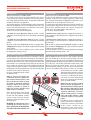
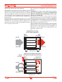
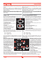
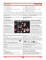
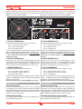
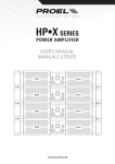
english
italiano
USER’S MANUAL y MANUALE D’USO
w w w. p ro e l g ro u p. co m
SAFETY AND PRECAUTIONS
AVVERTENZE PER LA SICUREZZA
FCC COMPLIANCE NOTICE
This device complies with part 15 of the FCC rules. Operation is subject to the following two conditions:
(1) This device may not cause harmful interference, and
(2) this device must accept any interference received, including interference that may cause undesired
operation.
CAUTION: Changes or modifications not expressly approved by the party responsible for compliance could
void the user’s authority to operate the equipment.
NOTE: This equipment has been tested and found to comply with the limits for a Class B digital device, pursuant to
part 15 of the FCC Rules. These limits are designed to provide reasonable protection against harmful interference
in a residential installation. This equipment generates, uses, and can radiate radio frequency energy and, if
not installed and used in accordance with the instruction manual, may cause harmful interference to radio
communications. However, there is no guarantee that interference will not occur in a particular installation. If
this equipment does cause harmful interference to radio or television reception, which can be determined by
turning the equipment off and on, the user is encouraged to try to correct the interference by one or more of
the following measures:
• Reorient or relocate the receiving antenna.
• Increase the separation between the equipment and receiver.
• Connect the equipment into an outlet on a circuit different from that to which the receiver is connected.
• Consult the dealer or an experienced radio/TV technician for help.
ENG
2
ITA
AVVERTENZE PER LA SICUREZZA
SAFETY AND PRECAUTIONS
This marking shown on the product or its literature, indicates that it should not
be disposed with other household wastes at the end of its working life. To prevent
possible harm to the enviroment or human health from uncontrolled waste disposal,
please separate this from other types of wastes and recycle it responsibly to promote
the sustainable reuse of material resources. Household users should contact either the
retailer where they purchased this product, or their local government office, for details
of where and how they can take this item for environmentally safe recycling. Business users should
contact their supplier and check the terms and conditions of the purchase contract. This product
should not be mixed with other commercial wastes for disposal.
Il marchio riportato sul prodotto o sulla documentazione indica che il prodotto non
deve essere smaltito con altri rifiuti domestici al termine del ciclo di vita. Per evitare
eventuali danni all’ambiente si invita l’utente a separare questo prodotto da altri tipi
di rifiuti e di riciclarlo in maniera responsabile per favorire il riutilizzo sostenibile delle
risorse materiali. Gli utenti domestici sono invitati a contattare il rivenditore presso il
quale è stato acquistato il prodotto o l’ufficio locale preposto per tutte le informazioni
relative alla raccolta differenziata e al riciclaggio per questo tipo di prodotto. Gli utenti aziendali sono
invitati a contattare il proprio fornitore e verificare i termini e le condizioni del contratto di acquisto.
Questo prodotto non deve essere smaltito unitamente ad altri rifiuti commerciali.
The lightning flash with arrowhead symbol within an equilateral triangle is intended
to alert the user to the presence of uninsulated “dangerous voltage” within the
product’s enclosure, that may be of sufficient magnitude to constitute a risk of
electric shock to persons.
Il simbolo del lampo con freccia in un triangolo equilatero intende avvertire
l'utilizzatore per la presenza di "tensioni pericolose" non isolate all'interno
dell'involucro del prodotto, che possono avere una intensità sufficiente a costituire
rischio di scossa elettrica alle persone.
The exclamation point within an equilateral triangle is intended to alert the user to
the presence of important operating and maintenance (servicing) instructions in the
literature accompanying the appliance.
Il punto esclamativo in un triangolo equilatero intende avvertire l'utilizzatore
per la presenza di importanti istruzioni per l'utilizzo e la manutenzione nella
documentazione che accompagna il prodotto.
SAFETY AND PRECAUTIONS
AVVERTENZE PER LA SICUREZZA
• ATTENZIONE - Durante le fasi di uso o manutenzione, devono essere prese alcune precauzioni
onde evitare danneggiamenti alle strutture meccaniche ed elettroniche del prodotto.
Prima di utilizzare il prodotto, si prega di leggere attentamente le seguenti istruzioni per la
sicurezza. Prendere visione del manuale d’uso e conservarlo per successive consultazioni:
– In presenza di bambini, controllare che il prodotto non rappresenti un pericolo.
– Posizionare l’apparecchio al riparo dagli agenti atmosferici e a distanza di sicurezza dall’acqua,
dalla pioggia e dai luoghi ad alto grado di umidità.
– Collocare o posizionare il prodotto lontano da fonti di calore quali radiatori, griglie di
riscaldamento e ogni altro dispositivo che produca calore.
– Collocare o posizionare il prodotto in modo che non ci siano ostruzioni alla sua propria ventilazione
e dissipazione di calore. Non installare in uno spazio limitato.
– Evitare che qualsiasi oggetto o sostanza liquida entri all’interno del prodotto.
– Il prodotto deve essere connesso esclusivamente alla rete elettrica delle caratteristiche descritte
nel manuale d’uso o scritte sul prodotto, usando esclusivamente il cavo rete in dotazione e
controllando sempre che sia in buono stato, in particolare la spina e il punto in cui il cavo esce dal
prodotto.
– Non annullare la sicurezza garantita dall'uso di spine polarizzate o con messa a terra.
– Fare attenzione che il punto di alimentazione della rete elettrica sia dotato di una efficiente presa
di terra.
– Disconnettere il prodotto dalla rete elettrica durante forti temporali o se non viene usato per un
lungo periodo di tempo.
– Non disporre oggetti sul cavo di alimentazione, non disporre i cavi di alimentazione e segnale
in modo che qualcuno possa incianparci. Altresì non disporre l’apparecchio sui cavi di altri apparati.
Installazioni inappropriate di questo tipo possono creare la possibilità di rischio di incendio e/o danni
alle persone.
– Questo prodotto in combinazione con altoparlanti può essere capace di produrre livelli sonori
che possono causare perdite d’udito permanenti. Si raccomanda di evitare l’esposizione ad alti livelli
sonori o livelli non confortevoli per periodi di tempo lunghi. Se si notano perdite d’udito o acufeni
(fischii) consultare un audiologo.
• CAUTION - Before using this product read carefully the following safety instructions. Take a look
of this manual entirely and preserve it for future reference.
When using any electric product, basic precautions should always be taken, including the
following:
– To reduce the risk, close supervision is necessary when the product is used near children.
– Protect the apparatus from atmospheric agents and keep it away from water, rain and high
humidity places.
– This product should be site away from heat sources such as radiators, lamps and any other device
that generate heat.
– This product should be located so that its location or position does not interfere with its proper
ventilation and heating dissipation. Do not install in a confined space.
– Care should be taken so that objects and liquids do not go inside the product.
– The product should be connected to a power supply mains line only of the type described on the
operating instructions or as marked on the product. Connect the apparatus to a power supply using
only power cord included making always sure it is in good conditions, specially the plug and the point
where it exit from the apparatus.
– Do not cancel the safety feature assured by means of a polarized line plug (one blade wider than
the other) or with a earth connection.
– Make sure that power supply mains line has a proper earth connection.
– Power supply cord should be unplugged from the outlet during strong thunderstorm or when left
unused for a long period of time.
– Do not place objects on the product’s power cord or place it in a position where anyone could
trip over, walk on or roll anything over it. Do not allow the product to rest on or to be installed over
power cords of any type. Improper installations of this type create the possibility of fire hazard and/or
personal injury.
– This product in combination with loudspeakers may be capable of producing sound levels that
could cause permanent hearing loss. Exposure to extremely high noise levels may cause permanent
hearing loss. Individuals vary considerably in susceptibility to noise-induced hearing loss, but nearly
everyone will lose some hearing if exposed to sufficiently intense noise for a period of time. The U.S.
Government’s Occupational Safety and Health Administration (OSHA) has specified the permissible
noise level exposures shown in the following chart. According to OSHA, any exposure in excess of
these permissible limits could result in some hearing loss. To ensure against potentially dangerous
exposure to high sound pressure levels, it is recommended that all persons exposed to equipment
capable of producing high sound pressure levels use hearing protectors while the equipment is in
operation. Ear plugs or protectors in the ear canals or over the ears must be worn when operating
the equipment in order to prevent permanent hearing loss if exposure is in excess of the limits set
forth here.
Duration Per Day
In Hours
Sound Level dBA
Slow Response
Typical
Example
8
90
Duo in small club
6
92
4
95
3
97
2
100
1.5
102
1
105
0.5
110
0.25 or less
115
IN CASO DI GUASTO
• In caso di guasto o manutenzione questo prodotto deve essere ispezionato da personale
qualificato quando:
– Ci sono difetti sulle connessioni o sui cavi di collegamento in dotazione.
– Sostanze liquide sono penetrate all’interno del prodotto.
– Il prodotto è caduto e si è danneggiato.
– Il prodotto non funziona normalmente esibendo una marcato cambio di prestazioni.
– Il prodotto perde sostanze liquide o gassose o ha l’involucro danneggiato.
• Non intervenire sul prodotto.
• Rivolgersi a un centro di assistenza autorizzato Proel.
CONFORMITÀ CE
Subway Train
• I Prodotti Proel sono conformi alla direttiva 89/336/EEC (EMC) e successive modifiche 92/31/EEC
e 93/68/EEC, secondo gli standard EN 55103-1 ed EN 55103-2 ed alla direttiva 73/23/EEC (LVD) e
successive modifiche 93/68/EEC, secondo lo standard EN 60065.
Very loud classical music
IMBALLAGGIO, TRASPORTO E RECLAMI
Traffic noise
• L’imballo è stato sottoposto a test di integrità secondo la procedura ISTA 1A. Si raccomanda di
controllare il prodotto subito dopo l’apertura dell’imballo.
• Se vengono riscontrati danni informare immediatamente il rivenditore. Conservare quindi
l’imballo completo per permetterne l’ispezione.
• Proel declina ogni responsabilità per danni causati dal trasporto.
• Le merci sono vendute “franco nostra sede” e viaggiano sempre a rischio e pericolo del
distributore.
• Eventuali avarie e danni dovranno essere contestati al vettore. Ogni reclamo per imballi
manomessi dovrà essere inoltrato entro 8 giorni dal ricevimento della merce.
Loudest parts at a rock concert
IN CASE OF FAULT
• In case of fault or maintenance this product should be inspected only by qualified service
personnel when:
– There is a flaw either in the connections or in the supplied connecting cables.
ENG
3
ITA
SAFETY AND PRECAUTIONS
AVVERTENZE PER LA SICUREZZA
– Liquids have spilled inside the product.
– The product has fallen and been damaged.
– The product does not appear to operate normally or exhibits a marked change in performance.
– The product has been losted liquids or gases or the enclosure is damaged.
• Do not operate on the product, it has no user-serviceable parts inside.
• Refer servicing to an authorized maintenance centre.
GARANZIE E RESI
• I Prodotti Proel sono provvisti della garanzia di funzionamento e di conformità alle proprie
specifiche, come dichiarate dal costruttore.
• La garanzia di funzionamento è di 24 mesi dopo la data di acquisto. I difetti rilevati entro il
periodo di garanzia sui prodotti venduti, attribuibili a materiali difettosi o difetti di costruzione,
devono essere tempestivamente segnalati al proprio rivenditore o distributore, allegando evidenza
scritta della data di acquisto e descrizione del tipo di difetto riscontrato. Sono esclusi dalla garanzia
difetti causati da uso improprio o manomissione. Proel SpA constata tramite verifica sui resi la
difettosità dichiarata, correlata all’appropriato utilizzo, e l’effettiva validità della garanzia; provvede
quindi alla sostituzione o riparazione dei prodotti, declinando tuttavia ogni obbligo di risarcimento
per danni diretti o indiretti eventualmente derivanti dalla difettosità.
CE CONFORMITY
• Proel products comply with directive 89/336/EEC (EMC) and following modifications 92/31/EEC
and 93/68/EEC, as stated in EN 55103-1 and EN 55103-2 standards and with directive 73/23/EEC
(LVD) and following modifications 93/68/EEC, as stated in EN 60065 standard.
PACKAGING, SHIPPING AND COMPLAINT
INSTALLAZIONE E LIMITAZIONI D’USO
• This unit package has been submitted to ISTA 1A integrity tests. We suggest you control the unit
conditions immediately after unpacking it.
• If any damage is found, immediately advise the dealer. Keep all unit packaging parts to allow
inspection.
• Proel is not responsible for any damage that occurs during shipment.
• Products are sold “delivered ex warehouse” and shipment is at charge and risk of the buyer.
• Possible damages to unit should be immediately notified to forwarder. Each complaint for
manumitted package should be done within eight days from product receipt.
• I Prodotti Proel sono destinati esclusivamente ad un utilizzo specifico di tipo sonoro: segnali di
ingresso di tipo audio (20Hz-20kHz). Proel declina ogni responsabilità per danni a terzi causati da
mancata manutenzione, manomissioni, uso improprio o installazione non eseguita secondo le norme
di sicurezza.
• L'installazione di questi amplificatori è prevista su rack 19" ventilati per prodotti ad uso
professionale. Questi amplificatori prevedono fori di ventilazione sul frontale e sul retro del prodotto.
Evitare assolutamente di ostruire la ventilazione fronte-retro dell'apparecchio onde prevenire alte
temperature al suo interno, che potrebbero provocare guasti pericolosi e incendio.
• Non installare apparecchi con un alta sensibilità e un alto guadagno quali mixer, preamplificatori,
registratori, unità di conversione AD/DA etc. direttamente sopra o sotto questi amplificatori. Siccome
questi amplificatori hanno una notevole potenza generano un forte campo elettromagnetico che
può causare disturbi in apparecchi privi di un adeguata schermatura nelle proprie vicinanze. Se un
amplificatore ed uno uno di questi apparecchi sensibili è installato nello stesso rack si raccomanda
di installare l'amplificatore nella posizione più bassa e l'apparecchio sensibile nella posizione più
alta.
• Installare questi amplificatori il più lontano possibile da radioricevitori e televisori. Un
amplificatore installato in prossimità di questi apparati può causare interferenza e rumore con
conseguente degrado della ricezione di immagini e suoni.
• La Proel S.p.a. si riserva di modificare il prodotto e le sue specifiche senza preavviso.
• Proel declina ogni responsabilità per danni a terzi causati da mancata manutenzione,
manomissioni, uso improprio o installazione non eseguita secondo le norme di sicurezza e a regola
d'arte.
WARRANTY AND PRODUCTS RETURN
• Proel products have operating warranty and comply their specifications, as stated by
manufacturer.
• Proel warrants all materials, workmanship and proper operation of this product for a period of two
years from the original date of purchase. If any defects are found in the materials or workmanship
or if the product fails to function properly during the applicable warranty period, the owner should
inform about these defects the dealer or the distributor, providing receipt or invoice of date of
purchase and defect detailed description. This warranty does not extend to damage resulting from
improper installation, misuse, neglect or abuse. Proel S.p.A. will verify damage on returned units,
and when the unit has been properly used and warranty is still valid, then the unit will be replaced
or repaired. Proel S.p.A. is not responsible for any "direct damage" or "indirect damage" caused by
product defectiveness.
INSTALLATION AND DISCLAIMER
ALIMENTAZIONE E MANUTENZIONE
• Proel products have been expressly designed for audio application, with signals in audio
range (20Hz to 20kHz). Proel has no liability for damages caused in case of lack of maintenance,
modifications, improper use or improper installation non-applying safety instructions.
• These amplifiers are adapted in a properly ventilated, standard professional 19" rack. These units
feature ventilation holes on the front and back panels. Absolutely do not obstruct the ventilation
holes. Blocked ventilation can cause damages and fire.
• Do not locate sensitive high-gain equipment such as mixer, preamplifiers, recorders or AD/DA
conversion units directly above or below these amplifiers. Because these amplifiers have a high
power density, it ha a strong magnetic field which can induce hum into unshielded devices that are
located nearby. If an equipment rack is used, we recommend locating the amplifier in the bottom of
the rack and the mixer, preamplifier or other sensitive equipment at the top.
• Proel S.p.A. reserves the right to change these specifications at any time without notice.
• Proel S.p.A. declines any liability for damages to objects or persons caused by lacks of
maintenance, improper use, installation not performed with safety precautions and at the state of
the art.
• Pulire il prodotto unicamente con un panno asciutto.
• Controllare periodicamente che le aperture di raffredamento non siano ostruite da accumuli di
polvere, provvedere alla rimozione della polvere mediante un pennello o aria compressa.
• Gli amplificatori HPA450, HPA750 e HPD1000, HPD1500, HPD2000, HPD3000 della Proel sono
costruiti in CLASSE I e prevedono sempre il collegamento mediante presa di corrente con terminale
di terra di protezione (terzo terminale di terra).
• Prima di collegare l'apparecchio alla presa di corrente, accertatevi che la tensione di rete corrisponda
a quella indicata sul retro dell’apparato, è consentito un margine del ±10% rispetto al valore
nominale.
• Per scollegare completamente questi apparecchi dalla rete estrarre la spina di alimentazione dalla
presa di corrente.
• LA SOSTITUZIONE DI FUSIBILI ALL'INTERNO DELL'APPARATO È CONSENTITO
ESCLUSIVAMENTE A PERSONALE QUALIFICATO.
• CONTROLLARE LO STATO DEI FUSIBILI DI PROTEZIONE ESCLUSIVAMENTE AD
APPARATO SPENTO E DISCONNESSO DALLA RETE ELETTRICA.
• RIMPIAZZARE IL FUSIBILE DI PROTEZIONE ESCLUSIVAMENTE CON UN FUSIBILE CON
LE MEDESIME CARATTERISTICHE RIPORTATE SUL PRODOTTO.
• SE DOPO LA SOSTITUZIONE, IL FUSIBILE INTERROMPE NUOVAMENTE IL
FUNZIONAMENTO DELL'APPARATO, NON INSISTERE E CONTATTARE IL SERVIZIO
ASSISTENZA PROEL.
POWER SUPPLY AND MAINTENANCE
• Clean only with dry cloth.
• Check periodically that the slots for its proper ventilation and heating dissipation are not
obstructed by dust, remove the dust using a dry brush or a compressed air gun.
• The HPA450, HPA750 e HPD1000, HPD1500, HPD2000, HPD3000 amplifiers of Proel have been
designed with CLASS I construction and must be connected always to a mains socket outlet with a
proctetive earth connection (the third grounding prong).
• Before connecting the product to the mains outlet make certain that the mains line voltage
matches that shown on the rear of the product, a tolerance of up to ±10% is acceptable.
• To disconnect these equipment from the AC Mains, disconnect the power supply cord plug from the
AC receptacle.
• THE REPLACEMENT OF FUSES INSIDE THE APPARATUS MUST BE MADE ONLY BY
QUALIFIED PERSONNEL.
• CHECK THE CONDITION OF THE PROTECTION FUSE, ACCESSIBLE OUTWARD, ONLY
WITH THE APPARATUS SWITCHED OFF AND DISCONNECTED FROM THE MAINS LINE
OUTLET.
• REPLACE THE PROTECTION FUSE ONLY WITH SAME TYPE AS SHOWN ON THE
PRODUCT.
• IF AFTER THE SUBSTITUTION, THE FUSE INTERRUPTS AGAIN THE APPARATUS
WORKING, DO NOT TRY AGAIN THEN CONTACT THE PROEL SERVICE CENTER.
ENG
4
ITA
CONTENTS
INDICE
CONTENTS
INDICE
SAFETY AND PRECAUTIONS . . . . . . . . . . . . . . . . . . . . . . . . . . . . . . . . . .3
IN CASE OF FAULT . . . . . . . . . . . . . . . . . . . . . . . . . . . . . . . . . . . . . . . . . .3
CE CONFORMITY . . . . . . . . . . . . . . . . . . . . . . . . . . . . . . . . . . . . . . . . . . .4
PACKAGING, SHIPPING AND COMPLAINT . . . . . . . . . . . . . . . . . . . . . . .4
WARRANTY AND PRODUCTS RETURN . . . . . . . . . . . . . . . . . . . . . . . . . .4
INSTALLATION AND DISCLAIMER. . . . . . . . . . . . . . . . . . . . . . . . . . . . . .4
POWER SUPPLY AND MAINTENANCE . . . . . . . . . . . . . . . . . . . . . . . . . .4
INTRODUCTION . . . . . . . . . . . . . . . . . . . . . . . . . . . . . . . . . . . . . . . . . . . .6
SETUP AND RACK MOUNTING . . . . . . . . . . . . . . . . . . . . . . . . . . . . . . . .6
FRONT PANEL . . . . . . . . . . . . . . . . . . . . . . . . . . . . . . . . . . . . . . . . . . . . .8
REAR PANEL . . . . . . . . . . . . . . . . . . . . . . . . . . . . . . . . . . . . . . . . . . . . . .9
ADVANCED FEATURES . . . . . . . . . . . . . . . . . . . . . . . . . . . . . . . . . . . . 11
CONNECTIONS. . . . . . . . . . . . . . . . . . . . . . . . . . . . . . . . . . . . . . . . . . . 12
CONNECTION EXAMPLES . . . . . . . . . . . . . . . . . . . . . . . . . . . . . . . . . . 13
TROUBLESHOOTING . . . . . . . . . . . . . . . . . . . . . . . . . . . . . . . . . . . . . . 14
HP•A450 TECHNICAL SPECIFICATIONS . . . . . . . . . . . . . . . . . . . . . . 15
HP•A750 TECHNICAL SPECIFICATIONS . . . . . . . . . . . . . . . . . . . . . . 16
AVVERTENZE PER LA SICUREZZA . . . . . . . . . . . . . . . . . . . . . . . . . . . . . .3
IN CASO DI GUASTO . . . . . . . . . . . . . . . . . . . . . . . . . . . . . . . . . . . . . . . .3
CONFORMITÀ CE . . . . . . . . . . . . . . . . . . . . . . . . . . . . . . . . . . . . . . . . . . .3
IMBALLAGGIO, TRASPORTO E RECLAMI . . . . . . . . . . . . . . . . . . . . . . . .3
GARANZIE E RESI . . . . . . . . . . . . . . . . . . . . . . . . . . . . . . . . . . . . . . . . . .4
INSTALLAZIONE E LIMITAZIONI D’USO . . . . . . . . . . . . . . . . . . . . . . . . .4
ALIMENTAZIONE E MANUTENZIONE . . . . . . . . . . . . . . . . . . . . . . . . . . .4
INTRODUZIONE . . . . . . . . . . . . . . . . . . . . . . . . . . . . . . . . . . . . . . . . . . . .6
INSTALLAZIONE E MONTAGGIO A RACK . . . . . . . . . . . . . . . . . . . . . . . .6
PANNELLO FRONTALE . . . . . . . . . . . . . . . . . . . . . . . . . . . . . . . . . . . . . . .8
PANNELLO POSTERIORE . . . . . . . . . . . . . . . . . . . . . . . . . . . . . . . . . . . . .9
FUNZIONI AVANZATE . . . . . . . . . . . . . . . . . . . . . . . . . . . . . . . . . . . . . 11
CONNESSIONI . . . . . . . . . . . . . . . . . . . . . . . . . . . . . . . . . . . . . . . . . . . 12
ESEMPI DI CONNESSIONE . . . . . . . . . . . . . . . . . . . . . . . . . . . . . . . . . . 13
PROBLEMATICE COMUNI . . . . . . . . . . . . . . . . . . . . . . . . . . . . . . . . . . 14
HP•A450 SPECIFICHE TECNICHE. . . . . . . . . . . . . . . . . . . . . . . . . . . . 15
HP•A750 SPECIFICHE TECNICHE. . . . . . . . . . . . . . . . . . . . . . . . . . . . 16
ENG
5
ITA
SETUP & RACK MOUNTING
INSTALLAZIONE E MONTAGGIO A RACK
INTRODUCTION
INTRODUZIONE
Thank you for having chosen a PROEL amplifier.
The new HP-A series of professional power amplifiers is the result of
a deep and meticulous stylistic and functional research merged into a
series of high quality and reliable products, essential devices both in fixed
installations and “on the road” applications.
The powerful performances of the HP-A amplifiers satisfy an exceptionally
wide range of amplification needs: live touring gigs, dance floors, sport
venues, opera and drama theathres, worship venues, theme parks,
cinema theathres, television studio and so on.
The HP-A series consists of the following models:
• HP-A450 with two indipendent channels, parallel or bridge
configurable, made with bipolar devices in class-B shape with floating
ground.
• HP-A750 with two indipendent channels, parallel or bridge
configurable, made with bipolar devices in class-B shape with floating
ground.
All models are fitted in 2 standard rack unit and are equipped with a
Soft Clipping limiter that gives an undistorted output signal in any input
signal condition.
To make the best use of these amplifiers, please read the manual
thoroughly before operating. Let's go!
Grazie per aver scelto un amplificatore PROEL.
La nuova linea di amplificatori di potenza professionali HP è frutto di
un’intensa e meticolosa ricerca stilistica e funzionale confluita in una
serie di prodotti di alta qualità ed affidabilità, fondamentali sia per le
installazioni fisse che per le applicazioni “on the road”.
Le prestazioni dei nuovi finali di potenza HP sono tali da soddisfare una
vastissima gamma di applicazioni del settore professionale: concerti in
tour, discoteche, palazzetti, teatri di opera e di prosa, luoghi di culto,
parchi a tema, sale cinematografiche, studi televisivi, etc.
La serie HP è costituita dai modelli:
• HP-A450 con due canali indipendenti, configurabili in parallelo o a
ponte, realizzati con dispositivi bipolari in configurazione classe-B con
massa flottante.
• HP-A750 con due canali indipendenti, configurabili in parallelo o a
ponte, realizzati con dispositivi bipolari in configurazione classe-B con
massa flottante.
Tutti i modelli sono di dimensioni di 2 unità rack standard e sono dotati
di circuiti di limiter Soft Clipping per un segnale non distorto in qualsiasi
condizione del segnale di ingresso.
Per una installazione ed un uso corretto degli amplificatori HP, leggete
attentamente tutto il manuale. Pronti ... Via!
SETUP AND RACK MOUNTING
INSTALLAZIONE E MONTAGGIO A RACK
All HP-A amplifiers will mount in two units of a standard 19" (48.3cm)
rack, the front panel is provided of four mounting holes. HP-A amplifiers
uses a forced-air cooling system to mantain a low operating temperature.
Drawn by an internal fan, cold air enters through the slots in the front
panel and flows over and through internal components, then the hot
air gets out from the rear panel slots. The HP-A amplifiers drive the fan
using a variable-speed DC circuit, which is controlled by sensing the heat
sink temperature. The fan speed will increase only when the temperature
of either heat sink requires it, which keeps
fan noise to a minimum and helps cut dust
accumulation inside.
NOTE: In order to prevent the dust
accumulation inside the amplifier, the
two air vents on front panel have a dust
filter. Each time these filters are dirty
(it depends on enviroment conditions)
you have to remove the air slots using
a phillips screwdriver (as shown on
figure) and clean the dust filter using
compressed air or a soft brush.
Under extreme thermal load, the fan will
force a very large volume of air through
the heat sinks. If the amplifier overheats,
another sensing circuit shuts down the
amplifier to cut off power until it cools to a
safe temperature.
IMPORTANT: The exhaust hot air is forced
out through the rear of the chassis (see
figure). ABSOLUTELY DO NOT OBSTRUCT
THE FRONT AND REAR OPENINGS and
Tutti gli amplificatori HP-A è previsto che siano montati su due unità
di un rack standard da 19" (48.3cm), il pannello frontale è provvisto
di quattro fori per il fissaggio al rack. Gli amplificatori HP-A usano un
sistema di raffredamento ad aria forzata per mantenere una temperatura
di esercizio bassa. L'aria fredda, aspirata dalla ventola interna, entra
attraverso le fessure sul pannello frontale e scorre sui componenti
interni raffredandoli, quindi l'aria calda esce dalle fessure del pannello
posteriore. Gli amplificatori HP-A pilotano la ventola con un circuito a
velocità variabile il cui controllo è sensibile
alla temperatura del dissipatore. La velocità
della ventola aumenterà solo di quanto è
necessario per il raffredamento interno:
in tal modo sia il rumore introdotto dalla
ventola che l'accumulo di polvere all'interno
saranno contenuti al minimo.
NOTA: Al fine di prevenire l'accumulo
di polvere interno all'amplificatore, le
aperture frontali per l'aria dispongono di
filtri anti-polvere. Ogni volta che questi
filtri sono sporchi (questo dipende dalle
condizioni ambientali) si dovranno
rimuovere i filtri usando un cacciavite a
stella (come visibile in figura) e pulirli
usando aria compressa o una spazzola
leggera.
In condizioni estreme, la ventola forzerà
un flusso d'aria notevole sui dissipatori. Se
l'amplificatore continuerà a surriscaldarsi
un'altro circuito, sensibile ad una
temperatura più alta del dissipatore,
silenzierà temporaneamente le uscite,
ENG
6
ITA
SETUP & RACK MOUNTING
INSTALLAZIONE E MONTAGGIO A RACK
always let them free from cables or other materials.
If the amplifier is rack mounted, make sure the exhaust air can flow
without resistance from front to back side of the rack. Therefore we
suggest to use only rack stands with front and back cover completely
removed (Proel KR10AD as example for fixed installation or Proel CR
series for touring use). In this case amplifiers may be stacked directly on
top of each other (no space needed between units), starting from the
bottom of the rack.
We advice against the use of rack with closed backs (or close to a back
wall), but if you can do otherwise, we suggest to leave at least one
standard rack space of opening between every two amplifiers and to
make sure there is enough space at the rear of the amplifiers to allow the
air to escape (at least 15 cm or 6 inch).
fino al momento in cui l'amplificatore tornerà alla sua temperatura
operativa.
IMPORTANTE: L'aria calda esausta è forzata ad uscire sul lato
posteriore dell'amplificatore (vedi figura). ASSOLUTAMENTE NON
OSTRUIRE LE APERTURE FRONTALI E POSTERIORI, lasciandole sempre
libere da cavi o altri materiali.
Se montato a rack, assicurarsi che l'aria possa fluire senza alcuna
resistenza dal fronte al retro, per cui viene suggerito l'uso di supporti
rack senza coperchi frontali e posteriori (per esempio i Proel KR10AD per
le installazioni fisse o i Proel serie CR per l'uso in tour): in questo caso
gli amplificatori possono essere impilati direttamente l'uno sopra l'altro
senza spazi liberi, partendo dal basso del rack.
Viene sconsigliato l'uso di rack con il retro chiuso o a ridosso di un muro
posteriore, ma se non è possibile fare altrimenti, viene suggerito di
lasciare almeno una unità rack aperta fra ogni due amplificatori e di
assicurarsi che ci sia spazio sufficiente sul retro degli amplificatori per cui
l'aria fuoriesca (almeno 15 cm).
RECOMMENDED INSTALLATION
INSTALLAZIONE RACCOMANDATA
FRONT
FRONTALE
REAR
POSTERIORE
COLD AIR
HOT AIR
ARIA FREDDA
ARIA CALDA
8U OPEN RACK
RACK aperto 8U
HOT AIR
ARIA CALDA
EVENTUAL INSTALLATION WITH CLOSED BACK
EVENTUALE INSTALLAZIONE CON RETRO CHIUSO
FRONT
FRONTALE
REAR (closed)
POSTERIORE (chiuso)
COLD AIR
ARIA FREDDA
10U closed RACK
RACK chiuso 10U
ENG
7
15 cm
6 inch
ITA
FRONT PANEL
PANNELLO FRONTALE
FRONT PANEL
1. Cooling vent
PANNELLO FRONTALE
1. Apertura per aria di raffredamento
Removable cooling vent: always keep it clean from dust.
Apertura per l'aria rimovibile: mantenerla sempre pulita dalla polvere.
2. Power switch
2. Interuttore accensione
Amplifier is "ON" when the switch is in the "I" position.
L' amplificatore è acceso "ON" quando l'interuttore è nella posizione "I".
3. Power indicator
3. Indicatore di accensione
Blue LED: when lighted indicates amplifier has been turned on and AC
power is available.
LED blu: quando acceso indica che l'amplificatore è stato acceso e
l'alimentazione AC è disponibile.
4. Level control Channel 1
4. Controllo di Livello Canale 1
Rotary detented level control: in STEREO and PARALLEL operation it
attenuates the level of the signal sent to the channel 1 of the amplifier,
while in BRIDGE operation it operates as single control to attenuate the
level of the signal sent to both the channels.
The attenuation ranges from “∞” fully closed (the signal is completely
attenuated) to “0” fully open, nominal level (the signal is not attenuated
in any way, so is fed to the amplifier channel at the same level at which
it arrives on input).
Controllo di livello rotativo a scatti: in modalità STEREO e PARALLEL
attenua il livello del segnale inviato al canale 1 dell'amplificatore, o in
modalità BRIDGE agisce come singolo controllo per attenuare il livello
del segnale inviato a entrambi i canali.
L' attenuazione varia tra completamente chiuso “∞” a completamente
aperto “0” o livello nominale (il segnale non è attenuato in nessun modo,
viene inviato al canale dell'amplificatore allo stesso livello con cui arriva
all'ingresso).
5. Level control Channel 2
5. Level control Channel 2
Rotary detented level control: in STEREO and PARALLEL operation it
attenuates the level of the signal sent to the channel 2 of the amplifier.
In BRIDGE operation it doesn't work.
The attenuation ranges from “∞” fully closed (the signal is completely
attenuated) to “0” fully open, nominal level (the signal is not attenuated
in any way, so is fed to the amplifier channel at the same level at which
it arrives on input).
Controllo di livello rotativo a scatti: in modalità STEREO e PARALLEL
attenua il livello del segnale inviato al canale 2 dell'amplificatore, in
modalità BRIDGE non ha alcun effetto.
L' attenuazione varia tra completamente chiuso “∞” a completamente
aperto “0” o livello nominale (il segnale non è attenuato in nessun modo,
viene inviato al canale dell'amplificatore allo stesso livello con cui arriva
all'ingresso).
6. Channel 1 Signal indicator
6. Indicatore di segnale del Canale 1
Green LED illuminates to indicate the presence of the signal at the
amplifier channel 1 input. The indication is after the level control.
LED verde che si accende per indicare la presenza del segnale all'ingresso
del canale 1. L'indicazione è dopo il controllo di livello.
7. Channel 2 Signal indicator
7. Indicatore di segnale del Canale 2
Green LED illuminates to indicate the presence of the signal at the
amplifier channel 2 input. The indication is after the level control.
LED verde che si accende per indicare la presenza del segnale all'ingresso
del canale 2. L'indicazione è dopo il controllo di livello.
8. Channel 1 Clip/Limit indicator
8. Indicatore di Clip/Limit del Canale 1
Red LED illuminates when the channel's output is distorted (Clip) or
limited (Limit). When this LED flashes reduce the input signal level of
channel 1.
LED rosso che si accende quando l'uscita del canale è distorta (Clip) o
limitata (Limit). Quando questo LED lampeggia ridurre il segnale di
ingresso del canale 1.
9. Channel 2 Clip/Limit indicator
9. Indicatore di Clip/Limit del Canale 2
Red LED illuminates when the channel's output is distorted (Clip) or
LED rosso che si accende quando l'uscita del canale è distorta (Clip) o
ENG
8
ITA
REAR PANEL
PANNELLO POSTERIORE
limited (Limit). When this LED flashes reduce the input signal level of
channel 2.
NOTE: When the amplifier operates in BRIDGE mode both LED
indicators illuminate simultaneously, esclusively depending on
channel 1 input signal.
NOTE: When a short circuit protection trips the SIGNAL LED is off and
the CLIP/LIMIT LED is permanently on, until the output short circuit
will be removed.
limitata (Limit). Quando questo LED lampeggia ridurre il segnale di
ingresso del canale 2.
NOTA: Quando l'amplificatore è in modalità BRIDGE entrambi
gli indicatori LED si accendono simultaneamente, dipendendo
esclusivamente dal segnale sul canale 1.
NOTA: Quando scatta la protezione da corto circuito il SIGNAL LED è
spento e il CLIP/LIMIT LED è sempre acceso, fino al momento in cui il
corto circuito in uscita sarà rimosso.
REAR PANEL
10. MAINS ~ inlet
PANNELLO POSTERIORE
10. Ingresso ALIMENTAZIONE RETE ELETTRICA~
Here’s where you plug in your amplifier’s mains supply cord. Connect
the power cord to an electrical outlet complying
with the power supply specifications indicated
on the apparatus. You should always use the
mains cord supplied with the amplifier. Be sure
your amplifier is turned off before you plug the
mains supply cord into an electrical outlet.
Inserire il cavo di alimentazione della rete in dotazione in questa presa.
Collegare l'altro capo del cavo di alimentazione ad una presa
di rete elettrica conforme con le specifiche di alimentazione
riportate sull'apparato. Usare eclusivamente il cavo in dotazione
all'amplificatore. Assicurarsi che l'amplificatore sia spento
prima di inserire la spina del cavo nella presa di rete.
11. Etichetta Specifiche
11. Specification Label
Un'etichetta adesiva applicata in questo punto fornisce le
seguenti indicazioni:
(1) Codice Modello
(2) Numero Seriale dell'apparecchio
(3) Tensione di alimentazione AC rete elettrica
(4) Assorbimento massimo
An adhesive label applied here shows the
following information:
(1) Model Code
(2) Serial Numer of the apparatus
(3) Mains supply AC voltage requirements
(4) Maximum power supply absorption
12. Ingresso XLR Canale 1
12. Channel 1 XLR input
Questo è un connettore XLR femmina, in grado di accettare un
segnale linea bilanciato da praticamente tutti gli apparecchi
con un livello di uscita linea. Gli ingressi XLR sono cablati come
This is a female XLR connector, which accepts
a balanced line input from almost any type of
equipment with line level outputs. The XLR inputs are wire as follows:
Pin 1 = shield or ground
Pin 2 = + positive or "hot"
Pin 3 = - negative or "cold"
This is the input of Channel 1 amplifier in STEREO mode, or the input of
both channel amplifiers 1 and 2 in PARALLEL mode, or the only input in
BRIDGE mode.
NOTE: Whenever possible, use always
balanced cables. Unbalanced lines
may also be used but may result in
noise over long cable runs. In any
case, avoid using a balanced cable
for one channel and an unbalanced
one for the other, or a balanced cable
for input (XLR) and an unbalanced
for link (JACK), as this would cause
a considerable difference in channel
levels and/or noise.
segue:
Pin 1 = schermo o massa
Pin 2 = + positivo o "caldo"
Pin 3 = - negativo o "freddo"
Questo è l'ingresso del canale 1 in modalità STEREO, o l'ingresso di
entrambe i canali 1 e 2 in modalità PARALLEL, o il solo ed unico ingresso
in modalità BRIDGE.
NOTA: Qualora possibile, usare sempre
cavi bilanciati. Cavi sbilanciati possono
essere ugualmente usati ma potrebbero
dare problemi di rumore se molto lunghi.
In ogni caso, evitate di usare un cavo
bilanciato per un canale e uno sbilanciato
per l’altro, o un cavo bilanciato per
l'ingresso (XLR) e uno sbilanciato per un
rilancio "LINK" (JACK), poiché otterreste
una sensibile differenza di livello tra un
canale e l’altro.
13. Channel 2 XLR input
13. Ingresso XLR Canale 2
This is the input of Channel 2 amplifier:
it operates only in STEREO mode.
Questo è l'ingresso del canale 2: è attivo solo
in modalità STEREO.
14. Channel 1 JACK input
14. Ingresso JACK Canale 1
This is a ¼” (6.3mm) jack connector for
Channel 1 input, which accepts a balanced or unbalanced line level input
signal from almost any type of equipment with high level outputs. When
connecting a balanced signal, wire them as follows:
ENG
È un connettore femmina da ¼” (6.3mm) tipo
jack per l'ingresso del canale 1, in grado di accettare un segnale a livello
linea bilanciato o sbilanciato da ogni tipo di sorgente.
Collegando un segnale bilanciato, le terminazioni sono le seguenti:
9
ITA
REAR PANEL
PANNELLO POSTERIORE
Tip = + positive or "hot"
Ring = - negative or "cold"
Sleeve = shield or ground
When connecting an unbalanced signal, wire them as follows:
Tip = + positive or "hot"
Sleeve = shield or ground
This connector is connected in parallel with the respective XLR-F
connector of Channel 1: this enables a second unit (e.g. another
amplifier) to be daisy-chained to the first. It’s thus possible to power
several amplifiers using the same signal, forming more powerful sound
reinforcement systems.
Tip (punta) = + positivo o "caldo"
Ring (anello) = - negativo o "freddo"
Sleeve (manicotto) = schermo o massa
Collegando un segnale sbilanciato, le terminazioni sono le seguenti:
Tip (punta) = + positivo o "caldo"
Sleeve (manicotto) = schermo o massa
Questo connettore è connesso in parallelo con il rispettivo connettore
XLR del canale 1, rendendo possibile il collegamento in cascata di una
seconda unità (per esempio un'altro amplificatore). In questo modo è
possibile inviare lo stesso segnale a più amplificatori, per formare un più
complesso e potente sistema di rinforzo del suono.
15. Channel 2 JACK input
15. Ingresso JACK Canale 2
This connector is connected in parallel with the respective XLR-F
connector of Channel 2.
Questo connettore è connesso in parallelo con il rispettivo connettore
XLR del canale 2.
16. LF 30 Hz FILTER switch
16. Interuttore LF 30 Hz FILTER
When activated this switch enables
a Low Frequency Filter to cut audio
signals under 30 Hz frequency: this a
useful feature to preserve your woofer
speakers life.
Quando attivato questo interuttore inserisce
un filtro dei bassi eliminando le frequenze al
di sotto dei 30 Hz. Questa è un'utile funzione
per preservare la durata degli altoparlanti
"woofer" per basse frequenze.
17. CLIP LIMITER switch
17. Interruttore CLIP LIMITER
When activated this switch enables the
clip limiters to dinamically reduce the
gain of the amplifiers when these are
driven near to clip distortion.
While some audio systems may already
contain protective limiters preceeding
the amplifier in the system, the
amplifier’s Anti-Clip Limiters generally
will not noticeably affect output
quality.
For systems without additional protection, the Anti-Clip Limiters can
enhance your system’s output quality and prevent catastrophic damage
to your speakers.
Even with the Anti-Clip Limiters, your amplifier should never be operated
at a level which causes the front-panel Clip LEDs to illuminate constantly.
While the Anti-Clip Limiters help to prevent damage due to peak signal
distortion, your speakers can still be damaged by excess of mean power
dissipation.
Quando attivato questo interruttore inserisce
un "clip limiter" per ridurre dinamicamente
il guadagno dell'amplificatore quando
questo è pilotato vicino al massimo segnale
accettabile prima della distorsione.
Seppure molti sistemi audio complessi
siano già dotati di limitatori di protezione
prima degli amplificatori, generalalmente
l'Anti-Clip Limiter dell'amplificatore non
apporta alcun effetto negativo alla qualità
del suono.
Per sistemi audio senza protezione preventiva, l'Anti-Clip Limiter migliora
la qualità del suono e previene seri danni agli altoparlanti.
Anche con il Clip Limiter attivato, l'amplificatore non deve lavorare con
livelli di segnale che causano l'accensione costante del LED rosso. Infatti
seppure l'Anti-Clip Limiter aiuti a prevenire danni causati dalla distorsione
dei picchi di segnale, gli altoparlanti possono essere ugualmente
danneggiati dalla eccessiva potenza media dissipata.
18. STEREO - PARALLEL - BRIDGE mode selector
18. STEREO - PARALLEL - BRIDGE mode selector
Allow the selection of STEREO, PARALLEL or BRIDGE mode operations.
In STEREO mode each amplifier channel runs indipendently driven by
respective input.
In PARALLEL mode both amplifier channels run toghether driven by
Channel 1 input.
In BRIDGE mode both amplifiers channel run toghether but with channel
1 in phase and channel 2 out of phase, both channels are driven by
Channel 1 input and the output must be taken from "BRIDGE" speakon
output.
Permette la selezione delle modalità STEREO, PARALLEL o BRIDGE.
In modalità STEREO ogni canale dell'amplificatore è indipendente
dall'altro e pilotato dal rispettivo ingresso.
In modalità PARALLEL entrambi i canali dell'amplificatore sono pilotati
insieme dall'ingresso del canale 1.
In modalità BRIDGE entrambi i canali dell'amplificatore funzionano
assieme ma con il canale 1 in fase e il canale 2 fuori fase, entrambi i canali
dell'amplificatore sono pilotati dall'ingresso del canale 1 e l'uscita deve
essere prelevata dall'uscita speakon "BRIDGE".
19. Fan cooling vent
19. Apertura per aria di raffredamento
Fan cooling vent: always keep it clear of cables or other objects.
Apertura per l'aria: mantenerla sempre sgombra da cavi e altri oggetti.
20. LINE PROTECT push button
20. Protezione dalla linea elettrica LINE PROTECT
This is the mains line circuit breaker. If it trips (entirely push out), the
Questo è la protezione per la linea elettrica. Se scatta (interamente fuori),
ENG
10
ITA
ADVANCED FEATURES
FUNZIONI AVANZATE
amplifier could be have a problem. Try to restore the normal operation
pushing the button. If it trips again don't insist and contact your nearest
PROEL service center to check the amplifier.
l'amplificatore potrebbe avere un problema. Provare a ripristinare le
normali condizioni operative premendo il bottone. Se scatta nuovamente
non insistere e contattare il più vicino centro assistenza PROEL.
21. Channel 1 SPEAKON output
21. Uscita SPEAKON Channel 1
Accept male Neutrik Speakon NL4C connector wired in this way:
• PIN 1+ connected to "in phase" output;
• PIN 1- connected to GND output;
• PIN 2+ and 2- NOT connected.
This is the amplified output of the signal applied to channel 1 input.
Connect a louspeaker with a minumum impedance of 4 ohm or more.
NOTE: Use only loudspeaker enclosure cables, never signal cables,
i.e. those normally used for microphones, instruments and audio
equipment in general.
Connettore Neutrik Speakon NL4C maschio, collegato come segue:
• PIN 1+ collegato all'uscita "in phase";
• PIN 1- collegato alla massa;
• PIN 2+ e 2- NON connessi.
Questa è l'uscita amplificata del segnale applicato all'ingresso del canale
1, collegare un altoparlante con un'impedenza minima di 4 ohm o più.
NOTA: Usare cavi specifici per altoparlanti, mai cavi di segnale,
quelli usati per microfoni, strumenti e apparecchiature audio in
generale.
22. Channel 2 SPEAKON output
22. Uscita SPEAKON Channel 2
Wired in same way as above, this is the amplified output of the signal
applied to channel 2 input if the amplifier is set in STEREO mode or the
signal applied to channel 1 input if the amplifier is set in PARALLEL mode.
Connect a louspeaker with a minumum impedance of 4 ohm or more.
Collegato come sopra, questa è l'uscita amplificata del segnale
applicato all'ingresso del canale 2, se in modalità STEREO o del segnale
applicato all'ingresso del canale 1 se in modalità PARALLEL, collegare un
altoparlante con un'impedenza minima di 4 ohm o superiore.
23. BRIDGE SPEAKON output
23. Uscita SPEAKON BRIDGE
Accept male Neutrik NL4C connector wired in this way:
• PIN 1+ connected to "in phase" (Channel 1);
• PIN 1- connected to "out phase" (Channel 2);
• PIN 2+ and 2- NOT connected.
This is the amplified output of the signal applied to channel 1 input if the
amplifier is set in BRIDGE mode. Connect a louspeaker with a minumum
impedance of 8 ohm or more.
NOTE: Use this output alone and only with BRIDGE mode setting.
Connettore Neutrik Speakon NL4C maschio, collegato come segue:
• PIN 1+ collegato all'uscita "in phase" (canale1)
• PIN 1- collegato all'uscita "out phase" (canale 2);
• PIN 2+ e 2- NON connessi.
Questa è l'uscita amplificata del segnale applicato all'ingresso del
canale 1 se l'amplificatore è impostato in modalità BRIDGE: collegare un
altoparlante con un'impedenza minima di 8 ohm o superiore.
NOTA: Usare questa uscita da sola ed unicamente in modo BRIDGE.
ADVANCED FEATURES
Short circuit protection
FUNZIONI AVANZATE
Protezione da Corto Circuito
In case of short circuit of loudspeaker cables or in case of connection
of a loudspeaker load less than the minimum specified, the amplifier
shuts down indicating on the front panel the protection status: CLIP LED
permanently on and SIGNAL LED off. Removing the fault condition the
amplifier restore its normal operation.
In caso di corto circuito dei cavi altoparlanti o in caso di connessione di un
altoparlante con carico inferiore al minimo specificato, l'amplificatore si
interrompe indicando sul panello frontale lo stato di protezione: CLIP LED
permanentemente acceso e SIGNAL LED spento. Rimuovendo la causa del
difetto l'amplificatore ripristina le normali condizioni operative.
Loudspeaker DC protection
Protezione altoparlanti da corrente continua
In case of fault of the internal bipolar devices, the loudspeakers are
protected from DC voltage output.
In caso di guasto dei dispositivi bipolari interni, gli altoparlanti sono
protetti dalla tensione continua in uscita.
ENG
11
ITA
CONNECTIONS
CONNESSIONI
CONNECTIONS
CONNESSIONI
INPUT
Balanced male XLR
hot
tip - hot
cold
ring - cold
ground
sleeve - ground
INPUT
Jack (balanced)
INPUT (ingresso)
XLR bilanciato maschio
tip - hot
*note: connect both cold and ground
to make cable from balanced to unbalanced
cold
*nota: connettere insieme cold e ground
per cavi da bilanciato a sbilanciato
ground
INPUT
Jack (unbalanced)
INPUT (ingresso)
Jack (bilanciato)
INPUT (ingresso)
Jack (sbilanciato)
negative / black / nero
1-
20mm
0.8"
n.c. 2+
1-
2-
1+
n.c.
SPEAKER POWER OUTPUTS
Neutrik NL4 Speakon Cable Connector
8mm
0.3"
BLACK
RED
1+
positive / red / rosso
POWER OUTPUT - uscite altoparlanti
Connettore per cavo tipo Speakon Neutrik NL4
PROEL code - NL4FX
Codice PROEL - NL4FX
Loudspeaker Line Losses (maximum permissible line lengths for 0.5dB losses, voltage or spl)
4 ohm load
8 ohm load
Wire section data
PROEL recommended cables
feet
meter
feet
mm2
2 wires
75
25
150
50
4.0
12
HPC624
HPC644
HPC624FR
50
17.5
100
35
2.0
14
HPC620
HPC640
HPC520
30
10
60
20
1.5
16
HPC610
20
7.5
40
15
1.0
18
HPC605
meter
AWG
4 wires
2 wires Fire-resistant
4 wires Fire-resistant
HPC540
HPC510
this is a short extraction of the wide assortment of cables available from PROEL, please visit our website at www.proelgroup.com
Perdite di collegamento linee Altoparlanti (massima lunghezza possibile per perdite inferiori a 0.5dB, tensione o spl)
carico 4 ohm
carico 8 ohm
Sezione del Cavo
Cavi raccomandati PROEL
metri
metri
mm2
2 fili
feet
meter
AWG
4 fili
2 fili resistente al fuoco
25
75
50
150
4.0
12
HPC624
HPC644
HPC624FR
17,5
50
35
100
2.0
14
HPC620
HPC640
HPC520
10
30
20
60
1.5
16
HPC610
7,5
20
15
40
1.0
18
HPC605
4 fili resistente al fuoco
HPC540
HPC510
questo è un breve estratto del vasto assortimento di cavi disponibile da PROEL, vi preghiamo di visitare il nostro sito web all'indirizzo www.proelgroup.com
ENG
12
ITA
CONNECTION EXAMPLE
ESEMPI DI CONNESSIONE
CONNECTION EXAMPLES
ESEMPI DI CONNESSIONE
R
R
L
L
STEREO MODE
4 ohm OR 8 ohm
PASSIVE SPEAKERS
to another amplifier (RIGHT ARRAY)
R
L
L
L
4 ohm OR 8 ohm
PASSIVE SPEAKERS
(LEFT ARRAY)
PARALLEL MODE
LINK*
*NOTE: THIS LINK IS ONLY AN EXAMPLE, NORMALLY SYSTEMS WITH
SUBWOOFERS HAVE A DEDICATED FILTER AND CONNECTION.
*NOTA: QUESTO COLLEGAMENTO È SOLO UN ESEMPIO, NORMALMENTE
I SISTEMI CON SUBWOOFER HANNO UN FILTRO E UN COLLEGAMENTO
DEDICATO.
BRIDGE MODE
8 ohm
PASSIVE SUBWOOFER
(LEFT ARRAY)
ENG
13
ITA
TROUBLESHOOTING
PROBLEMATICHE COMUNI
TROUBLESHOOTING
No Power
PROBLEMATICE COMUNI
Assenza di alimentazione
• The amplifier's "POWER" switch is off.
• Make sure the mains AC outlet is live (check with a tester or a lamp).
• Make sure the mains plug is securely plugged into mains AC outlet.
• Is the LINE PROTECT circuit breaker trips (entirely push out)? the
amplifier could be have a problem. Try to restore the normal operation
pushing the button. If it trips again don't insist and contact your nearest
PROEL service center to check the amplifier.
• L'amplificatore è spento.
• Accertarsi che ci sia effettivamente tensione sulla presa di corrente
(controllare con un tester o una lampada).
• Accertarsi che la spina di rete sia saldamente inserita nella presa.
• È scattato la protezione dalla linea elettrica "LINE PROTECT"
(interamente fuori)? L'amplificatore potrebbe avere un problema: provare
a ripristinare le normali condizioni operative premendo il bottone.
Se scatta nuovamente non insistere e contattare il più vicino centro
assistenza PROEL.
No Sound
• Is the loudspeaker cable connected?
• Is the SPEAKON cable connector locked into the right channel power
output socket?
• Is the SPEAKON cable connector correctly inserted? Turn it clockwise
until it clicks.
• Is the input LEVEL control for the channel turned up?
• Is the SIGNAL LED illuminated? If not check if your signal level is too
low or check the signal cable, mixer and other equipment setting and
cabling.
Nessun Suono
• È collegato il cavo degli altoparlanti?
• È il connettore SPEAKON del cavo altoparlanti nella presa di uscita di
potenza del canale giusto?
• È il connettore SPEAKON del cavo altoparlanti correttamente inserito?
Girarlo finchè non si sente il click.
• È il controllo di livello del canale girato al massimo?
• È il LED di segnale acceso? Se no, controllate se il livello di segnale sia
troppo basso o controllate il cavo di segnale, le impostazioni e i cablaggi
di mixer o altri apparecchi collegati.
No Sound and the Amplifier gets too hot
• The amplifier temperature protections trips, re-locate the amplifier in
a more ventilated location.
Nessun suono e l'amplificatore scalda eccessivamente
No Sound and Protection trip
(CLIP LED always on, SIGNAL LED always off )
• La protezione in temperatura scatta, riposizionate l'amplificatore in
una locazione più ventilata.
• Could be a possible short circuit at the amplifier loudspeakers outputs,
the speaker’s inputs or in the cabling. Locate and remove the short
circuit.
• The impedance of the loudspeakers connected is too low. Use a
speaker with a minimum impedance of 4Ω (8Ω in the Bridge mode).
• If no load connected the protection trips the same, a DC voltage has
been detected in the amplifier’s output circuit and you have to contact
you nearest service assistance center to repair the amplifier.
Nessun suono e l'amplificatore è in protezione
(CLIP LED sempre acceso, LED segnale sempre spento)
• Potrebbe esserci un corto circuito alle uscite dell'amplificatore,
all'ingresso degli altoparlanti o nel cavo di collegamento. Localizzare e
rimuovere il corto circuito.
• L'impedenza dell'altoparlante collegato è troppo bassa, usate
un'altoparlante con una impedenza minima di 4Ω (8Ω se in Bridge).
• Se senza altoparlanti collegati la protezione scatta ugualmente, una
tensione continua è presente in uscita: contattare il più vicino centro
assistenza PROEL.
Distorted Sound
• Is the limiter enabled?
• Input signal level is too high. Turn down your amplifier level controls.
NOTE: Your amplifier should never be operated at a level which causes the
Clip LEDs to illuminate constantly.
Suono Distorto
• Il limiter è attivato?
• Il livello del segnale di ingresso è troppo alto, abbassare il livello
tramite i controlli di livello in ingresso.
NOTA: L'amplificatore non deve mai lavorare con livelli che fanno
illuminare in modo pressochè costante il LED rosso.
Different channel level
• Check if are using a balanced cable for one channel and an unbalanced
one for the other, or a balanced cable for input (XLR) and an unbalanced
for link (JACK), as this would cause a considerable difference in channel
levels.
• Be sure that your loudspeaker system is fully connected and both
loudspeakers have the same impedance.
Livello differente sui canali
• Controllare se si stanno usando cavi bilanciati su un canale e sbilanciati
sull'altro, o cavi bilanciati in ingresso (XLR) e sbilanciati per il rilancio
"link" (JACK), ciò può comportare una notevole differenza di livello sui
canali.
• Assicurarsi che gli altoparlanti siano completamente collegati e
abbiano la medesima impedenza.
Noise / Hum
• Whenever possible, preferably use only balanced cables. Unbalanced
lines may also be used but may result in noise over long cable runs.
• Sometimes it helps to plug all audio equipment into the same AC
circuit so they share a common ground.
ENG
Rumore / Ronzio
• Qualora possibile, usare preferibilmente solo cavi bilanciati. Cavi
sbilanciati possono essere usati ma risulteranno rumorosi sulle lunghe
distanze.
• Talvolta può essere di aiuto alimentare tutto l'equipaggiamento
audio collegandolo dalla stessa linea di corrente AC, in modo che tutti gli
apparati condividano la stessa presa di terra.
14
ITA
HP•A450 TECHNICAL SPECIFICATION
HP•A450 SPECIFICHE TECNICHE
HP•A450 TECHNICAL SPECIFICATIONS
Levels & Data
HP•A450 SPECIFICHE TECNICHE
Connectors
Livelli & Dati
POWER SPECIFICATIONS
Output Power
standard EIA
(1 KHz Thd < 1%)
STEREO (4 ohm load)
225 W
STEREO (8 ohm load)
105 W
BRIDGE (8 ohm load)
420 W
UNBALANCED Input*
HUM & Noise
STEREO (imp. 8 ohm) 105 W
NL4 Speakon
BRIDGE (imp. 8 ohm) 420 W
SPECIFICHE ELETTRICHE
nom. sensitivity 0 dBu (0,775 Vrms)
impedance
20 Kohm
nom. sensitivity +6 dBu (1,55 Vrms)
impedance
Amplifier GAIN
Frequency Response
STEREO (imp. 4 ohm) 225 W
Potenza di Uscita
standard EIA
(1 KHz Thd < 1%)
NL4 Speakon
ELECTRICAL SPECIFICATIONS
Input
Connettori
SPECIFICHE DI POTENZA
10 Kohm
Balanced XLR
Balanced Jack
Unbalanced XLR*
Unbalanced Jack*
31 dB
unweighted
THD + Noise
impedenza 20 Kohm
sensibilità nominale +6 dBu (1,55 Vrms)
Ingresso SBILANCIATO*
impedenza 10 Kohm
Guadagno
(+0 / -1 dB) 25 Hz ÷ 25 KHz
(-3 dB points)
sensibilità nominale 0 dBu (0,775 Vrms)
Ingresso
> 100 dB
Rumore di Fondo
< 0,1 %
THD + Rumore
GENERAL SPECIFICATIONS
XLR Sbilanciato*
Jack Sbilanciato*
31 dB
(+0 / -1 dB) 25 Hz ÷ 25 KHz
Risposta in Frequenza
5 Hz ÷ 50 KHz
XLR Bilanciato
Jack Bilanciato
(punto a -3 dB)
non pesato
5 Hz ÷ 50 KHz
> 100 dB
< 0,1 %
SPECIFICHE GENERALI
Protections
Short circuit, DC voltage, Over heating
Protezioni
Corto circuito, Tensione continua, Sovra-riscaldamento
Controls
Level, 30 Hz HP filter, Limiter, Stereo / Parallel / Bridge mode
Controlli
Livello, filtro 30 Hz HP, Limiter, modo Stereo / Parallel / Bridge
Indicators
Signal, Clip, Power
Indicazioni
Segnale, Clip, Accensione
Weight
Dimensions
(WxHxD)
12,5 Kg (27.6 lb)
Peso
48,3 x 8,88 x 44,0 cm (19 x 3.5 x 17.3 inch)
Dimensioni
POWER REQUIREMENTS
12,5 Kg (27.6 lb)
(LxAxP) 48,3 x 8,88 x 44,0 cm (19 x 3.5 x 17.3 inch)
ALIMENTAZIONE DI RETE
see label on the apparatus, available for:
Mains Supply Voltage
Europe
U.S.
vedi etichetta sull'apparato, disponibile per:
230 V AC (±10 %) 50 / 60 Hz
Tensione di rete
115 V AC (±10 %) 50 / 60 Hz
Europa 230 V AC (±10 %) 50 / 60 Hz
Stati Uniti
115 V AC (±10 %) 50 / 60 Hz
Maximum consumption
both channel driven
920 VA
Consumo Massimo
entrambi i canali
Rated consumption
at 1/8 of max power out
both channel driven
325 VA
Consumo Nominale
a 1/8 max pot. di uscita
entrambi i canali 325 VA
Stand-by consumption
no signal
20 VA
Consumo in Attesa
* To make an unbalanced connection shorts pin1 an 3 on XLR plug or sleeve and ring on Jack
plug.
** Rated consumption is measured with pink noise with a crest factor of 12 dB, this can be
considered a standard music program.
senza segnale
920 VA
20 VA
* Per fare una connessione sbilanciata cortocircuitare il pin1 e il 3 sugli spinotti XLR o il collare e
il manicotto sugli spinotti Jack.
** Il consumo nominale è misurato con un rumore rosa con un fattore di cresta di 12 dB, questo
può essere considerato come un programma standard di musica.
43,4 cm
17,0 inch
8,9 cm
3.5 inch
48,3 cm
19.0 inch
39,7 cm
15.6 inch
4,2 cm
1.65 inch
ENG
15
ITA
HP•A750 TECHNICAL SPECIFICATION
HP•A750 SPECIFICHE TECNICHE
HP•A750 TECHNICAL SPECIFICATIONS
Levels & Data
HP•A750 SPECIFICHE TECNICHE
Livelli & Dati
Connectors
SPECIFICHE DI POTENZA
POWER SPECIFICATIONS
Output Power
standard EIA
(1 KHz Thd < 1%)
STEREO (4 ohm load)
375 W
STEREO (8 ohm load)
255 W
BRIDGE (8 ohm load)
860 W
UNBALANCED Input*
NL4 Speakon
HUM & Noise
STEREO (imp. 8 ohm) 255 W
NL4 Speakon
BRIDGE (imp. 8 ohm) 860 W
SPECIFICHE ELETTRICHE
nom. sensitivity
impedance
nom. sensitivity
impedance
Amplifier GAIN
Frequency Response
STEREO (imp. 4 ohm) 375 W
Potenza di Uscita
standard EIA
(1 KHz Thd < 1%)
ELECTRICAL SPECIFICATIONS
Input
Connettori
0 dBu
20 Kohm
+6 dBu
10 Kohm
Balanced XLR
Balanced Jack
Unbalanced XLR*
Unbalanced Jack*
unweighted
sensibilità nominale +6 dBu (1,55 Vrms)
impedenza 10 Kohm
Guadagno
(+0 / -1 dB) 25 Hz ÷ 25 KHz
THD + Noise
impedenza 20 Kohm
Ingresso SBILANCIATO*
33 dB
(-3 dB points)
sensibilità nominale 0 dBu (0,775 Vrms)
Ingresso
(+0 / -1 dB) 25 Hz ÷ 25 KHz
Risposta in Frequenza
Rumore di Fondo
< 0,1 %
THD + Rumore
XLR Sbilanciato*
Jack Sbilanciato*
33 dB
(punto a -3 dB)
5 Hz ÷ 50 KHz
> 100 dB
XLR Bilanciato
Jack Bilanciato
non pesato
5 Hz ÷ 50 KHz
> 100 dB
< 0,1 %
SPECIFICHE GENERALI
GENERAL SPECIFICATIONS
Protections
Short circuit, DC voltage, Over heating
Protezioni
Corto circuito, Tensione continua, Sovra-riscaldamento
Controls
Level, 30 Hz HP filter, Limiter, Stereo / Parallel / Bridge mode
Controlli
Livello, filtro 30 Hz HP, Limiter, modo Stereo / Parallel / Bridge
Indicators
Signal, Clip, Power
Indicazioni
Segnale, Clip, Accensione
Weight
Dimensions
(WxHxD)
13,5 Kg (29.8 lb)
Peso
48,3 x 8,88 x 44,0 cm (19 x 3.5 x 17.3 inch)
Dimensioni
13,5 Kg (29.8 lb)
(LxAxP) 48,3 x 8,88 x 44,0 cm (19 x 3.5 x 17.3 inch)
ALIMENTAZIONE DI RETE
POWER REQUIREMENTS
vedi etichetta sull'apparato, disponibile per:
see label on the apparatus, available for:
Mains Supply Voltage
Maximum consumption
Europe
230 V AC (±10 %) 50 / 60 Hz
U.S.
115 V AC (±10 %) 50 / 60 Hz
both channel driven
Rated consumption**
at 1/8 of max power out
both channel driven
Stand-by consumption
no signal
Tensione di rete
Europa 230 V AC (±10 %) 50 / 60 Hz
Stati Uniti
115 V AC (±10 %) 50 / 60 Hz
1430 VA
Consumo Massimo
entrambi i canali
485 VA
Consumo Nominale
a 1/8 max pot. di uscita
entrambi i canali 485 VA
22 VA
Consumo in Attesa
senza segnale
1430 VA
22 VA
* Per fare una connessione sbilanciata cortocircuitare il pin1 e il 3 sugli spinotti XLR o il collare e
il manicotto sugli spinotti Jack.
** Il consumo nominale è misurato con un rumore rosa con un fattore di cresta di 12 dB, questo
può essere considerato come un programma standard di musica.
* To make an unbalanced connection shorts pin1 an 3 on XLR plug or sleeve and ring on Jack
plug.
** Rated consumption is measured with pink noise with a crest factor of 12 dB, this can be
considered a standard music program.
43,4 cm
17,0 inch
8,9 cm
3.5 inch
48,3 cm
19.0 inch
39,7 cm
15.6 inch
4,2 cm
1.65 inch
ENG
16
ITA
FOTOCOPIATE QUESTA PAGINA. COMPILATE E RISPEDITE IN BUSTA CHIUSA IL COUPON SOTTO RIPORTATO A:
PROEL S.P.A. - Via alla Ruenia, 37/43 - 64027 Sant’Omero (Te) - Italy
OPPURE VIA FAX AL NUMERO: +39 0861 88 78 62
O VIA E-MAIL: [email protected]
Cognome ___________________________________________________________________ Nome _________________________-________________________________
Ditta/Ente______________________________________________________________________________________________________________________________
___
Indirizzo _______________________________________________________________________________________________________________________________
___
CAP______________ Città ___________________________________________________________________________________ Prov. ____________________________
___
Tel. _________________________________ Fax. __________________________________ E-mail _______________________________________________________
Prodotto _________________________________________________________________________________________________________________________________
Nome rivenditore _______________________________________________________________________________ Data acquisto ___________________________________
Si, inseritemi nel vostro database per:
Poter ricevere depliants dei nuovi prodotti
Ricevere l’invito per le demo e la presentazione in anteprima dei nuovi prodotti
Per consenso espresso al trattamento dei dati personali a fini statistici e promozionali della vostra società, presa visione dei diritti di cui all’articolo 13 legge 675/1996.
Data ______________________________________________ Firma _________________________________________________________________________________
PHOTOCOPY THIS PAGE, COMPILE AND SEND IN A SEALED ENVELOP TO:
PROEL S.P.A. - Via alla Ruenia, 37/43 - 64027 Sant’Omero (Te) - Italy
OTHERWISE FAX TO: +39 0861 88 78 62
OR BY E-MAIL: [email protected]
Name ______________________________________________________________________ Surname _________________________-_____________________________
Company / Board_______________________________________________________________________________________________________________________
______
Address _______________________________________________________________________________________________________________________________
______
POST Code______________ Town _________________________________________________Province / State / Country _________________________________________
______
Phone _________________________ Fax. _________________________________________ E-mail ____________________________________________________
______
Product _______________________________________________________________________________________________________________________________
______
Dealer ______________________________________________________________________________________ Date of purchase _____________________________
______
Yes, put my details in your database to:
Receive new product information
Receive invitations for demos and preview presentations of new products
Your personal details are protected by Italian privacy laws article 13 legge 675/1996.
Date ______________________________________________ Signed ______________________________________________________________________________
______
Le informazioni contenute in questo documento sono state attentamente redatte e controllate. Tuttavia non è assunta alcuna responsabilità per eventuali inesattezze. Tutti i diritti sono riservati e
questo documento non può essere copiato, fotocopiato, riprodotto per intero o in parte senza previo consenso scritto della PROEL. PROEL si riserva il diritto di apportare senza preavviso cambiamenti
e modifiche estetiche, funzionali o di design a ciascun proprio prodotto. PROEL non assume alcuna responsabilità sull’uso o sul l’applicazione dei prodotti o dei circuiti qui descritti.
The information contained in this publication has been carefully prepared and checked. However no responsibility will be taken for any errors. All rights are reserved and this document cannot be
copied, photocopied or reproduced in part or completely without written consent being obtained in advance from PROEL. PROEL reserves the right to make any aesthetic, functional or design
modification to any of its products without any prior notice. PROEL assumes no responsibility for the use or application of the products or circuits described herein.
w w w. p ro e l g ro u p. co m
rev.41/07
code 96MAN00013