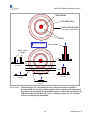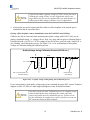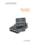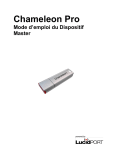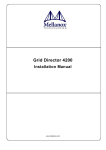
1
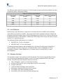
Making connections in a highspeed world 80GHz Wireless Ethernet Links Installation Manual P/N 58000519 Revision D January 2008 AR/GE/FE/U 80/80X Installation Manual Copyright Notice & Disclaimer Copyright © 20042008 BridgeWave Communications. All rights reserved. Printed in the USA No portion of this publication may be reproduced, copied, or distributed without the written consent of BridgeWave Communications. BridgeWave reserves the right to update or change the material in this publication at any time without notice. BridgeWave has made every effort to ensure that the information and the instructions contained in the publication are adequate and is not responsible for any errors or omissions due to typing, printing, or editing of this document. Purchasers of BridgeWave products should make their own evaluation to determine the suitability of each such product for their specific application. BridgeWave’s obligations regarding the use or application of its products shall be limited to those commitments to the purchaser set forth in its Standard Terms and Conditions of Sale for a delivered product. Customers are responsible for obtaining proper operator licenses. This publication has been prepared for professional and properly trained personnel, and the customer assumes full responsibility when using the information herein. Export Control All BridgeWave radio products are restricted commodities that fall under ECCN 5A002 of the Department of Commerce. These products are "ENC restricted" under section 740.17(b)(2) of the Export Administration Regulations (EAR). BridgeWave products may only be exported, reexported, transferred, or retransferred in accordance with Export Administration Regulations. Diversion contrary to U.S. law is expressly prohibited. Product Compatibility While every effort has been made to verify operation of this product with many different communications products and networks, BridgeWave makes no claim of compatibility between its products and other vendors’ equipment. Customer is responsible for thoroughly evaluated this product’s performance in the communications environment in which it will be used. ii 58000519 rev. D AR/GE/FE/U 80/80X Installation Manual Safety CAUTION, WARNING, and DANGER statements have been placed in the text to alert personnel of possible hazards. These statements must be closely observed. The following general safety precautions must be observed during all phases of operation and service of the products covered in this manual. Failure to comply with these precautions or with specific warnings elsewhere in this manual willfully violates standards of design, manufacture, and intended use of the product. BridgeWave assumes no liability for the customer’s failure to comply with these requirements. · The FE/GE/AR80(X) meets all applicable FCC safety requirements for radio equipment; however, it is best to avoid prolonged, unnecessary exposure to the front of the radio while it is operating · The outdoor equipment must be properly grounded to provide some protection against voltage surges and builtup static charges. In the event of a short circuit, grounding reduces the risk of electrical shock. For installations in the U.S.A., refer to Articles 810 830 of the National Electrical Code, ANSI/NFPA No. 70, for information with respect to proper grounding and applicable lightning protection for DC cables. For installations in all other countries, implement protection in accordance with the safety standards and regulatory requirements of the country where the equipment is to be installed. · Do not install or operate this equipment in the presence of flammable gases or fumes. Operation of any electrical instrument in such an environment constitutes a definite safety hazard. · Do not install substitute parts or perform any unauthorized modification to the equipment. Changes or modifications not expressly approved by BridgeWave can void the user’s authority to operate the equipment. iii 58000519 rev. D AR/GE/FE/U 80/80X Installation Manual Regulatory Information This device complies with Part 101 of the FCC Rules. Links installed in the U.S. must be registered with the FCC as provided for in Part 101 of the FCC regulations. For more information contact BridgeWave’s Customer Service via Email [email protected] or call at 4085676906. Equipment Precautions Water and Moisture – The 80GHz System is designed to withstand precipitation conditions typically encountered when installed outdoors. Power Sources This product should only be operated with the type of power supply provided by BridgeWave Communications Inc. iv 58000519 rev. D AR/GE/FE/U 80/80X Installation Manual Table of Contents Copyright Notice & Disclaimer ................ ii 1 2 3 Installation .......................................... 8 Export Control ......................................... ii 3.1 General......................................... 8 Product Compatibility .............................. ii 3.2 Equipment Unpacking................... 8 Safety ...................................................... iii 3.3 Equipment Inventory ..................... 9 Regulatory Information ............................iv 3.4 Installation Tools ........................ 10 Equipment Precautions.............................iv 3.5 Antenna Mount Installation......... 10 Introduction ........................................ 1 3.6 Antenna and Radio Installation ... 14 1.1 Purpose of Manual........................ 1 3.7 Cable Installation........................ 16 1.2 Prior Knowledge........................... 1 3.8 Ice Shield Canopy Installation .... 19 1.3 Contact Information...................... 2 3.9 Antenna Alignment...................... 22 3.10 Auto Calibration ......................... 26 Site Planning ....................................... 3 2.1 General......................................... 3 2.2 Equipment Checklist ..................... 3 2.3 Line of Sight (LOS) ....................... 3 2.4 Link Distance................................ 4 2.5 Antenna Location.......................... 4 2.6 Cabling ......................................... 5 2.7 3.11 QUAL & RSL Test Cable ............ 30 4 Radio Link Status Indicators ........... 32 5 Connecting Network Equipment...... 33 5.1 Network Port Statistics................ 33 Apendix A Troubleshooting................. 34 Grounding & Lightning................. 6 Apendix B RSL Vs. Distance Charts... 36 2.8 Environmental .............................. 7 Std. Limited Warranty & SW License .... 37 2.9 Cabling Diagram .......................... 7 v 58000519 rev. D AR/GE/FE/U 80/80X Installation Manual 1 Introduction 1.1 Purpose of Manual The information in this manual is directed to persons who must perform or coordinate the tasks associated with the process of installing wireless communication devices, and planning communication network applications. 1.2 Prior Knowledge This manual assumes the operator has at least basic experience with and an understanding of wireless technology and some familiarity with configuring and operating networking equipment. Preferably, the person installing this equipment fully understands the information covered in this manual prior to attempting these procedures. DANGER, WARNING and NOTE statements have been placed in various sections throughout this document to alert personnel of possible traffic affecting issues and to provide additional tips and helpful information. These statements should be closely observed. Symbol Description Indicates that personal injury can result if the user does not comply with the given instruction. A DANGER statement will describe the potential hazard, its possible consequences, and the steps to perform to avoid personal injury. Indicates that equipment damage, process failure and/or loss of data can result if the user does not comply with the given instructions. A WARNING statement will describe the potential hazard, its possible consequences, and the steps to perform to avoid serious equipment damage. Provides supplementary information to emphasize a point or procedure, or provides a tip for easier operation. 1 58000519 rev. D AR/GE/FE/U 80/80X Installation Manual 1.3 Contact Information Technical Assistance and Customer Service BridgeWave distributors and resellers are authorized local service providers and are responsible for immediate Tier 1 customer support. If a problem cannot be resolved, contact BridgeWave Customer Service for assistance: Location: Santa Clara, CA USA Email: [email protected] Tech Support Hot Line: +1.408.567.6906 eService Center http://bridgewave.com/support Return Material Authorization (RMA) Should BridgeWave equipment have to be returned for repair or replacement, an RMA number must be obtained in advance from BridgeWave or a local BridgeWave distributor. When returning equipment, be sure to clearly indicate the RMA number on the outside of the shipping carton. BridgeWave eService Center: You can view knowledgebase content, open a ticket, update tickets and request RMAs online 24x7. To view current ticket and RMA status, please goto http://bridgewave.com/support and select ‘eService Center’ to login and enter your support portal. First time users of eService Center will need to submit a request to [email protected], for a login ID and password. A support engineer will contact you with your login ID and password. BridgeWave Sales Email: [email protected] Inside Sales: +1.866.577.6908 2 58000519 rev. D AR/GE/FE/U 80/80X Installation Manual 2 Site Planning 2.1 General Before the start of any installation, a survey of the planned deployment site should be conducted first. The surveying personnel should be fully familiar with the details and requirements needed to successfully install the 80GHz radio system. 2.2 Equipment Checklist We suggest the site survey team may need the following equipment: · Binoculars (not always required) · WAAScapable GPS location device · Tape measure to determine distances for cable runs to ingress points · Digital camera (not always required) · Site survey report form to document and help assess site · Signaling mirror (provided but not always required) · 7090GHz Link Registration Datasheet. Contact BridgeWave Tech Support to learn where one can obtain the latest version of this form. You may Email [email protected] for this request or request it online via eService Center http://bridgewave.com/support. 2.3 Line of Sight (LOS) The 80GHz Wireless Gigabit Ethernet link requires LOS for proper operation. Binoculars and spotting mirrors may be used to assist in the confirmation of LOS. Path planning should include an investigation into future building plans that could block the LOS path, and other longterm incremental obstructions such as tree growth. Intermittent obstructions such as aircraft at a nearby airport should also be considered. 3 58000519 rev. D AR/GE/FE/U 80/80X Installation Manual The following table details the minimum F1 (First Fresnel) clearance needed from obstacles in order to ensure the radios will operate properly. Table 2.31: Minimum Path Clearance Path Length (meters) Minimum F1 Clearance (meters) Path Length (miles) Minimum F1 Clearance (feet) 1000 0.58 0.62 1.9 2000 0.82 1.24 2.7 5000 1.3 3.10 4.3 10000 1.8 6.21 5.9 2.4 Link Distance Measurement of the link distance is important in estimating the link availability and calculating expected Receive Signal Level (RSL). This measurement can be performed using the Latitude and Longitude coordinate readings from a Global Positioning System (GPS) device, which is placed near the proposed locations of the antennas. Additionally GPS reading will be required in order to comply with the FCC registration process. The Minimum 80GHz Link distances are as follows: · AR/GE/FE80: 328 feet (100 meters) · AR/GE/FE80X: 1312 feet (400 meters) To estimate maximum distances and availabilities for a given product and region, BridgeWave’s Path Availability calculator can be used. To obtain the latest version of BridgeWave’s Path Availability calculator, contact BridgeWave’s Customer Service or search eService Center Knowledgebase. 2.5 Antenna Location The optimum location for the antennas must be determined. The ideal location should provide for ease of erecting and mounting the antenna, as well as providing unimpeded LOS to the remote location. The following factors should be taken into account: · · · · · · · Type of mounting—fixed or roofsafe pole mounting. Location of fiber and DC power wiring ingress/egress of the building. Length of cable runs. Confirmed Earth Grounding connection points. Obstructions, including allowances for tree growth. Accessibility of the radio mounting location. Accessibility of the site during and after working hours. 4 58000519 rev. D AR/GE/FE/U 80/80X Installation Manual 2.6 Cabling The installation site should be inspected to determine the run paths for the fiber cable and power cable from the radio equipment to the termination point. Locations for roof penetration should be identified. The routing and securing of all cables should conform to all applicable codes and requirements. Depending on the likelihood of damage due to foot traffic or equipment movement, cabling conduit may be required. The maximum cable run length as specified for the equipment being installed must not be exceeded, refer to Table 2.61 and 2.62 for cable types and limitations. The radio requires LC type connectors on duplex multimode fibers to properly connect between the radio and the users network equipment. Singlemode fiber connections are not supported for use with the standard product. The network equipment end of the fibers should be terminated with connectors that match the user’s network equipment fiber interface. Table 2.61: Maximum Fiber Length Fiber Cable Length Cable Type Up to 270 meters 62.5/125 μm Up to 500 meters 50/125 μm The 80GHz radio includes a 100240 VAC power adaptor, suitable for indoor operation only, that converts the AC voltage from a standard electrical outlet in the wall to DC voltage. For outdoor rated power supply options, contact BridgeWave customer service. The radio requires a minimum of 15.0 VDC at the connector on the radio unit (24.0 VDC maximum) to function properly. When planning the cable run from the indoor AC power adaptor to the radio unit, it is required to use the cable gauge (AWG) indicated below to ensure adequate voltage at the radio. The indoor and outdoor portions of the DC power cabling must conform to all respective indoor and outdoor national and local electrical and building codes; note that requirements may differ for the indoor and outdoor portions of the cabling and that a grounded surge protector is normally required at the point where the cable enters the building. The DC power cabling must consist of two 12 or 14 gauge stranded conductors based on the required cable run length. Table 2.62: Minimum DC Cable Size DC Cable Length Conductor Size Up to 125 meters 14 AWG (2.5mm²) Up to 200 meters 12 AWG (4mm²) Figure 2.61 shows a standard 14gauge wire that has been fitted with the power connectors (provided) for the radio’s internal power supply necessary to mate with the (not provided) DC power 5 58000519 rev. D AR/GE/FE/U 80/80X Installation Manual cables. A standard crimping/splicing tool (not provided) is required to terminate the power connectors onto a 1412gauge cable required for use with the 80GHz. On the radio end no connectors are required; simply screw terminals to appropriate polarity. The DC power cable should be fed into the connector on the casing first and then the green connector attached to the radio after making a strain relief coil around the electronic housing. Figure 2.61: (Left) 14gauge DC power cable terminated to radio end. (Right) DC 14gauge cable from the power supply end. 2.7 Grounding & Lightning Proper grounding of the outdoor equipment reduces electromagnetic interference, provides lightning protection, and protects against electrical discharge. Using improper techniques in lightning prone geographic areas may pose a danger to local personnel. The source and connection points for the buildingtoearth ground in the vicinity of the antenna location should be determined. In addition to grounding the equipment, BridgeWave strongly recommends, and local building codes may require, the DC electrical cable to be protected from electrical surges by a surge suppressor. The surge suppressor must be installed at the point where the DC electrical cables exit/enter the building. 6 58000519 rev. D AR/GE/FE/U 80/80X Installation Manual For more information on recommended accessory devices and kits, contact BridgeWave Sales 2.8 Environmental The structure to which the equipment will be mounted should be adequate to bear all wind and weather conditions. The environmental conditions at the location must conform to the operating environment specified for the equipment. 2.9 Cabling Diagram Figure 2.91 details the equipment and cabling found on a typical installation of BridgeWave’s 80GHz radio equipment. Use of the copper port is optional and is not required for management agent access or for normal data traffic operation. Figure 2.91: Simple Network Diagram 7 58000519 rev. D AR/GE/FE/U 80/80X Installation Manual 3 Installation 3.1 General It is recommended that installation personnel read this section in its entirety prior to installing the BridgeWave System. During a particular phase of installation, the user may refer directly to the applicable subsection. The Installation section is comprised of seven subsections covering the procedures and guidelines for installing the BridgeWave Radio System. Subsections 3.3 through 3.4 contain information necessary to prepare for the equipment installation. Subsections 3.5 through 3.8 covers equipment installation procedures. Subsections 3.9 and 3.10 contain information necessary for aligning the antenna. 3.2 Equipment Unpacking The radio system equipment will arrive in two boxes—one box for the low band radio and one box for the high band radio. Locate the correct box (low band or high band) before beginning installation by checking the label on the outside of the box or on the radio itself. It is recommended that the shipping cartons and packing materials be retained in the event that it is necessary to return any equipment. The radiated polarity can be identified on unpacked radios by the first letter of the polarity V or H (Vertical or Horizontal) on the top of the unit chassis or by the polarization labels. See Figure 3.61 and 3.62 for further details. 8 58000519 rev. D AR/GE/FE/U 80/80X Installation Manual 3.3 Equipment Inventory Following are inventory lists for a typical system: Table 3.31: Radio and Electronics Parts List Qty Description 2 ea. 80GHz radio unit (1 lowband transmit unit & 1 highband transmit unit) 2 ea. Standard Power Supply (Indoor rated, 100240VAC input to 24VDC output) 1 ea. CD with Manuals (1 CD provided per pair of radios) 2 ea. DC power connection set. (Includes 2prong DC plug and 2 ea slip fit plugs/receptacles) 2 ea Antenna and mount kit 1 ea. Signaling mirror 1 ea. Hard reset box 2 ea. RSL / Quality test cable 2 ea. Stainless Steel Screws # 832 X 3/8, Phillips pan head Table 3.32: Antenna and Mount Kit Parts List Qty. Description 1 ea. Antenna 1 ea. Lower pole mount assembly 1 ea. Upper pole mount assembly 1 ea. Antenna mounting plate 2 ea. 3/8 bolts 2 ea. 3/8 lock washers 2 ea. 3/8 flat washer 2 ea. 3/8 nylon washer For more information on recommended accessory devices and spare parts, contact BridgeWave Sales 9 58000519 rev. D AR/GE/FE/U 80/80X Installation Manual The radio is sealed at the factory warranty stickers on the inner (metal) cover of the radio. There is no need to open this cover in the field. Tampering with these seals will void the warranty. 3.4 Installation Tools The following tools, not provided by BridgeWave, are required for installing the radio and the antenna: · Screwdriver, slotted 0.1 inch wide. · Openend wrench 9/16 inch 2 ea. · Openend wrench 1/2 inch. · Ratchet with 6inch extension and 9/16 inch deep socket. · Wire stripper/cutter/crimp tool (1016 gauge). · Electrical tape. · Fish tape for pulling cable. · Cable tie wraps. · Handheld DVM (digital voltmeter) with standard banana plug receptacles. 3.5 Antenna Mount Installation 1. Read these instructions before beginning installation. Caution should be used. Qualified persons experienced with antenna assembly and installation are required for installation. 2. BridgeWave Communications Inc. disclaims any responsibility or liability for damage or injury resulting from incorrect or unsafe installation practices. 3. The antenna has been formed to a very close tolerance parabolic shape. Careful handling and assembly is required to avoid denting the reflector, which would degrade antenna performance. When using the left side radio mount position, the antenna ends up getting rotated by 180 degrees. The drain hole must be open at the bottom and closed off at the top of the antenna to prevent water ingress. · For the 80X, move the bottom drain hole plug to the top drain hole position. · For the Standard 80 remove the four Philips head screws 10 58000519 rev. D AR/GE/FE/U 80/80X Installation Manual from the radome and rotate the radome so the drain hole is at the bottom. Be careful not to contaminate, damage or smudge the shiny coating of the antenna surface or feedhorn and make sure the gasket is evenly seated when reattaching the radome cover. 1. Attach the upper pole mount to the antenna mounting plate. Confirm that the mount is centered as shown. Tighten bolts securely. Figure 3.51: Upper pole mount attached to antenna mounting plate 2. Attach the lower pole mount and azimuth fine adjust as shown. Hardware: Flat washer, bushing (inside eye), flat washer, lock washer, bolt. Figure 3.52: Azimuth fine adjust assembly 11 58000519 rev. D AR/GE/FE/U 80/80X Installation Manual Confirm that the mount is centered as shown. Tighten bolts securly. Figure 3.53: Lower pole mount attached to antenna mounting plate 3. Completed installation of pole mount with right hand offset for the antenna. Note the position of the elevation fine adjust hex nut. The pole mast (not supplied) must be 3.5 to 4.5 inch (89 to 114mm) O.D. SCH40 steel pipe or equivalent. Figure 3.54: Pole mount with right hand offset 12 58000519 rev. D AR/GE/FE/U 80/80X Installation Manual 1. Optional left hand antenna offset mount preparation: · Remove azimuth bolts · Rotate the antenna mounting plate 180º · Replace azimuth bolts · Tighten azimuth bolts Note the position of the elevation fine adjust hex nut. Figure 3.55: Pole mount with optional left hand offset 13 58000519 rev. D AR/GE/FE/U 80/80X Installation Manual 3.6 Antenna and Radio Installation It is critically important during installation to ensure the radios on each side of the link are in the same polarization (horizontalhorizontal or verticalvertical). A link that has a radio on one side of the link set in the horizontal polarization and the other side of the link set in the vertical polarization will not operate properly. It is also critically important that a highband radio is paired with a lowband radio to ensure the system will operate properly. Prior to installation check each radio to verify one is a highband and the other is a lowband version. The label on the radio will indicate the band (blue for high or red for low). 1. Install antenna and radio: The first letter of the designated polarization is stamped onto each unit to identify orientations when the polarity mark is positioned on top: “H” for horizontal. Figure 3.61: 80GHz Unit mounted in horizontal polarity 2. Verify that the four (4) captive 3/816 bolts with lock and flat washer are in place. It is important that all four bolts are tightened evenly (hand tight, 1 to 2 turns each until the lock washer is flattened). Units have captive bolts attached to the radio housing. A 9/16inch openend wrench is required to tighten them. Units have captive bolts attached to the 2’ antenna. A 1/2inch openend wrench is required to tighten them. “V” for vertical polarity. Figure 3.62: 80GHz Unit mounted in vertical polarity 14 58000519 rev. D AR/GE/FE/U 80/80X Installation Manual 3. 4. Course align azimuth (i.e. sidetoside or horizontal) and tighten 4 carriage bolts to secure pole mounts. Loosen the 4 azimuth lock bolts. 5. Adjust eyebolt length using a 9/16” open end wrench to required location. 6. Secure the 4 azimuth lock bolts (tighten untl lock washers are flattend). Figure 3.63: Azimuth adjustment bolts (Note: Antenna not shown for clarity) It is very important that the azimuth bolts are tightened before any elevation adjustment is attempted. The very narrow beam width of these antennas (0.4º and 0.9º) makes it necessary to completely tighten the bolts of the azimuth adjustment while adjusting the elevation and vice versa. 7. Loosen the 2 antenna mounting bolts 8. Rotate elevation fine adjust hex nut as required to set correct elevation (i.e. updown or vertical). Do not try to adjust the elevation fine adjust bolt without first loosening the antenna bolts (step 7). Doing so may damage the brass elevation adjustment pin. 9. Tighten the 2 antenna mounting bolts after correct elevation is set. Figure 3.64: Elevation fine adjustment 15 58000519 rev. D AR/GE/FE/U 80/80X Installation Manual 3.7 Cable Installation 3.7.1 Fiber Cabling 1. Install a duplex multimode fiber from the radio to the network termination equipment (switch or router with 1000BaseX port). The cable should be looped around the inside of the enclosure to provide strainrelief. Do not connect the fibers to the radio’s fiber ports at this time. The connectors on the radio end of the fiber require two LC connectors; the connectors on the switch/router end should mate to the network equipment. 2. Connect fibers at the network equipment. It is important not to connect the fibers to the radio until after aligning the radio as the radio performs an automatic calibration once the fiber is inserted into the radio and this calibration will not operate properly if the radio is not properly aligned. If this inadvertently occurs while the radio is powered on, unplug the fibers and power cycle the radio. 3.7.2 Power Cabling 1. Select indoor location, with easy cable routing to the radio, for the AC power adaptor. Normally it is convenient, but not required, to place the adaptor near the network termination equipment. 2. Ensure the DC wire used is 14gauge type and no longer than 125 meters; or 12gauge and no longer then 200 meters. 3. Connect the provided DC Connectors onto the 14guage wire using a splicing/crimping tool. For the use of 12gauge wire it may be necessary to trim a few strands from the ends of thicker stranded cables to more easily fit the crimp connectors. 4. Install the DC power cable and attach to the AC adaptor using the supplied crimp connectors. Do not connect the power jack to the radio at this time. The fiber and power cables are inserted through the straight through fitting before the 3/4" flexible conduit is connected to the fitting. Ensure that the cables do not get pinched when the conduit is pushed onto the fitting. Both cables should be looped around the inside of the enclosure to minimize tension on the cables when connected to the radio and to maintain proper bendradius of the fiber cable. See Figure 3.7.21 16 58000519 rev. D AR/GE/FE/U 80/80X Installation Manual A 48Volt DC version is available for this product. The power connector is the same but the connector location is slightly moved. The NMS ’Status Page’ reading will still read 24V. Figure 3.7.21: 80GHz power and data cables with service loop for strain relief and proper fiber bend radius. 3.7.3 Ground Cabling The preferred method for grounding the radio unit is to ground the mast to a ground source, since this provides the largest grounding surface contact possible. If this is not possible, then use the following procedure: 1. Attach the lug of the ground cable (not provided) with the radio to one of the two #8 holes at the bottom of the radio using a #832 x ½” long bolt, #8 lock washer and #8 flat washers (not provided). 2. Connect other end of the ground cable to a nearby ground location. 3.7.4 10/100BaseT Surge Suppressor If the 10/100BaseT port is permanently connected to other network equipment (not normally required), it should be connected using Cat5e UTP cables rated for the outdoor and/or indoor environments where the cables will be run. It is essential that the cabling be connected to the radio unit through an Ethernetrated surge suppressor inside of the plastic back cover of the unit, and a surge suppressor should also be used at the point where the cable enters a building or is connected to other outdoor equipment that does not already contain surge suppression hardware. 17 58000519 rev. D AR/GE/FE/U 80/80X Installation Manual For more information on recommended accessory devices and kits, contact BridgeWave Sales Failure to install surge suppression hardware on the UTP cable inside the radio and a second surge suppressor at the building’s pointofentry can expose the radio and network equipment to electrical surges due to lightning strike or other phenomena. Such electrical surges could cause irreparable damage to the radio and/or network equipment not covered by the manufacturer’s warranty. Figure 3.7.41: Ethernet surge suppressor connected to radio 10/100BaseT port 18 58000519 rev. D AR/GE/FE/U 80/80X Installation Manual 3.8 Ice Shield Canopy Installation The Ice Shield assembly is an optional item and can be ordered in kit form through a BridgeWave sales or distribution partner. 3.8.1 Introduction In northern climates, the buildup of ice or snow on antennas can be a problem for millimeter wave radio installations. These problems are twofold: the electrical effect of snow and ice built up on the antenna’s radome; and the mechanical impact of the additional weight of the snow or ice on the antenna and supporting structure. The formation of ice or snow on the antennas radome can cause attenuation of the signal to the point where the link may become severely degraded or unusable. Uneven ice buildup can cause scattering of the signal, which in turn results in standing waves. At 80GHz, ice buildup less than 1mm thick (onequarter wavelength at 80GHz) may result in degraded performance of the link. Such thin layers are not likely to exist for extended periods, as ice tends to melt. In cold climates when the radome is below freezing temperature, ice does not stick to it, thus there is no issue. However in mixed rainsnowice storms, ice can stick to the radome, causing the link to operate at less than its optimal design. Once the ice has hardened and freezes, the added weight of the ice on the antenna increases the wind load on the tower or mast, which may cause premature failure of the mounting structure. As ice breaks apart due to melting, or via its own weight, these large and heavy sheets falling down a tower or mast can cause damage to antennas or other objects mounted below. 19 58000519 rev. D AR/GE/FE/U 80/80X Installation Manual Figure 3.8.11: 80X Ice Shield BridgeWave provides an ice shield kit, designed to combat the buildup of ice on BridgeWave’s 80GHz wireless bridges. These inexpensive ice shields are designed to be easily fitted on radios with integrated antennas or radios with 24” antennas. 3.8.2 Optional Kit The part number for this kit is 51500529 (Available through Sales, see Contact Info section) Refer to the table below for the kit required for your particular application. Each kit contains the necessary materials for the installation of the ice shield on one radio. Two kits are required per link. Qty: Description: 1 ea. Ice Shield Canopy 1 ea. Ice Shield Clamp, 6’ 20 58000519 rev. D AR/GE/FE/U 80/80X Installation Manual 3.8.3 Installation Instructions 1. Remove the protective liner from the plastic canopy 2. Use a screwdriver or 5/16” nut driver to set the hose clamp to the end of its range for maximum opening 3. Slip the hose clamp over the radome so that it loosely sits in approximately the middle of the radome. 4. Slide one end of the plastic canopy under the clamp and slowly bend it around the canopy and work it under the rest of the clamp. 5. Align the canopy to the back edge of the radome and position the clamp 1 to 3” away from the edge 6. Tighten the clamp until snug. (Do Not Overtighten) Remove canopy when it’s not snowing to reduce antenna wind loading 21 58000519 rev. D AR/GE/FE/U 80/80X Installation Manual 3.9 Antenna Alignment 3.9.1 Before Turning On the System 1. Finish the installation as described in Chapter 3.5 and 3.6 2. Ensure fiber cables are still disconnected! 3.9.2 Connect DC power to the radio. 3. Verify that the Power LED is lit. If the Power LED is not lit, carefully use the voltmeter to verify the correct voltage and polarity at the radio connector. Turn off the Power Supply before making any corrections. 4. Repeat steps 1 through 3 on the farend of the link. 3.9.3 Prepare to rough align the radio. 5. Connect RSL test lead cable to radio and place voltmeter with readings in view. 6. Loosen the pole mount brackets enough to allow you to swing the unit horizontally. 7. Reference Chapter 3.5 for illustration of antenna mount bolts and their purpose. 3.9.4 Rough align the radio antennas 8. Set the radio terminal to the predefined azimuth if available. If not, you may utilize binoculars or signal mirror to locate the far end radio location. 9. If you can see the farend radio terminal estimate the alignment visually and tighten the pole mount brackets with fine adjustment bolt set to the middle of adjustment range. 10. Ensure the horizontal adjustment bolts are snug; only tighten bolts one quarter of a turn. 11. Slightly rotate each antenna up/down for best vertical alignment and left/right for best horizontal alignment by finding the maximum RSL voltage reading. 12. To ensure that the antennas are not aligned on a sidelobe, they must be rotated at least ten degrees on each side of the visuallyperceived alignment center to ensure that the true maximum RSL voltage is found. The width of the center beam is only 0.4º (80X) or 0.9º (80) and the first sidelobe beam is only 1 degree off from center. Set the antenna in the position that results in the highest RSL voltage reading. 22 58000519 rev. D AR/GE/FE/U 80/80X Installation Manual 13. Repeat these steps on far end radio. 3.9.5 Fine Adjustment 14. Ensure to loosen the “fine adjustment” bolt (the small eye bolt). 15. Pan antenna slowly from left to right and capture the highest RSL voltage peak. 16. See Figure 3.9.51 below to help guide you in obtaining the highest RSL voltage reading. 17. Tighten down the azimuth adjustment bolts. 18. Loosen the two bolts holding the antenna to the antenna mount. 19. The vertical fine adjustment bolt is not designed to be tightened; use the “hex nut” to fine (and course) adjust the elevation (vertical position) to highest RSL value. 20. While monitoring the voltmeter, begin to align the vertical position of the antenna to obtain the highest RSL voltage level. 21. Once completed, this fine adjustment must be repeated at the remote end of the system, if you have not obtained the “target” RSL voltage for the given path distance (see RSL Vs. distance chart in Appendix B). 22. If you have not obtained the “target” RSL voltage for the given path distance (or you want to further improve it), you will need to realign the antenna, go back to the original site you started with and restart steps 1421 and realign again. See Figure 3.9.51 below of a conceptual illustration of the antenna beam to keep in mind while you perform a re alignment. 23. Once again, the very narrow beam width of these antennas (0.4º and 0.9º) makes it necessary to completely tighten the bolts of the azimuth adjustment while adjusting the elevation and vice versa. Verify that the RSL voltage falls within the expected range based on the graph in Appendix B. 23 58000519 rev. D AR/GE/FE/U 80/80X Installation Manual Main Beam First Sidelobe Second Sidelobe (sometimes undetectable) Nulls Center Location Target Voltage Below Target Voltage Common “First Try” Possible “First Try” Possible “First Try” Possible “First Try” Figure 3.9.51: This illustration is a conceptualized cross section of a beam to exemplify a horizontal RSL level voltage reading against relative locations with an assumed fine tuned vertical position. Keep in mind how narrow the beam is at 80GHz, the 3dB beam width for 80GHz is 0.9º with 12” antenna and 0.4º for 24” antennas with the extended range models 80X. 24 58000519 rev. D AR/GE/FE/U 80/80X Installation Manual 3.9.6 Locking Down Radio Antenna 24. After the target RSL level has been achieved, ensure all bolts are tightened evenly, securely and ensure the RSL voltage remains unchanged after tightening is completed. 25. The very narrow beam width of this antenna (0.4º and 0.9º) makes it necessary to completely tighten the bolts of the azimuth adjustment while adjusting the elevation and vice versa. 26. Always evenly tighten bolts in small fractions at a time to ensure minimum change to your completed alignment. 3.9.7 Connecting the Fiber Connect the fiber cable to one of the radios at a time. The fibers should already be connected to active network equipment. The fiber integrity indication on the network equipment could show up or down independent of the RF link status. 3.9.8 Auto Calibration 27. Once the fiber is connected to the radio, the radio will begin an internal link calibration. 28. During this time the Link Up LED will blink for up to 120 seconds. 29. Wait until the Link Up LED is lit solid 30. Verify the Link Quality voltage is 3.03.3V (i.e., error free). Repeat steps (3032) for the far end radio. For more details on Auto Calibration see section 39 below 3.9.9 Remove the Test Cable 31. Remove the test cable from the radio, replace the rear plastic cover and hand tighten the back cover nut to the point where the back cover stops (i.e. when it hits the metal ring on the back metal plate). The installation is now complete. The most important alignment ‘tool’ for these models is care and patience! It is recommended that these models be aligned with personnel present at both ends of the link, and the installers should allow 90 minutes to optimally align these units. 80 and 80X antennas exhibit narrow beam widths of 0.9º and 0.4º. Link distances are great and alignment becomes more critical. 25 58000519 rev. D AR/GE/FE/U 80/80X Installation Manual 3.10 Auto Calibration The Auto Calibration feature scans the receive signal across the entire (broad) band and flattens the levels, much like the equalizer on your home or car stereo. The radio system is said to be in “Alignment Mode” when it is first powered up with no fiber connected. The Auto Calibration mode is triggered ON as soon as the fiber cable is connected. The fiber interface of the radio terminal needs to detect an optical signal of the appropriate wavelength. This requires the fiber optic cables be connected to a 1000BaseX port on an Ethernet device (switch, router, media converter, etc.) or this can be accomplished with a fiber optic loopback cable by connecting the fiber output of the radio into the fiber input of the radio. If used, the loopback cable should only be connected long enough for autocalibration to start and should be removed immediately. The radio terminal indicates the Auto Calibration by flashing the Link LED on/off this cycle lasts for up to 120 seconds. Autocalibration is a required step per installation once antenna alignment is completed. 3.10.1 AdaptRate™ Fiber Calibration Procedure (AR80 and AR80X only) In order for an Adaptive Rate link to operate correctly, it is especially critical to ensure the following process is followed exactly. If you feel this process may not have been followed or you wish to re attempt the process, be sure to first power down both radios, remove any fiber connection before turning the system on. This will get you back to original factory radio calibration settings and place the radio link in “alignment mode”. START: 1. First, with a local PC, view each radio's Setup page and make sure the operating mode is set to AR and that the Installation Auto Calibration is 'enabled' at both ends. The default value is ‘enabled’. VERIFICATION: Double check this setting on both radios. 2. On initial Power up, do not connect any fiber cables VERIFICATION: It is best to physically disconnect any fiber cables from the radio unit ports, rather than just relying on the far ends of the cables being disconnected. 3. Upon completing the antenna alignment procedure, make sure both ends have a minimum of 2VDC in Quality voltage, if not, further alignment may be required. Small fluctuations are okay. 26 58000519 rev. D AR/GE/FE/U 80/80X Installation Manual If you do not obtain a Quality voltage of 2VDC, do not proceed to calibrate the system. Ensure you are aligned and achieve your target RSL level. This can be confirmed for your path distance by looking up the RSL voltage to distance curve in Appendix B. 4. At this point you need to connect the fiber cable (or a fiber loopback if no network gear is terminated to the far end of the fiber). If using a fiber loopback, remove immediately when the Link LED starts blinking. Calibrate one side at a time and while monitoring the Quality voltage with DVM. Verify you are getting a 'quadruple hump'. i.e. voltage will rise, drop, rise, drop, and rise again, as illustrated below. It should end with a 3.0VDC to 3.3VDC reading on your DVM. Also verify the radio ‘Link LED’ is also ‘flashing’ on/off during this process. See Figure 3.10.11 for an illustration of the Quality Voltage as it fluctuates during the calibration process. Calibrating 100Mbps mode Fiber connected, Radio Link LED starts flashing 10 sec. Calibrating 1000Mbps mode 1V 2.0 3.3VDC 2V 3V 3.3V Quality Voltage during Calibration Process (90120 sec.) Radio Link LED stops flashing Figure 3.10.11: Quality Voltage reading during Auto Calibration process If you cannot obtain a good quality voltage and you have obtained the target RSL, contact Technical Support at (408) 5676906 or email [email protected] for further assistance. You must wait for the Auto Calibration process to complete on one radio terminal before auto calibrating the remote radio and ensure both radios pass the calibration process. Failure to wait for the calibration to complete may result in a failure to create an RF connection between radio terminals. 27 58000519 rev. D AR/GE/FE/U 80/80X Installation Manual At this point, open the Status page from the unit’s NMS interface and ensure the Radio TX and RX is operating at 1000 Mbps for both radios. Click the refresh button a few times to ensure it is a good reading. If all indicators are good, then go to the next steps. If not, then go back to step 1 or contact BridgeWave Technical Support for assistance. 5. Go to Statistics page and reset the stats for each radio end. 6. Perform a ping test. Open two command line windows and ping the local and remote management agent. Factory default IPs are; 192.168.0.1 for lowband and 192.168.0.2 for highband and perform a ping to both ends and wait a few minutes, ensure you are getting responses from the local and remote management agents. 7. Review statistics page results and ensure packets are being transmitted, received, and there are no excessive error conditions. 8. If all is performing well, you must now 'disable' the InstallationAuto Calibration option on the Setup page of each radio. 3.10.2 Installation AutoCalibration Feature (AdaptRate™ models only): This feature should be disabled only after the radio system has been completely installed and calibrated as described above. In the NMS ‘Setup’ screen, select Installation AutoCalibration to ‘Disable’ and press the ‘Submit new Values button at the bottom of the screen Figure 3.10.21: Installation AutoCalibration Setting (AUTO CALIBRATION FINISHED) 28 58000519 rev. D AR/GE/FE/U 80/80X Installation Manual Failure to ‘Disable’ the Installation AutoCalibration option can trigger an inadvertent recalibration of the system, under certain power failure conditions. 3.10.3 Forced ReCalibration Option 1: Use the AutoCal function in the NMS ‘Maintenance screen. This function will store the calibration values in nonvolatile memory. Option 2: Enable “installation auto calibration” in the NMS and ‘Apply Settings'. Disconnect the DC power and fiber optic cables from the radio. Power up the radio while the fiber is still disconnected. The Auto Calibration will start as soon as the fiber optic cable is reconnected to the radio terminal. When a radio is power cycled with the fiber connected to network equipment, the radio will use the calibration values stored in nonvolatile memory from the last successful autocalibration process even if the enable AutoCal setting being set to ‘Enable’. The radio link will come up immediately. When a radio has “Installation Auto Calibration” disabled, the radio will use the calibration values stored in nonvolatile memory from the last successful autocalibration process, regardless of the fiber interface connected to network equipment or not. Should moving the link to a new location or realignment of the link become necessary, the link must be recalibrated per the auto calibration procedure described in Section 3.10. 29 58000519 rev. D AR/GE/FE/U 80/80X Installation Manual 3.11 QUAL & RSL Test Cable The alignment procedure is optimized through the use of the provided test cable. This test cable is designed for use with a digital voltmeter (not provided) to read the Link Quality and Receive Signal Level (RSL) voltage generated by the radio’s receiver. See Figure 3.111. Figure 3.111: Supplied test cable for measuring Link Quality and Receive Signal Level voltages 1. To read the RSL value of the radio, insert GND (ground) and RSL banana plugs into the voltmeter. Note the RSL voltage. The voltage may be fluctuating; in this case, note the maximum value seen. 2. To read the Link Quality value of the radio, insert GND (ground) and QUAL banana plugs into the voltmeter. Note the Link Quality voltage. After the radios have performed an auto calibration the quality voltage should read 3.03.3VDC if the link is aligned on the main antenna beam and there are no obstructions (i.e., trees, buildings, etc…) in the path, the link distance is within the operating parameters of the radio (see Section 2.4 above), and it is not raining heavily. 30 58000519 rev. D AR/GE/FE/U 80/80X Installation Manual 3.3 Correctable Errors Detected 3.0 QUAL Voltage (VDC) NO ERRORS 2.0 Uncorrectable Errors Detected 1.7 CORRECTED ERRORS UNCORRECTED ERRORS 0.3 Deframer Unlocked (Link Down) 0.0 0 0 Errors Figure 3.10.32: Quality Voltage Graph · Quality Voltages between 3.0V and 3.3V indicate PRE and POST FEC errorfree wireless link. · Quality Voltages between 2.0V and 3.0V indicate a low rate of errors that the forward error correction will correct. The lower the voltage, the more errors are being corrected. · Quality Voltages between 0.3V and 1.7V indicate excessive PREFEC errors in the wireless link, some of which cannot be corrected by the FEC. To indicate this change in error performance, the quality voltage will drop from 2.0V to 1.7V in a single step. · Quality Voltages below 0.3V indicate an unlocked deframer condition. This will be recognized as a linkdown condition. 31 58000519 rev. D AR/GE/FE/U 80/80X Installation Manual 4 Radio Link Status Indicators During normal operation, the following conditions should exist at the radio, as shown in Figure 41: · The Power LED should be lit—solid green; · The 1000BaseX (Fiber) LED should be lit—solid green; · The Radio Link Up LED should be lit—solid green; · The Link Quality BER voltage normally should be 3.03.3v when it is not raining. Figure 41: LED's indicating power, RF link is up and operational, and fiber connected to network equipment The 80GHz system does not require periodic maintenance. However, each end of the link should be periodically inspected for visible damage or excessive accumulation of dirt on the antenna’s radome. 32 58000519 rev. D AR/GE/FE/U 80/80X Installation Manual 5 Connecting Network Equipment The networking equipment that will be connected to the 80GHz System should be prechecked to ensure it operates properly backtoback over a wired connection. Once this has been confirmed, it will save troubleshooting steps if a traffic problem arises after the radio is installed and connected to the network equipment. The 1000BaseX interface is factory preconfigured for autonegotiation and flow control enabled. Autonegotiation and flow control can be disabled via the NMS. The 10/100BaseT interface ships from the factory with autonegotiation enabled, and cannot be configured otherwise. The radios support all standard Ethernet frame sizes, up to 1632 bytes for untagged or 802.1q VLANtagged frames. 5.1 Network Port Statistics If the capability exists in the network equipment connected to the 80GHz System, verify the following: · Link integrity · There are no receive errors on the link · Network traffic is flowing in both directions For configuring the radio’s Management Agent, please goto the NMS Manual. It can be found in the product downloads section online; http://www.bridgewave.com/support/downloads.cfm 33 58000519 rev. D AR/GE/FE/U 80/80X Installation Manual Apendix A Troubleshooting The following table provides a summary of possible problems you might encounter while installing a BridgeWave 80GHz link, along with possible causes and their solutions. Extensive troubleshooting support and knowledgebase articles are available at the BridgeWave eSupport knowledgebase online at: http://bridgewave.com/support/kbrma.htm Contact BridgeWave support to obtain a login account. Table A1: Troubleshooting Problem Possible Cause Resolution No power to radio Wrong polarity of supply voltage Use a DVM to determine the polarity and voltage on the DC cable. (See Section 3.7.2) The supply voltage measured at the radio (when connected) is below 15VDC The cable run is too long or the cable gauge is too small. Shorten the length of the cable or use larger gauge cable. (See section 3.7.2) Fiber connector not inserted properly Check fiber connections at radio and at network equipment. Inconsistent fiber port configuration between radio unit and connected switch or router. Verify the configuration of the network equipment. Both ports must either be set to auto negotiate or each must be set to not autonegotiate with flow control disabled. One or both of the fibers have been damaged Use a loopback connector at the radio to verify the radio is OK, repeat at the networking equipment. Visually inspect the fiber cable. Radio link is down AND LSP mode enabled. Operation normal. Check RF status of both radios and LSP option of both radios NMS Setup tab. Check for rain event or other obstruction in RF path, or radio is out of alignment. Incorrect calculation of link distance Verify that the calculation tool used and the GPS used both have the same annotation system (degree hours minutes seconds or degree with a decimal value) Fiber light lit at radio but not on network equipment RSL voltage lower then expected 34 58000519 rev. D AR/GE/FE/U 80/80X Installation Manual Low link quality voltage Cannot connect to radio network management agent Antennas aligned on side lobes Repeat antenna alignment procedure. Radios set to different polarizations Verify that both radios are mounted in the same polarization. (see section 3.6) Installed two high or two low band radios in one link Verify that one end of the link is high and the other end is a low band radio Test cable not inserted into test port on radio properly Ensure test cable is completed inserted into the test port of the radio. Make sure that you are using correct RSL voltage table. If table is for a different product, consult the correct product manual. Antennas are not aligned for maximum RSL Verify antenna alignment, use instructions provided in sections 3.63.9 Auto calibration not successfully completed Repeat autocalibration procedure. Interference This is unusual unless other radios using the same spectrum are colocated. Check for possible interference by turning off the radio at the other end of the link and verify the RSL voltage on the local site drops below 0.2V . Test cable not inserted into test port on radio properly Ensure test cable is completely inserted into the test port of the radio. Incorrect IP address configuration on radio or PC Verify Ethernet connections are up, verify IP address, check for IP address conflicts, clear ARP cache on PC, and/or perform hard reset on radio unit (see NMS manual). Management agent access is blocked through one or more interfaces Verify management access configuration on Setup t, and change if necessary. Try accessing agent through other interfaces (fiber, copper, radio link) 35 58000519 rev. D AR/GE/FE/U 80/80X Installation Manual Apendix B RSL Vs. Distance Charts GE/AR80/FE80U RSL Voltage vs. Distance (Align Antennas to Max voltage and confirm RSL is above Min value) 3.2 ABOVE CALIBRATED RANGE 3 RSL Voltage (VDC) 2.8 2.6 Min Voltage 2.4 2.2 2 1.8 1.6 1 2 3 4 5 6 7 8 9 10 11 Distance (km) GE/AR80X RSL Voltage vs. Distance (Align Antennas to Max voltage and confirm RSL is above Min value) 3.2 ABOVE CALIBRATED RANGE 3 RSL Voltage (VDC) 2.8 2.6 Min Voltage 2.4 2.2 2 1.8 1.6 3 4 5 6 7 8 9 10 11 12 13 Distance (km) 36 58000519 rev. D AR/GE/FE/U 80/80X Installation Manual Std. Limited Warranty & SW License THE FOLLOWING WARRANTY AND SOFTWARE LICENSE GRANT APPLY ONLY FOR BRIDGEWAVE COMMUNICATIONS, INC. (“BRIDGEWAVE”) PRODUCTS PURCHASED THROUGH BRIDGEWAVE AUTHORIZED CHANNEL PARTNERS WITHIN THE UNITED STATES OR CANADA BY THE ORIGINAL END PURCHASER (“BUYER”). IF BRIDGEWAVE PRODUCTS WERE OBTAINED THROUGH OTHER CHANNELS, THE FOLLOWING PROVISIONS DO NOT APPLY AND THE SELLING PARTY SHOULD BE CONTACTED FOR INFORMATION ON ANY PRODUCT WARRANTIES AVAILABLE. The following terms apply to the Buyer’s use of BridgeWave hardware products (“Products”) and software products (“Software”), except to the extent otherwise provided in (a) a separate written agreement between Buyer and BridgeWave or (b) a “clickon” license agreement as part of the installation and/or downloading process for a particular Software. To the extent of a conflict between the provisions of these documents, the order of precedence shall be (1) the written agreement, (2) the clickon license agreement, and (3) this Limited Warranty and Software License. LIMITED HARDWARE WARRANTY Limited Hardware Warranty. Subject to limitations below, for a period of twelve (12) months (the “Warranty Period”) after shipment to Buyer of the Hardware by BridgeWave or an authorized distributor of BridgeWave products, BridgeWave warrants that the Products, under normal use and service, shall be free in all material respects from defective design, material and faulty workmanship and shall operate in all material respects in compliance with the functional specifications, designs, installation instructions, Product descriptions or technical requirements published by BridgeWave in its Product Manual (“Specifications”). The foregoing warranty includes Basic Support Services (as defined at www.BridgeWave.com) from BridgeWave during the Warranty Period. These warranties are provided for the benefit of the original Buyer only. Except for the foregoing warranties, the Products are supplied “AS IS”. Remedies for Breach of BridgeWave Warranty. If a Product is in breach of BridgeWave’s warranty during the Warranty Period, BridgeWave shall, as the sole and exclusive remedy, within thirty (30) calendar days after BridgeWave’s receipt of the returned Product, repair, replace (with new or refurbished units) or modify, as BridgeWave may solely elect, the Product as necessary so that the Product complies with the applicable Warranty, or at BridgeWave’s option, refund to the Buyer the Buyer’s purchase price paid for the Product. Before returning any Products to BridgeWave, Buyer must follow the steps set forth in the Trouble Shooting and Return Merchandise Procedure explained at www.BridgeWave.com. Any Product returned to BridgeWave must be shipped according to BridgeWave’s instructions with a properly issued RMA number clearly visible on the outside of the packaging. All Products returned to BridgeWave shall be shipped DDP (Delivery and Duties Paid) by Buyer to BridgeWave’s designated service facility. BridgeWave shall prepay return freight charges on repaired or replaced Products when BridgeWave determines, in its sole judgment that a breach of warranty occurred. BridgeWave may charge its standard rates for any repair or replacement work performed on returned Product that was not in breach of the warranties herein. Replacement Product Warranty. The Warranty Period of replacement Product (whether new or refurbished) shall commence upon the shipment of the replacement Product to Buyer and shall expire on the later of ninety (90) days after shipment date or the last day of the original Warranty Period with respect to the replaced Product. All replaced parts or Product shall become the property of BridgeWave. Limitation on Warranty. Except where they are embedded in the Products, nonBridgeWave manufactured products provided to Buyer are excluded from any BridgeWave warranty, but may be subject to a warranty provided by the original manufacturer. BridgeWave shall supply a copy of any such warranty to Buyer on specific written request. BridgeWave warranties are void if: (a) Buyer integrates or assembles the Product with other products unless integrated or assembled in accordance with applicable Specifications; (b) the Product is wired, repaired or altered by anyone other than BridgeWave or an authorized representative of BridgeWave in strict accordance with the applicable Specifications; (c) the Product is improperly handled, stored, installed or maintained; (d) the Product is used in violation of the applicable Specifications or BridgeWave’s instructions or subjected to misuse, neglect, accident, abuse or suffers damage due to acts of nature; or (e) the Product is disassembled or its housings are removed by any person other than a BridgeWaveauthorized technician. EXCLUSION OF CERTAIN WARRANTIES. THE FOREGOING WARRANTIES ARE IN LIEU OF AND EXCLUDE ALL OTHER EXPRESS AND IMPLIED REPRESENTATION OR WARRANTIES, INCLUDING BUT NOT LIMITED TO, PRODUCT NONINFRINGEMENT, OR WARRANTIES OF MERCHANTABILITY, FITNESS FOR A PARTICULAR PURPOSE, SATISFACTORY QUALITY, ERROR FREE NON INTERRUPTED OPERATIONS, PROTECTION FROM UNAUTHORIZED INTRUSION OR ATTACK OR OPERATION AT A SPECIFIED RANGE OR SIGNAL AVAILABILITY OR ARISING FROM A COURSE OF DEALING, LAW, USAGE OR TRADE PRACTICE. AS EACH PRODUCT IS UNIQUE, BRIDGEWAVE DISCLAIMS LIABILITY FOR OPERATION OF THE END USER NETWORK AS A WHOLE UNDER ANY WARRANTY PROVIDED HEREIN. TO THE EXTENT A WARRANTY CANNOT BE EXCLUDED BY LAW, SUCH WARRANTY IS LIMITED IN DURATION TO THE WARRANTY PERIOD. BECAUSE SOME STATES OR JURISDICTIONS DO NOT ALLOW LIMITATIONS ON WARRANTY DURATION, THE ABOVE LIMITATION MAY NOT APPLY. THIS WARRANTY GIVES SPECIFIC LEGAL RIGHTS WHICH MAY BE IN ADDITION TO OTHER RIGHTS WHICH VARY FROM JURISDICTION TO JURISDICTION. THIS DISCLAIMER AND EXCLUSION SHALL APPLY EVEN IF THE EXPRESS WARRANTY SET FORTH ABOVE FAILS OF ITS ESSENTIAL PURPOSE. SOFTWARE LICENSE Software License. BridgeWave provides Buyer a nonexclusive, nontransferable limited license (“License”) to use, solely as embedded in, for execution on or for communication with the Products, the object code (and not the source code) of its Software. For purposes of this License, Software shall include any BridgeWave provided documentation, component parts, user interfaces, modifications, upgrades, updates, bug fixes, corrections, backup copies and new releases. Buyer’s use of the Software shall also be limited by any other restrictions set forth in BridgeWave’s quotation or in BridgeWave’s product catalog, user documentation or web site. 37 58000519 rev. D AR/GE/FE/U 80/80X Installation Manual Title to Software. Title to the Software, and to any source code for the Software, shall at all times remain solely and exclusively with BridgeWave. Buyer agrees not to take any action inconsistent with such title. Buyer agrees that the Software, including the design and structure of individual programs, constitutes the trade secrets or copyrighted material of BridgeWave. Buyer agrees not to disclose such material in any form to any third party and to implement reasonable security measures to protect such material. License Restrictions. BridgeWave reserves all other rights to the Software not specifically licensed hereunder. Buyer has no right to, and agrees not to sell, transfer, rent, copy, reverse engineer, reverse compile, decrypt, or reduce to human readable form to gain access to trade secrets or confidential information, modify or create derivative works of, or grant to any third party any rights in the Software, or permit any third party to do any of these prohibited acts, without BridgeWave’s prior written consent. Buyer agrees to protect the Software licensed hereunder in a manner consistent with the maintenance of BridgeWave’s ownership and proprietary rights therein, including displaying of any copyright and trademark notices in all Software as incorporated by BridgeWave. Term and Termination. This License is effective until terminated. Buyer may terminate this License at any time, provided that Buyer’s termination does not entitle Buyer to any refund of purchase or license fees. BridgeWave may terminate Buyer’s rights under this License immediately upon written notice if Buyer fails to comply with any provision of this License. Upon termination, Buyer must destroy all copies of Software in its possession or control. Export. Software and Products, including technical data, may be subject to U.S. export control laws, including the U.S. Export Administration Act and its associated regulations, and may be subject to export or import regulations in other countries. Buyer agrees to comply strictly with all such regulations and acknowledges that Buyer has the responsibility to obtain licenses to export, reexport, or import Software and Products. Restricted Rights. BridgeWave’s commercial software and commercial computer software documentation is provided to United States Government agencies in accordance with the terms of this Limited Hardware Warranty and Software License, and per subparagraph “©” of the “Commercial Computer Software – Restricted Rights” clause at FAR 52.22719 (June 1987). For DOD agencies, the restrictions set forth in the “technical Data Commercial Items” clause at DFARS 252.2277015 (Nov 1995) shall also apply. LIMITATION OF REMEDY AND LIABILITY PROVISIONS EXCLUSIVE REMEDIES. THE REMEDIES SET FORTH IN THIS LIMITED WARRANTY AND SOFTWARE LICENSE ESTABLISH THE ENTIRE OBLIGATION OF BRIDGEWAVE AND BUYER’S SOLE REMEDY IN REGARD TO CLAIMS RELATING TO BREACH OF WARRANTY OR INTELLECTUAL PROPERTY RIGHTS INCLUDING BUT NOT LIMITED TO CLAIMS DIRECTED TO THE INFRINGEMENT OR MISAPPROPRIATION OF PATENTS, COPYRIGHTS, TRADE SECRETS AND OTHER PROPRIETARY RIGHTS FOR THE PRODUCTS. NO CONSEQUENTIAL DAMAGES. IN NO EVENT SHALL EITHER PARTY, OR EITHER PARTY’S SUPPLIERS, OFFICERS, DIRECTORS, EMPLOYEES, AGENTS, SHAREHOLDERS OR CONTRACTORS (“RELATED PARTIES”), BE LIABLE TO THE OTHER PARTY OR ITS RELATED PARTIES FOR CONSEQUENTIAL, INDIRECT, INCIDENTAL, SPECIAL, PUNITIVE OR EXEMPLARY DAMAGES OR FOR COST OF COVER, LOST REVENUES, LOST PROFITS OR LOST DATA OR OTHER ECONOMIC LOSS ARISING FROM ANY CAUSE INCLUDING BUT NOT LIMITED TO BREACH OF WARRANTY, BREACH OF CONTRACT, TORT, STRICT LIABILITY, OR FAILURE OF ESSENTIAL PURPOSE EVEN IF BRIDGEWAVE HAS BEEN ADVISED OF THE POSSIBILITY OF SUCH DAMAGES. THE FOREGOING LIMITATIONS SHALL APPLY EVEN IF THE ABOVESTATED WARRANTY FAILS OF ITS ESSENTIAL PURPOSE. BECAUSE SOME STATES OR JURISDICTIONS DO NOT ALLOW LIMITATIONS OR EXCLUSIONS OF CONSEQUENTIAL OR INCIDENTAL DAMAGES, THE ABOVE LIMITATION MAY NOT APPLY TO BUYER. LIMIT ON LIABILITY. THE MAXIMUM LIABILITY OF BRIDGEWAVE, AND ITS RELATED PARTIES, TAKEN AS A WHOLE, FOR ANY AND ALL CLAIMS IN CONNECTION WITH THE PRODUCTS AND SOFTWARE, INCLUDING BUT NOT LIMITED TO CLAIMS FOR BREACH OF WARRANTY, BREACH OF CONTRACT, TORT, STRICT LIABILITY, FAILURE OF ESSENTIAL PURPOSE OR OTHERWISE, SHALL IN NO CIRCUMSTANCE EXCEED THE PURCHASE PRICE PAID BY BUYER TO BRIDGEWAVE OR BRIDGEWAVE’S AUTHORIZED CHANNEL PARTNERS FOR THE PRODUCTS AND SOFTWARE. Statute of Limitations. Any action for breach of or to enforce any right under this Limited Hardware Warranty or Software License shall be commenced within one (1) year after the cause of action accrues, or reasonably could have been discovered, or it shall be deemed waived and barred. Administrative Provisions. This Limited Hardware Warranty and Software License shall be governed by and construed in accordance with the laws of the State of California, without reference to principles of conflict of laws, provided that for customers located in a member state of the European Union, Norway or Switzerland, English law shall apply. The United Nations Convention on the International Sale of Goods shall not apply. If any portion hereof is found to be void or unenforceable, the remaining provisions of the Limited Hardware Warranty and Software License shall remain in full force and effect. Except as expressly provided herein, the Limited Hardware Warranty and Software License constitutes the entire agreement between the parties with respect to warranties on the Hardware and Licensing of the Software, and supersedes any conflicting or additional terms contained in any prior or contemporaneous discussion, negotiation or agreement, including those in any purchase order or order acknowledgment. 38 58000519 rev. D