1
VIDEO CASSETTE RECORDER
SERVICE MANUAL
SV-627X/425X/223X/627F/425F/627B/225B/625G/425G/620I/C80K/C30K/120W/SVR-629
ELECTRONICS
SV-627X/625X/623X/6233X/621X/620X/520X
SV-425X/4215X/4213X/421X/225X/2253X
SV-223X/2233X/221X/2215X/2213X/220X
SV-627F/623F/620F/425F/423F/420F/223F/220F
SV-627B/625B/623B/620B/225B/223B/220B
SV-625G/620G/600G
SV-425G/4253G/4203G/420G/225G/220G/2203G
SVR-629/623
SV-620I/C620K/C80K/C35K/C30K/C10K/120W
SERVICE
For mechanical disassembly and adjustment, refer to the “Mechanical Manual” (DX-9R
VIDEO CASSETTE RECORDER
AC68-00001A).
CONTENTS
1. Precautions
PLAY
POWER
2. Alignment and Adjustment
SV-627X/627B/620G/620G/620I/C620K/SVR629
EJECT
3. Exploded View and Parts List
F.F
REW
POWER
REC
PROG
STOP
LINE IN 2
L R
AUDIO
VIDEO
SV-625X/623X/620X/425X/225X/627F/623F/425F/423F/223F
SV-625B/623B/620B/225B/625G/425G/225G/C10K
REW
F.F
POWER
LINE IN 2
REC STOP
PROG
PLAY
AUDIO
VIDEO
SVR-623/SV-C80K
EJECT
STOP
POWER
PLAY
REC
PROG
REW F.F
AUX
L R
AUDIO
VIDEO
POWER
EJECT
REW
F.F
AUX
REC
PROG
VIDEO
STOP
AUDIO
SV-6233X/2253X/2233X/4256G/4203G/2203G/C35K/120W
POWER
EJECT
LINE IN 2
REC
PROG
VIDEO
AUDIO
SV-C30K
STOP
PLAY
4. Electrical Parts List
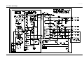
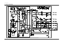
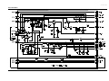
5. Schematic Diagrams
EJECT
SV-621X/520X/421X/4215X/4213X/223X/221X/2215X/2213X
SV-220X/620X/420X/220X/223B/220B/620G/420G/220G
© Samsung Electronics Co., Ltd. JAN. 1999
Printed in Korea
AC68-00128A
Manual
IMPORTANT SERVICE GUIDE
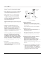
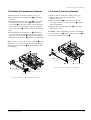
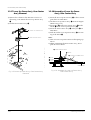
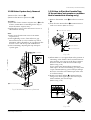
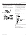
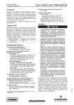
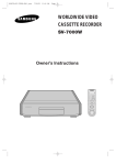
3 MODE SWITCH (PROGRAM SWITCH) ASSEMBLY POINT
1) When installing the ass’y full deck on the Main PCB, be sure to align the assembly point of mode switch.
ASSEMBLY POINT
Fig. 1
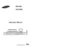
3 HOW TO EJECT THE CASSETTE TAPE
(If the unit does not operate on condition that tape is inserted into housing ass’y)
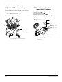
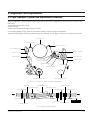
1) Remove the Holder Worm Œ and the gear worm ´. (See Fig. 2)
2) Turn the Gear Worm Wheel ˇ counterclockwise in the direction of arrow with screw driver. (See Fig. 2)
3) When Slider S, T are approached in the position of unloading, rotate holder Clutch counterclockwise after inserting screw driver in the
hole of frame’s bottom in order to wind the unwounded tape. (Refer to Fig. 3)
(If you rotate Gear Worm Wheel continuously when tape is in state of unwinding, you may cause a tape contamination by grease and
tape damage. Be sure to wind the unwounded tape in the state of set horizontally.)
4) Rotate Gear Worm Wheel ˇ counterclockwise using screw driver again up to the state of eject mode and then pick out the tape.
(Refer to Fig. 2)
ˇ GEAR WORM WHEEL
SCREW DRIVER
FRAME
´ GEAR WORM
ΠHOLDER WORM
Fig. 2
Fig. 3
1. Precautions
1. Be sure that all of the built-in protective devices are
replaced. Restore any missing protective shields.
2. When reinstalling the chassis and its assemblies, be
sure to restore all protective devices, including :
control knobs and compartment covers.
3. Make sure that there are no cabinet openings
through which people--particularly children
--might insert fingers and contact dangerous
voltages. Such openings include the spacing
between the picture tube and the cabinet mask,
excessively wide cabinet ventilation slots, and
improperly fitted back covers.
(READING SHOULD
NOT BE ABOVE
0.5mA)
LEAKAGE
CURRENT
TESTER
DEVICE
UNDER
TEST
TEST ALL
EXPOSED METER
SURFACES
2-WIRE CORD
ALSO TEST WITH
PLUG REVERSED
(USING AC ADAPTER
PLUG AS REQUIRED)
EARTH
GROUND
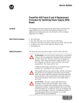
Fig. 1-1 AC Leakage Test
If the measured resistance is less than 1.0 megohm
or greater than 5.2 megohms, an abnormality exists
that must be corrected before the unit is returned
to the customer.
4. Leakage Current Hot Check (See Fig. 1-1) :
Warning : Do not use an isolation transformer
during this test. Use a leakage current tester or a
metering system that complies with American
National Standards Institute (ANSI C101.1,
Leakage Current for Appliances), and Underwriters
Laboratories (UL Publication UL1410, 59.7).
5. With the unit completely reassembled, plug the AC
line cord directly the power outlet. With the unitÕs
AC switch first in the ON position and then OFF,
measure the current between a known earth
ground (metal water pipe, conduit, etc.) and all
exposed metal parts, including : antennas, handle
brackets, metal cabinets, screwheads and control
shafts. The current measured should not exceed
0.5 milliamp. Reverse the power-plug prongs in the
AC outlet and repeat the test.
6. X-ray Limits :
The picture tube is designed to prohibit X-ray
emissions. To ensure continued X-ray protection,
replace the picture tube only with one that is the
same type as the original.
Samsung Electronics
7. Antenna Cold Check :
With the unitÕs AC plug disconnected from the
AC source, connect an electrical jumper across the
two AC prongs. Connect one lead of the ohmmeter
to an AC prong.
Connect the other lead to the coaxial connector.
8. High Voltage Limit :
High voltage must be measured each time
servicing is done on the B+, horizontal deflection
or high voltage circuits.
Heed the high voltage limits. These include the
X-ray protection Specifications Label, and the
Product Safety and X-ray Warning Note on the
service data schematic.
9. Some semiconductor (Òsolid stateÓ) devices are
easily damaged by static electricity.
Such components are called Electrostatically
Sensitive Devices (ESDs); examples include
integrated circuits and some field-effect transistors.
The following techniques will reduce the
occurrence of component damage caused by static
electricity.
10. Immediately before handling any semiconductor
components or assemblies, drain the electrostatic
charge from your body by touching a known
earth ground. Alternatively, wear a discharging
Wrist-strap device. (Be sure to remove it prior to
applying power--this is an electric shock
precaution.)
1-1
Precautions
11. High voltage is maintained within specified limits
by close-tolerance, safety-related components and
adjustments. If the high voltage exceeds the
specified limits, check each of the special
components.
12. Design Alteration Warning :
Never alter or add to the mechanical or electrical
design of this unit. Example : Do not add
auxiliary audio or video connectors.
Such alterations might create a safety hazard.
Also, any design changes or additions will void
the manufacturerÕs warranty.
13. Hot Chassis Warning :
Some TV receiver chassis are electrically
connected directly to one conductor of the AC
power cord. If an isolation transformer is not
used, these units may be safely serviced only if
the AC power plug is inserted so that the chassis
is connected to the ground side of the AC source.
To confirm that the AC power plug is inserted
correctly, do the following : Using an AC
voltmeter, measure the voltage between the
chassis and a known earth ground. If the reading
is greater than 1.0V, remove the AC power plug,
reverse its polarity and reinsert. Re-measure the
voltage between the chassis and ground.
14. Some TV chassis are designed to operate with 85
volts AC between chassis and ground, regardless
of the AC plug polarity. These units can be safely
serviced only if an isolation transformer inserted
between the receiver and the power source.
18. Picture Tube Implosion Warning :
The picture tube in this receiver employs
Òintegral implosionÓ protection. To ensure
continued implosion protection, make sure that
the replacement picture tube is the same as the
original.
19. Do not remove, install or handle the picture tube
without first putting on shatterproof goggles
equipped with side shields. Never handle the
picture tube by its neck. Some Òin-lineÓ picture
tubes are equipped with a permanently attached
deflection yoke; do not try to remove such
Òpermanently attachedÓ yokes from the picture
tube.
20. Product Safety Notice :
Some electrical and mechanical parts have special
safety-related characteristics which might not be
obvious from visual inspection. These safety
features and the protection they give might be
lost if the replacement component differs from the
original--even if the replacement is rated for
higher voltage, wattage, etc.
Components that are critical for safety are
indicated in the circuit diagram by shading,
(
or
).
Use replacement components that have the same
ratings, especially for flame resistance and
dielectric strength specifications. A replacement
part that does not have the same safety
characteristics as the original might create shock,
fire or other hazards.
15. Never defeat any of the B+ voltage interlocks.
Do not apply AC power to the unit (or any of its
assemblies) unless all solid-state heat sinks are
correctly installed.
16. Always connect a test instrumentÕs ground lead to
the instrument chassis ground before connecting
the positive lead; always remove the instrumentÕs
ground lead last.
17. Observe the original lead dress, especially near
the following areas : Antenna wiring, sharp
edges, and especially the AC and high voltage
power supplies. Always inspect for pinched, outof-place, or frayed wiring. Do not change the
spacing between components and the printed
circuit board. Check the AC power cord for
damage. Make sure that leads and components
do not touch thermally hot parts.
1-2
Samsung Electronics
2. Alignment and Adjustment
2-1 Reference
1) X-Point (Tracking center) adjustment, “Head switching adjustment” and “NVRAM option setting” can be adjusted with remote control.
2) When replacing the Micom (IC601) and NVRAM (IC605 ; EEPROM) be sure to adjust the “Head switching adjustment” and
“NVRAM option setting”.
3) When replacing the cylinder ass’y, be sure to adjust the “X-Point” and “Head switching adjustment”.
4) Among Samsung VCR remote control used for adjustment as a accessory, only the remote control that has figures buttons (0 ~ 9) is
available for all adjustment regardless of chassis.
5) How to adjustment.
- Press the “SW718 (TEST)” button on Main PCB to set the adjustment mode.
- If the corresponding adjustment button is pressed, the adjustment is performed automatically.
- If the adjustment is completed, be sure to turn the power off.
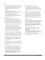
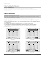
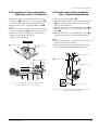
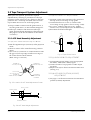
2-1-1 Location of adjustment button of remote control
VCR POWER
TV POWER
SLOW
TV
SHUTTLE
X-Point (Tracking Center) Adjustment
("5" Button)
VCR
V-LOCK
CLR/RST
DISP./
F.ADV
-/-INPUT
REPEAT
NVRAM Option Setting
("MENU" Button)
Head Switching Adjustment
("SPEED" Button)
VOL
INDEX
PROG/TRK
MENU
AU
DI
O
C
RE
D
EE
SP
OK
POWER
DISPLAY
CNT.RESET SPEED
IIP/S
REC
<This type of remote control can adjust.>
IPC
REPEAT
TRK
MENU
<This type of remote control can not adjust.>
Remote Control for adjustment is not supplied as a Service Jig.
Fig. 2-1
Samsung Electronics
2-1
Alignment and Adjustment
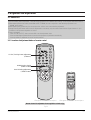
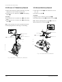
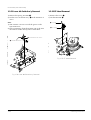
2-1-2 SW718 (TEST) location for adjustment mode setting
PRESS
Fig. 2-2 Main PCB (Top View)
2-2
Samsung Electronics
Alignment and Adjustment
2-2 Mechanical Adjustment
Note : Refer to the Mechanical Manual ÒDX-9R (AC68-00001A)Ó for the adjustment and confirmation of
assÕy full deck.
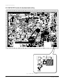
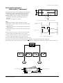
2-2-1 The number and position of test point
Test point :
TP601 (H’D S/W -Trigger)
TP301 (Video output)
TP602 (Control Pulse)
TP302 (Audio output)
TP303 (Envelope)
AUDIO OUTPUT
ENVELOPE
HEAD SWITCHING
Fig. 2-3 Location of Test point (Main PCB-Top View)
2-2-1 ACE Head Position (X-Point) Adjustment
(See the 2-2-1(d) ACE Head Position (X-Point) Adjustment
on page 2-2 of the Mechanical Manual)
1) Playback the alignment tape (Color bar).
2) Press the ÒSW718 (TEST)Ó button on Main PCB to
set the adjustment mode. (See Fig. 2-2)
3) Press the Ò5Ó button of remote control then
adjustment is operated automatically. (See Fig. 2-1)
Samsung Electronics
4) Connect the CH-1 probe to TP303 (Envelope) the
CH-2 probe to TP601 (HÕD switching pulse) and
then trigger to CH-1.
5) Insert the (-) driver into the X-Point adjustment
hole and adjust it so that envelope waveform is
maximum.
6) Turn the Power off.
2-3
Alignment and Adjustment
2-3 Head Switching Point Adjustment
1) Playback the alignment tape.
2) Press the ÒSW718 (TEST)Ó button on Main PCB to set the adjustment mode. (See Fig. 2-2)
3) Press the ÒSPEEDÓ button of remote control then adjustment is operated automatically. (See Fig. 2-1)
4) Turn the Power off.
2-4 NVRAM Option Setting
1) NVRAM Option is adjusted at production line basically.
2) In case Micom (IC601) and NVRAM (IC605 ; EEPROM) is replaced, be sure to set the corresponding option number of the repaired
model. (If the option is not set, the unit is not operated.)
1) Press the ÒSW718 (TEST)Ó button on Main PCB to set the adjustment mode. (See Fig. 2-2)
2) Press the ÒMENUÓ button on the remote control about 5 seconds then option setting display is appeared.
(See Fig. 2-4 and 2-5)
3) Select the option number (See Table 2-1 ; Page 2-5) of corresponding model with ÒFFÓ and ÒREWÓ button on
the remote control.
4) If selecting the option number is completed, press the ÒPLAYÓ button of remote control.
(If ÒPLAYÓ button is pressed, the selected number is changes reversed color. ; See Fig. 2-4 and 2-5)
5) Press the ÒOK (VCR)Ó, ÒMENU (VCP)Ó button of remote control again to store the option number.
(ÒPLEASE WAITÓ is displayed for a second as shown Fig. 2-6, 2-7 and this setting is completed.)
6) Turn the Power off.
** OPTION DIODE **
01
09
17
25
33
41
02
10
18
26
34
42
03
11
19
27
35
43
04
12
20
28
36
44
CNG :
05
13
21
29
37
45
06
14
22
30
38
46
07
15
23
31
39
47
** OPTION DIODE **
08
16
24
32
40
48
01
09
17
25
33
41
02
10
18
26
34
42
SAVE : OK
03 04 05 06 07
11 12 13 14 15
19 20 21 22 23
27 28 29 30 31
35 36 37 38 39
43 44 45 46 47
PLEASE WAIT
CNG :
SAVE : OK
Fig. 2-6 (VCR)
2-4
05
13
21
29
37
45
06
14
22
30
38
46
07
15
23
31
39
47
08
16
24
32
40
48
SAVE : MENU
Fig. 2-5 (VCP)
** OPTION DIODE **
02
10
18
26
34
42
04
12
20
28
36
44
CNG :
Fig. 2-4 (VCR)
01
09
17
25
33
41
03
11
19
27
35
43
** OPTION DIODE **
08
16
24
32
40
48
01
09
17
25
33
41
02
10
18
26
34
42
03 04 05 06 07 08
11 12 13 14 15 16
19 20 21 22 23 24
27 28 29 30 31 32
35 36 37 38 39 40
43 44 45 46 47 48
PLEASE WAIT
CNG :
SAVE : MENU
Fig. 2-7 (VCP)
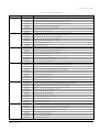
Samsung Electronics
Alignment and Adjustment
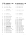
<Table 2-1 NVRAM Option Number>
COUNTRY
MODELS
France
SV-627F
SV-623F
SV-620F
SV-425F
SV-423F
SV-420F
SV-223F
SV-220F
SV-627B
SV-625B
SV-623B
SV-620B
SV-225B
SV-223B
SV-220B
SV-120W
SV-627X
SV-623X
SV-425X
SV-225X
SV-223X
SV-6233X
SV-2233X
SV-120W
SV-627X
SV-625X
SV-623X
SV-621X
SV-520X
SV-425X
SV-421X
SV-225X
SV-221X
SV-120W
SV-627X
SV-625X
SV-621X
SV-520X
SV-425X
SV-4215X
SV-4213X
SV-421X
SV-225X
SV-2215X
SV-2213X
SV-221X
SV-627X
SV-625X
SV-621X
SV-520X
SV-425X
SV-421X
SV-225X
SV-221X
U.K.
Germany
Spain
Italy
Portugal
Samsung Electronics
OPTION NUMBER
2, 4, 5, 6, 7, 8, 12, 13, 14, 15, 18, 19, 23, 24, 26, 29, 33, 36, 38, 41, 43, 44, 46
2, 5, 6, 8, 12, 13, 14, 15, 18, 19, 23, 26, 29, 35, 38, 44, 46
5, 8, 12, 13, 14, 15, 18, 19, 23, 26, 29, 34, 40, 46
2, 4, 5, 6, 7, 8, 12, 18, 19, 23, 24, 26, 29, 35, 38, 41, 43, 46
2, 5, 6, 8, 12, 18, 19, 23, 26, 29, 35, 38, 46
5, 8, 12, 18, 19, 23, 26, 29, 34, 40, 46
2, 5, 6, 18, 19, 23, 26, 29, 35, 38
5, 18, 19, 23, 26, 29, 34, 40
3, 4, 6, 7, 8, 10, 12, 13, 15, 16, 23, 24, 27, 33, 36, 41, 43, 46
3, 6, 7, 8, 10, 12, 13, 15, 23, 24, 27, 35, 37, 38, 41, 46
3, 7, 8, 10, 12, 13, 15, 24, 27, 35, 37, 38, 46
7, 8, 10. 12, 13, 15, 24, 27, 35, 37, 38, 46
3, 4, 6, 7, 8, 10, 23, 24, 27, 35, 37, 38, 43
3, 7, 8, 10, 24, 27, 35, 40
8, 10, 27, 35, 40
10, 16, 18, 34, 37, 42
2, 4, 5, 6, 7, 8, 9, 10, 12, 13, 14, 15, 18, 23, 24, 29, 32, 33, 36, 37, 38, 39, 40, 41, 43, 44
2, 5, 7, 8, 9, 10, 12, 13, 14, 18, 23, 24, 29, 32, 35, 37, 38
2, 5, 6, 7, 8, 12, 18, 23, 24, 29, 32, 35, 38
2, 4, 5, 7, 18, 23, 24, 29, 32, 35, 37, 38, 43
2, 7, 18, 24, 29, 32, 35, 40
2, 7, 8, 9, 10, 12, 13, 14, 18, 24, 29, 32, 35, 37, 39, 40
2, 7, 18, 24, 29, 32, 35, 37, 39, 40
9, 10, 16, 18, 29, 32, 34, 37, 42
2, 4, 5, 6, 7, 8, 9, 10, 12, 13, 14, 15, 18, 23, 24, 31, 33, 36, 37, 38, 39, 40, 41, 43, 44
2, 5, 6, 7, 8, 9, 10, 12, 13, 14, 15, 18, 23, 24, 31, 35, 38, 41, 44
2, 5, 6, 8, 9, 10, 12, 13, 14, 15, 18, 23, 31, 35, 37, 38, 39
5, 6, 8, 9, 10, 12, 13, 14, 15, 18, 23, 31, 35, 37, 38, 39
2, 5, 6, 7, 8, 9, 10, 12, 13, 18, 23, 24, 31, 35, 37, 38, 39
2, 5, 6, 7, 8, 12, 18, 23, 24, 31, 35, 38
5, 8, 12, 18, 23, 31, 35, 40
2, 5, 6, 7, 18, 23, 24, 31, 35, 38
5, 18, 23, 31, 35, 40
9, 10, 16, 18, 31, 34, 37, 42
2, 4, 5, 6, 7, 8, 9, 10, 12, 13, 14, 15, 18, 23, 24, 29, 31, 33, 36, 37, 38, 39, 40, 41, 43, 44
2, 5, 6, 7, 8, 9, 10, 12, 13, 14, 15, 18, 23, 24, 29, 31, 35, 38, 41, 44
5, 6, 8, 9, 10, 12, 13, 14, 15, 18, 23, 29, 31, 35, 37, 38, 39
2, 5, 6, 7, 8, 9, 10, 12, 13, 18, 23, 24, 29, 31, 35, 37, 38, 39
2, 5, 6, 7, 8, 12, 18, 23, 24, 29, 31, 35, 38
5, 8, 12, 18, 23, 29, 31, 35, 40
5, 8, 12, 18, 23, 29, 31, 35, 40
5, 8, 12, 18, 23, 29, 31, 35, 40
2, 5, 6, 7, 18, 23, 24, 29, 31, 35, 38
5, 18, 23, 29, 31, 35, 40
5, 18, 23, 29, 31, 35, 40
5, 18, 23, 29, 31, 35, 40
2, 5, 6, 7, 8, 9, 10, 12, 13, 14, 15, 18, 23, 33, 36, 37, 38, 39, 40, 41, 44, 48
2, 5, 6, 7, 8, 9, 10, 12, 13, 14, 15, 18, 23, 35, 38, 41, 44, 48
5, 6, 8, 9, 10, 12, 13, 14, 15, 18, 23, 35, 37, 38, 39, 48
2, 5, 6, 7, 8, 9, 10, 12, 13, 18, 23, 35, 37, 38, 39, 48
2, 5, 6, 7, 8, 12, 18, 23, 35, 38, 48
5, 8, 12, 18, 23, 35, 40, 48
2, 5, 6, 7, 18, 23, 35, 38, 48
5, 18, 23, 35, 40, 48
2-5
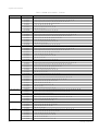
Alignment and Adjustment
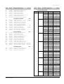
<Table 2-1 NVRAM Option Number> - Continued
COUNTRY
MODELS
Denmark
SV-627X
SV-625X
SV-621X
SV-425X
SV-421X
SV-225X
SV-220X
SV-2253X
SV-627X
SV-625X
SV-621X
SV-425X
SV-421X
SV-225X
SV-220X
SV-2253X
SV-627X
SV-625X
SV-621X
SV-425X
SV-421X
SV-225X
SV-220X
SV-2253X
SV-627X
SV-625X
SV-621X
SV-425X
SV-421X
SV-225X
SV-220X
SV-2253X
SV-627X
SV-625X
SV-621X
SV-425X
SV-421X
SV-225X
SV-220X
SV-2253X
SV-627F
SV-425F
SV-220F
SV-627X
SV-625X
SV-425X
SV-225X
SV-625X
SV-425X
SV-421X
SV-220X
SV-625X
SV-425X
SV-421X
SV-225X
SV-220X
SV-120W
Sweden/Finland
Norway
Netherlands
Belgium
Switzerland
Austria
Greece
Croatia
2-6
OPTION NUMBER
2, 5, 6, 7, 8, 9, 10, 12, 13, 14, 15, 18, 23, 24, 29, 30, 33, 36, 37, 38, 39, 40, 41, 44
2, 5, 6, 7, 8, 9, 10, 12, 13, 14, 15, 18, 23, 24, 29, 30, 35, 38, 41, 44
5, 6, 8, 9, 10, 12, 13, 14, 15, 18, 23, 29, 30, 35, 37, 38, 39
2, 5, 6, 7, 8, 12, 18, 23, 24, 29, 30, 35, 38
5, 8, 12, 18, 23, 29, 30, 35, 40
2, 5, 6, 7, 18, 23, 24, 29, 30, 35, 38
18, 29, 30, 35, 40,
2, 5, 6, 7, 18, 23, 24, 29, 30, 35, 39, 40
2, 5, 6, 7, 8, 9, 10, 12, 13, 14, 15, 18, 23, 24, 29, 30, 31, 33, 36, 37, 38, 39, 40, 41, 44
2, 5, 6, 7, 8, 9, 10, 12, 13, 14, 15, 18, 23, 24, 29, 30, 31, 35, 38, 41, 44
5, 6, 8, 9, 10, 12, 13, 14, 15, 18, 23, 29, 30, 31, 35, 37, 38, 39
2, 5, 6, 7, 8, 12, 18, 23, 24, 29, 30, 31, 35, 38
5, 8, 12, 18, 23, 29, 30, 31, 35, 40
2, 5, 6, 7, 18, 23, 24, 29, 30, 31, 35, 38
18, 29, 30, 31, 35, 40
2, 5, 6, 7, 18, 23, 24, 29, 30, 31, 35, 39, 40
2, 5, 6, 7, 8, 9, 10, 12, 13, 14, 15, 18, 23, 24, 30, 31, 33, 36, 37, 38, 39, 40, 41, 44
2, 5, 6, 7, 8, 9, 10, 12, 13, 14, 15, 18, 23, 24, 30, 31, 35, 38, 41, 44
5, 6, 8, 9, 10, 12, 13, 14, 15, 18, 23, 30, 31, 35, 37, 38, 39
2, 5, 6, 7, 8, 12, 18, 23, 24, 30, 31, 35, 38
5, 8, 12, 18, 23, 30, 31, 35, 40
2, 5, 6, 7, 18, 23, 24, 30, 31, 35, 38
18, 30, 31, 35, 40
2, 5, 6, 7, 18, 23, 24, 30, 31, 35, 39, 40
2, 5, 6, 7, 8, 9, 10, 12, 13, 14, 15, 18, 23, 24, 29, 30, 32, 33, 36, 37, 38, 39, 40, 41, 44
2, 5, 6, 7, 8, 9, 10, 12, 13, 14, 15, 18, 23, 24, 29, 30, 32, 35, 38, 41, 44
5, 6, 8, 9, 10, 12, 13, 14, 15, 18, 23, 29, 30, 32, 35, 37, 38, 39
2, 5, 6, 7, 8, 12, 18, 23, 24, 29, 30, 32, 35, 38
5, 8, 12, 18, 23, 29, 30, 32, 35, 40
2, 5, 6, 7, 18, 23, 24, 29, 30, 32, 35, 38
18, 29, 30, 32, 35, 40
2, 5, 6, 7, 18, 23, 24, 29, 30, 32, 35, 39, 40
2, 5, 6, 7, 8, 9, 10, 12, 13, 14, 15, 18, 23, 24, 30, 33, 36, 37, 38, 39, 40, 41, 44
2, 5, 6, 7, 8, 9, 10, 12, 13, 14, 15, 18, 23, 24, 30, 35, 38, 41, 44
5, 6, 8, 9, 10, 12, 13, 14, 15, 18, 23, 30, 35, 37, 38, 39
2, 5, 6, 7, 8, 12, 18, 23, 24, 30, 35, 38
5, 8, 12, 18, 23, 30, 35, 40
2, 5, 6, 7, 18, 23, 24, 30, 35, 38
18, 30, 35, 40
2, 5, 6, 7, 18, 23, 24, 30, 35, 39, 40
2, 4, 5, 6, 7, 8, 12, 13, 14, 15, 18, 19, 23, 24, 26, 31, 32, 33, 36, 38, 41, 43, 44
2, 4, 5, 6, 7, 8, 12, 18, 19, 23, 24, 26, 31, 32, 35, 38, 41, 43
5, 18, 19, 23, 26, 31, 32, 35, 40
2, 5, 6, 7, 8, 9, 10, 12, 13, 14, 15, 18, 23, 24, 32, 33, 36, 37, 38, 39, 40, 41, 44
2, 5, 6, 7, 8, 9, 10, 12, 13, 14, 15, 18, 23, 24, 32, 35, 38, 41, 44
2, 5, 6, 7, 8, 12, 18, 23, 24, 32, 35, 38
2, 5, 6, 7, 18, 23, 24, 32, 35, 38
2, 5, 6, 7, 8, 9, 10, 12, 13, 14, 15, 18, 23, 32, 35, 38, 41, 44, 48
2, 5, 6, 7, 8, 12, 18, 23, 32, 35, 38, 48
5, 8, 12, 18, 23, 32, 35, 40, 48
18, 32, 35, 40, 48
2, 5, 6, 7, 8, 9, 10, 12, 13, 14, 15, 18, 23, 30, 32, 35, 38, 41, 44, 48
2, 5, 6, 7, 8, 12, 18, 23, 30, 32, 35, 38, 48
5, 8, 12, 18, 23, 30, 32, 35, 40, 48
2, 5, 6, 7, 18, 23, 30, 32, 35, 38, 48
18, 30, 32, 35, 40, 48
9, 10, 16, 18, 30, 32, 34, 37, 42, 48
Samsung Electronics
Alignment and Adjustment
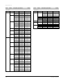
<Table 2-1 NVRAM Option Number> - Continued
COUNTRY
MODELS
Slovenia
SV-625X
SV-425X
SV-421X
SV-225X
SV-220X
SV-625G
SV-620G
SV-425G
SV-420G
SV-225G
SV-220G
SV-4253G
SV-4203G
SV-2203G
SV-625G
SV-620G
SV-425G
SV-420G
SV-225G
SV-220G
SV-625G
SV-620G
SV-425G
SV-420G
SV-225G
SV-220G
SV-625G
SV-620G
SV-425G
SV-420G
SV-225G
SV-220G
SV-4253G
SV-4203G
SV-2203G
SV-C35K
SV-C620K
SV-C80K
SV-C35K
SV-C30K
SV-C10K
SV-C35K
SV-C35K
SV-C35K
SV-620I
SV-C35K
SVR-629
SVR-623
SV-627B
SV-620B
SV-620X
SV-620G
SV-600G
SV-620G
Hungary
Romania
Czecho
Poland
Malaysia
Algeciras
Mauritania
Morocco
Algeria
South Africa
C.I.S.
Australia
New Zealand
U.A.E.
Iran
Saudi Arabia
Samsung Electronics
OPTION NUMBER
2, 5, 6, 7, 8, 9, 10, 12, 13, 14, 15, 18, 23, 30, 31, 35, 38, 41, 44, 48
2, 5, 6, 7, 8, 12, 18, 23, 30, 31, 35, 38, 48
5, 8, 12, 18, 23, 30, 31, 35, 40, 48
2, 5, 6, 7, 18, 23, 30, 31, 35, 38, 48
18, 30, 31, 35, 40, 48
2, 5, 6, 7, 8, 11, 12, 13, 14, 15, 18, 23, 25, 31, 32, 35, 38, 41, 44, 48
8, 11, 12, 13, 14, 15, 18, 25, 31, 32, 35, 40, 48
2, 5, 6, 7, 8, 11, 12, 18, 23, 25, 31, 32, 35, 38, 41, 48
8, 11, 12, 18, 25, 31, 32, 35, 40, 48
2, 5, 6, 7, 11, 18, 23, 25, 31, 32, 35, 38, 48
11, 18, 25, 31, 32, 35, 40, 48
2, 5, 6, 7, 8, 11, 12, 18, 23, 25, 31, 32, 35, 39, 40, 41, 48
8, 11, 12, 18, 25, 31, 32, 35, 37, 39, 40, 48
11, 18, 25, 31, 32, 35, 37, 39, 40, 48
2, 5, 6, 7, 8, 11, 12, 13, 14, 15, 18, 23, 25, 29, 32, 35, 38, 41, 44, 48
8, 11, 12, 13, 14, 15, 18, 25, 29, 32, 35, 40, 48
2, 5, 6, 7, 8, 11, 12, 18, 23, 25, 29, 32, 35, 38, 41, 48
8, 11, 12, 18, 25, 29, 32, 35, 40, 48
2, 5, 6, 7, 11, 18, 23, 25, 29, 32, 35, 38, 48
11, 18, 25, 29, 32, 35, 40, 48
2, 5, 6, 7, 8, 11, 12, 13, 14, 15, 18, 23, 25, 30, 35, 38, 41, 44, 48
8, 11, 12, 13, 14, 15, 18, 25, 30, 35, 40, 48
2, 5, 6, 7, 8, 11, 12, 18, 23, 25, 30, 35, 38, 41, 48
8, 11, 12, 18, 25, 30, 35, 40, 48
2, 5, 6, 7, 11, 18, 23, 25, 30, 35, 38, 48
11, 18, 25, 30, 35, 40, 48
2, 5, 6, 7, 8, 11, 12, 13, 14, 15, 18, 23, 25, 31, 35, 38, 41, 44, 48
8, 11, 12, 13, 14, 15, 18, 25, 31, 35, 40, 48
2, 5, 6, 7, 8, 11, 12, 18, 23, 25, 31, 35, 38, 41, 48
8, 11, 12, 18, 25, 31, 35, 40, 48
2, 5, 6, 7, 11, 18, 23, 25, 31, 35, 38, 48
11, 18, 25, 31, 35, 40, 48
2, 5, 6, 7, 8, 11, 12, 18, 23, 25, 31, 35, 39, 40, 41, 48
8, 11, 12, 18, 25, 31, 35, 37, 39, 40, 48
11, 18, 25, 31, 35, 37, 39, 40, 48
5, 6, 9, 10, 11, 18, 19, 23, 25, 26, 29, 31, 32, 35, 39, 40
5, 6, 8, 9, 10, 11, 12, 13, 14, 15, 18, 19, 23, 25, 26, 29, 31, 32, 36, 37, 38, 39, 40, 41, 44, 46
5, 6, 8, 9, 10, 11, 12, 18, 19, 23, 25, 26, 29, 31, 32, 35, 41, 45, 46
5, 6, 9, 10, 11, 18, 19, 23, 25, 26, 29, 31, 32, 35, 39, 40
5, 6, 9, 10, 11, 18, 19, 23, 25, 26, 29, 31, 32, 35, 38, 40, 45
9, 10, 11, 17, 18, 19, 29, 31, 32, 34, 37, 39, 40, 42
6, 8, 11, 12, 13, 14, 15, 17, 18, 20, 25, 26, 30, 31, 32, 36, 37, 38, 39, 40, 41, 46, 48
5, 6, 9, 10, 11, 18, 19, 23, 25, 26, 29, 31, 32, 35, 39, 40
5, 6, 9, 10, 11, 18, 19, 23, 25, 26, 29, 31, 32, 35, 39, 40
5, 6, 9, 10, 11, 18, 19, 23, 25, 26, 29, 31, 32, 35, 39, 40, 42
6, 8, 9, 11, 12, 13, 14, 15, 17, 18, 25, 26, 29, 31, 32, 35, 37, 38, 39, 40, 41, 44, 46
5, 6, 9, 10, 11, 18, 19, 23, 25, 26, 29, 31, 32, 35, 39, 40, 42
2, 6, 8, 11, 12, 13, 18, 19, 20, 21, 25, 30, 31, 32, 33, 36, 37, 38, 39, 40, 41, 44, 46
6, 8, 11, 12, 13, 17, 18, 25, 30, 31, 32, 35, 41, 44, 45, 46
1, 6, 8, 9, 12, 13, 14, 17, 18, 20, 21, 25, 27, 29, 31, 32, 36, 37, 38, 39, 40, 41, 44, 46
1, 6, 8, 9, 12, 13, 14, 17, 18, 25, 27, 29, 31, 32, 35, 38, 41, 44, 46
1, 6, 8, 12, 13, 14, 15, 17, 18, 25, 26, 29, 31, 32, 35, 38, 41, 44, 46
6, 8, 11, 12, 13, 14, 15, 17, 18, 20, 25, 26, 30, 31, 32, 36, 37, 38, 39, 40, 41, 42, 44, 46, 48
6, 8, 11, 12, 13, 14, 15, 17, 18, 20, 25, 26, 29, 36, 37, 38, 39, 40, 41, 42, 46, 48
2-7
Alignment and Adjustment
MEMO
2-8
Samsung Electronics
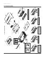
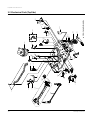
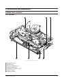
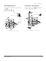
3. Exploded View and Parts List
Page
3-1 Cabinet Assembly - - - - - - - - - - - - - - - - - - - - - - - - - - - - - - - - - - - - - - - - - 3-2
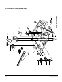
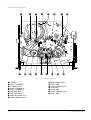
3-2 Mechanical Parts (Top Side) - - - - - - - - - - - - - - - - - - - - - - - - - - - - - - - - -
3-6
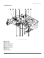
3-3 Mechanical Parts (Bottom Side) - - - - - - - - - - - - - - - - - - - - - - - - - - - - - - - 3-8
Samsung Electronics
3-1
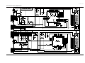
3-2
21
55
157
22
1
SVR-623/SV-C80K
51
21
56
F-A/V JACK PCB (S.N.A.)
SHUTTLE PCB (S.N.A.)
CN703S (5P)
SV-625X/623X/620X/425X/225X
SV-627F/623F/425F/423F/223F
SV-625B/623B/620B/225B
SV-625G/425G/225G/C10K
157
CN703S (8P)
SRC PCB (S.N.A.)
BRACKET-FRAME
(S.N.A.)
157
FULL DECK (S.N.A.)
153
22
1
157
1
S601A
22
LD601A
SV-621X/520X/421X/4215X/4213X
SV-223X/221X/2215X/2213X/220X
SV-620F/420F/220F/223B/220B
SV-620G/420G/220G
21
VFD/LED PCB (S.N.A.)
A2/NICAM PCB-OPTION
(S.N.A.)
1
S602A
TM401B
S.N.A. : Service Not Available
101
21
31
200
156
52
21
155
52
22
1
51
SV-C30K
21
22
22
158
SV-627X/627B/620G/600G/620I/C620K/SVR-629
SV-6233X/2253X/2233X/120W
SV-4253G/4203G/2203G/C35K
102
MAIN PCB (S.N.A.)
CN602S
CN3A1S
156
1
1
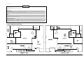
Exploded View and Parts List
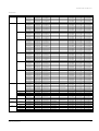
3-1 Cabinet Assembly
Samsung Electronics
Exploded View and Parts List
Loc. No
1
21
22
31
51
52
55
56
101
102
153
155
156
157
200
CN3A1S
CN602S
CN703S
LD601A
S601A
S602A
TM401B
Parts No.
Refer to table below
Refer to table below
AC61-62032A
Refer to table below
Refer to table below
62664-0021-00
AC61-30164D
AC61-30164C
Refer to table below
AC63-30519A
AC60-12126A
AC60-12134A
AC60-00001A
AC60-10063A
Refer to table below
3809-001110
3809-001112
3809-001112
3809-001132
AC61-21009A
AC61-21008A
AC61-21008A
Refer to table below
Description ; Specification
Remark
ASSY-PANEL FRONT;HIPS 94HB
DOOR-CASSETTE
SPRING-MASK;X-9,-,SUS,-,4.4,-,SV-C130
DOOR FRONT-ASSY
KNOB-SHUTTLE ASSY;ABS94,HB,B
ASSY-DAMPER
LOCKER-CODO ASSY L;-,LUCEL+SECC+SUS,-,-,
LOCKER-CODO ASSY R;-,LUCEL+SECC+SUS,-,BL
CABINET-TOP;X-9,SECC,PCM,0.5,360*208*41,
COVER-BOTTOM;SV-C833,SPTE,-,T0.3,-,-,-,X
SCREW-BH;-,BH,-,4*12,FE,FZY,-,-,SCREW-TAP BH;-,BH,-,2-4X16,-,FE
SCREW-TAP BH;-,BH,-,2-4X12,-,FE
SCREW-TAPTITE;BH,+,-,M3,L12,ZPC3,SWRCH18
POWER CORD;KKP-419C,H03VVH2-F,VDE/KEMA-K
CABLE-FLAT;30V,80C,150mm,7P,1.25mm,UL289
CABLE-FLAT;30V,80C,130mm,5P,1.25mm,UL289
CABLE-FLAT;30V,80C,130mm,5P,1.25mm,UL289
CABLE-FLAT;30V,80C,130mm,8P,1.25mm,UL2896
HOLDER-LED;-,POM(M90-44),-,BLK,-,X-9
HOLDER-SENSOR;-,POM(M90-44),-,BLK,-,X-9
HOLDER-SENSOR;-,POM(M90-44),-,BLK,-,X-9
CONNECTOR BOARD-ASSY;HIPS94
(OPTIONAL)
(OPTIONAL)
5P (OPTIONAL)
8P (OPTIONAL)
REGION
COUNTRY
MODELS
1
21
31
51
101
TM401B
200
Europe
France
SV-627F
SV-623F
SV-620F
SV-425F
SV-423F
SV-420F
SV-223F
SV-220F
SV-627B
SV-625B
SV-623B
SV-620B
SV-225B
SV-223B
SV-220B
SV-120W
SV-627X
SV-623X
SV-425X
SV-225X
SV-223X
SV-6233X
SV-2233X
SV-120W
SV-627X
SV-625X
SV-623X
SV-621X
SV-520X
SV-425X
SV-421X
SV-225X
SV-221X
SV-120W
AC97-00011A
AC97-00010A
AC97-00013A
AC97-00014A
AC97-00015A
AC97-00016A
AC97-00012A
AC97-00017A
AC97-00243A
AC97-00018A
AC97-00018B
AC97-00019A
AC97-00020A
AC97-00021A
AC97-00143A
AC97-00213G
AC97-00244A
AC97-00022A
AC97-00023A
AC97-00024A
AC97-00026A
AC97-00213A
AC97-00213B
AC97-00213G
AC97-00244A
AC97-00144A
AC97-00144C
AC97-00027A
AC97-00145A
AC97-00023A
AC97-00028A
AC97-00025A
AC97-00029A
AC97-00213G
AC64-00096A
AC64-00103G
AC64-00103H
AC64-00096B
AC64-00054J
AC64-00054K
AC64-00054L
AC64-00054M
AC64-52158T
AC64-00096C
AC64-00054N
AC64-00054P
AC64-00096D
AC64-00054Q
AC64-00054R
AC64-52172K
AC64-52158U
AC64-00096E
AC64-00096F
AC64-00096G
AC64-00054S
AC64-52172F
AC64-52172E
AC64-52172K
AC64-52158U
AC64-00096H
AC64-00054T
AC64-00054U
AC64-00054V
AC64-00096F
AC64-00054W
AC64-00096K
AC64-00054X
AC64-52172K
AC64-00072A
AC64-00072F
AC64-00072F
-
-
AC64-30899E
AC64-30899E
AC64-30899E
AC64-30899E
AC64-30899E
AC64-30899E
AC64-30899E
AC64-30899E
AC64-30899E
AC64-30899E
AC64-30899E
AC64-30899E
AC64-30899A
AC64-30899A
AC64-30899A
AC64-30899A
AC64-30899E
AC64-30899A
AC64-30899A
AC64-30899A
AC64-30899A
AC64-30899A
AC64-30899A
AC64-30899A
AC64-30899E
AC64-30899E
AC64-30899E
AC64-30899E
AC64-30899E
AC64-30899A
AC64-30899A
AC64-30899A
AC64-30899A
AC64-30899A
AC61-11061H
AC61-11061H
AC61-11061H
AC61-11061N
AC61-11061N
AC61-11061N
AC61-11061N
AC61-11061N
AC61-11061K
AC61-11061K
AC61-11061L
AC61-11061L
AC61-11061Q
AC61-11061R
AC61-11061R
AC61-11061S
AC61-11061J
AC61-11061J
AC61-11061P
AC61-11061P
AC61-11061R
AC61-11061L
AC61-11061R
AC61-11061S
AC61-11061J
AC61-11061J
AC61-11061J
AC61-11061J
AC61-11061J
AC61-11061P
AC61-11061P
AC61-11061P
AC61-11061P
AC61-11061S
AC39-10019A
AC39-10019A
AC39-10019A
AC39-10019A
AC39-10019A
AC39-10019A
AC39-10019A
AC39-10019A
AC39-10022K
AC39-10022K
AC39-10022K
AC39-10022K
AC39-10022K
AC39-10022K
AC39-10022K
AC39-10022K
AC39-10019A
AC39-10019A
AC39-10019A
AC39-10019A
AC39-10019A
AC39-10019A
AC39-10019A
AC39-10019A
AC39-10019A
AC39-10019A
AC39-10019A
AC39-10019A
AC39-10019A
AC39-10019A
AC39-10019A
AC39-10019A
AC39-10019A
AC39-10019A
U.K.
Germany
Spain
Samsung Electronics
3-3
Exploded View and Parts List
<Continued>
REGION
COUNTRY
MODELS
1
21
31
51
101
TM401B
200
Europe
Italy
SV-627X
SV-625X
SV-621X
SV-520X
SV-425X
SV-4215X
SV-4213X
SV-421X
SV-225X
SV-2215X
SV-2213X
SV-221X
SV-627X
SV-625X
SV-621X
SV-520X
SV-425X
SV-421X
SV-225X
SV-221X
SV-627X
SV-625X
SV-621X
SV-425X
SV-421X
SV-225X
SV-220X
SV-2253X
SV-627X
SV-625X
SV-621X
SV-425X
SV-421X
SV-225X
SV-220X
SV-2253X
SV-627X
SV-625X
SV-621X
SV-425X
SV-421X
SV-225X
SV-220X
SV-2253X
SV-627X
SV-625X
SV-621X
SV-425X
SV-421X
SV-225X
SV-220X
SV-2253X
SV-627X
SV-625X
SV-621X
SV-425X
SV-421X
SV-225X
SV-220X
SV-2253X
SV-627F
SV-425F
SV-220F
SV-627X
SV-625X
SV-425X
SV-225X
AC97-00244A
AC97-00144B
AC97-00027B
AC97-00145B
AC97-00023A
AC97-00146A
AC97-00147A
AC97-00028A
AC97-00025A
AC97-00148A
AC97-00148B
AC97-00029A
AC97-00245A
AC97-00144B
AC97-00027B
AC97-00145B
AC97-00023A
AC97-00028A
AC97-00025A
AC97-00029A
AC97-00245A
AC97-00144B
AC97-00027B
AC97-00023A
AC97-00028A
AC97-00025A
AC97-00030A
AC98-11258P
AC97-00245A
AC97-00144B
AC97-00027B
AC97-00023A
AC97-00028A
AC97-00025A
AC97-00030A
AC97-00213C
AC97-00245A
AC97-00144B
AC97-00027B
AC97-00023A
AC97-00028A
AC97-00025A
AC97-00030A
AC98-11258P
AC97-00245A
AC97-00144B
AC97-00027B
AC97-00023A
AC97-00028A
AC97-00025A
AC97-00030A
AC98-11258P
AC97-00245A
AC97-00144B
AC97-00027B
AC97-00023A
AC97-00028A
AC97-00025A
AC97-00030A
AC98-11258P
AC97-00150A
AC97-00151A
AC97-00152A
AC97-00244A
AC97-00144B
AC97-00023A
AC97-00025A
AC64-52158U
AC64-00096L
AC64-00054Y
AC64-00054Z
AC64-00096F
AC64-00103A
AC64-00103B
AC64-00054W
AC64-00096K
AC64-00103C
AC64-00103D
AC64-00054X
AC64-52158U
AC64-00096L
AC64-00054Y
AC64-00054Z
AC64-00096F
AC64-00054W
AC64-00096K
AC64-00054X
AC64-52158U
AC64-00096L
AC64-00054Y
AC64-00096F
AC64-00054W
AC64-00096K
AC64-00103E
AC64-52169C
AC64-52158U
AC64-00096L
AC64-00054Y
AC64-00096F
AC64-00054W
AC64-00096K
AC64-00103E
AC64-52169C
AC64-52158U
AC64-00096L
AC64-00054Y
AC64-00096F
AC64-00054W
AC64-00096K
AC64-00103E
AC64-52169C
AC64-52158U
AC64-00096L
AC64-00054Y
AC64-00096F
AC64-00054W
AC64-00096K
AC64-00103E
AC64-52169C
AC64-52158U
AC64-00096L
AC64-00054Y
AC64-00096F
AC64-00054W
AC64-00096K
AC64-00103E
AC64-52169C
AC64-00096M
AC64-00096N
AC64-00103F
AC64-52158U
AC64-00096L
AC64-00096F
AC64-00096K
AC64-00072F
AC64-00072B
AC64-00072B
AC64-00072B
AC64-00072B
AC64-00072B
AC64-00072B
-
-
AC64-30899E
AC64-30899A
AC64-30899A
AC64-30899A
AC64-30899A
AC64-30899E
AC64-30899E
AC64-30899A
AC64-30899A
AC64-30899E
AC64-30899E
AC64-30899A
AC64-30899E
AC64-30899A
AC64-30899A
AC64-30899A
AC64-30899A
AC64-30899A
AC64-30899A
AC64-30899A
AC64-30899E
AC64-30899A
AC64-30899A
AC64-30899A
AC64-30899A
AC64-30899A
AC64-30899A
AC64-30899A
AC64-30899E
AC64-30899A
AC64-30899A
AC64-30899A
AC64-30899A
AC64-30899A
AC64-30899A
AC64-30899A
AC64-30899E
AC64-30899A
AC64-30899A
AC64-30899A
AC64-30899A
AC64-30899A
AC64-30899A
AC64-30899A
AC64-30899E
AC64-30899A
AC64-30899A
AC64-30899A
AC64-30899A
AC64-30899A
AC64-30899A
AC64-30899A
AC64-30899E
AC64-30899A
AC64-30899A
AC64-30899A
AC64-30899A
AC64-30899A
AC64-30899A
AC64-30899A
AC64-30899A
AC64-30899A
AC64-30899A
AC64-30899E
AC64-30899A
AC64-30899A
AC64-30899A
AC61-11061J
AC61-11061J
AC61-11061J
AC61-11061J
AC61-11061P
AC61-11061P
AC61-11061P
AC61-11061P
AC61-11061P
AC61-11061P
AC61-11061P
AC61-11061P
AC61-11061J
AC61-11061J
AC61-11061J
AC61-11061J
AC61-11061P
AC61-11061P
AC61-11061P
AC61-11061P
AC61-11061J
AC61-11061J
AC61-11061J
AC61-11061P
AC61-11061P
AC61-11061P
AC61-11061R
AC61-11061P
AC61-11061J
AC61-11061J
AC61-11061J
AC61-11061P
AC61-11061P
AC61-11061P
AC61-11061R
AC61-11061P
AC61-11061J
AC61-11061J
AC61-11061J
AC61-11061P
AC61-11061P
AC61-11061P
AC61-11061R
AC61-11061P
AC61-11061J
AC61-11061J
AC61-11061J
AC61-11061P
AC61-11061P
AC61-11061P
AC61-11061R
AC61-11061P
AC61-11061J
AC61-11061J
AC61-11061J
AC61-11061P
AC61-11061P
AC61-11061P
AC61-11061R
AC61-11061P
AC61-11061H
AC61-11061N
AC61-11061N
AC61-11061J
AC61-11061J
AC61-11061P
AC61-11061P
AC39-10019A
AC39-10019A
AC39-10019A
AC39-10019A
AC39-10019A
AC39-10019A
AC39-10019A
AC39-10019A
AC39-10019A
AC39-10019A
AC39-10019A
AC39-10019A
AC39-10019A
AC39-10019A
AC39-10019A
AC39-10019A
AC39-10019A
AC39-10019A
AC39-10019A
AC39-10019A
AC39-10019A
AC39-10019A
AC39-10019A
AC39-10019A
AC39-10019A
AC39-10019A
AC39-10019A
AC39-10019A
AC39-10019A
AC39-10019A
AC39-10019A
AC39-10019A
AC39-10019A
AC39-10019A
AC39-10019A
AC39-10019A
AC39-10019A
AC39-10019A
AC39-10019A
AC39-10019A
AC39-10019A
AC39-10019A
AC39-10019A
AC39-10019A
AC39-10019A
AC39-10019A
AC39-10019A
AC39-10019A
AC39-10019A
AC39-10019A
AC39-10019A
AC39-10019A
AC39-10019A
AC39-10019A
AC39-10019A
AC39-10019A
AC39-10019A
AC39-10019A
AC39-10019A
AC39-10019A
AC39-10019A
AC39-10019A
AC39-10019A
AC39-10019A
AC39-10019A
AC39-10019A
AC39-10019A
Portugal
Denmark
Sweden/Finland
Norway
Netherlands
Belgium
Switzerland
Austria
3-4
AC64-00072F
-
Samsung Electronics
Exploded View and Parts List
<Continued>
REGION
COUNTRY
MODELS
1
21
31
51
101
TM401B
200
Europe
Greece
Middle Europe
Croatia
SV-625X
SV-425X
SV-421X
SV-220X
SV-625X
SV-425X
SV-421X
SV-225X
SV-220X
SV-120W
SV-625X
SV-425X
SV-421X
SV-225X
SV-220X
SV-625G
SV-620G
SV-425G
SV-420G
SV-225G
SV-220G
SV-4253G
SV-4203G
SV-2203G
SV-625G
SV-620G
SV-425G
SV-420G
SV-225G
SV-220G
SV-625G
SV-620G
SV-425G
SV-420G
SV-225G
SV-220G
SV-625G
SV-620G
SV-425G
SV-420G
SV-225G
SV-220G
SV-4253G
SV-4203G
SV-2203G
SV-C620K
SV-C80K
SV-C35K
SV-C30K
SV-C10K
SV-C35K
SV-C35K
SV-C35K
SV-620I
SV-C35K
SVR-629
SVR-623
SV-627B
SV-620B
SV-620X
SV-620G
SV-600G
SV-620G
SV-C35K
AC97-00144B
AC97-00023A
AC97-00028A
AC97-00030A
AC97-00144B
AC97-00023A
AC97-00028A
AC97-00025A
AC97-00030A
AC97-00213G
AC97-00144B
AC97-00023A
AC97-00028A
AC97-00025A
AC97-00030A
AC97-00153A
AC97-00154A
AC97-00155A
AC97-00156A
AC97-00157A
AC97-00158A
AC97-00213D
AC97-00213E
AC97-00213G
AC97-00153A
AC97-00154A
AC97-00155A
AC97-00156A
AC97-00157A
AC97-00158A
AC97-00153A
AC97-00154A
AC97-00155A
AC97-00156A
AC97-00157A
AC97-00158A
AC97-00153A
AC97-00154A
AC97-00155A
AC97-00156A
AC97-00157A
AC97-00158A
AC98-11258Q
AC98-11259G
AC98-11259H
AC97-00342A
AC97-00157F
AC97-00098A
AC97-00098B
AC97-00098D
AC97-00098A
AC97-00098A
AC97-00098A
AC97-00247A
AC97-00098A
AC97-00248A
AC97-00331A
AC97-00249A
AC97-00157G
AC97-00157D
AC97-00246A
AC97-00326A
AC97-00246A
AC97-00098A
AC64-00096L
AC64-00096F
AC64-00054W
AC64-00103E
AC64-00096L
AC64-00096F
AC64-00054W
AC64-00096K
AC64-00103E
AC64-52172K
AC64-00096L
AC64-00096F
AC64-00054W
AC64-00096K
AC64-00103E
AC64-00096P
AC64-00103J
AC64-00096Q
AC64-00103K
AC64-00096R
AC64-00103L
AC64-52172D
AC64-52172H
AC64-52172G
AC64-00096P
AC64-00103J
AC64-00096Q
AC64-00103K
AC64-00096R
AC64-00103L
AC64-00096P
AC64-00103J
AC64-00096Q
AC64-00103K
AC64-00096R
AC64-00103L
AC64-00096P
AC64-00103J
AC64-00096Q
AC64-00103K
AC64-00096R
AC64-00103L
AC64-52172D
AC64-52172H
AC64-52172G
AC64-52164C
AC64-00054F
AC64-52172J
AC64-52172R
AC64-52172T
AC64-52172J
AC64-52172J
AC64-52172J
AC64-52158W
AC64-52172J
AC64-52158X
AC64-00096S
AC64-52158Y
AC64-00054G
AC64-00103M
AC64-52158V
AC64-52158Z
AC64-52158V
AC64-52172J
AC64-00072J
AC64-00072G
AC64-00072D
AC64-00072E
AC64-00072C
AC64-00072H
AC64-00072C
-
AC97-00216B
AC97-00216B
AC97-00216D
-
AC64-30899A
AC64-30899A
AC64-30899A
AC64-30899A
AC64-30899A
AC64-30899A
AC64-30899A
AC64-30899A
AC64-30899A
AC64-30899A
AC64-30899A
AC64-30899A
AC64-30899A
AC64-30899A
AC64-30899A
AC64-30899A
AC64-30899A
AC64-30899A
AC64-30899A
AC64-30899A
AC64-30899A
AC64-30899A
AC64-30899A
AC64-30899A
AC64-30899A
AC64-30899A
AC64-30899A
AC64-30899A
AC64-30899A
AC64-30899A
AC64-30899A
AC64-30899A
AC64-30899A
AC64-30899A
AC64-30899A
AC64-30899A
AC64-30899A
AC64-30899A
AC64-30899A
AC64-30899A
AC64-30899A
AC64-30899A
AC64-30899A
AC64-30899A
AC64-30899A
AC64-30899E
AC64-30899E
AC64-30899E
AC64-30899E
AC64-30899E
AC64-30899E
AC64-30899A
AC64-30899E
AC64-30899E
AC64-30899E
AC64-30899E
AC64-30899A
AC64-30899E
AC64-30899A
AC64-30899A
AC64-30899E
AC64-30899E
AC64-30899E
AC64-30899E
AC61-11061J
AC61-11061P
AC61-11061P
AC61-11061R
AC61-11061J
AC61-11061P
AC61-11061P
AC61-11061P
AC61-11061R
AC61-11061S
AC61-11061J
AC61-11061P
AC61-11061P
AC61-11061P
AC61-11061R
AC61-11061J
AC61-11061L
AC61-11061P
AC61-11061R
AC61-11061P
AC61-11061R
AC61-11061P
AC61-11061R
AC61-11061R
AC61-11061J
AC61-11061L
AC61-11061P
AC61-11061R
AC61-11061P
AC61-11061R
AC61-11061J
AC61-11061L
AC61-11061P
AC61-11061R
AC61-11061P
AC61-11061R
AC61-11061J
AC61-11061L
AC61-11061P
AC61-11061R
AC61-11061P
AC61-11061R
AC61-11061P
AC61-11061R
AC61-11061R
AC61-11061J
AC61-11061P
AC61-11061P
AC61-11061P
AC61-11061S
AC61-11061P
AC61-11061P
AC61-11061P
AC61-11061M
AC61-11061P
AC61-11061L
AC61-11061M
AC61-11061M
AC61-11061M
AC61-11061M
AC61-11061M
AC61-11061M
AC61-11061M
AC61-11061P
AC39-10019A
AC39-10019A
AC39-10019A
AC39-10019A
AC39-10019A
AC39-10019A
AC39-10019A
AC39-10019A
AC39-10019A
AC39-10019A
AC39-10019A
AC39-10019A
AC39-10019A
AC39-10019A
AC39-10019A
AC39-10019A
AC39-10019A
AC39-10019A
AC39-10019A
AC39-10019A
AC39-10019A
AC39-10019A
AC39-10019A
AC39-10019A
AC39-10019A
AC39-10019A
AC39-10019A
AC39-10019A
AC39-10019A
AC39-10019A
AC39-10019A
AC39-10019A
AC39-10019A
AC39-10019A
AC39-10019A
AC39-10019A
AC39-10019A
AC39-10019A
AC39-10019A
AC39-10019A
AC39-10019A
AC39-10019A
AC39-10019A
AC39-10019A
AC39-10019A
AC39-10019A
AC39-10019A
AC39-10019A
AC39-10019A
AC39-10019A
AC39-10019A
AC39-10019A
AC39-10019A
AC39-10019A
AC39-10019A
AC39-10019A
AC39-10019A
AC39-10015A
AC39-10015A
AC39-10015A
AC39-10019A
AC39-10019A
AC39-10019A
AC39-10019A
Slovenia
Hungary
Romania
Czecho
Poland
Africa
Algeciras
Mauritania
Morocco
Algeria
South Africa
C.I.S.
C.I.S.
Oceania
Australia
Asia
New Zealand
U.A.E.
Iran
Saudi Arabia
Malaysia
Samsung Electronics
3-5
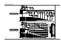
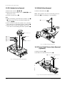
3-6
K530
K490
K248
K250
S.N.A.
K188
K182
K502
K110
K330
K350
K240
K140
K340
G530
G532
G546
B473
S.N.A.
S.N.A.
G420
B448
G450
S.N.A.
G001
G510
G480
S.N.A.
B452
B410
K546
S.N.A.
G555
S.N.A. : Service Not Available
B440
B444
B446
G527
G520
G680
Exploded View and Parts List
3-2 Mechanical Parts (Top Side)
Samsung Electronics
Exploded View and Parts List
Loc. No
B410
B440
B444
B446
B448
B452
B473
G001
G420
G450
G480
G510
G520
G527
G530
G532
G546
G555
G680
K110
K140
K182
K188
K240
K248
K250
K330
K340
K350
K490
K502
K530
K546
Parts No.
AC31-12016A
AC60-10515A
AC66-20571A
AC61-21005A
AC66-20573A
AC66-20575A
AC61-60559A
AC96-10481L
AC96-10481J
AC96-10481G
AC96-10482P
AC96-10482J
AC96-10482D
AC96-10482F
AC96-10483U
AC96-10483R
AC66-80142A
AC66-80141A
AC33-10217H
AC60-10518A
AC66-30539A
AC61-60553A
AC33-10217G
AC60-10519A
AC66-30535A
AC59-90403A
AC66-30557A
AC66-10267A
AC66-10268A
AC66-30524A
AC66-20577A
AC66-30538A
AC61-60554A
AC63-12029A
AC66-30550A
AC66-30549A
AC61-60564A
AC61-21010B
AC61-60561A
AC66-30546A
AC61-50658A
Samsung Electronics
Description ; Specification
MOTOR-LOADING ASSY;-,-,X-9
SCREW-MACHINE;-,PH,+,-,M3,L3,ZPC,-,YEL
GEAR-WORM;-,POM SW-01,0.5,2,-,4.5,X-9
HOLDER-WORM;-,POM M90-44,-,-,-,X-9
GEAR-WORM WHEEL;-,POM SW-01,0.6,11,-,6.6
GEAR-FL CAM;-,POM SW-01,M0.6,Z88,-,PCD58
SPRING-PINCH DRIVE;-,TS,SUS304,PI0.5,OD4
ASSY-CYLINDER;CX-9, PAL 6HD
ASSY-CYLINDER;CX-9, PAL 4HD
ASSY-CYLINDER;CX-9, PAL 2HD
ASSY-CYLINDER;CX-9, PAL 6HD/DLC
ASSY-CYLINDER;CX-9, PAL 4HD/DLC
ASSY-CYLINDER;CX-9, PAL 2HD(SP)/DLC
ASSY-CYLINDER;CX-9, PAL 2HD(LP)
ASSY-CYLINDER;CX-9, SECAM 6HD/DLC
ASSY-CYLINDER;CX-9, SECAM 4HD
SLIDER-SUPPLY ASSY;-,X-9(TS),-,-,-,X-9
SLIDER-TAKE UP ASSY;-,X-9(TS),-,-,-,X-9
HEAD-ACE ASSY;-,-,-,-,X-9
SCREW-TAP TITE;-,PH,+,SW+ZW,M2.6,L5.6,ZP
LEVER-#9 GUIDE ASSY;-,X-9(TS),-,-,-,X-9
SPRING-#9 GUIDE;-,ES,SUS304-WPB,OD3.1,0.
HEAD-FE;VAA00000275,-,-,-,X-9
SCREW-TAP TITE;-,PH,+,-,M2.6,L8,ZPC
LEVER-FL DOOR;-,POM M90-44,-,-,BLK,X-9
UNIT-PINCH ASSY;X-9,LEVER-H/CLEANER ASSY;-,POM+URETHANE,-,REEL-DISK S;-,POM M90-44,-,-,X-9
REEL-DISK T;-,POM M90-44,-,-,X-9
LEVER-IDLER;-,POM9044,-,-,-,GEAR-IDLER;-,PEBAX 7033,-,-,-,-,X-9
LEVER-TENSION ASSY;-,X-9(TS),-,-,-,X-9
SPRING-TENSION LEVER;-,ES,SUS304-WPB,OD3
BAND-BRAKE ASSY;-,X-9(TS),-,-,-,X-9
LEVER-S.BRAKE ASSY;-,POM+SUS,-,-,-,X-9
LEVER-T.BRAKE ASSY;-,POM+SUS,-,-,-,X-9
SPRING-BRAKE;-,TENSION,SWP-A,0.25,3,-,XHOLDER-CASS ASSY;-,SECC+POM+SUS,-,-,-,XSPRING-FL.LEVER-LR;-,ES,SUS304 WPB,PI2.7
LEVER-FL.ARM ASS’Y;-,SECC+POM+SUS,-,-,-,
GUIDE-CASS. DOOR;-,POM M90-44,-,-,NTR,-,
Remark
(6HD NON-DIAMOND HEAD)
(4HD NON-DIAMOND HEAD)
(2HD NON-DIAMOND HEAD)
(6HD DIAMOND HEAD)
(4HD DIAMOND HEAD)
(2HD DIAMOND HEAD)
SV-225B/223B/220B ONLY
SV-627F/623F/620F ONLY
SV-425F/423F/420F ONLY
(OPTIONAL)
3-7
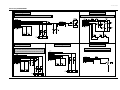
3-8
K221
K225
K200
K222
S.N.A.
S.N.A.
B456
S.N.A.
B462
(OPTIONAL)
B458
B570
B560
G542
B500
B484
B238
S.N.A.
S.N.A. : Service Not Available
B488
Exploded View and Parts List
3-3 Mechanical Parts (Bottom Side)
Samsung Electronics
Exploded View and Parts List
Loc. No
B238
B456
B458
B462
B484
B488
B500
B560
B570
G542
K200
K221
K222
K225
Parts No.
AC61-50660A
AC66-20576A
AC66-20574A
AC60-10517A
AC66-20580A
AC66-30543A
AC66-30542A
AC31-12017A
AC60-10514A
AC66-60051A
AC61-21012A
AC66-20581A
AC60-30306A
AC66-30547A
Samsung Electronics
Description ; Specification
Remark
SLEEVE-TENSION;-,POM M90-44,-,-,ID3,-,-,
GEAR-JOINT 1;-,POM SW-01,M1.0,Z22,-,PCD2
GEAR-JOINT 2;-,POM SW-01,M1.0,Z14,-,PCD1
SCREW-TAP TITE;-,PH,+,-,M2.6,L5,ZPC,-,YE
GEAR-LOADING DRIVE;-,POM SW-01,M1.0,Z32,
LEVER-S LOAD ASSY;-,-,-,-,-,X-9
LEVER-T LOAD ASSY;-,-,-,-,-,X-9
MOTOR-CAPSTAN;DMVCMC07C,-,X-9
SCREW-CAPSTAN;-,PH,+,M2.6,L6,BELT-PULLEY;-,5CM-70,2 * 2,-,71.3,-,X-9
HOLDER-CLUTCH ASSY;-,-,-,-,-,X-9
GEAR-CENTER ASSY;-,POM,M=O.5,-,HIGHT T.,
WASHER-SLIT;-,-,ID2.1,OD5.0,T0.5,-,POLYS
LEVER-UP DOWN ASSY;-,POM+SUS,-,-,-,X-9
3-9
Exploded View and Parts List
MEMO
3-10
Samsung Electronics
4. Electrical Parts List
Loc.No
Part No
-
-
Description ; Specification
ASSY-MAIN;X-9
Remark
S.N.A.
S.M.P.S. (230 VOLTAGE) PARTS
BD1SD1
AC27-92001M INDUCTOR;70UH-M RT BFS3565R2F,-,-,-,BD1SR1
3301-000297 CORE-FERRITE BEAD;AA,3.6x1.2x5.7mm,1400,
BD1SS2
AC27-92001M INDUCTOR;70UH-M RT BFS3565R2F,-,-,-,BD1SS3
AC27-92001M INDUCTOR;70UH-M RT BFS3565R2F,-,-,-,C1SD03
2201-000934 C-CERAMIC,DISC;3.3nF,20%,400V,Y5U,TP,18x
C1SD04
2201-000934 C-CERAMIC,DISC;3.3nF,20%,400V,Y5U,TP,18x
C1SD11
2401-003302 C-AL;47uF,20%,400V,GP,TP,18X31.5,7.
C1SD12
2201-000934 C-CERAMIC,DISC;3.3nF,20%,400V,Y5U,TP,18x
C1SR12
2401-000905 C-AL;22UF,20%,16V,BP,-,6X11,2.5MM
C1SR13
2301-000361 C-FILM,PEF;1.2NF,10%,50V,TP,-,5MM
C1SR14
2301-000445 C-FILM,PEF;4.7nF,5%,50V,TP,5.5x7x3mm,5mm
C1SS01
2305-001021 C-FILM,MPEF;100nF,20%,275V,TP,17.5x7x13.
C1SS02
2305-001021 C-FILM,MPEF;100nF,20%,275V,TP,17.5x7x13.
C1SS12
2201-000129 C-CERAMIC,DISC;100pF,10%,1KV,Y5P,TP,6x5,
C1SS31
2401-000385 C-AL;10uF,20%,100V,GP,TP,6.3x11,5
C1SS32
2401-001126 C-AL;330uF,20%,25V,WT,TP,10x12.5,5
C1SS33
2401-002162 C-AL;1000uF,20%,25V,WT,TP,10x20,5mm
C1SS34
2401-001126 C-AL;330uF,20%,25V,WT,TP,10x12.5,5
C1SS35
2401-001992 C-AL;2200uF,20%,10V,LZ,TP,10x25mm
C1SS36
2401-001479 C-AL;470uF,20%,10V,GP,-,-,TP
C1SS37
2401-003046 C-AL;47uF,20%,50V,WT,TP,6.3x11,2.5
VFD MODEL OPTION
C1SS38
2401-001479 C-AL;470uF,20%,10V,GP,-,-,TP
VFD MODEL OPTION
C1SS39
2301-000129 C-FILM,PEF;100nF,5%,50V,10X9X4.3X5,5mm,T
C1SS40
2301-000381 C-FILM,PEF;10nF,5%,50V,TP,6.5x5.5x3mm
VFD MODEL OPTION
C1SS41
2301-000423 C-FILM,PEF;3.3NF,5%,100V,TP,7X10X4.5MM,5
CN1SS1
3711-000178 CONNECTOR-HEADER;1WALL,2P,1R,3.96mm,STRA
D1SD31
0402-001195 DIODE-RECTIFIER;F1T4,400V,1.0A,TS-1,TP
D1SD32
0402-001195 DIODE-RECTIFIER;F1T4,400V,1.0A,TS-1,TP
VFD MODEL OPTION
D1SR11
0401-000101 DIODE-SWITCHING;1N4148,100V,200mA,DO-35,
D1SS01
0402-001196 DIODE-RECTIFIER;1T5,600V,1A,TS-1,TP
D1SS02
0402-001196 DIODE-RECTIFIER;1T5,600V,1A,TS-1,TP
D1SS03
0402-001196 DIODE-RECTIFIER;1T5,600V,1A,TS-1,TP
D1SS04
0402-001196 DIODE-RECTIFIER;1T5,600V,1A,TS-1,TP
D1SS11
0402-000276 DIODE-RECTIFIER;UF4007,1KV,1A,DO-41,TP
D1SS12
0402-001195 DIODE-RECTIFIER;F1T4,400V,1.0A,TS-1,TP
D1SS31
0402-001195 DIODE-RECTIFIER;F1T4,400V,1.0A,TS-1,TP
D1SS32
0402-001194 DIODE-RECTIFIER;UG2D,200V,2A,DO-204AC,TP
D1SS33
0404-000128 DIODE-SCHOTTKY;FMB-G14L,45V,5A,TO-220F,T
HI-FI ONLY
D1SS33
0402-000431 DIODE-SCHOTTKY;FML-M02S,45V,5A,TO-220F,T
MONO ONLY
D1SS44
0402-001195 DIODE-RECTIFIER;F1T4,400V,1.0A,TS-1,TP
VFD MODEL OPTION
F1SS01
3601-001123 FUSE-FERRULE;250V,1.6A,TIME-LAG,CERAMIC,
IC1SS1
0604-001028 PHOTO-COUPLER;TR,50-600%,250mW,DIP-4,ST
IC1SS2
AC14-12006D IC;KA431Z,TO-92,TAPING
L1SS01
AC29-30050B FILTER-LINE NOISE;-,400uH,-,AC250V,TR12.
L1SS02
AC29-30050C FILTER-LINE NOISE;-,20mH,0.35A,AC250V,BS
L1SS31
AC27-12001N COIL-CHOKE;10UH-15%,RA,K-30,Q80,150KHZ,L1SS32
AC27-12001N COIL-CHOKE;10UH-15%,RA,K-30,Q80,150KHZ,PT1SS1
AC26-20120L TRANS-SWITCHING;DP,230V,UL/CSA/DEMKO,EE2
Q1SR01
0502-001050 TR-POWER;2SC4517A,NPN,30W,TO-220,ST,10Q1SR12
0501-000442 TR-SMALL SIGNAL;KTC3203-Y,NPN,400MW,T0-9
R1SD11
2001-000305 R-CARBON;110Kohm,5%,1/8W,AA,TP,1.8x3.2m
R1SD12
2001-000003 R-CARBON;330ohm,5%,1/8W,AA,TP,1.8x3.2mm
R1SD13
2001-000305 R-CARBON;110Kohm,5%,1/8W,AA,TP,1.8x3.2m
R1SD14
2001-000305 R-CARBON;110Kohm,5%,1/8W,AA,TP,1.8x3.2m
R1SD15
2001-000305 R-CARBON;110Kohm,5%,1/8W,AA,TP,1.8x3.2m
R1SD16
2006-000273 R-CEMENT;27Kohm,5%,2W,CA,BK,6.4x27x6.4m
R1SD31
2001-000515 R-CARBON;220ohm,5%,1/8W,AA,TP,1.8x3.2mm
R1SD32
2001-000221 R-CARBON;1.2KOHM,5%,1/8W,AA,TP,R1SR11
2003-000119 R-METAL OXIDE;0.68ohm,5%,2W,AE,TP,6x16mm
Samsung Electronics
Loc.No
R1SR12
R1SR14
R1SS10
R1SS13
R1SS32
R1SS33
R1SS34
VA1SS1
ZD1SS1
Part No
2003-000264
2001-000003
2006-000262
2003-000148
2001-000429
2004-000869
2004-000459
1405-001026
0403-000571
Description ; Specification
Remark
R-METAL OXIDE;300ohm,5%,1W,AD,TP,4.3x12m
R-CARBON;330ohm,5%,1/8W,AA,TP,1.8x3.2mm
R-CEMENT;2.7ohm,10%,2W,CB,ST,7.5x11x20.
R-METAL OXIDE;100OHM,5%,2W,AE,TP,6X16MM
R-CARBON;1KOHM,5%,1/8W,AA,TP,R-METAL;3Kohm,1%,1/8W,AA,TP,1.8x3.2mm
R-METAL;2.2Kohm,1%,1/8W,AA,TP,1.8x3.2m
VARISTOR;470V,600A,9x7mm,TP
DIODE-ZENER;UZP43B,43V,40-46V,1W,DO-41,T
S.M.P.S. (FREE VOLTAGE) PARTS
BD1SD1
AC27-92001M INDUCTOR;70UH-M RT BFS3565R2F,-,-,-,BD1SF1
AC27-92001M INDUCTOR;70UH-M RT BFS3565R2F,-,-,-,BD1SS2
AC27-92001M INDUCTOR;70UH-M RT BFS3565R2F,-,-,-,BD1SS3
AC27-92001M INDUCTOR;70UH-M RT BFS3565R2F,-,-,-,C1SD03
2201-000934 C-CERAMIC,DISC;3.3nF,20%,400V,Y5U,TP,18x
C1SD04
2201-000934 C-CERAMIC,DISC;3.3nF,20%,400V,Y5U,TP,18x
C1SD11
2401-003303 C-AL;82uF,20%,400V,GP,BK,22X30,10
C1SD12
2301-000140 C-FILM,PEF;10nF,10%,630V,BK,16.5X9.5X5.7
C1SF12
2401-000970 C-AL;22uF,20%,50V,WT,TP,5x11,5
C1SF13
2301-000224 C-FILM,PEF;22nF,5%,50V,TP,7.4x3.9x13mm
C1SF14
2401-001915 C-AL;1uF,20%,50V,GP,TP,3x5,5
C1SF15
2301-000224 C-FILM,PEF;22nF,5%,50V,TP,7.4x3.9x13mm
C1SS01
2305-001021 C-FILM,MPEF;100nF,20%,275V,TP,17.5x7x13.
C1SS02
2305-001021 C-FILM,MPEF;100nF,20%,275V,TP,17.5x7x13.
C1SS12
2201-000129 C-CERAMIC,DISC;100pF,10%,1KV,Y5P,TP,6x5,
C1SS31
2401-000385 C-AL;10uF,20%,100V,GP,TP,6.3x11,5
C1SS32
2401-001126 C-AL;330uF,20%,25V,WT,TP,10x12.5,5
C1SS33
2401-002162 C-AL;1000uF,20%,25V,WT,TP,10x20,5mm
C1SS34
2401-001126 C-AL;330uF,20%,25V,WT,TP,10x12.5,5
C1SS35
2401-001992 C-AL;2200uF,20%,10V,LZ,TP,10x25mm
C1SS36
2401-001479 C-AL;470uF,20%,10V,GP,-,-,TP
C1SS37
2401-003046 C-AL;47uF,20%,50V,WT,TP,6.3x11,2.5
VFD MODEL OPTION
C1SS38
2401-001479 C-AL;470uF,20%,10V,GP,-,-,TP
VFD MODEL OPTION
C1SS39
2301-000129 C-FILM,PEF;100nF,5%,50V,10X9X4.3X5,5mm,T
C1SS40
2301-000381 C-FILM,PEF;10nF,5%,50V,TP,6.5x5.5x3mm,5m VFD MODEL OPTION
C1SS41
2301-000423 C-FILM,PEF;3.3NF,5%,100V,TP,7X10X4.5MM,5
CN1SS1
3711-000178 CONNECTOR-HEADER;1WALL,2P,1R,3.96mm,STRA
D1SD31
0402-001195 DIODE-RECTIFIER;F1T4,400V,1.0A,TS-1,TP
D1SD32
0402-001195 DIODE-RECTIFIER;F1T4,400V,1.0A,TS-1,TP
VFD MODEL OPTION
D1SS01
0402-001196 DIODE-RECTIFIER;1T5,600V,1A,TS-1,TP
D1SS02
0402-001196 DIODE-RECTIFIER;1T5,600V,1A,TS-1,TP
D1SS03
0402-001196 DIODE-RECTIFIER;1T5,600V,1A,TS-1,TP
D1SS04
0402-001196 DIODE-RECTIFIER;1T5,600V,1A,TS-1,TP
D1SS11
0402-000276 DIODE-RECTIFIER;UF4007,1KV,1A,DO-41,TP
D1SS12
0402-001195 DIODE-RECTIFIER;F1T4,400V,1.0A,TS-1,TP
D1SS31
0402-001195 DIODE-RECTIFIER;F1T4,400V,1.0A,TS-1,TP
D1SS32
0402-001194 DIODE-RECTIFIER;UG2D,200V,2A,DO-204AC,TP
D1SS33
0404-000128 DIODE-SCHOTTKY;FMB-G14L,45V,5A,TO-220F,T
HI-FI ONLY
D1SS33
0402-000431 DIODE-SCHOTTKY;FML-M02S,45V,5A,TO-220F,T
MONO ONLY
D1SS44
0402-001195 DIODE-RECTIFIER;F1T4,400V,1.0A,TS-1,TP
VFD MODEL OPTION
F1SS01
3601-001123 FUSE-FERRULE;250V,1.6A,TIME-LAG,CERAMIC,
IC1SF1
1203-001049 IC-PWM CONTROLLER:1L0380,TO-220F,4P,10MI
IC1SS1
0604-001028 PHOTO-COUPLER;TR,50-600%,250mW,DIP-4,ST
IC1SS2
AC14-12006D IC;KA431Z,TO-92,TAPING
L1SS01
AC29-30050B FILTER-LINE NOISE;-,400uH,-,AC250V,TR12.
L1SS02
AC29-30050C FILTER-LINE NOISE;-,20mH,0.35A,AC250V,BS
L1SS31
AC27-12001N COIL-CHOKE;10UH-15%,RA,K-30,Q80,150KHZ,L1SS32
AC27-12001N COIL-CHOKE;10UH-15%,RA,K-30,Q80,150KHZ,PT1SS1
AC26-20120K TRANS-SWITCHING;DP,100V-240V,DEMKO,EE282
R1SD11
2001-000076 R-CARBON;47Kohm,5%,1/4W,AA,TP,2.4x6.4mm
R1SD12
2001-000302 R-CARBON;10ohm,5%,1/8W,AA,TP,1.8x3.2mm
4-1
Electrical Parts List
Loc.No
Part No
R1SD13
R1SD14
R1SD15
R1SD16
R1SD31
R1SD32
R1SS10
R1SS11
R1SS13
D1SS31
R1SS32
R1SS33
R1SS34
VA1SS1
ZD1SF1
ZD1SF2
ZD1SS1
2001-000076
2001-000076
2001-000076
2003-000994
2001-000515
2001-000221
2006-000262
2003-000994
2003-000148
0402-001195
2001-000429
2004-000869
2004-000459
1405-001026
0403-000539
0403-000294
0403-000571
POWER DRIVE PARTS
C1P101
2401-003107
C1P102
2401-002144
C1P103
2401-000598
C1P104
2401-002299
C1P105
2401-002095
C1P106
2401-003107
C1P107
2401-003107
C1P108
2401-002095
C1P110
2401-000598
C1P115
2401-000598
C1P116
2401-000598
C1P117
2401-000598
D1P101
0401-000101
D1P103
0402-000127
D1P104
0402-000127
D1P105
0402-000127
D1P108
0402-000127
D1P109
0401-000101
D1P113
0402-000127
D1P114
0401-000101
D1P116
0401-000101
D1P117
0401-000101
D1P118
0402-000127
DDC101
0402-000127
DDC102
0402-000127
DDC103
0402-000127
DDC104
0402-000127
DDC105
0402-000127
DDC106
0402-000127
JC803
AC37-22002R
Q1P101
0501-000616
Q1P102
0501-000616
Q1P103
0501-000616
Q1P104
0501-000610
Q1P105
0504-000116
Q1P108
0501-000442
Q1P114
0501-000616
Q1P115
0504-000142
Q1P116
0501-000398
Q1P117
0501-000442
R1P103
2001-000034
R1P105
2001-000273
R1P106
2001-000611
R1P107
2001-000449
R1P108
2001-000449
R1P109
2001-000038
R1P110
2001-000038
Description ; Specification
Remark
R-CARBON;47Kohm,5%,1/4W,AA,TP,2.4x6.4mm
R-CARBON;47Kohm,5%,1/4W,AA,TP,2.4x6.4mm
R-CARBON;47Kohm,5%,1/4W,AA,TP,2.4x6.4mm
R-METAL OXIDE(S);33Kohm,5%,2W,AF,TP,3.9x
R-CARBON;220ohm,5%,1/8W,AA,TP,1.8x3.2mm
R-CARBON;1.2KOHM,5%,1/8W,AA,TP,R-CEMENT;2.7ohm,10%,2W,CB,ST,7.5x11x20.
R-METAL OXIDE(S);33Kohm,5%,2W,AF,TP,3.9x
R-METAL OXIDE;100OHM,5%,2W,AE,TP,6X16MM
DIODE-RECTIFIER;F1T4,400V,1.0A,TS-1,TP
R-CARBON;1KOHM,5%,1/8W,AA,TP,R-METAL;3Kohm,1%,1/8W,AA,TP,1.8x3.2mm
R-METAL;2.2Kohm,1%,1/8W,AA,TP,1.8x3.2m
VARISTOR;470V,600A,9x7mm,TP
DIODE-ZENER;MTZ18C,18V,17.42-18.33V,500m
DIODE-ZENER;MTZ4.7B,4.7V,4.55-4.80V,500m
DIODE-ZENER;UZP43B,43V,40-46V,1W,DO-41,T
C-AL;47uF,20%,16V,GP,TP,5x7,5
CANAL OPTION
C-AL;47uF,20%,16V,GP,TP,5x11,5
C-AL;1uF,20%,50V,GP,TP,4x7,5
C-AL;4.7uF,20%,50V,GP,TP,5x7,5
C-AL;47uF,20%,25V,GP,TP,6.3x5,5mm
C-AL;47uF,20%,16V,GP,TP,5x7,5
C-AL;47uF,20%,16V,GP,TP,5x7,5
C-AL;47uF,20%,25V,GP,TP,6.3x5,5mm
C-AL;1uF,20%,50V,GP,TP,4x7,5
C-AL;1uF,20%,50V,GP,TP,4x7,5
C-AL;1uF,20%,50V,GP,TP,4x7,5
CANAL OPTION
C-AL;1uF,20%,50V,GP,TP,4x7,5
DIODE-SWITCHING;1N4148,100V,200mA,DO-35,
DIODE-RECTIFIER;1N4002,100V,1A,DO-41,TP
DIODE-RECTIFIER;1N4002,100V,1A,DO-41,TP
DIODE-RECTIFIER;1N4002,100V,1A,DO-41,TP
DIODE-RECTIFIER;1N4002,100V,1A,DO-41,TP
DIODE-SWITCHING;1N4148,100V,200mA,DO-35,
DIODE-RECTIFIER;1N4002,100V,1A,DO-41,TP
DIODE-SWITCHING;1N4148,100V,200mA,DO-35, CANAL OPTION
DIODE-SWITCHING;1N4148,100V,200mA,DO-35, CANAL OPTION
DIODE-SWITCHING;1N4148,100V,200mA,DO-35,
DIODE-RECTIFIER;1N4002,100V,1A,DO-41,TP
DIODE-RECTIFIER;1N4002,100V,1A,DO-41,TP
VCP ONLY
DIODE-RECTIFIER;1N4002,100V,1A,DO-41,TP
VCP ONLY
DIODE-RECTIFIER;1N4002,100V,1A,DO-41,TP
VCP ONLY
DIODE-RECTIFIER;1N4002,100V,1A,DO-41,TP
VCP ONLY
DIODE-RECTIFIER;1N4002,100V,1A,DO-41,TP
VCP ONLY
DIODE-RECTIFIER;1N4002,100V,1A,DO-41,TP
VCP ONLY
JACK-DC;12.5mm,DUAE-9812,4P,BULK,8PIN
VCP ONLY
TR-SMALL SIGNAL;KSC2328A-Y,NPN,1W,TO-92L
TR-SMALL SIGNAL;KSC2328A-Y,NPN,1W,TO-92L
TR-SMALL SIGNAL;KSC2328A-Y,NPN,1W,TO-92L
TR-SMALL SIGNAL;KSA928A-Y,PNP,1W,TO-92L,
TR-DIGITAL;KSR1001,NPN,300mW,4.7K-4.7K,T
TR-SMALL SIGNAL;KTC3203-Y,NPN,400MW,T0-9 CANAL OPTION
TR-SMALL SIGNAL;KSC2328A-Y,NPN,1W,TO-92L
TR-DIGITAL;KSR2001,PNP,300mW,4.7K-4.7K,T
TR-SMALL SIGNAL;KSC945,NPN,250mW,TO-92,T
TR-SMALL SIGNAL;KTC3203-Y,NPN,400MW,T0-9
R-CARBON;220OHM,5%,1/4W,AA,TP,R-CARBON;100KOHM,5%,1/8W,AA,TP,R-CARBON;3.9KOHM,5%,1/4W,AA,TP,R-CARBON;2.2Kohm,5%,1/8W,AA,TP,1.8x3.2m
R-CARBON;2.2Kohm,5%,1/8W,AA,TP,1.8x3.2m
R-CARBON;390ohm,5%,1/4W,AA,TP,2.4x6.4mm VFD MODEL ONLY
R-CARBON;390ohm,5%,1/4W,AA,TP,2.4x6.4mm VFD MODEL ONLY
Loc.No
R1P111
R1P112
R1P117
R1P127
R1P128
R1P129
ZD1P01
ZD1P02
ZD1P03
ZD1P06
Part No
2001-000110
2001-000554
2001-000362
2001-000734
2001-000290
2001-000362
0403-001211
0403-000717
0403-000720
0403-001211
Description ; Specification
Remark
R-CARBON;10ohm,5%,1/4,AA,TP,2.4X6.4mm VFD MODEL ONLY
R-CARBON;270ohm,5%,1/8W,AA,TP,1.8x3.2mm
R-CARBON;150ohm,5%,1/8W,AA,TP,1.8x3.2mm
R-CARBON;4.7KOHM,5%,1/8W,AA,TP,R-CARBON;10KOHM,5%,1/8W,AA,TP,R-CARBON;150ohm,5%,1/8W,AA,TP,1.8x3.2mm CANAL OPTION
DIODE-ZENER;MTZJ12B,12V,11.44-12.03V,500
DIODE-ZENER;MTZJ5.1B,5.1V,4.94-5.2V,500m
DIODE-ZENER;MTZJ9.1B,9.1V,8.57-9.01V,500
DIODE-ZENER;MTZJ12B,12V,11.44-12.03V,500
CANAL OPTION
SYSTEM CONTROL/SERVO PARTS
C601
2202-002037 C-CERAMIC,MLC-AXIAL;100nF,80-20%,50V,Y5V
C602
2202-002037 C-CERAMIC,MLC-AXIAL;100nF,80-20%,50V,Y5V
C603
2401-003107 C-AL;47uF,20%,16V,GP,TP,5x7,5
C604
2202-000797 C-CERAMIC,MLC-AXIAL;10NF,30%,16V,Y5S,TP,
C605
2202-000797 C-CERAMIC,MLC-AXIAL;10NF,30%,16V,Y5S,TP,
C607
2401-001775 C-AL;470nF,20%,50V,GP,TP,4x7,5
C608
2401-002259 C-AL;0.1F,+80-20%,5.5V,-,TP,12.5x11
BACK-UP(1HR)
C608
2401-000118 C-AL;1000uF,20%,10V,GP,TP,10x12.5,5
BACK-UP(30SECONDS)
C610
2202-000797 C-CERAMIC,MLC-AXIAL;10NF,30%,16V,Y5S,TP,
C611
2301-000392 C-FILM,PEF;15nF,5%,50V,TP,6.5x8.5x3.2mm,
C612
2401-000118 C-AL;1000uF,20%,10V,GP,TP,10x12.5,5
C614
2202-002037 C-CERAMIC,MLC-AXIAL;100nF,80-20%,50V,Y5V
C618
2401-002095 C-AL;47uF,20%,25V,GP,TP,6.3x5,5mm
C619
2202-000797 C-CERAMIC,MLC-AXIAL;10NF,30%,16V,Y5S,TP,
C620
2202-000797 C-CERAMIC,MLC-AXIAL;10NF,30%,16V,Y5S,TP,
C621
2401-002095 C-AL;47uF,20%,25V,GP,TP,6.3x5,5mm
C622
2301-000471 C-FILM,PEF;68nF,5%,50V,TP,9x12x4.5mm,5mm
C623
2202-000807 C-CERAMIC,MLC-AXIAL;22nF,+80-20%,25V,Y5V
C624
2202-000205 C-CERAMIC,MLC-AXIAL;22pF,5%,50V,SL,TP,1.
C625
2202-000205 C-CERAMIC,MLC-AXIAL;22pF,5%,50V,SL,TP,1.
C626
2202-000205 C-CERAMIC,MLC-AXIAL;22pF,5%,50V,SL,TP,1.
C627
2202-000205 C-CERAMIC,MLC-AXIAL;22pF,5%,50V,SL,TP,1.
C628
2202-002037 C-CERAMIC,MLC-AXIAL;100nF,80-20%,50V,Y5V
C633
2202-000797 C-CERAMIC,MLC-AXIAL;10NF,30%,16V,Y5S,TP,
C634
2202-000797 C-CERAMIC,MLC-AXIAL;10NF,30%,16V,Y5S,TP,
C635
2202-000183 C-CERAMIC,MLC-AXIAL;2.2NF,20%,16V,Y5R,TP
C636
2202-000183 C-CERAMIC,MLC-AXIAL;2.2NF,20%,16V,Y5R,TP
C637
2202-000263 C-CERAMIC,MLC-AXIAL;470pF,10%,50V,Y5P,TP
C638
2401-000918 C-AL;22uF,20%,16V,GP,-,6.3x7,5
C639
2202-000121 C-CERAMIC,MLC-AXIAL;100pF,10%,50V,Y5P,TP
C640
2202-002037 C-CERAMIC,MLC-AXIAL;100nF,80-20%,50V,Y5V
C641
2401-002165 C-AL;100uF,20%,16V,GP,TP,6.3x7,5
C642
2401-002095 C-AL;47uF,20%,25V,GP,TP,6.3x5,5mm
C643
2401-002095 C-AL;47uF,20%,25V,GP,TP,6.3x5,5mm
C645
2401-003107 C-AL;47uF,20%,16V,GP,TP,5x7,5
C646
2202-002037 C-CERAMIC,MLC-AXIAL;100nF,80-20%,50V,Y5V
C690
2301-000471 C-FILM,PEF;68nF,5%,50V,TP,9x12x4.5mm,5mm
C691
2202-000797 C-CERAMIC,MLC-AXIAL;10NF,30%,16V,Y5S,TP,
C699
2301-000445 C-FILM,PEF;4.7nF,5%,50V,TP,5.5x7x3mm,5mm
CN601
AC39-20817S LEAD CONNECTOR-ASSY;DP,SMH200-02,YBH200CN602
3708-001163 CONNECTOR-FPC/FC/PIC;5P,1.25mm,STRAIGHT,
CN604
3711-003749 CONNECTOR-HEADER;BOX,8P,2R,2mm,STRAIGHT,
D603
0401-000101 DIODE-SWITCHING;1N4148,100V,200mA,DO-35,
D604
0401-000101 DIODE-SWITCHING;1N4148,100V,200mA,DO-35,
D605
0402-000127 DIODE-RECTIFIER;1N4002,100V,1A,DO-41,TP
ULP OPTION
D607
0401-000101 DIODE-SWITCHING;1N4148,100V,200mA,DO-35,
D611
0402-000127 DIODE-RECTIFIER;1N4002,100V,1A,DO-41,TP
D613
0401-000101 DIODE-SWITCHING;1N4148,100V,200mA,DO-35,
D620
0402-000127 DIODE-RECTIFIER;1N4002,100V,1A,DO-41,TP
D621
0401-000101 DIODE-SWITCHING;1N4148,100V,200mA,DO-35,
IC601
AC09-00008C IC-MCU;UPD784927GF-111-3BA,100P,-,N90-11
VCR ONLY
IC601
AC09-00010A IC-MCU;UPD784915AGF-116-3BA
VCP ONLY
IC602
1003-001162 IC-MOTOR DRIVER;KA3082,SIP,10PIN,25MIL,D
IC604
AC14-12006C IC;KA7533,DIP,3 ULP : ULTRA LONG PLAY
4-2
Samsung Electronics
Electrical Parts List
Loc.No
IC605
IC605
IC605
IC608
L601
L603
L604
L605
LD601
PT601
PT602
Q602
R601
R602
R603
R603
R604
R605
R608
R609
R613
R641
R642
R644
R650
R651
R652
R654
R655
R656
R657
R660
R661
R666
R667
R668
R669
R670
R671
R672
R673
R674
R675
R676
R677
R678
R679
R682
R685
R687
R690
R691
R692
R693
R694
S601
S602
SW601
SW602
W229
XT601
XT602
Part No
1103-001116
1103-001101
1103-000190
1203-000515
AC27-92001B
AC27-92001B
AC27-92001B
AC27-92001B
0601-000517
0604-001122
0604-001122
0501-000398
2001-000411
2001-000281
2001-000281
2001-000290
2001-000429
2001-000429
2001-000864
2001-000864
2001-000429
2001-000780
2001-000780
2001-000429
2003-000259
2001-000010
2001-000568
2001-000812
2001-000786
2001-000241
2001-000010
2001-000786
2001-000660
2001-000290
2001-000290
2001-000281
2001-000281
2001-000734
2001-000734
2001-000734
2001-000429
2001-000290
2001-000362
2001-000633
2001-000522
2001-000522
2001-000515
2001-000522
2001-000660
2001-000429
2001-000864
2001-000515
2001-000429
2001-000429
2001-000429
0603-001011
0603-001011
AC34-20100A
AC34-20100B
2001-000591
2801-003318
2801-003139
AUDIO/VIDEO PARTS
C301
2401-001919
C302
2301-000283
Samsung Electronics
Description ; Specification
Remark
IC-EEPROM;24C16,2Kx8BIT,DIP,8P,300MIL,10 With SRC FUCTION
IC-EEPROM;24C08,1028x8BIT,DIP,8P,300MIL, NON-SRC FUNCTION
IC-EEPROM;24C02,256x8BIT,DIP,8P,300MIL,1M.E.ASIA REGION ONLY
IC-VOL. DETECTOR;7042,TO-92,3P,177MIL,PL
COIL-PEAKING AXIAL;BAL04ST101K,-,-,-,COIL-PEAKING AXIAL;BAL04ST101K,-,-,-,COIL-PEAKING AXIAL;BAL04ST101K,-,-,-,COIL-PEAKING AXIAL;BAL04ST101K,-,-,-,LED-IR;RECTANGULA,4x6.0mm,75mW,6V,950
PHOTO-INTERRUPTER;TR,0.065%,150mW,DIP-4,
PHOTO-INTERRUPTER;TR,0.065%,150mW,DIP-4,
TR-SMALL SIGNAL;KSC945,NPN,250mW,TO-92,T
R-CARBON;18KOHM,5%,1/8W,AA,TP,ULP OPTION
R-CARBON;100ohm,5%,1/8W,AA,TP,1.8x FRANCE REGION ONLY
R-CARBON;100ohm,5%,1/8W,AA,TP,1.8x FRANCE REGION ONLY
R-CARBON;10KOHM,5%,1/8W,AA,TP,- NON-FRANCE REGION ONLY
R-CARBON;1KOHM,5%,1/8W,AA,TP,R-CARBON;1KOHM,5%,1/8W,AA,TP,R-CARBON;56Kohm,5%,1/8W,AA,TP,1.8x3.2mm
R-CARBON;56Kohm,5%,1/8W,AA,TP,1.8x3.2mm
R-CARBON;1KOHM,5%,1/8W,AA,TP,R-CARBON;470OHM,5%,1/8W,AA,TP,R-CARBON;470OHM,5%,1/8W,AA,TP,R-CARBON;1KOHM,5%,1/8W,AA,TP,R-METAL OXIDE;3.9OHM,5%,2W,AE,TP,6X16MM
R-CARBON;68Kohm,5%,1/8W,AA,TP,1.8x3.2mm
R-CARBON;27ohm,5%,1/8W,AA,TP,1.8x3.2mm
R-CARBON;5.6Kohm,5%,1/8W,AA,TP,1.8x3.2m
R-CARBON;47Kohm,5%,1/8W,AA,TP,1.8x3.2mm
R-CARBON;1.5Kohm,5%,1/8W,AA,TP,1.8x3.2m
R-CARBON;68Kohm,5%,1/8W,AA,TP,1.8x3.2mm
R-CARBON;47Kohm,5%,1/8W,AA,TP,1.8x3.2mm
R-CARBON;33Kohm,5%,1/8W,AA,TP,1.8x3.2mm
R-CARBON;10KOHM,5%,1/8W,AA,TP,R-CARBON;10KOHM,5%,1/8W,AA,TP,R-CARBON;100ohm,5%,1/8W,AA,TP,1.8x3.2mm
R-CARBON;100ohm,5%,1/8W,AA,TP,1.8x3.2mm
R-CARBON;4.7KOHM,5%,1/8W,AA,TP,R-CARBON;4.7KOHM,5%,1/8W,AA,TP,R-CARBON;4.7KOHM,5%,1/8W,AA,TP,R-CARBON;1KOHM,5%,1/8W,AA,TP,R-CARBON;10KOHM,5%,1/8W,AA,TP,R-CARBON;150ohm,5%,1/8W,AA,TP,1.8x3.2mm
R-CARBON;30Kohm,5%,1/8W,AA,TP,1.8x3.2mm
R-CARBON;22Kohm,5%,1/8W,AA,TP,1.8x3.2mm
R-CARBON;22Kohm,5%,1/8W,AA,TP,1.8x3.2mm
R-CARBON;220ohm,5%,1/8W,AA,TP,1.8x3.2mm
R-CARBON;22Kohm,5%,1/8W,AA,TP,1.8x3.2mm
R-CARBON;33Kohm,5%,1/8W,AA,TP,1.8x3.2mm
R-CARBON;1KOHM,5%,1/8W,AA,TP,R-CARBON;56Kohm,5%,1/8W,AA,TP,1.8x3.2mm
R-CARBON;220ohm,5%,1/8W,AA,TP,1.8x3.2mm
R-CARBON;1KOHM,5%,1/8W,AA,TP,R-CARBON;1KOHM,5%,1/8W,AA,TP,R-CARBON;1KOHM,5%,1/8W,AA,TP,PHOTO-TR;NPN,35V,6V,50mA,75mW,BK
PHOTO-TR;NPN,35V,6V,50mA,75mW,BK
SWITCH-MODE;-,-,X-9,SWITCH-REC;-,-,X-9,R-CARBON;3.3KOHM,5%,1/8W,AA,TP,CRYSTAL-UNIT;32.768KHz,20ppm,28-AAP,12.5
CRYSTAL-UNIT;8MHz,50ppm,28-AAA,22pF,80oh
C-AL;2.2UF,20%,50V,-,TP,4X7MM,5
C-FILM,PEF;47nF,5%,100V,TP,7.3X7X3.2X5,5
Loc.No
C303
C304
C305
C306
C307
C308
C309
C310
C311
C312
C313
C314
C315
C316
C318
C320
C321
C322
C323
C324
C325
C326
C327
C328
C329
C330
C331
C332
C333
C334
C335
C336
C337
C338
C339
C340
C341
C342
C343
C345
C346
C347
C348
C349
C350
C360
C380
C381
C390
C399
C3A01
C3A02
C3A04
C3A05
C3A07
C3A08
C3A09
C3A10
C3A12
C3A13
C3A14
C3A15
C3A16
C3A17
C3A18
C3A21
Part No
2401-000598
2202-000216
2202-000164
2202-000814
2202-000162
2202-000797
2401-000598
2401-000414
2401-000918
2202-000121
2202-000173
2401-001775
2401-000414
2202-002037
2202-002037
2401-000598
2401-000414
2401-000598
2202-000797
2202-000797
2202-000797
2202-002037
2401-003107
2202-000797
2202-000797
2202-000797
2401-003107
2202-002037
2401-000598
2301-000402
2401-001915
2401-000598
2202-000807
2202-000797
2202-000854
2202-000807
2401-003107
2202-002037
2202-000797
2201-002031
2401-003107
2202-000286
2202-000286
2202-000849
2202-000797
2401-000414
2202-000849
2202-000797
2202-002037
2202-002037
2401-003122
2202-002037
2202-002037
2202-002037
2301-000392
2301-001014
2301-001014
2301-000314
2401-003107
2301-000161
2301-001014
2301-000381
2401-002299
2401-000918
2301-000402
2301-000008
Description ; Specification
C-AL;1uF,20%,50V,GP,TP,4x7,5
C-CERAMIC,MLC-AXIAL;.027NF,5%,50V,SL,TP,
C-CERAMIC,MLC-AXIAL;.18NF,10%,50V,Y5P,TP
C-CERAMIC,MLC-AXIAL;390pF,10%,50V,Y5P,TP
C-CERAMIC,MLC-AXIAL;.015NF,5%,50V,SL,TP,
C-CERAMIC,MLC-AXIAL;10NF,30%,16V,Y5S,TP,
C-AL;1uF,20%,50V,GP,TP,4x7,5
C-AL;10uF,20%,16V,GP,TP,4x7,5
C-AL;22uF,20%,16V,GP,-,6.3x7,5
C-CERAMIC,MLC-AXIAL;100pF,10%,50V,Y5P,TP
C-CERAMIC,MLC-AXIAL;1nF,10%,50V,Y5P,TP,1
C-AL;470nF,20%,50V,GP,TP,4x7,5
C-AL;10uF,20%,16V,GP,TP,4x7,5
C-CERAMIC,MLC-AXIAL;100nF,80-20%,50V,Y5V
C-CERAMIC,MLC-AXIAL;100nF,80-20%,50V,Y5V
C-AL;1uF,20%,50V,GP,TP,4x7,5
C-AL;10uF,20%,16V,GP,TP,4x7,5
C-AL;1uF,20%,50V,GP,TP,4x7,5
C-CERAMIC,MLC-AXIAL;10NF,30%,16V,Y5S,TP,
C-CERAMIC,MLC-AXIAL;10NF,30%,16V,Y5S,TP,
C-CERAMIC,MLC-AXIAL;10NF,30%,16V,Y5S,TP,
C-CERAMIC,MLC-AXIAL;100nF,80-20%,50V,Y5V
C-AL;47uF,20%,16V,GP,TP,5x7,5
C-CERAMIC,MLC-AXIAL;10NF,30%,16V,Y5S,TP,
C-CERAMIC,MLC-AXIAL;10NF,30%,16V,Y5S,TP,
C-CERAMIC,MLC-AXIAL;10NF,30%,16V,Y5S,TP,
C-AL;47uF,20%,16V,GP,TP,5x7,5
C-CERAMIC,MLC-AXIAL;100nF,80-20%,50V,Y5V
C-AL;1uF,20%,50V,GP,TP,4x7,5
C-FILM,PEF;1nF,5%,50V,TP,5x7x2.8mm,5mm
C-AL;1uF,20%,50V,GP,TP,3x5,5
C-AL;1uF,20%,50V,GP,TP,4x7,5
C-CERAMIC,MLC-AXIAL;22nF,+80-20%,25V,Y5V
C-CERAMIC,MLC-AXIAL;10NF,30%,16V,Y5S,TP,
C-CERAMIC,MLC-AXIAL;47NF,30%,50V,Y5R,TP,
C-CERAMIC,MLC-AXIAL;22nF,+80-20%,25V,Y5V
C-AL;47uF,20%,16V,GP,TP,5x7,5
C-CERAMIC,MLC-AXIAL;100nF,80-20%,50V,Y5V
C-CERAMIC,MLC-AXIAL;10NF,30%,16V,Y5S,TP,
C-CERAMIC,DISC;5pF,0.25pF,50V,NPO,TP,5x3
C-AL;47uF,20%,16V,GP,TP,5x7,5
C-CERAMIC,MLC-AXIAL;56pF,5%,50V,SL,TP,1.
C-CERAMIC,MLC-AXIAL;56pF,5%,50V,SL,TP,1.
C-CERAMIC,MLC-AXIAL;18pF,5%,50V,CH,TP,3.
C-CERAMIC,MLC-AXIAL;10NF,30%,16V,Y5S,TP,
C-AL;10uF,20%,16V,GP,TP,4x7,5
C-CERAMIC,MLC-AXIAL;18pF,5%,50V,CH,TP,3.
C-CERAMIC,MLC-AXIAL;10NF,30%,16V,Y5S,TP,
C-CERAMIC,MLC-AXIAL;100nF,80-20%,50V,Y5V
C-CERAMIC,MLC-AXIAL;100nF,80-20%,50V,Y5V
C-AL;4.7uF,20%,50V,LL,TP,4X7,1.5
C-CERAMIC,MLC-AXIAL;100nF,80-20%,50V,Y5V
C-CERAMIC,MLC-AXIAL;100nF,80-20%,50V,Y5V
C-CERAMIC,MLC-AXIAL;100nF,80-20%,50V,Y5V
C-FILM,PEF;15nF,5%,50V,TP,6.5x8.5x3.2mm,
C-FILM,PEF;6.8nF,5%,50V,TP,7x3x6,5mm
C-FILM,PEF;6.8nF,5%,50V,TP,7x3x6,5mm
C-FILM,PEF;8.2nF,5%,50V,TP,6.5x3.0x5.5mm
C-AL;47uF,20%,16V,GP,TP,5x7,5
C-FILM,PEF;12nF,5%,50V,6.5X5.5X3.0X5,5mm
C-FILM,PEF;6.8nF,5%,50V,TP,7x3x6,5mm
C-FILM,PEF;10nF,5%,50V,TP,6.5x5.5x3mm,5m
C-AL;4.7uF,20%,50V,GP,TP,5x7,5
C-AL;22uF,20%,16V,GP,-,6.3x7,5
C-FILM,PEF;1nF,5%,50V,TP,5x7x2.8mm,5mm
C-FILM,PEF;2.2nF,5%,50V,TP,5.5X7X3,5mm
Remark
F-A/V OPTION
F-A/V OPTION
ULP OPTION
4-3
Electrical Parts List
Loc.No
Part No
C3A22
C3A23
C3A24
C3A25
C3A29
C3A30
C3A31
CN301
CN301
CN3A01
CN3A02
D302
FL3A01
IC301
IC301
L301
L302
L303
L304
L305
L306
L310
L3A01
L3A02
L3A03
Q302
Q303
Q304
Q308
Q309
Q310
Q3A01
Q3A03
Q3A04
Q3A05
Q3A06
Q3A07
Q3A08
R301
R302
R303
R304
R305
R306
R308
R309
R311
R312
R313
R314
R315
R316
R317
R318
R320
R321
R322
R324
R325
R326
R327
R328
R329
R330
R331
R332
2202-002037
2401-001169
2202-002037
2401-000918
2202-002037
2401-002144
2202-002037
3708-000391
3708-000395
3708-001302
3711-002445
0401-000101
AC27-80100A
1204-001410
1204-001403
2701-000206
2702-000106
AC27-92001B
2702-000106
2702-000106
2701-000119
2702-000106
2702-000120
AC27-92001B
2702-000106
0501-000303
0501-000398
0501-000398
0501-000398
0501-000398
0504-000203
0501-000303
0501-000442
0501-000442
0501-000442
0501-000303
0504-000203
0504-000203
2001-000449
2001-000429
2001-000258
2001-000977
2001-000258
2001-000232
2001-000429
2001-000723
2001-000429
2001-000241
2001-000515
2001-000924
2001-000472
2001-000221
2001-000003
2001-000003
2001-000009
2001-000290
2001-000539
2001-000554
2001-000472
2001-000832
2001-000832
2001-000734
2001-000472
2001-000734
2001-000515
2001-000281
4-4
Description ; Specification
Remark
C-CERAMIC,MLC-AXIAL;100nF,80-20%,50V,Y5V
MONO ONLY
C-AL;33UF,20%,16V,GP,-,6.3X7,2.5MM
C-CERAMIC,MLC-AXIAL;100nF,80-20%,50V,Y5V
C-AL;22uF,20%,16V,GP,-,6.3x7,5
C-CERAMIC,MLC-AXIAL;100nF,80-20%,50V,Y5V
C-AL;47uF,20%,16V,GP,TP,5x11,5
C-CERAMIC,MLC-AXIAL;100nF,80-20%,50V,Y5V
MONO ONLY
CONNECTOR-FPC/FC/PIC;10P,1.25MM,STRAIGHT
HI-FI ONLY
CONNECTOR-FPC/FC/PIC;8P,1.25MM,STRAIGHT,
MONO ONLY
CONNECTOR-FPC/FC/PIC;7P,1.25mm,STRAIGHT,
CONNECTOR-HEADER;BOX,2P,2R,1.5MM,STRAIGH
DIODE-SWITCHING;1N4148,100V,200mA,DO-35,
COIL-OSC;126QN-K5272YHC=K,-,AM
IC-VIDEO PROCESS;LA71590M,QFP,100P,-,PLA
PAL SYSTEM
IC-VIDEO PROCESS;LA71570M,QFP,100P,-,PLA
MULTI SYSTEM
INDUCTOR-AXIAL;56UH,5%,2.4X3.4MM
INDUCTOR-RADIAL;100uH,5%,6.2x7.4mm
COIL-PEAKING AXIAL;BAL04ST101K,-,-,-,INDUCTOR-RADIAL;100uH,5%,6.2x7.4mm
INDUCTOR-RADIAL;100uH,5%,6.2x7.4mm
INDUCTOR-AXIAL;120UH,5%,2.4X3.4MM
INDUCTOR-RADIAL;100uH,5%,6.2x7.4mm
INDUCTOR-RADIAL;15mH,5%,6.2x7.4mm
COIL-PEAKING AXIAL;BAL04ST101K,-,-,-,INDUCTOR-RADIAL;100uH,5%,6.2x7.4mm
TR-SMALL SIGNAL;KSA733,PNP,250mW,TO-92,T
TR-SMALL SIGNAL;KSC945,NPN,250mW,TO-92,T
TR-SMALL SIGNAL;KSC945,NPN,250mW,TO-92,T
TR-SMALL SIGNAL;KSC945,NPN,250mW,TO-92,T
TR-SMALL SIGNAL;KSC945,NPN,250mW,TO-92,T
TR-DIGITAL;KSR1004,NPN,300mW,47K-47K,TOHI-FI ONLY
TR-SMALL SIGNAL;KSA733,PNP,250mW,TO-92,T
TR-SMALL SIGNAL;KTC3203-Y,NPN,400MW,T0-9
TR-SMALL SIGNAL;KTC3203-Y,NPN,400MW,T0-9
TR-SMALL SIGNAL;KTC3203-Y,NPN,400MW,T0-9
TR-SMALL SIGNAL;KSA733,PNP,250mW,TO-92,T
TR-DIGITAL;KSR1004,NPN,300mW,47K-47K,TOULP OPTION
TR-DIGITAL;KSR1004,NPN,300mW,47K-47K,TOULP OPTION
R-CARBON;2.2Kohm,5%,1/8W,AA,TP,1.8x3.2m
R-CARBON;1KOHM,5%,1/8W,AA,TP,R-CARBON;1.8KOHM,5%,1/8W,AA,TP,R-CARBON;8.2Kohm,5%,1/8W,AA,TP,1.8x3.2m
R-CARBON;1.8KOHM,5%,1/8W,AA,TP,R-CARBON;1.3Kohm,5%,1/8W,AA,TP,1.8x3.2m
R-CARBON;1KOHM,5%,1/8W,AA,TP,R-CARBON;4.3Kohm,5%,1/8W,AA,TP,1.8x3.2m
R-CARBON;1KOHM,5%,1/8W,AA,TP,R-CARBON;1.5Kohm,5%,1/8W,AA,TP,1.8x3.2m
R-CARBON;220ohm,5%,1/8W,AA,TP,1.8x3.2mm
R-CARBON;680ohm,5%,1/8W,AA,TP,1.8x3.2mm
R-CARBON;2.7KOHM,5%,1/8W,AA,TP,R-CARBON;1.2KOHM,5%,1/8W,AA,TP,R-CARBON;330ohm,5%,1/8W,AA,TP,1.8x3.2mm
R-CARBON;330ohm,5%,1/8W,AA,TP,1.8x3.2mm
R-CARBON;20KOHM,5%,1/8W,AA,TP,R-CARBON;10KOHM,5%,1/8W,AA,TP,R-CARBON;24Kohm,5%,1/8W,AA,TP,1.8x3.2mm
R-CARBON;270ohm,5%,1/8W,AA,TP,1.8x3.2mm 2H’D LP OPTION
R-CARBON;2.7KOHM,5%,1/8W,AA,TP,R-CARBON;510ohm,5%,1/8W,AA,TP,1.8x3.2mm
R-CARBON;510ohm,5%,1/8W,AA,TP,1.8x3.2mm
R-CARBON;4.7KOHM,5%,1/8W,AA,TP,R-CARBON;2.7KOHM,5%,1/8W,AA,TP,R-CARBON;4.7KOHM,5%,1/8W,AA,TP,R-CARBON;220ohm,5%,1/8W,AA,TP,1.8x3.2mm
R-CARBON;100ohm,5%,1/8W,AA,TP,1.8x3.2mm
Loc.No
R333
R334
R335
R336
R339
R341
R342
R343
R344
R346
R3A01
R3A04
R3A05
R3A06
R3A07
R3A08
R3A09
R3A10
R3A11
R3A12
R3A13
R3A14
R3A16
R3A17
R3A18
R3A19
R3A21
R3A22
R3A23
R3A24
R3A25
R3A26
R3A27
R3A28
R3A28
R3A29
R3A30
R3A31
R3A32
R3A33
R3A35
R3A37
R3A40
R3A40
XT301
XT302
Part No
2001-000281
2001-000281
2001-000800
2001-000008
2001-000258
2001-001000
2001-000812
2001-001031
2001-000969
2001-000258
2001-000331
2001-000241
2001-000660
2001-000325
2001-000645
2001-000331
2001-000802
2001-000429
2001-000258
2001-000458
2001-000780
2001-000522
2001-000290
2001-000613
2001-000613
2001-000405
2001-000904
2001-000006
2001-000800
2001-000522
2001-000221
2001-000331
2001-000947
2001-000472
2001-000890
2001-000890
2001-000454
2001-000766
2001-000766
2001-000766
2001-000666
2001-000947
2001-000007
2001-000611
2801-001397
2801-003399
Description ; Specification
Remark
R-CARBON;100ohm,5%,1/8W,AA,TP,1.8x3.2mm
R-CARBON;100ohm,5%,1/8W,AA,TP,1.8x3.2mm
R-CARBON;5.1Kohm,5%,1/8W,AA,TP,1.8x3.2m
R-CARBON;15Kohm,5%,1/8W,AA,TP,1.8x3.2mm
R-CARBON;1.8KOHM,5%,1/8W,AA,TP,MULTI SYSTEM
R-CARBON;82Kohm,5%,1/8W,AA,TP,1.8x3.2mm
R-CARBON;5.6Kohm,5%,1/8W,AA,TP,1.8x3.2m
R-CARBON;91Kohm,5%,1/8W,AA,TP,1.8x3.2mm
HI-FI ONLY
R-CARBON;75ohm,5%,1/8W,AA,TP,1.8x3.2mm
F-A/V OPTION
R-CARBON;1.8KOHM,5%,1/8W,AA,TP,R-CARBON;12KOHM,5%,1/8W,AA,TP,R-CARBON;1.5Kohm,5%,1/8W,AA,TP,1.8x3.2m
R-CARBON;33Kohm,5%,1/8W,AA,TP,1.8x3.2mm
R-CARBON;120ohm,5%,1/8W,AA,TP,1.8x3.2mm
R-CARBON;330Kohm,5%,1/8W,AA,TP,1.8x3.2m
R-CARBON;12KOHM,5%,1/8W,AA,TP,R-CARBON;5.6Kohm,5%,1/8W,AA,TP,1.8x3.2m
R-CARBON;1KOHM,5%,1/8W,AA,TP,R-CARBON;1.8KOHM,5%,1/8W,AA,TP,R-CARBON;2.2ohm,5%,1/8W,AA,TP,1.8x3.2mm
R-CARBON;470OHM,5%,1/8W,AA,TP,R-CARBON;22Kohm,5%,1/8W,AA,TP,1.8x3.2mm
R-CARBON;10KOHM,5%,1/8W,AA,TP,R-CARBON;3.9KOHM,5%,1/8W,AA,TP,R-CARBON;3.9KOHM,5%,1/8W,AA,TP,R-CARBON;180ohm,5%,1/8W,AA,TP,1.8x3.2mm
R-CARBON;620ohm,5%,1/8W,AA,TP,1.8x3.2mm
R-CARBON;2.4Kohm,5%,1/8W,AA,TP,1.8x3.2m
R-CARBON;5.1Kohm,5%,1/8W,AA,TP,1.8x3.2m
R-CARBON;22Kohm,5%,1/8W,AA,TP,1.8x3.2mm
R-CARBON;1.2KOHM,5%,1/8W,AA,TP,R-CARBON;12KOHM,5%,1/8W,AA,TP,R-CARBON;7.5Kohm,5%,1/8W,AA,TP,1.8x3.2m
MONO ONLY
R-CARBON;2.7KOHM,5%,1/8W,AA,TP,HI-FI ONLY
R-CARBON;6.8KOHM,5%,1/8W,AA,TP,MONO ONLY
R-CARBON;6.8KOHM,5%,1/8W,AA,TP,MONO ONLY
R-CARBON;2.2Mohm,5%,1/8W,AA,TP,1.8x3.2m
R-CARBON;43Kohm,5%,1/8W,AA,TP,1.8x3.2mm
MONO ONLY
R-CARBON;43Kohm,5%,1/8W,AA,TP,1.8x3.2mm
MONO ONLY
R-CARBON;43Kohm,5%,1/8W,AA,TP,1.8x3.2mm
MONO ONLY
R-CARBON;33ohm,5%,1/8W,AA,TP,1.8x3.2mm
ULP OPTION
R-CARBON;7.5Kohm,5%,1/8W,AA,TP,1.8x3.2m
R-CARBON;3Kohm,5%,1/8W,AA,TP,1.8x3.2mm
HI-FI ONLY
R-CARBON;3.9KOHM,5%,1/4W,AA,TP,MONO ONLY
CRYSTAL-UNIT;4.433619MHZ,HC-49/U-S 15PPM
CRYSTAL-UNIT;3.579545MHZ,15PPM
MULTI SYSTEM
AUDIO DUBBING (OPTION)
C3A11
2301-000392
C3D01
2301-000283
C3D02
2401-002144
C3D03
2202-000797
C3D04
2301-000445
C3D05
2301-000381
FL3D01
AC27-82001C
L3D01
AC27-92001B
Q3D01
0501-000442
Q3D02
0504-000142
Q3D03
0504-000203
R3D01
2001-000793
R3D02
2001-000522
R3D03
2001-000745
C-FILM,PEF;15nF,5%,50V,TP,6.5x8.5x3.2mm,
C-FILM,PEF;47nF,5%,100V,TP,7.3X7X3.2X5,5
C-AL;47uF,20%,16V,GP,TP,5x11,5
C-CERAMIC,MLC-AXIAL;10NF,30%,16V,Y5S,TP,
C-FILM,PEF;4.7nF,5%,50V,TP,5.5x7x3mm,5mm
C-FILM,PEF;10nF,5%,50V,TP,6.5x5.5x3mm,5m
COIL-BIAS OSC;B02,W(TOKO)VX1850,COIL-PEAKING AXIAL;BAL04ST101K,-,-,-,TR-SMALL SIGNAL;KTC3203-Y,NPN,400MW,T0-9
TR-DIGITAL;KSR2001,PNP,300mW,4.7K-4.7K,T
TR-DIGITAL;KSR1004,NPN,300mW,47K-47K,TOR-CARBON;47ohm,5%,1/8W,AA,TP,1.8x3.2mm
R-CARBON;22Kohm,5%,1/8W,AA,TP,1.8x3.2mm
R-CARBON;4.7ohm,5%,1/8W,AA,TP,1.8x3.2mm
SECAM PARTS (OPTION)
C3S01
2202-000164
C3S02
2401-001919
C-CERAMIC,MLC-AXIAL;.18NF,10%,50V,Y5P,TP
C-AL;2.2UF,20%,50V,-,TP,4X7MM,5
Samsung Electronics
Electrical Parts List
Loc.No
Part No
Description ; Specification
Remark
C3S03
C3S04
C3S05
C3S06
C3S07
C3S08
C3S09
C3S11
C3S13
C3S14
C3S15
C3S17
C3S19
C3S20
C3S21
C3S22
C3S23
C3S25
C3S27
D3S02
IC3S01
L3S01
L3S02
L3S03
L3S04
Q3S01
Q3S02
Q3S02
Q3S03
Q3S04
Q3S05
R3S01
R3S02
R3S03
R3S04
R3S05
R3S11
R3S12
R3S13
R3S14
R3S15
R3S16
R3S17
R3S20
R3S21
R3S22
R3S23
R3S24
R3S26
R3S27
2301-000381
2301-000381
2202-002037
2202-000791
2401-002144
2202-002037
2202-000797
2202-000797
2401-001775
2202-000173
2401-000414
2202-000797
2201-000376
2301-000224
2401-000598
2202-000797
2201-000854
2202-000787
2202-000825
0401-000101
1204-001437
2702-000106
2702-000179
2701-000165
2701-000195
0501-000303
0501-000398
0504-000203
0504-000142
0501-000398
0501-000398
2001-000539
2001-000977
2001-001015
2001-000539
2001-000786
2001-000837
2001-000734
2001-000633
2001-000890
2001-000947
2001-000472
2001-000522
2001-000281
2001-000674
2001-000429
2001-000539
2001-000356
2001-000290
2001-000319
C-FILM,PEF;10nF,5%,50V,TP,6.5x5.5x3mm,5m
C-FILM,PEF;10nF,5%,50V,TP,6.5x5.5x3mm,5m
C-CERAMIC,MLC-AXIAL;100nF,80-20%,50V,Y5V
C-CERAMIC,MLC-AXIAL;150pF,10%,50V,Y5P,TP
C-AL;47uF,20%,16V,GP,TP,5x11,5
C-CERAMIC,MLC-AXIAL;100nF,80-20%,50V,Y5V
C-CERAMIC,MLC-AXIAL;10NF,30%,16V,Y5S,TP,
C-CERAMIC,MLC-AXIAL;10NF,30%,16V,Y5S,TP,
C-AL;470nF,20%,50V,GP,TP,4x7,5
C-CERAMIC,MLC-AXIAL;1nF,10%,50V,Y5P,TP,1
C-AL;10uF,20%,16V,GP,TP,4x7,5
C-CERAMIC,MLC-AXIAL;10NF,30%,16V,Y5S,TP,
C-CERAMIC,DISC;220pF,5%,50V,SL,TP,4x4,5
C-FILM,PEF;22nF,5%,50V,TP,7.4x3.9x13mm
C-AL;1uF,20%,50V,GP,TP,4x7,5
C-CERAMIC,MLC-AXIAL;10NF,30%,16V,Y5S,TP,
C-CERAMIC,DISC;51pF,5%,50V,CH,TP,6.5x3,5
C-CERAMIC,MLC-AXIAL;10PF,5%,50V,Y5P,TP,3
C-CERAMIC,MLC-AXIAL;680pF,10%,50V,Y5P,TP
DIODE-SWITCHING;1N4148,100V,200mA,DO-35,
IC-CHROMA;LA7359,DIP,28P,400MIL,PLASTIC,
INDUCTOR-RADIAL;100uH,5%,6.2x7.4mm
INDUCTOR-RADIAL;6.8uH,5%,6x6.4mm
INDUCTOR-AXIAL;27uH,5%,2.4x3.4mm
INDUCTOR-AXIAL;47UH,5%,2.4X3.4MM
TR-SMALL SIGNAL;KSA733,PNP,250mW,TO-92,T
TR-SMALL SIGNAL;KSC945,NPN,250mW, FRANCE REGION ONLY
TR-DIGITAL;KSR1004,NPN,300mW,47K
U.K. REGION 2H’D ONLY
TR-DIGITAL;KSR2001,PNP,300mW,4.7K-4.7K,T
TR-SMALL SIGNAL;KSC945,NPN,250mW,TO-92,T
TR-SMALL SIGNAL;KSC945,NPN,250mW,TO-92,T
R-CARBON;24Kohm,5%,1/8W,AA,TP,1.8x3.2mm
R-CARBON;8.2Kohm,5%,1/8W,AA,TP,1.8x3.2m
R-CARBON;9.1Kohm,5%,1/8W,AA,TP,1.8x3.2m
R-CARBON;24Kohm,5%,1/8W,AA,TP,1.8x3.2mm
R-CARBON;47Kohm,5%,1/8W,AA,TP,1.8x3.2mm
R-CARBON;51Kohm,5%,1/8W,AA,TP,1.8x3.2mm
R-CARBON;4.7KOHM,5%,1/8W,AA,TP,R-CARBON;30Kohm,5%,1/8W,AA,TP,1.8x3.2mm
R-CARBON;6.8KOHM,5%,1/8W,AA,TP,R-CARBON;7.5Kohm,5%,1/8W,AA,TP,1.8x3.2m
R-CARBON;2.7KOHM,5%,1/8W,AA,TP,R-CARBON;22Kohm,5%,1/8W,AA,TP,1.8x3.2mm
R-CARBON;100ohm,5%,1/8W,AA,TP,1.8x3.2mm
R-CARBON;360ohm,5%,1/8W,AA,TP,1.8x3.2mm
R-CARBON;1KOHM,5%,1/8W,AA,TP,R-CARBON;24Kohm,5%,1/8W,AA,TP,1.8x3.2mm
R-CARBON;150Kohm,5%,1/8W,AA,TP,1.8x3.2m
R-CARBON;10KOHM,5%,1/8W,AA,TP,R-CARBON;120Kohm,5%,1/8W,AA,TP,1.8x3.2m
TM-BLOCK
C402
C403
C404
C405
C407
C410
C411
D401
L401
L402
R401
R402
R403
R404
2202-000807
2401-002144
2401-001074
2401-003046
2401-002144
2202-002037
2202-000121
0402-000127
AC27-92001B
3301-000297
2001-000786
2001-000281
2001-000281
2001-000281
C-CERAMIC,MLC-AXIAL;22nF,+80-20%,25V,Y5V
C-AL;47uF,20%,16V,GP,TP,5x11,5
C-AL;330NF,20%,50V,GP,TP,4X5,2.5MM
C-AL;47uF,20%,50V,WT,TP,6.3x11,2.5
C-AL;47uF,20%,16V,GP,TP,5x11,5
NON-FRANCE REGION ONLY
C-CERAMIC,MLC-AXIAL;100nF,80-20%,50V,Y5V
C-CERAMIC,MLC-AXIAL;100pF,10%,50V,Y5P,TP
DIODE-RECTIFIER;1N4002,100V,1A,DO-41,TP
COIL-PEAKING AXIAL;BAL04ST101K,-,-,-,CORE-FERRITE BEAD;AA,3.6x1.2x5.7mm,1400,
R-CARBON;47Kohm,5%,1/8W,AA,TP,1.8x3.2mm
R-CARBON;100ohm,5%,1/8W,AA,TP,1.8x3.2mm
R-CARBON;100ohm,5%,1/8W,AA,TP,1.8x3.2mm
R-CARBON;100ohm,5%,1/8W,AA,TP,1.8x3.2mm
Samsung Electronics
Loc.No
R405
R406
R407
R408
TM401
Part No
Description ; Specification
2001-000044 R-CARBON;1.2Kohm,5%,1/4W,AA,TP,2.4x6.4m
2001-000290 R-CARBON;10KOHM,5%,1/8W,AA,TP,- NON-FRANCE REGION ONLY
2001-000449 R-CARBON;2.2Kohm,5%,1/8W,AA,TP, NON-FRANCE REGION ONLY
2001-000221 R-CARBON;1.2KOHM,5%,1/8W,AA,TP,- NON-FRANCE REGION ONLY
Refer to table belowTM-BLOCK
System
Part No.
B/G (MONO) (SV-520X)
G/I/K (MONO)
G/I/K (HI-FI)
I
SECAM-L,B/G
RF-MODULATOR
AC40-30072A
AC40-30072D
AC40-30072H
AC40-30072E
AC40-30072J
AC40-20100L
ZD401
Remark
0403-000390
HI-FI PARTS (OPTION)
C501
2401-000414
C502
2401-000598
C503
2401-000918
C504
2401-002299
C505
2301-000381
C506
2401-000918
C507
2401-000918
C508
2301-000445
C509
2301-000423
C510
2401-002144
C511
2202-002037
C512
2202-000863
C513
2202-000797
C514
2401-000598
C515
2401-000598
C516
2301-000423
C517
2301-000445
C518
2401-000918
C519
2301-000381
C520
2401-002299
C521
2401-000918
C522
2401-000598
C523
2202-002037
C524
2401-002299
C525
2401-002299
C526
2401-002165
C527
2202-002037
C529
2401-002075
C530
2401-000598
IC501
1204-001422
L502
2702-000106
L503
2702-000106
R501
2001-000766
R502
2001-000947
R503
2001-000780
R504
2001-000472
R505
2001-000766
R506
2001-000947
R507
2001-000766
R508
2001-000977
R509
2001-000977
R510
2001-000766
R511
2001-000331
R512
2001-000660
R514
2001-000786
R516
2001-000786
R517
2001-000977
R518
2001-000766
R519
2001-000977
Specification
TMDG2-103A,PAL-BG,181CH
TCMK0600PD08A,PAL-BG/I/DK,181CH
TCMK0601PD08A,PAL-BG/I/DK,HI-FI
TCMI0610PD08A,PAL-I,UHF
TCPL0601PD08A,SECAM-L,B/G,181CH
RMUP74055VC,VCP,PAL
DIODE-ZENER;UZP33B,33V,31.4-34.6V,1W,DO-
C-AL;10uF,20%,16V,GP,TP,4x7,5
C-AL;1uF,20%,50V,GP,TP,4x7,5
C-AL;22uF,20%,16V,GP,-,6.3x7,5
C-AL;4.7uF,20%,50V,GP,TP,5x7,5
C-FILM,PEF;10nF,5%,50V,TP,6.5x5.5x3mm,5m
C-AL;22uF,20%,16V,GP,-,6.3x7,5
C-AL;22uF,20%,16V,GP,-,6.3x7,5
C-FILM,PEF;4.7nF,5%,50V,TP,5.5x7x3mm,5mm
C-FILM,PEF;3.3NF,5%,100V,TP,7X10X4.5MM,5
C-AL;47uF,20%,16V,GP,TP,5x11,5
C-CERAMIC,MLC-AXIAL;100nF,80-20%,50V,Y5V
C-CERAMIC,MLC-AXIAL;560pF,10%,50V,Y5P,TP
C-CERAMIC,MLC-AXIAL;10NF,30%,16V,Y5S,TP,
C-AL;1uF,20%,50V,GP,TP,4x7,5
C-AL;1uF,20%,50V,GP,TP,4x7,5
C-FILM,PEF;3.3NF,5%,100V,TP,7X10X4.5MM,5
C-FILM,PEF;4.7nF,5%,50V,TP,5.5x7x3mm,5mm
C-AL;22uF,20%,16V,GP,-,6.3x7,5
C-FILM,PEF;10nF,5%,50V,TP,6.5x5.5x3mm,5m
C-AL;4.7uF,20%,50V,GP,TP,5x7,5
C-AL;22uF,20%,16V,GP,-,6.3x7,5
C-AL;1uF,20%,50V,GP,TP,4x7,5
C-CERAMIC,MLC-AXIAL;100nF,80-20%,50V,Y5V
C-AL;4.7uF,20%,50V,GP,TP,5x7,5
C-AL;4.7uF,20%,50V,GP,TP,5x7,5
C-AL;100uF,20%,16V,GP,TP,6.3x7,5
C-CERAMIC,MLC-AXIAL;100nF,80-20%,50V,Y5V
C-AL;4.7uF,20%,50V,GP,TP,5x11,5
C-AL;1uF,20%,50V,GP,TP,4x7,5
IC-AUDIO PROCESSOR;LA72634M,QFP,64P,400M
INDUCTOR-RADIAL;100uH,5%,6.2x7.4mm
INDUCTOR-RADIAL;100uH,5%,6.2x7.4mm
R-CARBON;43Kohm,5%,1/8W,AA,TP,1.8x3.2mm
R-CARBON;7.5Kohm,5%,1/8W,AA,TP,1.8x3.2m
R-CARBON;470OHM,5%,1/8W,AA,TP,R-CARBON;2.7KOHM,5%,1/8W,AA,TP,R-CARBON;43Kohm,5%,1/8W,AA,TP,1.8x3.2mm
R-CARBON;7.5Kohm,5%,1/8W,AA,TP,1.8x3.2m
R-CARBON;43Kohm,5%,1/8W,AA,TP,1.8x3.2mm
R-CARBON;8.2Kohm,5%,1/8W,AA,TP,1.8x3.2m
R-CARBON;8.2Kohm,5%,1/8W,AA,TP,1.8x3.2m
R-CARBON;43Kohm,5%,1/8W,AA,TP,1.8x3.2mm
R-CARBON;12KOHM,5%,1/8W,AA,TP,R-CARBON;33Kohm,5%,1/8W,AA,TP,1.8x3.2mm
R-CARBON;47Kohm,5%,1/8W,AA,TP,1.8x3.2mm
R-CARBON;47Kohm,5%,1/8W,AA,TP,1.8x3.2mm
R-CARBON;8.2Kohm,5%,1/8W,AA,TP,1.8x3.2m
R-CARBON;43Kohm,5%,1/8W,AA,TP,1.8x3.2mm
R-CARBON;8.2Kohm,5%,1/8W,AA,TP,1.8x3.2m
AUX OPTION
AUX OPTION
AUX OPTION
4-5
Electrical Parts List
Loc.No
R520
R521
R522
R523
R524
R525
R533
R540
R570
R571
Part No
Description ; Specification
Remark
2001-000766
2001-000977
2001-000977
2001-000508
2001-000472
2001-000577
2001-000766
2001-000766
2001-000281
2001-000281
R-CARBON;43Kohm,5%,1/8W,AA,TP,1.8x3.2mm
R-CARBON;8.2Kohm,5%,1/8W,AA,TP,1.8x3.2m
R-CARBON;8.2Kohm,5%,1/8W,AA,TP,1.8x3.2m
R-CARBON;220Kohm,5%,1/8W,AA,TP,1.8x3.2m
R-CARBON;2.7KOHM,5%,1/8W,AA,TP,R-CARBON;2Kohm,5%,1/8W,AA,TP,1.8x3.2mm
R-CARBON;43Kohm,5%,1/8W,AA,TP,1.8x3.2mm
R-CARBON;43Kohm,5%,1/8W,AA,TP,1.8x3.2mm
R-CARBON;100ohm,5%,1/8W,AA,TP,1.8x3.2mm
R-CARBON;100ohm,5%,1/8W,AA,TP,1.8x3.2mm
AUX OPTION
CANAL OPTION
CANAL OPTION
INPUT-OUTPUT PARTS
C801
2401-002075
C802
2401-002075
C803
2401-002075
C804
2401-002075
C805
2401-002075
C806
2401-002075
C807
2401-000414
C808
2401-000414
C809
2401-001919
C810
2401-002075
C811
2202-000231
C812
2401-002075
C813
2401-002075
C814
2401-002075
C815
2401-002075
C816
2401-000414
C817
2401-002144
C818
2202-000797
C819
2401-002165
C820
2202-002037
C821
2401-001479
C822
2202-000121
C823
2202-000121
C826
2202-000121
C827
2202-000121
C828
2202-000279
C829
2202-000279
C830
2401-002299
C831
2202-000231
C832
2401-002299
C833
2202-000231
C834
2202-000231
C837
2202-000173
C838
2202-000173
C840
2401-001479
C841
2202-000121
D805
0401-000101
IC801
1205-001484
JC801
3722-001093
JC801
3710-000482
JC802
AC37-20001E
JC802
AC37-20001H
JC802
AC37-22002E
L801
AC27-92001B
L802
AC27-92001B
L803
2701-000181
L804
2701-000181
L805
2701-000181
L806
2701-000181
L807
2701-000181
L808
2701-000181
L809
2701-000181
L810
2701-000181
L811
2701-000181
C-AL;4.7uF,20%,50V,GP,TP,5x11,5
C-AL;4.7uF,20%,50V,GP,TP,5x11,5
C-AL;4.7uF,20%,50V,GP,TP,5x11,5
C-AL;4.7uF,20%,50V,GP,TP,5x11,5
C-AL;4.7uF,20%,50V,GP,TP,5x11,5
C-AL;4.7uF,20%,50V,GP,TP,5x11,5
C-AL;10uF,20%,16V,GP,TP,4x7,5
C-AL;10uF,20%,16V,GP,TP,4x7,5
C-AL;2.2UF,20%,50V,-,TP,4X7MM,5
C-AL;4.7uF,20%,50V,GP,TP,5x11,5
C-CERAMIC,MLC-AXIAL;330pF,10%,50V,Y5P,TP
C-AL;4.7uF,20%,50V,GP,TP,5x11,5
C-AL;4.7uF,20%,50V,GP,TP,5x11,5
C-AL;4.7uF,20%,50V,GP,TP,5x11,5
C-AL;4.7uF,20%,50V,GP,TP,5x11,5
C-AL;10uF,20%,16V,GP,TP,4x7,5
C-AL;47uF,20%,16V,GP,TP,5x11,5
C-CERAMIC,MLC-AXIAL;10NF,30%,16V,Y5S,TP,
C-AL;100uF,20%,16V,GP,TP,6.3x7,5
C-CERAMIC,MLC-AXIAL;100nF,80-20%,50V,Y5V
C-AL;470uF,20%,10V,GP,-,-,TP
C-CERAMIC,MLC-AXIAL;100pF,10%,50V,Y5P,TP
C-CERAMIC,MLC-AXIAL;100pF,10%,50V,Y5P,TP
C-CERAMIC,MLC-AXIAL;100pF,10%,50V,Y5P,TP
C-CERAMIC,MLC-AXIAL;100pF,10%,50V,Y5P,TP
C-CERAMIC,MLC-AXIAL;47pF,5%,50V,SL,TP,3.
C-CERAMIC,MLC-AXIAL;47pF,5%,50V,SL,TP,3.
C-AL;4.7uF,20%,50V,GP,TP,5x7,5
C-CERAMIC,MLC-AXIAL;330pF,10%,50V,Y5P,TP
C-AL;4.7uF,20%,50V,GP,TP,5x7,5
C-CERAMIC,MLC-AXIAL;330pF,10%,50V,Y5P,TP
C-CERAMIC,MLC-AXIAL;330pF,10%,50V,Y5P,TP
C-CERAMIC,MLC-AXIAL;1nF,10%,50V,Y5P,TP,1
C-CERAMIC,MLC-AXIAL;1nF,10%,50V,Y5P,TP,1
C-AL;470uF,20%,10V,GP,-,-,TP
C-CERAMIC,MLC-AXIAL;100pF,10%,50V,Y5P,TP
DIODE-SWITCHING;1N4148,100V,200mA,DO-35,
IC-SWITCH;LA7147M,SOP,36PIN,375MIL,PLAST
JACK-RCA;42P,3.81MM,SN,BLU/BLK,#20-28
CONNECTOR-SOCKET;21P,-,-,ANGLE,SN
JACK-RCA;DPAE-9606,6P,HIFI,PI3.3
JACK-RCA;DPAM-,4P,MONO,PI3.3
JACK-PIN;3.5MM,DPAE9634,2P,TR,COIL-PEAKING AXIAL;BAL04ST101K,-,-,-,COIL-PEAKING AXIAL;BAL04ST101K,-,-,-,INDUCTOR-AXIAL;33UH,5%,2.4X3.4MM
INDUCTOR-AXIAL;33UH,5%,2.4X3.4MM
INDUCTOR-AXIAL;33UH,5%,2.4X3.4MM
INDUCTOR-AXIAL;33UH,5%,2.4X3.4MM
INDUCTOR-AXIAL;33UH,5%,2.4X3.4MM
INDUCTOR-AXIAL;33UH,5%,2.4X3.4MM
INDUCTOR-AXIAL;33UH,5%,2.4X3.4MM
INDUCTOR-AXIAL;33UH,5%,2.4X3.4MM
INDUCTOR-AXIAL;33UH,5%,2.4X3.4MM
CANAL OPTION
CANAL OPTION
CANAL OPTION
CANAL OPTION
CANAL OPTION
CANAL OPTION
CANAL OPTION
CANAL OPTION
CANAL OPTION
CANAL OPTION
2 SCART OPTION
CANAL OPTION
CANAL OPTION
CANAL OPTION
CANAL OPTION
4-6
CANAL OPTION
CANAL OPTION
CANAL OPTION
CANAL OPTION
CANAL OPTION
CANAL OPTION
2 SCART OPTION
2 SCART OPTION
2 SCART OPTION
2 SCART OPTION
2 SCART OPTION
2 SCART OPTION
CANAL OPTION
2 SCART
1 SCART
RCA PIN6
RCA PIN4
RCA PIN2
CANAL OPTION
CANAL OPTION
2 SCART OPTION
2 SCART OPTION
2 SCART OPTION
Loc.No
L812
L813
L814
Q802
Q803
Q804
R801
R802
R803
R805
R806
R807
R808
R809
R810
R811
R812
R813
R814
R815
R816
R819
R820
R821
R822
SW801
ZD801
Part No
2701-000181
AC27-92001M
AC27-92001M
0504-000203
0504-000203
0504-000142
2001-000281
2001-000281
2001-000116
2001-000554
2001-000554
2001-000969
2001-000969
2001-000969
2001-000554
2001-000554
2001-000969
2001-000554
2001-000554
2001-000554
2001-000554
2001-000554
2001-000554
2001-000660
2001-000522
3404-000135
0403-000595
Description ; Specification
INDUCTOR-AXIAL;33UH,5%,2.4X3.4MM
INDUCTOR;70UH-M RT BFS3565R2F,-,-,-,INDUCTOR;70UH-M RT BFS3565R2F,-,-,-,TR-DIGITAL;KSR1004,NPN,300mW,47K-47K,TOTR-DIGITAL;KSR1004,NPN,300mW,47K-47K,TOTR-DIGITAL;KSR2001,PNP,300mW,4.7K-4.7K,T
R-CARBON;100ohm,5%,1/8W,AA,TP,1.8x3.2mm
R-CARBON;100ohm,5%,1/8W,AA,TP,1.8x3.2mm
R-CARBON;820ohm,5%,1/4W,AA,TP,2.4x6.4mm
R-CARBON;270ohm,5%,1/8W,AA,TP,1.8x3.2mm
R-CARBON;270ohm,5%,1/8W,AA,TP,1.8x3.2mm
R-CARBON;75ohm,5%,1/8W,AA,TP,1.8x3.2mm
R-CARBON;75ohm,5%,1/8W,AA,TP,1.8x3.2mm
R-CARBON;75ohm,5%,1/8W,AA,TP,1.8x3.2mm
R-CARBON;270ohm,5%,1/8W,AA,TP,1.8x3.2mm
R-CARBON;270ohm,5%,1/8W,AA,TP,1.8x3.2mm
R-CARBON;75ohm,5%,1/8W,AA,TP,1.8x3.2mm
R-CARBON;270ohm,5%,1/8W,AA,TP,1.8x3.2mm
R-CARBON;270ohm,5%,1/8W,AA,TP,1.8x3.2mm
R-CARBON;270ohm,5%,1/8W,AA,TP,1.8x3.2mm
R-CARBON;270ohm,5%,1/8W,AA,TP,1.8x3.2mm
R-CARBON;270ohm,5%,1/8W,AA,TP,1.8x3.2mm
R-CARBON;270ohm,5%,1/8W,AA,TP,1.8x3.2mm
R-CARBON;33Kohm,5%,1/8W,AA,TP,1.8x3.2mm
R-CARBON;22Kohm,5%,1/8W,AA,TP,1.8x3.2mm
SWITCH-TACT;12V,50mA,160+-50gf,7.4x7.1mm
DIODE-ZENER;MTZJ6.2,6.2V,5.78-6.44V,500m
Remark
2 SCART OPTION
CANAL OPTION
16:9 OPTION
CANAL OPTION
CANAL OPTION
CANAL OPTION
2 SCART OPTION
2 SCART OPTION
2 SCART OPTION
2 SCART OPTION
2 SCART OPTION
2 SCART OPTION
16:9 OPTION
OSD/VPS/PDC PARTS (OPTION)
C6P01
2202-000797 C-CERAMIC,MLC-AXIAL;10NF,30%,16V,Y5S,TP,
C6P02
2401-002144 C-AL;47uF,20%,16V,GP,TP,5x11,5
C6P03
2202-002037 C-CERAMIC,MLC-AXIAL;100nF,80-20%,50V,Y5V
C6P04
2202-000216 C-CERAMIC,MLC-AXIAL;.027NF,5%,50V,SL,TP,
C6P05
2202-000216 C-CERAMIC,MLC-AXIAL;.027NF,5%,50V,SL,TP,
C6P06
2301-000458 C-FILM,PEF;56nF,5%,50V,TP,8x12x4.5mm,5mm
C6P07
2401-002075 C-AL;4.7uF,20%,50V,GP,TP,5x11,5
C6P08
2202-000286 C-CERAMIC,MLC-AXIAL;56pF,5%,50V,SL,TP,1.
C6P10
2401-000598 C-AL;1uF,20%,50V,GP,TP,4x7,5
C6P11
2401-000598 C-AL;1uF,20%,50V,GP,TP,4x7,5
C6P12
2401-002144 C-AL;47uF,20%,16V,GP,TP,5x11,5
C6P13
2202-002037 C-CERAMIC,MLC-AXIAL;100nF,80-20%,50V,Y5V
C6P14
2202-000205 C-CERAMIC,MLC-AXIAL;22pF,5%,50V,SL,TP,1.
IC6P01
AC09-10458N IC-MCU;LC74775M-9744,30P,MFP,OSD/VPS/PDC
L6P03
2701-000160 INDUCTOR-AXIAL;22UH,5%,2.4X3.4MM
L6P04
2701-000201 INDUCTOR-AXIAL;5.6UH,5%,2.4X3.4MM
L6P05
2701-000165 INDUCTOR-AXIAL;27uH,5%,2.4x3.4mm
Q6P01
0501-000303 TR-SMALL SIGNAL;KSA733,PNP,250mW,TO-92,T
Q6P02
0501-000303 TR-SMALL SIGNAL;KSA733,PNP,250mW,TO-92,T
Q6P03
0501-000303 TR-SMALL SIGNAL;KSA733,PNP,250mW,TO-92,T
R6P01
2001-000281 R-CARBON;100ohm,5%,1/8W,AA,TP,1.8x3.2mm
R6P02
2001-000281 R-CARBON;100ohm,5%,1/8W,AA,TP,1.8x3.2mm
R6P03
2001-000472 R-CARBON;2.7KOHM,5%,1/8W,AA,TP,R6P04
2001-000290 R-CARBON;10KOHM,5%,1/8W,AA,TP,R6P05
2001-000290 R-CARBON;10KOHM,5%,1/8W,AA,TP,R6P06
2001-000812 R-CARBON;5.6Kohm,5%,1/8W,AA,TP,1.8x3.2m
R6P07
2001-000490 R-CARBON;200OHM,5%,1/8W,AA,TP,CANAL OPTION
R6P07
2001-000281 R-CARBON;100ohm,5%,1/8W,AA,TP,
NON-CANAL OPTION
R6P08
2001-000005 R-CARBON;390OHM,5%,1/8W,AA,TP,R6P10
2001-000515 R-CARBON;220ohm,5%,1/8W,AA,TP,1.8x3.2mm CANAL OPTION
R6P11
2001-000005 R-CARBON;390OHM,5%,1/8W,AA,TP,OSD (WITHOUT VPS/PDC) PARTS (OPTION)
C6P01
2202-000797 C-CERAMIC,MLC-AXIAL;10NF,30%,16V,Y5S,TP,
C6P02
2401-002144 C-AL;47uF,20%,16V,GP,TP,5x11,5
C6P03
2202-002037 C-CERAMIC,MLC-AXIAL;100nF,80-20%,50V,Y5V
C6P04
2202-000216 C-CERAMIC,MLC-AXIAL;.027NF,5%,50V,SL,TP,
Samsung Electronics
Electrical Parts List
Loc.No
C6P05
C6P08
C6P09
C6P10
C6P11
C6P12
C6P13
C6P14
IC6P01
L6P03
L6P04
L6P05
Q6P01
Q6P02
Q6P03
R6P07
R6P07
R6P08
R6P09
R6P10
R6P11
Part No
Description ; Specification
Remark
2202-000216
2202-000286
2202-000145
2401-000598
2401-000598
2401-002144
2202-002037
2202-000205
AC09-10458R
2701-000160
2701-000201
2701-000165
0501-000303
0501-000303
0501-000303
2001-000490
2001-000281
2001-000005
2001-000449
2001-000515
2001-000005
C-CERAMIC,MLC-AXIAL;.027NF,5%,50V,SL,TP,
C-CERAMIC,MLC-AXIAL;56pF,5%,50V,SL,TP,1.
C-CERAMIC,MLC-AXIAL;.12NF,10%,50V,Y5P,TP
C-AL;1uF,20%,50V,GP,TP,4x7,5
C-AL;1uF,20%,50V,GP,TP,4x7,5
C-AL;47uF,20%,16V,GP,TP,5x11,5
C-CERAMIC,MLC-AXIAL;100nF,80-20%,50V,Y5V
C-CERAMIC,MLC-AXIAL;22pF,5%,50V,SL,TP,1.
IC-MCU;LC74783JM-9745,24P,MFP,OSD IC,INDUCTOR-AXIAL;22UH,5%,2.4X3.4MM
INDUCTOR-AXIAL;5.6UH,5%,2.4X3.4MM
INDUCTOR-AXIAL;27uH,5%,2.4x3.4mm
TR-SMALL SIGNAL;KSA733,PNP,250mW,TO-92,T
TR-SMALL SIGNAL;KSA733,PNP,250mW,TO-92,T
TR-SMALL SIGNAL;KSA733,PNP,250mW,TO-92,T
R-CARBON;200OHM,5%,1/8W,AA,TP,CANAL OPTION
R-CARBON;100ohm,5%,1/8W,AA,TP
NON-CANAL OPTION
R-CARBON;390OHM,5%,1/8W,AA,TP,R-CARBON;2.2Kohm,5%,1/8W,AA,TP,1.8x3.2m
R-CARBON;220ohm,5%,1/8W,AA,TP,1.8x3.2mm CANAL OPTION
R-CARBON;390OHM,5%,1/8W,AA,TP,-
KEY MATRIX PARTS
CN704
3711-004013
D701
0401-000101
D702
0401-000101
D703
0401-000101
D704
0401-000101
D705
0401-000101
D707
0401-000101
D708
0401-000101
D709
0401-000101
L701
2701-000181
L702
2701-000181
Q702
0501-000398
Q703
0501-000398
Q704
0501-000398
Q705
0501-000398
Q706
0501-000398
R702
2001-000290
R703
2001-000290
R704
2001-000290
R705
2001-000290
R706
2001-000290
R727
2001-000008
R728
2001-000008
SW701
3404-001076
SW703
3404-001076
SW708
3404-001076
SW709
3404-001076
SW710
3404-001076
SW711
3404-001076
SW712
3404-001076
SW713
3404-001076
SW714
3404-001076
SW715
3404-001076
SW716
3404-001076
SW718
3404-000165
CONNECTOR-HEADER;3WALL,10P,1R,2mm,STRAIG F-A/V OPTION
DIODE-SWITCHING;1N4148,100V,200mA,DO-35,
DIODE-SWITCHING;1N4148,100V,200mA,DO-35,
DIODE-SWITCHING;1N4148,100V,200mA,DO-35,
DIODE-SWITCHING;1N4148,100V,200mA,DO-35,
DIODE-SWITCHING;1N4148,100V,200mA,DO-35,
DIODE-SWITCHING;1N4148,100V,200mA,DO-35,
DIODE-SWITCHING;1N4148,100V,200mA,DO-35,
DIODE-SWITCHING;1N4148,100V,200mA,DO-35,
INDUCTOR-AXIAL;33UH,5%,2.4X3.4MM
F-A/V OPTION
INDUCTOR-AXIAL;33UH,5%,2.4X3.4MM
F-A/V OPTION
TR-SMALL SIGNAL;KSC945,NPN,250mW,TO-92,T NON-VFD ONLY
TR-SMALL SIGNAL;KSC945,NPN,250mW,TO-92,T NON-VFD ONLY
TR-SMALL SIGNAL;KSC945,NPN,250mW,TO-92,T NON-VFD ONLY
TR-SMALL SIGNAL;KSC945,NPN,250mW,TO-92,T NON-VFD ONLY
TR-SMALL SIGNAL;KSC945,NPN,250mW,TO-92,T NON-VFD ONLY
R-CARBON;10KOHM,5%,1/8W,AA,TP,NON-VFD ONLY
R-CARBON;10KOHM,5%,1/8W,AA,TP,NON-VFD ONLY
R-CARBON;10KOHM,5%,1/8W,AA,TP,NON-VFD ONLY
R-CARBON;10KOHM,5%,1/8W,AA,TP,NON-VFD ONLY
R-CARBON;10KOHM,5%,1/8W,AA,TP,NON-VFD ONLY
R-CARBON;15Kohm,5%,1/8W,AA,TP,1.8x3.2mm
R-CARBON;15Kohm,5%,1/8W,AA,TP,1.8x3.2mm
SWITCH-TACT;12V,50mA,16gf+-50gf,6x6mm,SP
SWITCH-TACT;12V,50mA,16gf+-50gf,6x6mm,SP
SWITCH-TACT;12V,50mA,16gf+-50gf,6x6mm,SP
SWITCH-TACT;12V,50mA,16gf+-50gf,6x6mm,SP
SWITCH-TACT;12V,50mA,16gf+-50gf,6x6mm,SP
SWITCH-TACT;12V,50mA,16gf+-50gf,6x6mm,SP
SWITCH-TACT;12V,50mA,16gf+-50gf,6x6mm,SP
SWITCH-TACT;12V,50mA,16gf+-50gf,6x6mm,SP
SWITCH-TACT;12V,50mA,16gf+-50gf,6x6mm,SP
SWITCH-TACT;12V,50mA,16gf+-50gf,6x6mm,SP
SWITCH-TACT;12V,50mA,16gf+-50gf,6x6mm,SP
SWITCH-TACT;12V,50mA,160gf+-50gf,6x6mm,S
SRC (OPTION)
C6B03
2401-003107
C6B04
2202-000797
L6B01
AC27-92001B
Q6B01
0504-000203
Q6B02
0504-000142
Q6B03
0501-000398
C-AL;47uF,20%,16V,GP,TP,5x7,5
C-CERAMIC,MLC-AXIAL;10NF,30%,16V,Y5S,TP,
COIL-PEAKING AXIAL;BAL04ST101K,-,-,-,TR-DIGITAL;KSR1004,NPN,300mW,47K-47K,TOTR-DIGITAL;KSR2001,PNP,300mW,4.7K-4.7K,T
TR-SMALL SIGNAL;KSC945,NPN,250mW,TO-92,T
Samsung Electronics
Loc.No
Part No
Description ; Specification
Q6B04
R6B01
R6B02
R6B03
0501-000616
2001-000384
2001-000362
2001-000362
TR-SMALL SIGNAL;KSC2328A-Y,NPN,1W,TO-92L
R-CARBON;160ohm,5%,1/8W,AA,TP,1.8x3.2mm
R-CARBON;150ohm,5%,1/8W,AA,TP,1.8x3.2mm
R-CARBON;150ohm,5%,1/8W,AA,TP,1.8x3.2mm
C4N01
C4N02
C4N03
C4N04
C4N05
C4N06
C4N07
C4N08
C4N09
C4N10
C4N11
C4N12
C4N13
C4N14
C4N15
C4N16
C4N17
C4N18
C4N19
C4N21
C4N22
C4N23
C4N24
CN4N01
D4N01
D4N02
IC4N01
IC4N01
L4N01
L4N02
L4N03
L4N04
R4N01
R4N02
R4N03
R4N04
R4N05
R4N06
XT4N01
2202-000848
2401-000414
2202-000806
2401-000661
2301-000383
2301-000383
2202-000263
2202-000848
2401-000414
2401-000414
2401-002062
2202-002037
2202-002037
2401-000414
2202-002037
2401-002144
2202-000263
2202-000263
2202-000279
2201-002069
2201-002069
2401-000598
2401-000598
3711-003176
0401-000101
0401-000101
AC14-10001D
1204-001478
2701-000188
AC27-92001B
2701-000188
3301-000297
2001-000429
2001-000281
2001-000281
2001-000563
2001-000281
2001-000281
2801-003171
ASSY-SUB;A2/NICAM PAL COBRA (OPTION)
C-CERAMIC,MLC-AXIAL;1.5NF,30%,50V,Y5S,TP
C-AL;10uF,20%,16V,GP,TP,4x7,5
C-CERAMIC,MLC-AXIAL;220pF,10%,50V,Y5P,TP
C-AL;2.2uF,20%,50V,GP,TP,5x11,5
C-FILM,PEF;10nF,5%,50V,TP,6x7x3.2mm,5mm
C-FILM,PEF;10nF,5%,50V,TP,6x7x3.2mm,5mm
C-CERAMIC,MLC-AXIAL;470pF,10%,50V,Y5P,TP
C-CERAMIC,MLC-AXIAL;1.5NF,30%,50V,Y5S,TP
C-AL;10uF,20%,16V,GP,TP,4x7,5
C-AL;10uF,20%,16V,GP,TP,4x7,5
C-AL;3.3UF,20%,50V,GP,TP,5X11,2.5
C-CERAMIC,MLC-AXIAL;100nF,80-20%,50V,Y5V
C-CERAMIC,MLC-AXIAL;100nF,80-20%,50V,Y5V
C-AL;10uF,20%,16V,GP,TP,4x7,5
C-CERAMIC,MLC-AXIAL;100nF,80-20%,50V,Y5V
C-AL;47uF,20%,16V,GP,TP,5x11,5
C-CERAMIC,MLC-AXIAL;470pF,10%,50V,Y5P,TP
C-CERAMIC,MLC-AXIAL;470pF,10%,50V,Y5P,TP
C-CERAMIC,MLC-AXIAL;47pF,5%,50V,SL,TP,3.
C-CERAMIC,DISC;1.5pF,0.25pF,50V,NPO,TP,4
C-CERAMIC,DISC;1.5pF,0.25pF,50V,NPO,TP,4
C-AL;1uF,20%,50V,GP,TP,4x7,5
C-AL;1uF,20%,50V,GP,TP,4x7,5
CONNECTOR-HEADER;NOWALL,10P,1R,2.5mm,ANG
DIODE-SWITCHING;1N4148,100V,200mA,DO-35,
DIODE-SWITCHING;1N4148,100V,200mA,DO-35,
IC;MSP3415D,DIP,52P,47*15.6,PLAST
IC-AUDIO PROCESSOR;MSP3405D,DIP,52P,551M
INDUCTOR-AXIAL;4.7UH,5%,2.4X3.4MM
COIL-PEAKING AXIAL;BAL04ST101K,-,-,-,INDUCTOR-AXIAL;4.7UH,5%,2.4X3.4MM
CORE-FERRITE BEAD;AA,3.6x1.2x5.7mm,1400,
R-CARBON;1KOHM,5%,1/8W,AA,TP,R-CARBON;100ohm,5%,1/8W,AA,TP,1.8x3.2mm
R-CARBON;100ohm,5%,1/8W,AA,TP,1.8x3.2mm
R-CARBON;27Kohm,5%,1/8W,AA,TP,1.8x3.2mm
R-CARBON;100ohm,5%,1/8W,AA,TP,1.8x3.2mm
R-CARBON;100ohm,5%,1/8W,AA,TP,1.8x3.2mm
CRYSTAL-UNIT;18.432MHz,20PPM,28-AAM,4PF,
C701
C702
C703
C706
C707
C708
C709
C710
C711
C712
CN701
CN702
CN705
CN706
DT701
JC701
L701
L702
LD701
2401-002165
2202-000797
2202-000797
2202-000797
2401-002299
2202-000797
2401-002165
2202-000173
2202-000162
2202-000162
3711-001198
3711-001198
3711-001198
AC39-20817T
AC07-20051C
AC37-22002H
AC27-92001B
AC27-92001B
0601-000494
ASSY-VFD(AV-LINK);VFD AV-LINK (OPTION)
C-AL;100uF,20%,16V,GP,TP,6.3x7,5
C-CERAMIC,MLC-AXIAL;10NF,30%,16V,Y5S,TP,
C-CERAMIC,MLC-AXIAL;10NF,30%,16V,Y5S,TP,
C-CERAMIC,MLC-AXIAL;10NF,30%,16V,Y5S,TP,
C-AL;4.7uF,20%,50V,GP,TP,5x7,5
C-CERAMIC,MLC-AXIAL;10NF,30%,16V,Y5S,TP,
C-AL;100uF,20%,16V,GP,TP,6.3x7,5
C-CERAMIC,MLC-AXIAL;1nF,10%,50V,Y5P,TP,1
C-CERAMIC,MLC-AXIAL;.015NF,5%,50V,SL,TP,
C-CERAMIC,MLC-AXIAL;.015NF,5%,50V,SL,TP,
CONNECTOR-HEADER;NOWALL,10P,1R,2mm,ANGLE
CONNECTOR-HEADER;NOWALL,10P,1R,2mm,ANGLE
CONNECTOR-HEADER;NOWALL,10P,1R,2mm,ANGLE
LEAD CONNECTOR-ASSY;DP,YBNH200-03,YBST20
VF-DISPLAY;SVV-07SS27,15SEG,20.5X75.0,SV
JACK-PIN;3.2mm,DPSE-9826,3P,10mm,ARREY
COIL-PEAKING AXIAL;BAL04ST101K,-,-,-,COIL-PEAKING AXIAL;BAL04ST101K,-,-,-,LED-IR;ROUND,5mm,140mW,5V,940nm,-
Remark
S.N.A.
A2/NICAM
A2 ONLY
S.N.A.
4-7
Electrical Parts List
Loc.No
Part No
Description ; Specification
Remark
LD702
R706
R708
R709
R710
R731
R732
RM701
XT701
ZD701
ZD702
0601-000494
2001-000633
2001-000563
2001-000515
2001-000435
2001-000290
2001-000362
AC59-60060A
2801-003139
0403-000509
0403-001141
LED-IR;ROUND,5mm,140mW,5V,940nm,R-CARBON;30Kohm,5%,1/8W,AA,TP,1.8x3.2mm
R-CARBON;27Kohm,5%,1/8W,AA,TP,1.8x3.2mm
R-CARBON;220ohm,5%,1/8W,AA,TP,1.8x3.2mm
R-CARBON;1Mohm,5%,1/8W,AA,TP,1.8x3.2mm
R-CARBON;10KOHM,5%,1/8W,AA,TP,R-CARBON;150ohm,5%,1/8W,AA,TP,1.8x3.2mm
MODULE-REMOCON;GP1U281R,SHARP,38KHZ,-,-,
CRYSTAL-UNIT;8MHz,50ppm,28-AAA,22pF,80oh
DIODE-ZENER;MTZJ5.6B,5.6V,5.45-5.73V,500
DIODE-ZENER;MTZJ24D,24V,23.63-24.85V,500
C701
C702
C703
C704
C707
C708
C709
C710
C715
C716
C717
C730
C731
CN701
CN702
CN704
CN705
DT701
IC701
JC701
L701
L702
R707
R708
R709
R710
R711
R712
R715
R731
R734
RM701
SW701
SW703
ZD701
ZD702
2401-002165
2202-000797
2401-002165
2202-000797
2202-000279
2202-000279
2202-000279
2202-000279
2401-002299
2202-000797
2202-000173
2202-000173
2202-000173
3711-001198
3711-001198
AC39-20817T
3711-001198
AC07-20051C
1003-001034
AC37-22002H
AC27-92001B
AC27-92001B
2001-000864
2001-000780
2001-000290
2001-000780
2001-000429
2001-000734
2001-000633
2001-000290
2001-000563
AC59-60060A
3404-000165
3404-000165
0403-001141
0403-000509
ASSY-VFD;VFD-ONLY (OPTION)
C-AL;100uF,20%,16V,GP,TP,6.3x7,5
C-CERAMIC,MLC-AXIAL;10NF,30%,16V,Y5S,TP,
C-AL;100uF,20%,16V,GP,TP,6.3x7,5
C-CERAMIC,MLC-AXIAL;10NF,30%,16V,Y5S,TP,
C-CERAMIC,MLC-AXIAL;47pF,5%,50V,SL,TP,3.
C-CERAMIC,MLC-AXIAL;47pF,5%,50V,SL,TP,3.
C-CERAMIC,MLC-AXIAL;47pF,5%,50V,SL,TP,3.
C-CERAMIC,MLC-AXIAL;47pF,5%,50V,SL,TP,3.
C-AL;4.7uF,20%,50V,GP,TP,5x7,5
C-CERAMIC,MLC-AXIAL;10NF,30%,16V,Y5S,TP,
C-CERAMIC,MLC-AXIAL;1nF,10%,50V,Y5P,TP,1
C-CERAMIC,MLC-AXIAL;1nF,10%,50V,Y5P,TP,1
C-CERAMIC,MLC-AXIAL;1nF,10%,50V,Y5P,TP,1
CONNECTOR-HEADER;NOWALL,10P,1R,2mm,ANGLE
CONNECTOR-HEADER;NOWALL,10P,1R,2mm,ANGLE
LEAD CONNECTOR-ASSY;DP,YBNH200-03,YBST20
CONNECTOR-HEADER;NOWALL,10P,1R,2mm,ANGLE
VF-DISPLAY;SVV-07SS27,15SEG,20.5X75.0,SV
IC-VFD;UPD16312,QFP,44P,9.5MIL,-,9.5M
JACK-PIN;3.2mm,DPSE-9826,3P,10mm,ARREY
COIL-PEAKING AXIAL;BAL04ST101K,-,-,-,COIL-PEAKING AXIAL;BAL04ST101K,-,-,-,R-CARBON;56Kohm,5%,1/8W,AA,TP,1.8x3.2mm
R-CARBON;470OHM,5%,1/8W,AA,TP,R-CARBON;10KOHM,5%,1/8W,AA,TP,R-CARBON;470OHM,5%,1/8W,AA,TP,R-CARBON;1KOHM,5%,1/8W,AA,TP,R-CARBON;4.7KOHM,5%,1/8W,AA,TP,R-CARBON;30Kohm,5%,1/8W,AA,TP,1.8x3.2mm
R-CARBON;10KOHM,5%,1/8W,AA,TP,R-CARBON;27Kohm,5%,1/8W,AA,TP,1.8x3.2mm
MODULE-REMOCON;GP1U281R,SHARP,38KHZ,-,-,
SWITCH-TACT;12V,50mA,160gf+-50gf,6x6mm,S
SWITCH-TACT;12V,50mA,160gf+-50gf,6x6mm,S
DIODE-ZENER;MTZJ24D,24V,23.63-24.85V,500
DIODE-ZENER;MTZJ5.6B,5.6V,5.45-5.73V,500
C701
C702
C703
CN701
CN702
DT701
LD701
LD702
Q701
Q707
Q708
Q709
Q710
Q711
Q712
2401-002165
2202-000797
2202-000173
3711-001198
3711-001198
0703-001058
0601-000494
0601-000494
0501-000398
0501-000398
0501-000398
0501-000398
0501-000398
0501-000290
0501-000290
ASSY-F/TIMER;LED-MODULE (OPTION)
S.N.A.
C-AL;100uF,20%,16V,GP,TP,6.3x7,5
C-CERAMIC,MLC-AXIAL;10NF,30%,16V,Y5S,TP,
C-CERAMIC,MLC-AXIAL;1nF,10%,50V,Y5P,TP,1
CONNECTOR-HEADER;NOWALL,10P,1R,2mm,ANGLE
CONNECTOR-HEADER;NOWALL,10P,1R,2mm,ANGLE
DISPLAY-LED;GRN/RED,6digit,10seg,57x20x1
LED-IR;ROUND,5mm,140mW,5V,940nm,SRC OPTION
LED-IR;ROUND,5mm,140mW,5V,940nm,SRC OPTION
TR-SMALL SIGNAL;KSC945,NPN,250mW,TO-92,T
TR-SMALL SIGNAL;KSC945,NPN,250mW,TO-92,T
TR-SMALL SIGNAL;KSC945,NPN,250mW,TO-92,T
TR-SMALL SIGNAL;KSC945,NPN,250mW,TO-92,T
TR-SMALL SIGNAL;KSC945,NPN,250mW,TO-92,T
TR-SMALL SIGNAL;KSA643-Y,PNP,500MW,TO-92
TR-SMALL SIGNAL;KSA643-Y,PNP,500MW,TO-92
4-8
S.N.A.
Loc.No
Part No
Description ; Specification
Q713
Q714
Q715
Q716
R701
R707
R708
R709
R710
R711
R712
R713
R714
R715
R716
R717
R718
R719
R720
R721
R722
R723
R724
R725
R726
R731
R732
RM701
0501-000290
0501-000290
0501-000290
0501-000290
2001-000290
2001-000290
2001-000290
2001-000290
2001-000290
2001-000449
2001-000449
2001-000449
2001-000449
2001-000449
2001-000449
2001-000708
2001-000708
2001-000708
2001-000708
2001-000708
2001-000708
2001-000708
2001-000708
2001-000708
2001-000708
2001-000290
2001-000598
AC59-60060A
TR-SMALL SIGNAL;KSA643-Y,PNP,500MW,TO-92
TR-SMALL SIGNAL;KSA643-Y,PNP,500MW,TO-92
TR-SMALL SIGNAL;KSA643-Y,PNP,500MW,TO-92
TR-SMALL SIGNAL;KSA643-Y,PNP,500MW,TO-92
R-CARBON;10KOHM,5%,1/8W,AA,TP,R-CARBON;10KOHM,5%,1/8W,AA,TP,R-CARBON;10KOHM,5%,1/8W,AA,TP,R-CARBON;10KOHM,5%,1/8W,AA,TP,R-CARBON;10KOHM,5%,1/8W,AA,TP,R-CARBON;2.2Kohm,5%,1/8W,AA,TP,1.8x3.2m
R-CARBON;2.2Kohm,5%,1/8W,AA,TP,1.8x3.2m
R-CARBON;2.2Kohm,5%,1/8W,AA,TP,1.8x3.2m
R-CARBON;2.2Kohm,5%,1/8W,AA,TP,1.8x3.2m
R-CARBON;2.2Kohm,5%,1/8W,AA,TP,1.8x3.2m
R-CARBON;2.2Kohm,5%,1/8W,AA,TP,1.8x3.2m
R-CARBON;39OHM,5%,1/8W,AA,TP,R-CARBON;39OHM,5%,1/8W,AA,TP,R-CARBON;39OHM,5%,1/8W,AA,TP,R-CARBON;39OHM,5%,1/8W,AA,TP,R-CARBON;39OHM,5%,1/8W,AA,TP,R-CARBON;39OHM,5%,1/8W,AA,TP,R-CARBON;39OHM,5%,1/8W,AA,TP,R-CARBON;39OHM,5%,1/8W,AA,TP,R-CARBON;39OHM,5%,1/8W,AA,TP,R-CARBON;39OHM,5%,1/8W,AA,TP,R-CARBON;10KOHM,5%,1/8W,AA,TP,R-CARBON;3.3ohm,5%,1/8W,AA,TP,1.8x3.2mm
MODULE-REMOCON;GP1U281R,SHARP,38KHZ,-,-,
C701
C702
C703
CN701
CN702
D706
LD701
LD702
LD703
LD704
LD705
LD706
LD707
LD708
LD709
LD710
LD711
Q707
Q708
Q709
Q710
Q711
Q712
R707
R708
R709
R710
R711
R712
R713
R714
R715
R716
R717
R718
R719
2401-002165
2202-000797
2202-000173
3711-001198
3711-001198
0401-000101
0601-000497
0601-001201
0601-000497
0601-000497
0601-000497
0601-000497
0601-000497
0601-000497
0601-000497
0601-000497
0601-000497
0501-000398
0501-000398
0501-000398
0501-000398
0501-000290
0501-000398
2001-000290
2001-000362
2001-000362
2001-000362
2001-000362
2001-000362
2001-000290
2001-000290
2001-000362
2001-000780
2001-000362
2001-000362
2001-000362
ASSY-F/TIMER;LED-SINGLE (OPTION)
C-AL;100uF,20%,16V,GP,TP,6.3x7,5
C-CERAMIC,MLC-AXIAL;10NF,30%,16V,Y5S,TP,
C-CERAMIC,MLC-AXIAL;1nF,10%,50V,Y5P,TP,1
CONNECTOR-HEADER;NOWALL,10P,1R,2mm,ANGLE
CONNECTOR-HEADER;NOWALL,10P,1R,2mm,ANGLE
DIODE-SWITCHING;1N4148,100V,200mA,DO-35,
LED;ROUND,GRN,3.1mm,565nm
LED;ROUND,RED,3mm,635nm
LED;ROUND,GRN,3.1mm,565nm
LED;ROUND,GRN,3.1mm,565nm
LED;ROUND,GRN,3.1mm,565nm
LED;ROUND,GRN,3.1mm,565nm
LED;ROUND,GRN,3.1mm,565nm
LED;ROUND,GRN,3.1mm,565nm
LED;ROUND,GRN,3.1mm,565nm
LED;ROUND,GRN,3.1mm,565nm
LED;ROUND,GRN,3.1mm,565nm
TR-SMALL SIGNAL;KSC945,NPN,250mW,TO-92,T
TR-SMALL SIGNAL;KSC945,NPN,250mW,TO-92,T
TR-SMALL SIGNAL;KSC945,NPN,250mW,TO-92,T
TR-SMALL SIGNAL;KSC945,NPN,250mW,TO-92,T
TR-SMALL SIGNAL;KSA643-Y,PNP,500MW,TO-92
TR-SMALL SIGNAL;KSC945,NPN,250mW,TO-92,T
R-CARBON;10KOHM,5%,1/8W,AA,TP,R-CARBON;150ohm,5%,1/8W,AA,TP,1.8x3.2mm
R-CARBON;150ohm,5%,1/8W,AA,TP,1.8x3.2mm
R-CARBON;150ohm,5%,1/8W,AA,TP,1.8x3.2mm
R-CARBON;150ohm,5%,1/8W,AA,TP,1.8x3.2mm
R-CARBON;150ohm,5%,1/8W,AA,TP,1.8x3.2mm
R-CARBON;10KOHM,5%,1/8W,AA,TP,R-CARBON;10KOHM,5%,1/8W,AA,TP,R-CARBON;150ohm,5%,1/8W,AA,TP,1.8x3.2mm
R-CARBON;470OHM,5%,1/8W,AA,TP,R-CARBON;150ohm,5%,1/8W,AA,TP,1.8x3.2mm
R-CARBON;150ohm,5%,1/8W,AA,TP,1.8x3.2mm
R-CARBON;150ohm,5%,1/8W,AA,TP,1.8x3.2mm
Remark
S.N.A.
Samsung Electronics
Electrical Parts List
Loc.No
Part No
Description ; Specification
Remark
R720
R721
R722
R723
R724
R729
R731
RM701
2001-000290
2001-000449
2001-000490
2001-000780
2001-000290
2001-000362
2001-000290
AC59-60060A
R-CARBON;10KOHM,5%,1/8W,AA,TP,R-CARBON;2.2Kohm,5%,1/8W,AA,TP,1.8x3.2m
R-CARBON;200OHM,5%,1/8W,AA,TP,R-CARBON;470OHM,5%,1/8W,AA,TP,R-CARBON;10KOHM,5%,1/8W,AA,TP,R-CARBON;150ohm,5%,1/8W,AA,TP,1.8x3.2mm
R-CARBON;10KOHM,5%,1/8W,AA,TP,MODULE-REMOCON;GP1U281R,SHARP,38KHZ,-,-,
C6B07
C6B08
C730
C731
CN705
JC701
JC701
L6B02
LD6B02
SW706
SW707
2401-003107
2202-000797
2202-000173
2202-000173
3710-001385
AC37-22002G
AC37-22002J
AC27-92001B
0601-001204
3404-000240
3404-000240
ASSY-F/AV;F/AV & SRC (OPTION)
C-AL;47uF,20%,16V,GP,TP,5x7,5
C-CERAMIC,MLC-AXIAL;10NF,30%,16V,Y5S,TP,
C-CERAMIC,MLC-AXIAL;1nF,10%,50V,Y5P,TP,1
C-CERAMIC,MLC-AXIAL;1nF,10%,50V,Y5P,TP,1
CONNECTOR-SOCKET;10P,1R,2mm,ANGLE,SN
JACK-PIN;3.2mm,DPSE-9813,3P,13mm,ARREY
JACK-PIN;3.2mm,DPSE-9814,2P,13mm,S/W
COIL-PEAKING AXIAL;BAL04ST101K,-,-,-,LED-IR;ROUND,4.9mm,140mW,5V,940nm,SWITCH-TACT;15V,20mA,160+-50gf,6x6mm,SWITCH-TACT;15V,20mA,160+-50gf,6x6mm,-
C6B08
C6B07
CN6B01
D6B02
L6B02
LD6B02
LD6B03
LD6B04
R6B04
R6B05
SW714
SW715
SW716
2202-000797
2401-002165
3708-000395
0401-000101
AC27-92001B
0601-001204
0601-000494
0601-000494
2001-000666
2001-000666
3404-000240
3404-000240
3404-000240
ASSY-SRC;SRC (OPTION)
S.N.A.
C-CERAMIC,MLC-AXIAL;10NF,30%,16V,Y5S,TP,
C-AL;100uF,20%,16V,GP,TP,6.3x7,5
CONNECTOR-FPC/FC/PIC;8P,1.25MM
DIODE-SWITCHING;1N4148,100V,200mA,DO-35,
COIL-PEAKING AXIAL;BAL04ST101K,-,-,-,LED-IR;ROUND,4.9mm,140mW,5V,940nm,LED-IR;ROUND,5mm,140mW,5V,940nm,LED-IR;ROUND,5mm,140mW,5V,940nm,R-CARBON;33ohm,5%,1/8W,AA,TP,1.8x3.2mm
R-CARBON;33ohm,5%,1/8W,AA,TP,1.8x3.2mm
SWITCH-TACT;15V,20mA,160+-50gf,6x6mm,- NON-SRC OPTION
SWITCH-TACT;15V,20mA,160+-50gf,6x6mm,- NON-SRC OPTION
SWITCH-TACT;15V,20mA,160+-50gf,6x6mm,- NON-SRC OPTION
CN6B01
D6B01
SH6S1
3708-001164
0401-000101
2101-000101
ASSY-SHUTTLE; (OPTION)
CONNECTOR-FPC/FC/PIC;5P,1.25MM,ANGLE,SN
DIODE-SWITCHING;1N4148,100V,200mA,DO-35,
VR-ROTARY;100Kohm,20%,1/10W,SIDE
Loc.No
Region
Europe
S.N.A.
SRC OPTION
SRC OPTION
HI-FI
MONO
SRC OPTION
SRC OPTION
Part No
Description ; Specification
Refer to table below REMOCON-ASSY
Country
France
U.K
Germany
Spain
Italy
S.N.A.
Portugal
Denmark
Sweden/Finland
Norway
Samsung Electronics
Remark
Models
SV-627F
SV-623F
SV-620F
SV-425F
SV-423F
SV-420F
SV-223F
SV-220F
SV-627B
SV-625B
SV-623B
SV-620B
SV-225B
SV-223B
SV-220B
SV-120W
SV-627X
SV-623X
SV-425X
SV-225X
SV-223X
SV-6233X
SV-2233X
SV-120W
SV-627X
SV-625X
SV-623X
SV-621X
SV-520X
SV-425X
SV-421X
SV-225X
SV-221X
SV-120W
SV-627X
SV-625X
SV-621X
SV-520X
SV-425X
SV-4215X
SV-4213X
SV-421X
SV-225X
SV-2215X
SV-2213X
SV-221X
SV-627X
SV-625X
SV-621X
SV-520X
SV-425X
SV-421X
SV-225X
SV-221X
SV-627X
SV-625X
SV-621X
SV-425X
SV-421X
SV-225X
SV-220X
SV-2253X
SV-627X
SV-625X
SV-621X
SV-425X
SV-421X
SV-225X
SV-220X
SV-2253X
SV-627X
SV-625X
SV-621X
SV-425X
SV-421X
Part No.
AC59-10419J
AC59-10425G
AC59-10419N
AC59-10425C
AC59-10419P
AC59-10419N
AC59-10419P
AC59-10419N
AC59-10425E
AC59-10425K
AC59-10425B
AC59-10419Y
AC59-10419M
AC59-10419L
AC59-10425H
AC59-10420A
AC59-10419F
AC59-10419G
AC59-10419G
AC59-10419X
AC59-10419K
AC59-10419K
AC59-10419K
AC59-10420A
AC59-10419S
AC59-10419S
AC59-10419G
AC59-10419R
AC59-10419G
AC59-10419G
AC59-10419R
AC59-10419G
AC59-10419R
AC59-10420A
AC59-10419S
AC59-10419S
AC59-10419R
AC59-10419G
AC59-10419G
AC59-10419R
AC59-10419R
AC59-10419R
AC59-10419G
AC59-10419R
AC59-10419R
AC59-10419R
AC59-10419S
AC59-10419S
AC59-10419R
AC59-10419G
AC59-10419G
AC59-10419R
AC59-10419G
AC59-10419R
AC59-10419S
AC59-10419S
AC59-10419R
AC59-10419G
AC59-10419R
AC59-10419G
AC59-10419Y
AC59-10419G
AC59-10419S
AC59-10419S
AC59-10419R
AC59-10419G
AC59-10419R
AC59-10419G
AC59-10419Y
AC59-10419G
AC59-10419S
AC59-10419S
AC59-10419R
AC59-10419G
AC59-10419R
Universal Remote
YES
NO
NO
YES
NO
NO
NO
NO
YES
YES
NO
NO
NO
NO
NO
NO
YES
NO
NO
NO
NO
NO
NO
NO
YES
YES
NO
NO
NO
NO
NO
NO
NO
NO
YES
YES
NO
NO
NO
NO
NO
NO
NO
NO
NO
NO
YES
YES
NO
NO
NO
NO
NO
NO
YES
YES
NO
NO
NO
NO
NO
NO
YES
YES
NO
NO
NO
NO
NO
NO
YES
YES
NO
NO
NO
4-9
Electrical Parts List
Loc.No
Part No
Description ; Specification
Remark
<Continued>
Region
Europe
Country
Norway
Belgium
Switzerland
Austria
Greece
Croatia
Slovenia
Hungary
Romania
Czecho
Poland
4-10
Part No
Description ; Specification
Remark
<Continued>
Netherlands
Middle Europe
Loc.No
Models
SV-225X
SV-220X
SV-2253X
SV-627X
SV-625X
SV-621X
SV-425X
SV-421X
SV-225X
SV-220X
SV-2253X
SV-627X
SV-625X
SV-621X
SV-425X
SV-421X
SV-225X
SV-220X
SV-2253X
SV-627F
SV-425F
SV-220F
SV-627X
SV-625X
SV-425X
SV-225X
SV-625X
SV-425X
SV-421X
SV-220X
SV-625X
SV-425X
SV-421X
SV-225X
SV-220X
SV-120W
SV-625X
SV-425X
SV-421X
SV-225X
SV-220X
SV-625G
SV-620G
SV-425G
SV-420G
SV-225G
SV-220G
SV-4253G
SV-4203G
SV-2203G
SV-625G
SV-620G
SV-425G
SV-420G
SV-225G
SV-220G
SV-625G
SV-620G
SV-425G
SV-420G
SV-225G
SV-220G
SV-625G
SV-620G
SV-425G
SV-420G
SV-225G
SV-220G
SV-4253G
SV-4203G
SV-2203G
Part No.
AC59-10419G
AC59-10419Y
AC59-10419G
AC59-10419S
AC59-10419S
AC59-10419R
AC59-10419G
AC59-10419R
AC59-10419G
AC59-10419Y
AC59-10419G
AC59-10419S
AC59-10419S
AC59-10419R
AC59-10419G
AC59-10419R
AC59-10419G
AC59-10419Y
AC59-10419G
AC59-10419F
AC59-10425F
AC59-10419R
AC59-10419S
AC59-10419S
AC59-10419G
AC59-10419G
AC59-10419S
AC59-10419G
AC59-10419R
AC59-10419Y
AC59-10419S
AC59-10419G
AC59-10419R
AC59-10419G
AC59-10419Y
AC59-10420A
AC59-10419S
AC59-10419G
AC59-10419R
AC59-10419G
AC59-10419Y
AC59-10419S
AC59-10419Y
AC59-10425J
AC59-10419Y
AC59-10419G
AC59-10419Y
AC59-10425J
AC59-10419Y
AC59-10419Y
AC59-10419S
AC59-10419Y
AC59-10425J
AC59-10419Y
AC59-10419G
AC59-10419Y
AC59-10419S
AC59-10419Y
AC59-10425J
AC59-10419Y
AC59-10419G
AC59-10419Y
AC59-10419S
AC59-10419Y
AC59-10425J
AC59-10419Y
AC59-10419G
AC59-10419Y
AC59-10425J
AC59-10419Y
AC59-10419Y
Universal Remote
NO
NO
NO
YES
YES
NO
NO
NO
NO
NO
NO
YES
YES
NO
NO
NO
NO
NO
NO
MUL
MUL
NO
YES
YES
NO
NO
YES
NO
NO
NO
YES
NO
NO
NO
NO
NO
YES
NO
NO
NO
NO
YES
NO
YES
NO
NO
NO
YES
NO
NO
YES
NO
YES
NO
NO
NO
YES
NO
YES
NO
NO
NO
YES
NO
YES
NO
NO
NO
YES
NO
NO
Region
Africa
Country
Algeciras
Mauritania
Morocco
Algeria
South Africa
C.I.S.
C.I.S.
Oceania
Australia
Asia
Newzealand
U.A.E.
Iran
Saudi Arabia
Malaysia
Models
SV-C620K
SV-C80K
SV-C35K
SV-C30K
SV-C10K
SV-C35K
SV-C35K
SV-C35K
SV-620I
SV-C35K
SVR-629
SVR-623
SV-627B
SV-620B
SV-620X
SV-620G
SV-600G
SV-620G
SV-C35K
Part No.
AC59-10425A
AC59-10425A
AC59-10419R
AC59-10419R
AC59-10420A
AC59-10419R
AC59-10419R
AC59-10419R
AC59-10425D
AC59-10419R
AC59-10010C
AC59-10425D
AC59-10010B
AC59-10419Q
AC59-10419Q
AC59-10419U
AC59-10419U
AC59-10419U
AC59-10419R
Universal Remote
YES
YES
NO
NO
NO
NO
NO
NO
YES
NO
YES
YES
YES
YES
YES
YES
YES
YES
NO
Samsung Electronics
5. Schematic Diagrams
3 Block Identification of Main PCB - - - - - - - - - - - - - - - - - - - - - - - - - - - - - - -
5-2
5-1 S.M.P.S. (230 Voltage) - - - - - - - - - - - - - - - - - - - - - - - - - - - - - - - - - - - - - -
5-3
5-2 S.M.P.S. (Free Voltage) - - - - - - - - - - - - - - - - - - - - - - - - - - - - - - - - - - - - -
5-4
5-3 Power Drive - - - - - - - - - - - - - - - - - - - - - - - - - - - - - - - - - - - - - - - - - - - -
5-5
5-4 System Control/Servo - - - - - - - - - - - - - - - - - - - - - - - - - - - - - - - - - - - - - -
5-6
5-5 Audio/Video - - - - - - - - - - - - - - - - - - - - - - - - - - - - - - - - - - - - - - - - - - - -
5-7
5-6 Hi-Fi - - - - - - - - - - - - - - - - - - - - - - - - - - - - - - - - - - - - - - - - - - - - - - - - -
5-8
5-7 TM-Block - - - - - - - - - - - - - - - - - - - - - - - - - - - - - - - - - - - - - - - - - - - - - -
5-9
5-8 SECAM - - - - - - - - - - - - - - - - - - - - - - - - - - - - - - - - - - - - - - - - - - - - - - -
5-10
5-9 A2/NICAM - - - - - - - - - - - - - - - - - - - - - - - - - - - - - - - - - - - - - - - - - - - - -
5-11
5-10 Input-Output - - - - - - - - - - - - - - - - - - - - - - - - - - - - - - - - - - - - - - - - - - -
5-12
5-11 OSD/VPS/PDC - - - - - - - - - - - - - - - - - - - - - - - - - - - - - - - - - - - - - - - - - -
5-13
5-12 OSD (Without VPS/PDC) - - - - - - - - - - - - - - - - - - - - - - - - - - - - - - - - - - -
5-14
5-13 Function-Timer (VFD/AV-Link) - - - - - - - - - - - - - - - - - - - - - - - - - - - - - - -
5-15
5-14 Function-Timer (LED) - - - - - - - - - - - - - - - - - - - - - - - - - - - - - - - - - - - - -
5-16
5-15 F-A/V Jack/SRC/Shuttle - - - - - - - - - - - - - - - - - - - - - - - - - - - - - - - - - - -
5-17
5-16 Remote-Control (Multi-TV) - - - - - - - - - - - - - - - - - - - - - - - - - - - - - - - - -
5-18
5-17 Remote-Control (VCR Only) - - - - - - - - - - - - - - - - - - - - - - - - - - - - - - - - -
5-19
Samsung Electronics
5-1
Schematic Diagrams
Note
For schematic Diagram
- Resistors are in ohms, 1/8W unless otherwise noted.
Special note :
Most semiconductor devices are electrostatically sensitive and therefore require the special handling techniques described under the
“electrostatically sensitive (ES) devices” section of this service manual.
Note :
Do not use the part number shown on this drawing for ordering. The correct part number is shown in the parts list (may be slightly different
or amended since this drawing was prepared).
Important safety notices :
Components identified with the mark
Use only the same type.
have the special characteristics for safety. When replacing any of these components.
3 Block Identification of Main PCB
5-2
Samsung Electronics
Schematic Diagrams
5-1 S.M.P.S. (230 Voltage)
(HI-FI)
(MONO)
Samsung Electronics
5-3
Schematic Diagrams
5-2 S.M.P.S. (Free Voltage)
(HI-FI)
(MONO)
5-4
Samsung Electronics
Schematic Diagrams
5-3 Power Drive
Samsung Electronics
5-5
FROM/TO SHUTTLE
FROM/TO F-A/V JACK
FROM/TO F/TIMER (VFD)
FROM/TO F/TIMER (LED)
FROM/TO F/TIMER (VFD/LED)
Schematic Diagrams
5-4 System Control/Servo
5-6
Samsung Electronics
Schematic Diagrams
5-5 Audio/Video
Samsung Electronics
5-7
Schematic Diagrams
5-6 Hi-Fi
5-8
Samsung Electronics
Schematic Diagrams
5-7 TM-Block
SYSTEM
B/G(MONO)(SV-520X)
G/I/K (MONO)
G/I/K (Hi-Fi)
I
SECAM-L,B/G
RF-MODULATOR
Samsung Electronics
PARTS NO.
AC40-30072A
AC40-30072D
AC40-30072H
AC40-30072E
AC40-30072J
AC40-20100L
SPECIFICATION
TMDG2-103A,PAL-BG.181CH
TCMK0600PD08A,PAL-BG/I/DK,181CH
TCMK0601PD08A,PAL-BG/I/DK,HI-FI
TCMI0610PD08A,PAL-I,UHF
TCPL0601PD08A,SECAM-L,B/G,181CH
RF-MODULATOR;RMUP74055VC,VCP PAL
5-9
Schematic Diagrams
5-8 SECAM
5-10
Samsung Electronics
Schematic Diagrams
5-9 A2/NICAM
A2/NICAM : MSP3415D
A2 ONLY : MSP3405D
MAIN C.B.A
Samsung Electronics
A2/NICAM C.B.A
5-11
Schematic Diagrams
5-10 Input-Output
5-12
Samsung Electronics
Schematic Diagrams
5-11 OSD/VPS/PDC
Samsung Electronics
5-13
Schematic Diagrams
5-12 OSD (Without VPS/PDC)
5-14
Samsung Electronics
Schematic Diagrams
5-13 Function-Timer (VFD/AV-Link)
VFD/AV-LINK
VFD
Samsung Electronics
5-15
Schematic Diagrams
5-14 Function-Timer (LED)
LED - SINGLE
LED - MODULE
5-16
Samsung Electronics
Schematic Diagrams
5-15 F-A/V Jack/SRC/Shuttle
F-A/V JACK
SRC
APPLICATION MODELS ; SV-627B/627X/620I/C620K/620G/600G/SVR-629
F-A/V JACK & SRC
APPLICATION MODELS ;
SV-627F/625F/623F/425F/423F/223F/625B/623B/620B/225B
SV-625X/623X/620X/425X/225X/625G/425G/225G/SVR-623
Samsung Electronics
APPLICATION MODELS ; SV-627B/627X/620I/620G/600G/SVR-629
F-AV JACK
SHUTTLE
APPLICATION MODELS ; SVR-623/SV-C80K/C10K
5-17
Schematic Diagrams
5-16 Remote-Control (Multi-TV)
5-18
Samsung Electronics
Schematic Diagrams
5-17 Remote-Control (VCR Only)
Samsung Electronics
5-19
Schematic Diagrams
MEMO
5-20
Samsung Electronics
DX-9R
MECHANICAL MANUAL
DX-9R
MECHANICAL
Manual
3 File with the SERVICE MANUAL.
VHS DECK
CONTENTS
1. Disassembly and Reassembly
ELECTRONICS
2. Alignment and Adjustment
© Samsung Electronics Co., Ltd. NOV. 1998
Printed in Korea
AC68-00001A
1. Disassembly and Reassembly
1-1 Deck Parts Locations
1-1-1 Top View
Œ
¨
´
ˆ
Ø
ˇ
∏
Fig. 1-1 Top parts Location-1
Œ
´
ˇ
¨
ˆ
Ø
∏
BRACKET FL TOP
GEAR FL CAM
MOTOR LOADING ASS’Y
LEVER FL ARM ASS’Y
HOLDER FL CASSETTE ASS’Y
LEVER FL DOOR
SLIDER FL DRIVE
Samsung Electronics
1-1
Disassembly and Reassembly
Œ
’
˝
´
ˇ
Ô
¨
Ò
ˆ
Ú
Ø
Ò
∏
Æ
”
ı
Fig. 1-2 Top Parts Location-2
Œ
´
ˇ
¨
ˆ
Ø
∏
”
’
FE HEAD
PLATE CYLINDER C
CYLINDER ASS’Y
PLATE CYLINDER B
PLATE CYLINDER A
ACE HEAD ASS’Y
UNIT PINCH ASS’Y
LEVER #9 GUIDE ASS’Y
LEVER TENSION ASS’Y
1-2
˝
Ô
Ò
Ú
Æ
ı
BAND BRAKE ASS’Y
DISK S REEL
LEVER S BRAKE ASS’Y
GEAR IDLE
LEVER IDLE
LEVER T BRAKE ASS’Y
DISK T REEL
Samsung Electronics
Disassembly and Reassembly
1-1-2 Bottom View
Œ
´
ˆ
¨
ˇ
”
’
˝
Ø
∏
Ô
Fig. 1-3 Bottom Parts Location
Œ
´
ˇ
¨
ˆ
Ø
∏
”
’
˝
Ô
GEAR JOINT 1
GEAR JOINT 2
BRAKET GEAR
MOTOR CAPSTAN ASS’Y
LEVER T LOAD ASS’Y
GEAR LOADING DRIVE
LEVER S LOAD ASS’Y
HOLDER CLUTCH ASS’Y
BELT PULLEY
SLIDER CAM
SLEEVE TENSION
Samsung Electronics
1-3
Disassembly and Reassembly
1-2 Main Deck
1-2-1 Bracket FL Top Removal
1-2-2 Lever FL Door Removal
1) Remove 2 screws Œ.
2) Remove the Bracket FL Top ´.
1) Rotate the Lever FL Door Πin the direction of
arrow ÒAÓ.
2) Release the Hook ´, remove the Lever FL Door Œ
in the direction of arrow ÒBÓ.
Note : Take care not to change assembly direction.
Π2 SCREWS
ΠLEVER FL DOOR
´ BRACKET FL TOP
"A"
"B"
´ HOOK
Fig. 1-5 Lever FL Door Removal
Fig. 1-4 Bracket FL Top Removal
1-4
Samsung Electronics
Disassembly and Reassembly
1-2-3 Holder FL Cassette Ass’y Removal
1-2-4 Lever FL Arm Ass’y Removal
1) Remove the Lever FL Door. (Refer to Fig. 1-5)
2) Pull the Holder FL Cassette AssÕy Œ to the eject
position.
3) Pull the Holder FL Cassette AssÕy Œ as grasping
the Holder FL Cassette AssÕy Œ and Lever FL
Cassette-R ´ in the same time to release hooking
from Main Base until the Boss [A], [B] of Holder
FL Cassette AssÕy Œ is taken out from the Rail [C],
[D].
4) Lift the Holder FL Cassette AssÕy Œ in the direction of arrow ÒBÓ in this time, you have to grasp
the Lever FL Cassette-R ´ continuously until the
Holder FL Cassette AssÕy Œ is taken out completely.
1) Remove the Lever FL Door. (Refer to Fig. 1-5)
2) Remove the Holder FL Cassette AssÕy.
(Refer to Fig. 1-6)
3) Release the Hook Πin the direction of arrow
ÒAÓ, pull out the Lever FL Arm AssÕy ¨ from the
Boss of Main Base.
4) Remove the Lever FL Arm AssÕy ¨ in the direction of arrow ÒBÓ.
Assembly : When reinstalling, be sure to reassemble
Lever FL Arm AssÕy ¨ after you insert the Boss ´ in
Groove [A] of Slider FL Drive ˇ.
Note : Be sure to insert Lever FL Cassette-R ´ in the
direction of ÒAÓ to prevent separation and breakage
of the Lever FL Cassette-R ´ at disassembling and
reassembling.
ΠHOOK
"A"
"B"
¨ LEVER FL
ARM ASS'Y
GROOVE [A]
´ BOSS
"B"
BOSS [B]
RAIL [C]
RAIL [D]
ΠHOLDER FL
CASSETTE ASS'Y
"A"
BOSS [A]
ˇ SLIDER FL DRIVE
Fig. 1-7 Lever FL Arm Ass’y Removal
´ LEVER FL CASSETTE-R
Fig. 1-6 Holder FL Cassette Ass’y Removal
Samsung Electronics
1-5
Disassembly and Reassembly
1-2-5 Slider FL Drive Removal
1) Pull the Slider FL Drive Πto the front direction.
2) Remove the Slider FL Drive Πin the direction of
arrow. (Refer to Fig. 1-8)
1-2-6 Bracket Gear, Gear FL Cam,
Gear Joint 1, 2 Removal
1) Remove screw Œ.
2) Lift the Bracket Gear ´.
3) Remove the Gear FL Cam ˇ.
4) Lift the Gear Joint 2 ¨, Gear Joint 1 ˆ.
ˇ GEAR FL CAM
ΠSCREW
´ BRACKET GEAR
ˆ GEAR JOINT 1
¨ GEAR JOINT 2
ΠSLIDER FL DRIVE
Fig. 1-8 Slider FL Drive Removal
1-6
Fig. 1-9 Bracket Gear, Gear FL Cam, Gear Joint 1, 2
Removal
Samsung Electronics
Disassembly and Reassembly
1-2-7 Assembly of Gear FL Cam,
Gear Joint 1, 2
1-2-8 Holder Worm, Gear Worm,
Gear Worm Wheel Removal
1) Be sure to align dot mark of Gear Joint 1 Πwith
dot mark of Gear Joint 2 ´ as shown Fig. 1-10
(Refer to Timing Point 1), confirm the Timing Point
2 of the Gear Joint 2 ´ and Slider Cam ˇ.
2) Align the Gear FL Cam ¨ with the Gear Worm
Wheel Post as shown detail drawing. (Refer to
Timing Point 3)
1) Release the Hook [A] in the direction of arrow and,
remove the Holder Worm Œ.
2) Remove the Gear Worm ´.
3) Remove the Gear Worm Wheel ˇ. (After removing the Gear FL Cam as shown Fig. 1-9)
Note : Secure the Hook [A] after installing the Holder
Worm Œ.
ΠGEAR JOINT 1
´ GEAR JOINT 2
HOOK [A]
ˇ SLIDER CAM
´ GEAR WORM
ΠHOLDER WORM
TIMING POINT 1
TIMING POINT 2
¨ GEAR FL CAM
ˇ GEAR WORM WHEEL
Fig. 1-11 Holder Worm, Gear Worm,
Gear Worm Wheel Removal
POST
GEAR WORM WHEEL
TIMING POINT 3
Fig. 1-10 Assembly of Gear FL Cam, Gear Joint 1,2
Samsung Electronics
1-7
Disassembly and Reassembly
1-2-9 Motor Loading Ass’y Removal
1) Remove the screw Œ.
2) Remove the Motor Loading AssÕy ´.
1-2-10 Gear Loading Drive, Slider Cam,
Lever T, S Load Ass’y Removal
1) Remove the Belt Pulley. (Refer to Fig. 1-29)
2) Remove the Gear Loading Drive Πafter releasing
Hook [A] in the direction arrow as shown in detail
drawing.
3) Remove the Slider Cam ´.
4) Remove the Lever T, S Load AssÕy ˇ, ¨.
´ MOTOR LOADING ASS'Y
ΠGEAR LOADING DRIVE
´ SLIDER CAM
HOOK [A]
ˇ LEVER T LOAD ASS'Y
¨ LEVER S LOAD ASS'Y
ΠSCREW
Fig. 1-12 Motor Loading Ass’y Removal
Fig. 1-13 Gear Loading Drive, Slider Cam,
Lever T, S Load Ass’y Removal
1-8
Samsung Electronics
Disassembly and Reassembly
1-2-11 Assembly of Gear Loading Drive,
Slider Cam, Lever T, S Load Ass’y
1-2-12 Lever Tension Ass’y, Band Brake
Ass’y, Sleeve Tension Removal
1) When reinstalling, be sure to align dot of Lever T
Load AssÕy Œ with dot of Lever S Load AssÕy ´
as shown in drawing. (Refer to Timing Point 1)
2) Insert the Pin A, B, C, D into the Slider Cam ˇ
hole.
3) Be sure to align dot of Lever T Load AssÕy and dot
of Gear Loading Drive ¨. (Refer to Timing Point 2)
4) Align dot of Gear Loading Drive with mark of
Slider Cam as shown in drawing.
(Refer to Timing Point 3)
1) Remove the Spring Tension Œ.
2) In bottom side of Deck, remove the Sleeve Tension
´ after rotating it right or left as lifting locking
edge of Sleeve Tension.
3) Remove the side ÒaÓ of the Band Brake AssÕy ¨ in
the direction of arrow ÒAÓ from the Lever Tension
AssÕy ˇ.
4) Remove the side ÒbÓ of the Band Brake AssÕy ¨ in
the direction of arrow ÒBÓ from the Main Base.
TIMING POINT 1
ΠLEVER T LOAD ASS'Y
´ LEVER S LOAD ASS'Y
Note :
1) When replacing the Lever Tension AssÕy, be sure to
apply oil in the Sleeve Tension.
2) Take care not to touch stain on the felt side, and
not to be folded and broken Band Brake AssÕy.
"B"
b
a
"A"
¨ BAND BRAKE ASS'Y
¨ GEAR LOADING DRIVE
LEVER T
LOAD ASS'Y
LEVER S
LOAD ASS'Y
ΠSPRING TENSION
ˇ LEVER TENSION ASS'Y
TIMING POINT 2
TIMING POINT 3
PIN A
PIN D PIN B
PIN C
ˇ SLIDER CAM
Fig. 1-14 Assembly of Gear Loading Drive,
Slider Cam, Lever T, S Load Ass’y
´ SLEEVE TENSION
Fig. 1-15 Lever Tension Ass’y, Band Brake Ass’y,
Sleeve Tension Removal
Samsung Electronics
1-9
Disassembly and Reassembly
1-2-13 Lever S, T Brake Ass’y Removal
1-2-14 Lever Idle Ass’y Removal
1) Release the Hook [A] and the Hook [B], [C] in the
direction of arrow as shown in Fig. 1-16.
2) Lift the Lever S, T Brake AssÕy Œ, ´ with Spring
Brake ˇ.
1) Push the Lever Idle Πin the direction of arrow
ÒAÓ, ÒBÓ.
2) Lift the Lever Idle Œ.
Assembly :
1) Assembly the Lever S Brake AssÕy Œ on the Main
Base.
2) Assembly the Lever T Brake AssÕy ´ with Spring
Brake ˇ.
Assembly :
1) Apply oil in two Bosses of Lever Idle Œ.
2) Assemble the Gear Idle ´ with the Lever Idle Œ.
Note : When replacing the Gear Idle ´, be sure to
add oil in the boss of Lever Idle Œ.
Note : Take extreme care not to be folded and transformed spring Brake at removing or reinstalling.
"A"
HOOK [A]
ΠLEVER IDLE
ˇ SPRING BRAKE
HOOK [C]
ΠLEVER S BRAKE ASS'Y
´ LEVER T BRAKE ASS'Y
HOOK [A]
´ GEAR IDLE
"B"
´ GEAR IDLE
HOOK [B]
Fig. 1-17 Lever Idle Ass’y Removal
Fig. 1-16 Lever S, T Brake Ass’y Removal
1-10
Samsung Electronics
Disassembly and Reassembly
1-2-15 Disk S, T Reel Removal
1-2-16 Holder Clutch Ass’y Removal
1) Lift the Disk S, T Reel Œ, ´.
1) Remove the Washer Slit Œ.
2) Lift the Holder Clutch AssÕy ´.
ΠDISK S REEL
ΠWASHER SLIT
´ DISK T REEL
´ HOLDER CLUTCH ASS'Y
Fig. 1-18 Disk S, T Reel Removal
Fig. 1-19 Holder Clutch Ass’y Removal
Samsung Electronics
1-11
Disassembly and Reassembly
1-2-17 Lever Up Down Ass’y, Gear Center
Ass’y Removal
1-2-18 Assembly of Lever Up Down
Ass’y, Gear Center Ass’y
1) Remove the 2 hooks in the direction of arrow as
shown Fig. 1-20 and lift the Lever Up Down AssÕy
Œ.
2) Lift the Gear Center AssÕy ´.
1) Insert the Lever Up Down AssÕy Œ in the 2 rectangular holes on Main Base.
2) Lift the Lever Up Down AssÕy Œ about 35 degree.
(Refer to Fig. 1-21)
3) Insert Ring ¨ of the Gear Center AssÕy ´ in the
Guide ˆ of the Lever Up Down AssÕy Œ.
4) Insert the Gear Center AssÕy ´ in the post Ø on
Main Base.
5) Push down the Lever Up Down AssÕy Œ for locking of the Hook ∏.
ΠLEVER UP DOWN ASS'Y
´ GEAR CENTER ASS'Y
Note :
1) Take care not to separate and loose the Spring Up
Down.
2) When assembling the Gear Center AssÕy, donÕt
push down too much.
´ GEAR CENTER ASS'Y
ˆ GUDIE
ΠLEVER UP DOWN ASS'Y
¨ RING
ˇ GEAR
Ø POST
∏ HOOK 35˚
MAIN BASE
Fig. 1-20 Lever Up Down Ass’y, Gear Center Ass’y
Removal
1-12
Fig. 1-21 Assembly of Lever Up Down Ass’y,
Gear Center Ass’y
Samsung Electronics
Disassembly and Reassembly
1-2-19 Guide Cassette Door Removal
1) Lift the Hook [A].
2) Rotate the Guide Cassette Door Πin the direction
of arrow.
Note : After reinstalling the Guide Cassette Door Œ
secure the Hook [A].
ΠGUIDE CASSETTE DOOR
1-2-20 Unit Pinch Ass’y, Plate Joint,
Spring Pinch Drive Removal
1) Lift the Unit Pinch AssÕy Œ.
2) Remove the Plate Joint ´ from Lever Pinch Drive.
3) Remove the Spring Pinch Drive ˇ.
Note :
1) Take extreme care not to touch the grease on the
Roller Pinch.
2) When reinstalling, be sure to apply grease on the
post pinch roller.
HOOK [A]
´ PLATE JOINT
ΠUNIT PINCH ASS'Y
ˇ SPRING PINCH DRIVE
Fig. 1-22 Guide Cassette Door Removal
Fig. 1-23 Unit Pinch Ass’y, Plate Joint, Spring Pinch
Drive Removal
Samsung Electronics
1-13
Disassembly and Reassembly
1-2-21 Lever #9 Guide Ass’y Removal
1-2-22 FE Head Removal
1) Remove the Spring #9 Guide Œ.
2) Lift the Lever #9 Guide AssÕy ´ in the direction of
arrow.
1) Remove the screw Œ.
2) Lift the FE Head ´.
Note :
1) Take extreme care not to touch the grease on the
tape Guide Post.
2) After reinstalling, check the bottom side of the Post
#9 Guide to stick to the top side of Main Base.
ΠSCREW
´ FE HEAD
´ LEVER #9 GUIDE ASS'Y
ΠSPRING #9 GUIDE
Fig. 1-25 FE Head Removal
Fig. 1-24 Lever #9 Guide Ass’y Removal
1-14
Samsung Electronics
Disassembly and Reassembly
1-2-23 ACE Head Removal
1-2-24 Slider S, T Ass’y Removal
1) Pull out the FPC from connector of ACE Head
AssÕy ´.
2) Remove the screw Œ.
3) Lift the ACE Head AssÕy ´.
1) Move the Slider S, T AssÕy Œ, ´ to slot, and then
lift it to remove. (Refer to arrow)
ΠSLIDER S ASS'Y
ΠSCREW
´ SLIDER T ASS'Y
´ ACE HEAD ASS'Y
Fig. 1-27 Slider S, T Ass’y Removal
Fig. 1-26 ACE Head Removal
Samsung Electronics
1-15
Disassembly and Reassembly
1-2-25 Cylinder Ass’y Removal
1-2-26 Belt Pulley Removal
1) Remove the 3 Screws Œ, ˇ, ˆ.
2) Remove the Plate Cylinder A, B, C ´, ¨, Ø in the
direction of arrow.
3) Lift the Cylinder AssÕy ∏.
1) Remove the Belt Pulley Œ.
Note :
1) When reinstalling, push the Plate Cylinder A, B ¨,
Ø in the reverse of arrow and then, tighten the
2 Screws ˇ, ˆ.
2) Take care not to touch the Cylinder AssÕy and the
tape guide post at reinstalling Plate Cylinder C ´.
3) Take care not to touch the Cylinder AssÕy with
screw driver at reinstalling the Plate Cylinder C ´.
Note : Take extreme care not to touch the grease on
Belt Pulley Πat assembling or reassembling.
ΠBELT PULLEY
∏ CYLINDER ASS'Y
ΠSCREW
´ PLATE CYLINDER C
ˇ SCREW
¨ PLATE CYLINDER B
ˆ SCREW
Ø PLATE CYLINDER A
Fig. 1-29 Belt Pulley Removal
1-2-27 Lever Head Cleaner Ass’y Removal
(Optional)
1) Release the Hook Œ.
2) Lift the Lever Head Cleaner AssÕy ´.
´ LEVER HEAD CLEANER ASS'Y
Fig. 1-28 Cylinder Ass’y Removal
ΠHOOK
Fig. 1-30 Lever Head Cleaner Ass’y Removal
1-16
Samsung Electronics
Disassembly and Reassembly
1-2-28 Motor Capstan Ass’y Removal
1-2-29 How to Eject the Cassette Tape
(If the unit does not operate on condition
that is inserted into housing ass’y)
1) Remove the 3 Screws Œ.
2) Remove the Motor Capstan AssÕy ´.
Assembly :
1) Match the 3 holes of Motor Capstan AssÕy ´ to the
3 holes of Main Base as attending not to drop or
knock the Motor Capstan AssÕy.
2) Tighten the 3 Screws in the direction of arrow as
shown detail drawing.
1) Remove the Holder worm Πand the Gear Worm
´.
2) Turn the Gear Worm Wheel ˇ counterclockwise
with screw driver. (Refer to arrow)
ˇ GEAR WORM WHEEL
Note :
1) DonÕt reuse the removed screws from Motor
Capstan AssÕy.
2) After tightening screws, check if there is gap
between the head of screws and the top side of
Main Base. There should have no gap between the
head of screws and the top side of Main Base.
3) After reinstalling, adjusting the tape transport
system again.
SCREW DRIVER
´ GEAR WORM
ΠHOLDER WORM
Π3 SCREWS
Fig. 1-32
C
A
B
<DETAIL>
3) When Slider S, T are approached in the position of
unloading, rotate holder Clutch counterclockwise
after inserting screw driver in the hole of frameÕs
bottom in order to wind the unwounded tape.
(Refer to Fig. 1-33)
(If you rotate Gear Worm Wheel continuously
when tape is in state of unwinding, you may cause
a tape contamination by grease and tape damage.
Be sure to wind the unwounded tape in the state
of set horizontally.)
4) Rotate Gear Worm Wheel ˇ counterclockwise
using screw driver again up to the state of eject
mode and then pick out the tape.
(Refer to Fig. 1-32)
´ MOTOR CAPSTAN ASS'Y
Fig. 1-31 Motor Capstan Ass’y Removal
FRAME
Fig. 1-33
Samsung Electronics
1-17
Disassembly and Reassembly
1-3 The table of clearing, Lubrication and replacement time about principal parts
1) The replacement time of parts is not life of parts.
2) The table 1-1 is that the VCR Set is in normal condition (normal temperature, normal humidity).
The checking period may be changed owing to the condition of use, runtime and environmental conditions.
3) Life of the Cylinder AssÕy is depend on the condition of use.
4) See exploded view for location of each parts.
<Table 1-1>
*
T
A
P
E
P
A
T
H
S
Y
S
T
E
M
D
R
I
V
I
N
G
S
Y
S
T
E
M
B S
R Y
A S
T
K E
E M
Parts Name
POST TENSION
SLANT POST S, T
#8 GUIDE SHAFT
CAPSTAN SHAFT
#9 GUIDE POST
#3 GUIDE POST
GUIDE ROLLER S, T
CYLINDER ASS’Y
FE HEAD
ACE HEAD
PINCH ROLLER
POST REEL S, T
SLEEVE TENSION
POST CENTER
LEVER IDLE BOSS (2Point)
CAPSTAN MOTOR PULLEY
BELT PULLEY
HOLDER CLUTCH ASS’Y
GEAR CENTER ASS’Y
GEAR IDLE (2Point)
LOADING MOTOR
BAND BRAKE ASS’Y
BRAKE T ASS’Y
Checking Period
∆
∆
∆
∆
∆
∆
∆
∆
∆
∆
∆
∆
∆
Æ : Cleaning
1-18
Remark
500 1000 1500 2000 2500 3000 3500 4000 4500 5000
∆
∆
∆
∆
∆
∆
∆
O
∆
O
O
3
3
3
3
∆
∆
∆
∆
∆
∆
∆
∆
O
∆
O
O
O
O
O
O
O
O
O
O
O
O
O
O
∆
∆
∆
∆
∆
∆
∆
O
O
O
O
O
3
3
3
3
∆
O
O
O
O
O
O
O
∆
∆
∆
∆
∆
∆
O
O
O
O
O
∆
O
O
O
O
O
O
O
∆
∆
∆
∆
∆
∆
O
O
O
O
O
3
3
3
3
O
O
O
O
O
O
O
O
∆
∆
∆
∆
∆
∆
O
O
O
O
O
O
O
O
O
O
O
O
O
∆
∆
∆
∆
∆
∆
O
O
O
O
O
3
3
3
3
O
O
O
O
O
O
O
O
O : Check and replacement in necessary
∆
∆
∆
∆
∆
∆
O
O
O
O
O
O
O
O
O
O
O
O
O
∆
∆
∆
∆
∆
∆
O
O
O
O
O
3
3
3
3
O
O
O
O
O
O
O
O
- To clean the parts, use patch
and alcohol (solvent).
- After cleaning, use the video
tape after alcohol is gone
away completely.
- We recommend to use oil
[EP-56] or solvent.
- One or two drops of oil
should be applied after cleaning with alcohol.
- Periodic time of applying oil
(Apply oil after cleaning)
- The excessive applying oil
may be the cause of malfunction.
3 : Add Oil
Samsung Electronics
2. Alignment and Adjustment
2-1 Tape Transport System and Adjustment Locations
The tape transport system has been adjusted precisely in the factory. Alignment is not necessary except for the
following :
1) Noise observed on the screen.
2) Tape damage.
3) Parts replacement in the tape transport system.
Lower flange height of tape guide is used as the reference for the transport adjustment.
To maintain the height of the tape guide and prevent damage, do not apply excessive force onto the main base.
CYLINDER ASS'Y
GUIDE ROLLER "S"
GUIDE ROLLER "T"
FULL ERASE HEAD
HEIGHT SCREW
#3 GUIDE POST
PINCH ROLLER
TENSION POST
TILT SCREW
X - POSITION
ADJUST SILT
#9 GUIDE POST
AZIMUTH SCREW
CAPSTAN
#8 GUIDE POST
SUPPLY REEL DISK
TAKE UP REEL DISK
Fig. 2-1 Location of Tape Transport Adjustment
FE HEAD
CYLINDER ASS'Y
GUIDE ROLLER "S"
POST TENSION
PINCH ROLLER
GUIDE ROLLER "T"
#8 GUIDE POST
#9 GUIDE POST
MAIN BASE
ACE HEAD
CAPSTAN SHAFT
#3 GUIDE POST
Fig. 2-2 Tape Travel Diagram
Samsung Electronics
2-1
Alignment and Adjustment
2-2 Tape Transport System Adjustment
When parts are replaced, perform the required
adjustments by referring to procedures for the tape
transport system. If there are any changes to the tape
path, first run a T-120 tape and make sure excessive
tape wrinkle does not occur at the tape guides.
1) If tape wrinkle is observed at the guide roller S, T,
turn the guide roller S, T until wrinkle disappears.
2) If the tape wrinkle is still observed at the tape
guide, perform the tilt adjustment of the ACE head.
(See page 5-3 of the Service Manual for Test Point
Locations.)
2-2-1(b) ACE HEAD TILT ADJUSTMENT
1) Playback a blank tape and observe the position of
the tape at the lower flange of tape guide.
2) Confirm that there is no curl or wrinkle at the
lower flange of tape guide as shown in Fig. 2-5 (B).
3) If a curl or wrinkle of the tape occurs, slightly
turn the screw (A) tilt adjust on the ACE head assÕy.
4) Reconfirm the ACE head height.
(A)
(B)
(BAD)
(GOOD)
2-2-1 ACE Head Assembly Adjustment
2-2-1(a) ACE HEAD HEIGHT ADJUSTMENT
1) Run the alignment tape (Color bar) in the playback
mode.
2) Observe surface of the audio head using a dental
mirror.
3) Turn screw (C) clockwise or counterclockwise until
the gap of lower tape edge and the lower edge of
the control head is about 0.25mm.
(Refer to Fig. 2-3 and 2-4)
SCREW (C)
HEIGHT ADJUST
SCREW (A)
TLIT ADJUST
X-POSITION
ADJUSTING SLIT
SCREW (B)
AZIMUTH ADJUST
SCREW (D)
X-POSITION
LOCKING
WRINKLE
Fig. 2-5 Tape Guide Check
2-2-1(c) AUDIO AZIMUTH ADJUSTMENT
1) Load alignment tape (Mono scope) and playback
the NTSC : 7KHz (PAL : 6KHz) signal.
2) Connect channel-1 scope probe to audio output
test point.
3) Adjust screw (B) to achieve maximum audio level.
(See Fig. 2-3)
2-2-1(d) ACE HEAD POSITION (X-POINT)
ADJUSTMENT
1) See page 5-1 of the Service Manual for ACE Head
position (X-Point) adjustment.
Fig. 2-3 Location of ACE Head Adjustment Screw
AUDIO HEAD
VIDEO HEAD
0 ~ 0 .25 mm
CONTROL HEAD
Fig. 2-4 ACE Head Height Adjustment
2-2
Samsung Electronics
Alignment and Adjustment
2-2-2 Linearity adjustment
(Guide roller S, T adjustment)
1) Playback the Mono Scope alignment tape (SP mode).
2) Observe the video envelope signal on an oscilloscope (triggered by the video switching pulse).
3) Make sure the video envelope waveform (at its
minimum) meets the specification shown in
Fig. 2-6.
If it does not, adjust as follows :
Note :
a=Maximum output of the video RF envelope.
b=Minimum output of the video RF envelope at the
entrance side.
c=Minimum output of the video RF envelope at the
center point.
d=Maximum output of the video RF envelope at the
exit side.
a
b
c
abcd
c,b,d/a
d
63%
Fig. 2-6 Envelope Waveform Adjustment
H'D SWITCHING
PULSE
A
A
ENVELOPE
4) If the section A in Fig. 2-7 does not meet the specification, adjust the guide roller S up or down.
5) If the section B in Fig. 2-7 does not meet the specification, adjust the guide roller T up or down.
B
B
Fig. 2-7 Adjustment Points
6) Play back the Mono Scope alignment tape (SP mode).
7) Connect an oscilloscope CH-1 to the Envelope and CH-2 to the HÕD SW Pulse for triggering.
8) Turn the guide roller heads with a flat head (
) driver to obtain a flat video RF envelope as shown in Fig. 2-8.
IDEAL ENVELOPE
S HEIGHT
TOO HIGH
S HEIGHT
TOO LOW
T HEIGHT
TOO HIGH
T HEIGHT
TOO LOW
GUIDE ROLLER T
GUIDE ROLLER S
Fig. 2-8 Guide Roller S, T Height Adjustment
Samsung Electronics
2-3
Alignment and Adjustment
2-2-3 Check Transitional Operation from
RPS to Play
Check transition from RPS mode to play mode :
Using a pre-recorded SP tape, make sure the entry
side of envelope comes to an appropriate steady state
within 3 seconds (as shown in Fig. 2-9).
If the envelope waveform does not reach specified
peak-to peak amplitude within 3 seconds, adjust as
follows :
1) Make sure there is no gap between the supply
roller lower flange and the tape.
If there is a gap, adjust the supply guide roller
again.
2) Change operation mode from the RPS to the play
mode (again) and make sure the entry side of
envelope rises within 3 second.
2-2-4 Envelope Check
1) Make recordings on T-120 (E-120) and T-160
(E-180) tape.
Make sure the playback output envelope meets the
specification as shown in Fig. 2-10.
2) Play back a self recorded tape (recording made on
the unit using with T-120 (E-120).
The video envelope should meet the specification
as shown in Fig. 2-10.
In SP mode, (A) should equal (B).
If the head gap is wide, upper cylinder should be
checked.
A
B
ENTRANCE SIDE ENVELOPE
Fig. 2-10 Envelope Output and Output Level
2-2-5 Tape Wrinkle Check
1) Run the T-160 (E-180) tape in the playback, FPS,
RPS and Pause modes and observe tape wrinkle at
each guide.
2) If excessive tape wrinkle is observed, perform the
following adjustments in Playback mode :
Fig. 2-9 Video Envelope Rising when Operation
mode Changes from RPS to Play Mode
3 Tape wrinkle at the guide roller S, T section :
Linearity adjustment.
3 Tape wrinkle at tape guide flange :
ACE head assembly coarse adjustment.
2-3 Reel Torque
1) The rotation of the capstan motor causes the
Holder Clutch AssÕy to rotate through the Belt
Pulley.
2) The spring wrap PLAY/REV of holder clutch assÕy
drives the disk reel S, T through gear idle by
rotation of gear center assÕy.
3) Brake is operated by slider cam at FF/REW mode.
4) Transportation of accurate driving force is done by
gears. (Gear Center AssÕy)
<Table 2-1>
MODE
PB
RPS
TORQUE g/cm
NTSC
82.5 ± 27.5
PAL
79 ± 27
145 ± 30
GAUGE
Cassette Torquemeter
Cassette Torquemeter
Note : If the spec. does not meet the followings specifications, replace the holder clutch assÕy and then
recheck.
2-4
Samsung Electronics
Alignment and Adjustment
2-4 Location adjustment and Confirmation of Tension Post
1) Remove the holder cassette assÕy and then push
the lever FL Arm-R to the direction of loading.
2) Push the lever tension drive Πin the direction of
arrow. (See Fig. 2-11)
3) Turn the gear worm wheel ´ clockwise so that
ÒTiming PointÓ of the slider FL drive ˇ and gear
FL cam ¨ can be aligned (See Fig. 2-12)
LEVER TENSION
4) As rotating Disk S Reel Πclockwise and the
region of adjusting in the Main Base (in shape of
slit) clockwise or counterclockwise after inserting
screw driver in the slit on Main Base. Adjust the
left end edge of Lever Tension AssÕy ˇ to 1.3
+1.5/-0.5mm from the location of mark in the
Main Base.
5) As rotating Disk S Reel Œ, double-check the location of the left end edge of Lever Tension AssÕy
and the quantity of crossing from mark on Main
Base. (+1.0/-0.5mm)
Counterclockwise : Torque UP
Clockwise
: Torque DOWN
ΠLEVER TENSION DRIVE
Back Tension should be 56 ± 15g.cm at inspecting it
with Back Tension Meter.
Fig. 2-11
1.0mm
1.3 0.5mm
¨ GEAR FL CAM
ˇ LEVER TENSION ASS'Y
P
´ ADJUSTING
TIMING POINT
ˇ SLIDER FL DRIVE
ΠDISK S REEL
´ GEAR WORM WHEEL
Fig. 2-12
ADJUSTING SLIT
Fig. 2-13 Tension Pole and Back Tension Adjustment
Note :
1) Mark on Main Base is located in about 1.3mm
from inside of bending line.
2) Be careful not to deform the region of adjusting on
Main Base up and down at adjusting.
Samsung Electronics
2-5
Alignment and Adjustment
MEMO
2-6
Samsung Electronics