1
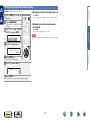
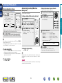
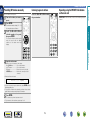
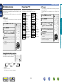
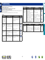
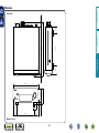
Preparations
Operations
DRA-F109
STEREO RECEIVER
CD
Informations
Owner’s Manual
nSAFETY PRECAUTIONS
CAUTION:
TO REDUCE THE RISK OF ELECTRIC SHOCK, DO NOT REMOVE
COVER (OR BACK). NO USER-SERVICEABLE PARTS INSIDE.
REFER SERVICING TO QUALIFIED SERVICE PERSONNEL.
The exclamation point within an equilateral triangle is intended
to alert the user to the presence of important operating
and maintenance (servicing) instructions in the literature
accompanying the appliance.
WARNING:
TO REDUCE THE RISK OF FIRE OR ELECTRIC SHOCK, DO NOT
EXPOSE THIS APPLIANCE TO RAIN OR MOISTURE.
HOT SURFACE. DO NOT TOUCH.
Hot
surface
mark
The top surface over the internal heat sink may become hot
when operating this product continuously.
Do not touch hot areas, especially around the “Hot surface
mark” and the top panel.
13.Refer all servicing to qualified service personnel.
Servicing is required when the apparatus has been damaged in any way,
such as power-supply cord or plug is damaged, liquid has been spilled or
objects have fallen into the apparatus, the apparatus has been exposed to
rain or moisture, does not operate normally, or has been dropped.
14.Batteries shall not be exposed to excessive heat such as sunshine, fire or
the like.
CAUTION:
To completely disconnect this product from the mains, disconnect the plug
from the wall socket outlet.
The mains plug is used to completely interrupt the power supply to the unit
and must be within easy access by the user.
CD
I
DENON EUROPE
Division of D&M Germany GmbH
An der Kleinbahn 18, Nettetal,
D-41334 Germany
A NOTE ABOUT RECYCLING:
This product’s packaging materials are recyclable and can
be reused. Please dispose of any materials in accordance
with the local recycling regulations.
When discarding the unit, comply with local rules or
regulations.
Batteries should never be thrown away or incinerated
but disposed of in accordance with the local regulations
concerning battery disposal.
This product and the supplied accessories, excluding the
batteries, constitute the applicable product according to the
WEEE directive.
Informations
CAUTION:
Read these instructions.
Keep these instructions.
Heed all warnings.
Follow all instructions.
Do not use this apparatus near water.
Clean only with dry cloth.
Do not block any ventilation openings.
Install in accordance with the manufacturer’s instructions.
Do not install near any heat sources such as radiators, heat registers,
stoves, or other apparatus (including amplifiers) that produce heat.
9. Protect the power cord from being walked on or pinched particularly at
plugs, convenience receptacles, and the point where they exit from the
apparatus.
10. Only use attachments/accessories specified by the manufacturer.
11. Use only with the cart, stand, tripod, bracket, or table
specified by the manufacturer, or sold with the apparatus.
When a cart is used, use caution when moving the cart/
apparatus combination to avoid injury from tip-over.
12. Unplug this apparatus during lightning storms or when
unused for long periods of time.
We declare under our sole responsibility that this product, to which this
declaration relates, is in conformity with the following standards:
EN60065, EN55013, EN55020, EN61000-3-2 and EN61000-3-3.
Following the provisions of Low Voltage Directive 2006/95/EC and EMC
Directive 2004/108/EC, the EC regulation 1275/2008 and its frame work
Directive 2009/125/EC for Energy-related Products (ErP).
Operations
The lightning flash with arrowhead symbol, within an equilateral
triangle, is intended to alert the user to the presence of
uninsulated “dangerous voltage” within the product’s enclosure
that may be of sufficient magnitude to constitute a risk of
electric shock to persons.
1.
2.
3.
4.
5.
6.
7.
8.
•DECLARATION OF CONFORMITY
Preparations
CAUTION
RISK OF ELECTRIC SHOCK
DO NOT OPEN
IMPORTANT SAFETY
INSTRUCTIONS
nCAUTIONS ON INSTALLATION
nNOTES ON USE
z
z
z
Wall
zzFor proper heat dispersal, do not install this unit in a confined
space, such as a bookcase or similar enclosure.
•More than 0.3 m is recommended.
•Do not place any other equipment on this unit.
Informations
CD
z
Operations
•Avoid high temperatures.
Allow for sufficient heat dispersion when installed in a rack.
•Handle the power cord carefully.
Hold the plug when unplugging the cord.
•Keep the unit free from moisture, water, and dust.
•Unplug the power cord when not using the unit for long periods of time.
•Do not obstruct the ventilation holes.
•Do not let foreign objects into the unit.
•Do not let insecticides, benzene, and thinner come in contact with the unit.
•Never disassemble or modify the unit in any way.
•Ventilation should not be impeded by covering the ventilation openings
with items, such as newspapers, tablecloths or curtains.
•Naked flame sources such as lighted candles should not be placed on
the unit.
•Observe and follow local regulations regarding battery disposal.
•Do not expose the unit to dripping or splashing fluids.
•Do not place objects filled with liquids, such as vases, on the unit.
•Do not handle the mains cord with wet hands.
•When the switch is in the OFF (STANDBY) position, the equipment is not
completely switched off from MAINS.
•The equipment shall be installed near the power supply so that the power
supply is easily accessible.
•Do not keep the battery in a place exposed to direct sunlight or in places
with extremely high temperatures, such as near a heater.
Preparations
WARNINGS
II
Preparations
Getting Started
Thank you for purchasing this DENON product. To ensure proper operation, please read this owner’s manual carefully before using the product.
After reading them, be sure to keep them for future reference.
Contents
Getting Started··············································································1
Accessories···················································································2
Features·························································································2
Cautions on handling·····································································2
Connections····················································································4
Connecting the speakers·······························································4
Connecting a CD player·································································5
Connecting a network audio player···············································5
Connecting a TV············································································5
Connecting an antenna··································································6
Connecting the power cord···························································7
Basic operation···············································································9
Preparations···················································································9
Setting the current time (24-Hour display)···································10
Operations during playback·························································11
Listening to FM broadcasts·························································12
Listening to DAB/DAB+ (for UK model only)·······························16
Advanced operation·····································································18
Setting the alarm·········································································18
Convenient functions···································································20
About system functions······························································21
Device supporting system connections (sold separately)············21
What you can do with the system functions·······························21
Making system connections························································21
System functions·········································································21
Part names and functions···························································23
Front panel···················································································23
Display·························································································23
Rear panel····················································································23
Remote control unit·····································································24
Explanation terms········································································26
Troubleshooting···········································································27
Specifications···············································································28
1
Informations
CD
Informations···········································································22
Operations
Preparations··············································································3
Operations·················································································8
Accessories
Features
qGetting Started......................................................................... 1
wCD-ROM (Owner’s manual)..................................................... 1
eSafety Instructions................................................................... 1
rService network list.................................................................. 1
tq Power cord: for continental model only............................... 1
w Power cord: for UK model only............................................ 1
t
q
t
w
y
High quality amplifier
Equipped with 65 W + 65 W (4 Ω) high-quality amplifier circuits.
This design lets you hear the details of music on a powerful
dynamic foundation.
“Simple & Straight” circuit design for sound
purity and free of coloration
DENON’s popular Hi-Fi products give you high sound quality based
on the “simple & Straight” concept. Circuitry is uncomplicated,
signal paths are short, and all adverse influences on sound quality
have been minimized.
Digital input for Network player / CD Player / TV
DRA-F109 has the digital audio interface which can receive HighResolution signal 24 bit / 192 kHzz.
You can enjoy High-Resolution sound by connecting the network
player that supported to playback 24 bit / 192 kHzz Audio file.
zzThis unit is not compatible with DIGITAL IN (OPTICAL).
i
o
The two-line display on the front panel makes setting the timer
very easy, and lets you check the time when the system is turned
on and off.
Auto Standby mode for save the energy
CD
2
•Power is supplied to some of the circuitry even when the unit is
set to the standby mode. When going on vacation or leaving home
for long periods of time, be sure to unplug the power cord from the
power outlet.
•About condensation
If there is a major difference in temperature between the inside of
the unit and the surroundings, condensation (dew) may form on
the operating parts inside the unit, causing the unit not to operate
properly.
If this happens, let the unit sit for an hour or two with the power
turned off and wait until there is little difference in temperature
before using the unit.
•Cautions on using mobile phones
Using a mobile phone near this unit may result in noise. If that
occurs, move the mobile phone away from this unit when it is in use.
•Moving the unit
Turn off the power and unplug the power cord from the power
outlet. Next, disconnect the connection cables to other system units
before moving the unit.
•About care
•Wipe the cabinet and control panel clean with a soft cloth.
•Follow the instructions when using a chemical cleaner.
•Benzene, paint thinner or other organic solvents as well as
insecticide may cause material changes and discoloration if brought
into contact with the unit, and should therefore not be used.
Informations
Two line FL display for easy reading, setup, and
broadcasting information
•Before turning the power on
Check once again that all connections are correct and that there are
no problems with the connection cables.
Operations
yRemote control unit (RC-1163)................................................. 1
uR03/AAA batteries.................................................................... 2
iFM indoor antenna (for continental model only)....................... 1
oDAB/FM indoor antenna (for UK model only)........................... 1
Cautions on handling
Preparations
Check that the following parts are supplied with the product.
Preparations
Here, we explain the connection methods for this unit.
Preparations
Preparations
F Connecting the speakers vpage 4
F Connecting a network audio player vpage 5
F Connecting a TV vpage 5
Operations
F Connecting a CD player vpage 5
F Connecting an antenna vpage 6
CD
3
Informations
F Connecting the power cord vpage 7
For system connections, also see the section “Making system
connections” (vpage 21).
NOTE
Speakers
(L)
Carefully check the left (L) and right (R) channels and + (red) and –
(black) polarities on the speakers being connected to the DRA-F109,
and be sure to interconnect the channels and polarities correctly.
(R)
off about 10 mm of sheathing from
1 Peel
the tip of the speaker cable, then either
twist the core wire tightly or terminate it.
IN
Cables used for connections
Connecting the speaker cables
Subwoofer
with built-in
amplifier
w
q
w
q
Audio cable (sold separately)
the speaker terminal
2 Turn
counterclockwise to loosen it.
the speaker cable’s core wire to
3 Insert
the hilt into the speaker terminal.
Speaker cable
the speaker terminal clockwise to
4 Turn
tighten it.
Optical cable
Audio cable
NOTE
L
L
R
R
When using an SC-F109 (speaker system, sold separately), we
recommend using the receiver’s optimizing filter.
Signals adjusted for the SC-F109’s properties are output.
(vpage 20 “Convenient functions”).
Coaxial digital cable
CD
4
•Disconnect this unit’s power plug from the power outlet before
connecting the speakers. Also, turn off the subwoofer.
•Use speakers with an impedance of 4 to 16 Ω. The protection
circuit may be activated if speakers with an impedance other
than specified are used.
•Connect the speaker cables so they do not stick out of the
speaker terminals. The protection circuit may be activated if the
wires touch the rear panel or if the + and – sides touch each
other (vpage 26 “Protection circuit”).
•Never touch the speaker terminals while the power supply is
connected. Doing so could result in electric shock.
Informations
Subwoofer cable
Operations
•Do not plug in the power cord until all connections have been
completed.
•When making connections, also refer to the operating instructions of
the other components.
•Be sure to connect the left and right channels properly (left with left,
right with right).
•Do not bundle power cords together with connection cables. Doing
so can result in humming or noise.
Connecting the speakers
Preparations
Connections
Connecting a CD player
Connecting a network audio player
AUDIO
COAXIAL
OUT
AUDIO
OUT
L
R
L
AUDIO
COAXIAL
OUT
AUDIO
OUT
L
R
AUDIO
OPTICAL
OUT
AUDIO
OUT
L
R
R
L
or
R
R
L
R
or
R
L
R
Operations
L
or
L
Preparations
Network
audio player
CD Player
Connecting a TV
•Select the connector to use and connect the device.
•To listen to TV audio through this unit, use the optical digital
connection.
TV
Informations
When connecting the DRA-F109 and DCD-F109 (CD player, sold
separately), make system connections.
This enables operation using the DRA-F109’s remote control
unit and the various system functions.
(vpage 21 “About system functions”)
To connect DCD-F109 to this unit, use a coaxial digital cable.
CD
When connecting the DRA-F109 and DNP-F109 (Network audio
player, sold separately), make system connections.
This enables operation using the DRA-F109’s remote control
unit and the various system functions.
(vpage 21 “About system functions”)
To connect DNP-F109 to this unit, use a coaxial digital cable.
5
NOTE
•Other digital audio signals than 2 channel linear PCM cannot be input
through DIGITAL IN (OPTICAL) connector of this unit.
•When you try to input digital audio signals other than 2 channel linear
PCM to this unit, set the digital audio output setting of the TV to 2
channel PCM. For details, see the operating instructions of the TV.
Connecting an antenna
DAB (for UK model only)
•Connect the FM antenna included with the unit to enjoy listening to
radio broadcasts.
•After connecting the antenna and receiving a broadcast signal
(vpage 12 “Listening to FM broadcasts”), use tape to fix the
antenna in a position where noise is the lowest.
nnInstalling the DAB indoor antenna
DAB station reception (vpage 16).
Preparations
FM (for continental model only)
DAB/FM indoor antenna
(Supplied)
FM indoor antenna
(supplied)
Operations
Informations
NOTE
•Do not connect two FM antennas simultaneously.
•If you are unable to receive a good broadcast signal, we recommend
installing an outdoor antenna. Inquire at the retail store where you
purchased the unit for details.
CD
6
Connecting the power cord
nnFor continental model only
Preparations
Wait until all connections have been completed before connecting the power cord.
nnFor UK model only
Connecting to the AC OUTLET
UNSWITCHED (Total capacity: 100 W (0.43 A)):
Make sure the total power consumption of the connected
devices does not exceed 100 W (0.43 A).
Operations
To household power outlet
(AC 230 V, 50/60 Hz)
Power cord (Supplied)
To household power outlet
(AC 230 V, 50/60 Hz)
Power cord (Supplied)
CD
7
Informations
NOTE
•Insert the AC plugs securely. Incomplete connections could cause
noise.
Do not unplug the power cord before the power indicator turns off
and the DRA-F109 enters Standby mode.
•Only use the supplied power cord.
•Be sure the power cord is unplugged from the power outlet before
connecting or disconnecting it to the AC IN.
•The AC outlet is for use with audio components. Do not use it to
connect hair dryers or any equipment other than audio components.
Operations
Here, we explain functions and operations that let you make better use of this unit.
F Advanced operation vpage 18
F About system functions vpage 21
Operations
F Basic operation vpage 9
Preparations
Operations
Informations
CD
8
nn Turning the power on (vpage 9)
nn Setting the current time (24-Hour display)
(vpage 10)
Press POWER X.
•The power turns on. Press again to set the
power to standby.
•Power indicator
Normal standby........................Off
Power on..................................Green
Alarm standby..........................Orange
•When the power is turned on, the function that was being used
when the power was last turned off is selected (vpage 20
“Last function memory”).
•The receiver switches to the low power consumption mode about
30 minutes after it is set to standby.
nn Advanced operation (vpage 18)
nn About system functions (vpage 21)
When the power is in the standby mode, pressing one of the following
buttons also turns this unit on.
•X or PRESET CALL on the main unit
•TUNER, ANALOG IN or DIGITAL IN on the remote control unit
NOTE
Power continues to be supplied to some of the circuitry even when the
power is in the standby mode. When leaving home for long periods of
time or when traveling, unplug the power cord from the power outlet.
CD
9
nnCompletely turning off the power
Unplug the power cord from the wall outlet.
•Note that the time setting is cleared when the power cord is
unplugged from the outlet.
•The settings made for the various functions may be cleared if the
power cord is left unplugged from a power outlet for an extended
period of time.
Informations
nn Listening to FM broadcasts (vpage 12)
nn Listening to DAB/DAB+ (for UK model only)
(vpage 16)
Turning the power on
Operations
nn Selecting the input source (vpage 11)
nn Adjusting the master volume (vpage 11)
nn Adjusting the tone (vpage 11)
nn Turning off the sound temporarily (vpage 11)
nn Switching the brightness of the display
(vpage 11)
Preparations
Preparations
Basic operation
Setting the current time (24-Hour display)
1
2 Press SYSTEM SETUP.
Press POWER X to turn the
power on.
Various types of setting menus are
displayed.
Press CLOCK.
Press once more and the display returns to its original condition.
nnChecking the current time when the power is
set to standby
Press CLOCK.
The current time is displayed for 10 seconds.
NOTE
SETUP
CLOCK SETUP
The time cannot be set when in the standby mode. Turn on the power
first.
4 Use ui to set the “hours”.
CLOCK
SETUP
10:00
Informations
5 Press ENTER or p.
6 Use ui to set the “minutes”.
The “minutes” display flashes.
CLOCK
Operations
Use ui to select “CLOCK
3 SETUP”,
then press ENTER.
nnChecking the current time when the power is on
Preparations
GExampleH Setting the current time to 10:15 am
SETUP
10:15
7 Press ENTER or p.
The current time is set, and the normal display reappears.
CD
10
Operations during playback
Adjusting the tone
Turning off the sound temporarily
Press TUNER, ANALOG IN or DIGITAL
INz to select the input source.
SDB TONE to select the
1 Press
tone parameter to be adjusted.
Press MUTE :.
The desired input source can be selected
directly.
SDB
BASS
S. DIRECT
OPTICAL
NETWORK
CD
•To make other tone adjustments at this time, press SDB TONE.
•If no operation is performed for 5 seconds, the adjustment is
retained and the normal display reappears.
nnUsing the knob on the main unit
ANALOG IN:2
DABz
ANALOG IN:1
zzFor UK model only
Adjusting the master volume
Use VOLUME df to adjust the
volume.
The volume level is displayed.
–
59
,
MAX
You can also do this by turning VOLUME on the main unit.
CD
–
OFF
–10dB – +10dB
:Adjusts the treble sound.
Press DIMMER.
Bright
Dim
Off
Dark
•The display’s brightness switches each time
the button is pressed.
–10dB – +10dB
GVariable rangeH
BALANCE :Adjusts the left/right volume balance.
+L6 – CENTER – +R6
GVariable rangeH
Press o when you want to adjust the left channel, p
when you want to adjust the right channel.
S.DIRECT :The tone is not adjusted.
GDefault settingsH
•SDB··············································· OFF
•BASS··············································0dB
•TREBLE··········································0dB
•BALANCE······························· CENTER
GVariable rangeH
00
TREBLE
ON
:Adjusts the bass sound.
GVariable rangeH
FM
Switching the brightness of the display
:Emphasize the bass sound (Super Dynamic Bass).
GSelectable modesH
BASS
To cancel, press MUTE : again.
(The mute mode is also canceled when VOLUME df is pressed.)
SDB and BASS can be set simultaneously.
11
When the system connection is established, the brightness switches
on all devices.
Informations
DIGITAL IN:OPT
SDB
Turn SOURCE.
•Every time you turn SOURCE, the input source switches in the
following order.
CD/USB
BALANCE
Use o p to adjust the SDB,
2 BASS,
TREBLE or BALANCE.
You can also use the following operation to select an input
source.
NETWORK/USB
TREBLE
Operations
zzEach time you press DIGITAL IN, the input source switches as
follows.
The “MUTE ON” is displayed.
Preparations
Selecting the input source
Listening to FM broadcasts
Connect the antenna beforehand (vpage 6).
1
Press TUNER to
reception band.
select
the
•When “FM AUTO” is selected:
“AUTO” is displayed.
•When “FM MONO” is selected:
“MONO” is displayed.
FM AUTO
FM MONO
zzUK model only
•When the reception band mode is set to “FM AUTO”, the “ST”
indicator lights when a stereo broadcast is tuned in.
2 Use TUNE –, TUNE + to select the reception band.
Up to 40 stations can be preset.
nnAuto presetting with the remote control unit
1
Use ui to select “FM AUTO
2 PRESET”,
then press ENTER or
Press SEARCH.
Press ENTER while
3 ENTER”
is flashing.
Broadcast
stations
automatically.
“PRESS
are
preset
Press TUNER or 2.
Broadcast stations whose antenna signal are weak cannot be preset
automatically. If you wish to preset such stations, tune them in
manually.
When the auto presetting operation is performed, the new presettings
overwrite the previous presettings.
CD
3 Input the station name.
Names of up to 8 characters can be input.
•0 – 9 button....................... Selects the character.
•u, i button..................... Selects the character.
•p button........................... Moves the cursor to the right.
•CLEAR button.................... Deletes the currently selected
character.
•Characters that can be input.
4 Press ENTER.
The characters you have input are entered.
•To give names to other stations, repeat steps 1 to 4.
NOTE
Press TUNE –, TUNE +.
The display switches to the station
name input display.
A ~ Z, 0 ~ 9, ^ ’ ( ) * + , - . / = (space)
nnCanceling auto presetting
nnTo stop auto tuning
in the preset channel you
1 Tune
want to name.
2 Press ENTER twice.
12
Informations
•If the function is set to something other than “FM”, press TUNER to
switch the function to “FM”.
•If the signal is weak and stable stereo reception is not possible,
select “FM MONO” to receive in monaural.
Press and hold in TUNE –, TUNE + to tune in stations automatically.
•Stations whose signal is weak cannot be tuned in.
•In the DAB mode, tuning only moves to receivable stations, so
auto tuning is not possible.
Names of up to 8 characters can be input.
p.
When a station is received, the “TUNED” indication will light.
nnTo tune automatically
nnGiving station names to preset channels
Operations
DABz
Automatically presetting FM stations
(Auto preset)
Preparations
Tuning in broadcast stations
Listening to FM broadcasts
Listening to preset stations
Up to 40 stations can be preset.
Use 0 – 9, +10 or CH –, CH + to select
the preset number.
in the station you want to
1 Tune
preset.
2 Press ENTER.
Operating using the PRESET CALL buttons
on the main unit
PRESET CALL on the main unit can be used for switching the preset
channel.
Preparations
Presetting FM stations manually
The minimum number display “P– –” for
the unregistered preset flashes.
Operations
0 – 9, +10 or CH –, CH + to
3 Use
select the number to be preset,
then press ENTER.
The reception frequency and reception
mode are preset and the display
switches to the station name input
display.
Informations
4 Input the station name.
Names of up to 8 characters can be input.
•0 – 9, +10 button................ Selects the character.
•u, i button..................... Selects the character.
•p button........................... Moves the cursor to the right.
•CLEAR button.................... Deletes the currently selected
character.
•Characters that can be input.
A ~ Z, 0 ~ 9, ^ ’ ( ) * + , - . / = (space)
•If you do not want to input a station name, press ENTER without
inputting anything else.
•If you make a mistake when inputting, perform the procedure
again. Whatever was previously input is overwritten.
5 Press ENTER.
The characters you have input are entered.
•To give names to other stations, repeat steps 1 to 4.
CD
13
Listening to FM broadcasts
Program Type (PTY)
RDS (works only on the FM band) is a broadcasting service which
allows a station to send additional information along with the regular
radio program signal.
The following four types of RDS information can be received with this
unit:
PTY identifies the type of RDS program.
The program types and their displays are as follows:
nnRDS search
Use this function to automatically tune to FM stations that provide
the RDS service.
p.
EASY M
Easy Listening
Music
LIGHT M
CLASSICS
OTHER M
Light Classical
Serious Classical
Other Music
WEATHER
FINANCE
Weather
Finance
CHILDREN
Children’s
program
SOCIAL
RELIGION
PHONE IN
TRAVEL
LEISURE
JAZZ
COUNTRY
NATION M
OLDIES
FOLK M
DOCUMENT
Social Affairs
Religion
Phone In
Travel
Leisure
Jazz Music
Country Music
National Music
Oldies Music
Folk Music
Documentary
•If no RDS station is found, “NO STATION”
is displayed.
Viewing information during reception
Press INFO while receiving a RDS to display
the information currently being broadcast.
*1
*2
PS
RT
PTY
CT
*1Frequency
*2 Program service name
•If a station name is entered, it is displayed
CD
p.
Use ui to call out the desired
4 program
type.
5 Press o p.
Automatically begin the PTY search
operation.
•If no program of the specified type is found,
“NO STATION” is displayed.
Automatically begin the RDS search
operation.
Freq.
1 Press TUNER to select “FM”.
2 Press SEARCH.
ui to select “PTY
3 Use
SEARCH”, then press ENTER or
14
Informations
4 Press o p.
News
Current Affairs
Information
Sports
Education
Drama
Culture
Science
Varied
Pop Music
Rock Music
Use this function to find RDS stations broadcasting a designated
program type (PTY).
For a description of each program type, refer to “Program Type
(PTY)”.
Operations
1 Press TUNER to select “FM”.
2 Press SEARCH.
ui to select “RDS
3 Use
SEARCH”, then press ENTER or
NEWS
AFFAIRS
INFO
SPORT
EDUCATE
DRAMA
CULTURE
SCIENCE
VARIED
POP M
ROCK M
nnPTY search
Preparations
RDS (Radio Data System)
Listening to FM broadcasts
RT (Radio Text)
TP identifies programs that carry traffic announcements.
This allows you to easily find out the latest traffic conditions in your
area before leaving home.
RT allows RDS stations to send text messages that appear on the
display.
nnTP search
Use this function to find RDS stations broadcasting traffic programs
(TP stations).
Automatically begin the TP search
operation.
The operations described below selecting “RDS Search” will not
function in areas in which there are no RDS broadcasts.
CT (Clock Time)
Use this to correct the time of the clock on the unit.
q During CT reception, press SYSTEM SETUP.
The “AUTO Adj mm:ss” is displayed.
wPress ENTER to set.
The “RDS
mm:ss” is displayed.
•The time on the set’s internal clock is updated to the currently
displayed “CT” time.
Do not operate any buttons while the time is being updated. If buttons
are operated, CT reception is not possible and the time is not updated.
CD
15
Informations
•“NO STATION” is displayed when there is
no traffic information broadcast station.
NOTE
Operations
1 Press TUNER to select “FM”.
2 Press SEARCH.
Use ui to select “TP SEARCH”,
3 then
press the ENTER or p.
4 Press o p.
•When the RT mode is turned on while an RDS radio station not
offering an RT service is tuned in, “NO TEXT” is displayed on the
display, then the mode automatically switches to the PS mode.
•In the same way, the mode automatically switches to the PS mode
when the RT service is finished. In this case, the mode automatically
switches from the PS mode back to the RT mode when an RT
broadcast is resumed.
•The RT mode cannot be set in the FM stations not offering RDS
broadcasts.
Preparations
TP (Traffic Program)
Listening to DAB/DAB+ (for UK model only)
nnAbout DAB+
•When a DAB operation is performed for the
first time after purchase, auto scanning is
performed automatically.
TUNE +, – to select the
2 Press
desired broadcast station.
•The broadcast stations are displayed in the
order in which they were scanned.
steps 1 to 2 under
1 Perform
“Tuning in DAB stations” to tune
in a DAB station.
2 Press INFO.
•The display switches as shown below each
time the button is pressed.
DAB stations can be stored in the preset memory and played in the
same way as FM stations.
•“Presetting FM Stations Manually”
•“Listening to Preset Stations”
•Up to 40 stations can be preset (in addition to FM stations).
q Data Label Segment :
Text data included in the broadcast is scrolled.
Auto scanning broadcast stations
e Program Type :
The category of the tuned in station is displayed.
w Station Name :
The service station name is displayed.
Connect the antenna beforehand.
1
Press ENTER while
2 ENTER”
is flashing.
Press SEARCH
reception.
during
DAB
“PRESS
The receiver searches for receivable
DAB stations.
r Ensemble Name :
The ensemble name is displayed.
tFrequency:
The frequency is displayed.
y Signal Quality :
The reception signal sensitivity is displayed (0 to 8).
•If the reception signal sensitivity is 7 or greater, the
program can be received without noise.
u Audio Information :
The mode of the currently tuned in station and its bit rate
are displayed.
i Data and Time :
The current date and time are displayed.
•When SYSTEM SETUP is pressed, the set’s internal clock
is updated to the currently displayed time.
CD
16
Informations
•The main difference between DAB and DAB+ is the type of audio
codec used.
DAB: MPEG2
DAB+: MAEG4 (AAC)
•The DRA-F109 can receive both DAB and DAB+ broadcasts.
1 Press TUNER to select “DAB”.
Switching the reception information for the
currently tuned in DAB station
Operations
•Since the DAB system is broadcasted in digital format, DAB
system can supply crystal-clear audio and stable reception even
in mobile objects. DAB is a new generation radio which can
provide data service and supplementary multi-media services.
•DAB broadcasts multiple services under one Ensemble that are
called service components.
•Each component contains inherent programmes; news, music,
sports, and many more.
•Each Ensemble and service component has its label, and users
can recognize a current broadcasting station and service contents
by using the label.
•The main service component is broadcast as Primary while the
others are broadcast as Secondary.
•Also rich character information is serviced through Dynamic
Labels; song title, artist composer etc.
Tuning in DAB stations
Preparations
nnAbout DAB (Digital Audio Broadcasting)
Listening to DAB/DAB+ (For UK model only)
DAB Initialize
Press SYSTEM SETUP during
1 DAB
reception.
Use ui to select “DAB SETUP”,
2 then
press ENTER or p.
ui to select “item”, then
3 Use
press ENTER.
When the “DAB Initialize” procedure is performed, all the preset
memory settings for the stations and DABs are reset.
The reception sensitivity of the currently
tuned in frequency is displayed.
•The program can be received without noise when the cursor
move to the right of the sensitivity display.
Station Order
The service list is created with the auto scan
function.
MULTIPLEX
(In order of frequency)
DAB Version
Off
1/2
ALPHANUMERIC
(In alphabetical order)
1
ui to select “DAB SETUP”, then press the
2 Use
ENTER or p.
Use ui to select “DAB INITIALIZE”, then press
3 the
ENTER or p.
4 Press ENTER.
•Once initialization is completed, auto scanning is performed
automatically.
The DAB module’s version is displayed.
CD
17
Informations
DRC
(Dynamic Range Control)
during
Operations
Tuning Aid
Press SYSTEM SETUP
1 DAB
reception.
Preparations
Making the DAB settings
nn Basic operation (vpage 9)
Setting the alarm
The everyday alarm, once alarm and sleep timer can be set.
nn Setting the alarm (vpage 18)
nn Convenient functions (vpage 20)
nn About system functions (vpage 21)
Alarm order of priority
If the current time is not set, enter alarm setting mode to get time
setting mode.
Setting the alarm
1 Press SYSTEM SETUP.
Use ui to select “ALARM
2 SETUP”,
then press ENTER or p.
ui to select the alarm
3 Use
mode, then press ENTER or p.
MODE SELECT
ONCE ALARM
ONCE
CD
EVERYDAY
18
SELECT
iPod/USB
TUNER
ANALOG IN:1
(CD)
CD
iPod/USB
INTERNET RADIO
(NET)
ANALOG IN:2
DIGITAL IN:OPT
Only when the “TUNER” function is selected
ui to select the preset number, then press
5 Use
ENTER or p.
•When no name has been registered for the selected preset
number, the program service or frequency appears after the preset
number is displayed.
Use ui to select “hours” for the alarm start time,
6 then
press ENTER or p.
ON
TIME
10:00>
00:00
ui to select “minutes” for the alarm start time,
7 Use
then press ENTER or p.
ON
TIME
10:30>
00:00
v See overleaf
Informations
•Everyday alarm (“EVERY DAY”)
Playback starts and stops (the power turns off) at the set times each
day.
•Once alarm (“ONCE”)
Playback starts and stops (the power turns off) once only at the set
times.
SOURCE
CD
Operations
The order of priority when the times set for the different alarms
overlap is as follows:
1. Sleep timer
2. Once alarm
3. Everyday alarm
4 Use ui to select the source, then press ENTER or p.
Preparations
Advanced operation
Setting the alarm
OFF TIME
10:30>
11:00
Use ui to select “minutes” for the alarm stop time,
9 then
press ENTER or p.
10
Use o p to select “ON” or “OFF” for the alarm, then
press ENTER.
•The
indicator lights and the alarm setting is entered.
•The alarm settings are displayed for 3 seconds.
ONCE ALARM ON
EVERYDAY
0OFF1
11
Press POWER X to set the power to standby.
Alarm standby mode is set, and the power indicator lights
orange.
CD
“EVERYDAY”.
rUse o p to select “ON” or “OFF”
for the alarm, then press ENTER. The
alarm settings are displayed after this.
•When set to “OFF”, time operation is disabled, but the alarm
settings remain unchanged.
nnTo check the alarm settings
qPress SYSTEM SETUP.
wUse ui to select “ALARM ON/OFF” , then press ENTER.
eWhen “ON” is displayed for the alarm setting, press ENTER.
Setting the sleep timer
Use this function to automatically switch the power to the standby
mode after a specific amount of time (minutes).
The sleep timer can be set to up to 90 minutes, in steps of 10 minutes.
Press SLEEP during playback and select the setting time.
SLEEP 90min
SLEEP OFF
80
10
70
20
60
30
50
40
•After about 5 seconds, the setting is entered and the display
returns to as it was before.
nnCanceling the sleep timer
Either press SLEEP to select “SLEEP
OFF” or press POWER X.
The alarm settings are displayed for 3 seconds.
nnTo change the alarm settings
Perform the operations at “Setting the alarm” (vpage 18).
nnTo change the setting while setting the alarm
Press o.
The setting returns to the previous step. Display the setting you
want to change, then make the desired setting.
19
nnTo check the time remaining until the sleep
timer is activated
Press SLEEP.
Informations
ONCE ALARM0ON 1
EVERYDAY
OFF
qPress SYSTEM SETUP.
wUse ui to select “ALARM ON/OFF”,
then press ENTER.
eUse ui to select “ONCE” or
Operations
OFF TIME
10:30>
11:30
nnSetting the alarm to on or off
Preparations
ui to select “hours” for the alarm stop time,
8 Use
then press ENTER or p.
Convenient functions
The receiver’s speaker output signal properties are set to be optimal
for the SC-F109.
ENTER or p.
3 Use ui to select “ON”, then press the ENTER or p.
The setting is entered.
Last function memory
When this unit is in the stop state and there is no input signal and
operation for 30 minutes, it automatically enters the standby mode.
For the input source “ANALOG IN:1” and “ANALOG IN:2” only, when
no operation is performed for eight hours, this unit automatically
enters the standby mode.
•The default setting for the Auto Standby mode is “ON”.
This stores the settings as they were directly before the standby
mode was set.
When the power is turned back on, the settings are restored to as
they were directly before the standby mode was set.
1 Press SYSTEM SETUP.
Use ui to select “AUTO
2 STANDBY”,
then press ENTER
or p.
Operations
1 Press SYSTEM SETUP.
ui to select “SPK
2 Use
OPTIMISE”, then press the
Auto standby
Preparations
Setting the optimizing filter for the SC-F109
speaker system (sold separately)
3 Use ui to select “ON”, then press ENTER or p.
The setting is entered.
NOTE
CD
20
Informations
In the following situations, the Auto standby function does not operate.
•When the source is “TUNER”.
NOTE
Do not connect any of the past models to this unit with a
system cable because they are incompatible.
Device supporting system
connections (sold separately)
What you can do with the system
functions
nnThe DCD-F109 and DNP-F109 can be operated
using the receiver’s remote control unit
(vpage 24 “Buttons for operating components connected by
system cable”)
NOTE
Be sure to plug the DRA-F109’s power cord into a wall power outlet.
Auto power on function
When you press 1/3, INTERNET
RADIO, ONLINE MUSIC, MUSIC
SERVER, iPod/USB (NETWORK),
CD, iPod/USB (CD), or FAVORITE
CALL, the corresponding device
is turned on and the source
automatically switches on DRA-F109
accordingly.
•When you press 1/3, the previously
selected source is played back.
DRA-F109 (This unit)
Auto function
To a wall power
outlet
System cable
(Included with the
DCD-F109)
DCD-F109
When INTERNET RADIO, ONLINE
MUSIC, MUSIC SERVER, iPod/
USB (NETWORK), CD, iPod/USB
(CD) FAVORITE CALL or NETWORK
SETUP is pressed, the DRA-F109’s
source switches automatically.
•The currently playing source stops.
nnAuto power on function
(vpage 21 “System functions”)
System cable
(Included with the
DNP-F109)
nnAuto function
(vpage 21 “System functions”)
DNP-F109
Alarm function
Playback can be performed at a set time using the DRAF109’s alarm function.
nnAlarm function
(vpage 21 “System functions”)
•See “Setting the alarm” (vpage 18) for details.
nnAuto standby function
(vpage 21 “System functions”)
Auto standby function
When the auto standby function is set to ON for any of DRA-F109,
DCD-F109 or DNP-F109, the auto standby function is enabled for the
entire F109 system.
For the auto standby function, see page 20.
CD
21
Informations
When system connections are made between the DRAF109, DCD-F109 (CD player, sold separately) and DNP-F109
(Network audio player, sold separately), the operations
described below can be performed.
In addition to connection of the audio cables, also connect
the system cable.
Also, connect the power cord of the DCD-F109 (CD player,
sold separately) to the AC outlet on the back of the
receiver (DRA-F109).
Connect the power cord of DNP-F109 (Network audio
player, sold separately) to the AC outlet behind DCD-F109
(CD player, sold separately).
System functions
Operations
DCD-F109 (CD player)
DNP-F109 (Network audio player)
Making system connections
Preparations
About system functions
Informations
Here, we list various information related to this unit.
Please refer to this information as needed.
F Explanation terms vpage 26
Operations
F Part names and functions vpage 23
Preparations
Informations
F Troubleshooting vpage 27
F Specifications vpage 28
CD
22
Informations
F Index vpage 28
Front panel
Preparations
Part names and functions
Rear panel
For buttons not explained here, see the page indicated in parentheses ( ).
For buttons not explained here, see the page indicated in parentheses ( ).
ForUK
UKmodel
modelonly
only
For
q
Operations
q w e r t
y
i
uHeadphones jack (PHONES)
When the headphones are plugged into this
jack, audio will no longer be output from the
connected speakers.
NOTE
q
To prevent hearing loss, do not raise the volume
level excessively when using headphones.
Display
qTone indicators············································ (11)
SDB: Lights when the super dynamic bass
function is set to “ON”.
TONE: Lights when the tone (bass/treble) is
being adjusted.
CD
t
DAB/FM antenna terminal (ANTENNA)
(for UK model only)·········································· (6)
wREMOTE CONNECTOR jack························ (21)
eDigital audio connectors
For buttons not explained here, see the page indicated in parentheses ( ).
e
r
(for continental model only)····························· (6)
w
e
qFM antenna terminal (ANTENNA)
iVOLUME knob············································· (11)
q
w
(DIGITAL IN)··················································· (5)
r t
wTuner reception mode indicators·············· (12)
eInformation display
Various information is displayed here.
rTimer operation indicator
tRemote control signal reception indicator
23
y
u
i
rSubwoofer connector
(SUBWOOFER OUT)······································ (4)
tAnalog audio connectors
(ANALOG IN)·················································· (5)
ySpeaker terminals (SPEAKERS)··················· (4)
uAC inlet (AC IN)·············································· (7)
iAC outlet (AC OUTLET)································· (7)
Informations
qPower operation button (X)························· (9)
wPower indicator············································· (9)
ePRESET CALL button·································· (13)
rSOURCE knob·············································· (11)
tRemote control sensor······························· (26)
yDisplay
u
Remote control unit
Buttons for operating components connected by system cable
For system functions and components that can be operated, see “About system
functions” (vpage 21).
CD operations
Amplifier operations
The buttons below can be operated regardless
of the currently set function.
Q0
o
Q6
Q5
qSLEEP button··············································· (19)
wCLOCK button·············································· (10)
eSOURCE buttons (AMP)····························· (11)
rCursor buttons (uio p)······················ (10, 18)
w
ENTER button········································ (10, 18)
tSYSTEM SETUP button
e
i
y
t
r
q
w
e
Q4
qSOURCE button (CD)
wPlay/Pause button (1/3)
eReverse-skip/Forward-skip buttons
e
rFast-reverse/Fast-forward buttons
r
r
Q3
································································ (10, 18)
ySDB TONE button······································· (11)
uVOLUME buttons (d f)······························ (11)
iMUTE button (:)······································ (11)
oDIMMER button··········································· (11)
Q0POWER button (X)········································ (9)
t
Q2
Tuner operations
The buttons below can be operated when the
function is set to “FM”.
r
y
(6, 7)
tMODE button
yRANDOM button
uREPEAT button
iPROGRAM button
oInformation button (INFO)
Q0CLEAR button
Q1Number buttons (0 – 9,+10 )
Q2Cursor buttons (uio p)
ENTER button
Q3Stop button (2)
Q4SOURCE button (iPod/USB)
Q5DIMMER button
Q6POWER button (X)
qSOURCE button (TUNER)····················· (12, 16)
wPreset channel buttons (CH +, –)················ (13)
eTuning buttons (TUNE +, –)·················· (12, 16)
rSEARCH button··········································· (14)
tInformation button (INFO)···················· (14, 16)
yNumber buttons (0 – 9,+10 )······················· (13)
Q1
Q0
y
u
t
CD
(8, 9)
24
o
i
Informations
u
The buttons below can be operated when the
function is set to “CD/USB”.
Operations
q
w
e
q
Preparations
Buttons for operating the receiver
Remote control unit
The buttons below can be operated when the
function is set to “NETWORK/USB”.
W1
W0
Q9
Q8
q
w
e
r
r
y
u
i
o
Q5
(8, 9)
tFast-reverse/Fast-forward buttons
(6, 7)
yFAVORITE ADD button
uFAVORITE CALL button
iMODE button
oSEARCH button
Q0RANDOM button
Q1REPEAT button
Q2Information button (INFO)
Q3CLEAR button
Q4Number buttons (0 – 9,+10 )
Q5NETWORK SETUP button
Q6Cursor buttons (uio p)
Q4
Q3
Q0
Q1
When this unit is connected to the following device (sold separately)
with a system cable, it transmits the signals from the remote
control unit to the relevant device for performing operations on the
device.
•DCD-F109 (CD player)
•DNP-F109 (Network audio player)
For instructions on system connections, see “About system functions”
(vpage 21).
Informations
Q6
nnOperating components connected to the DRA-F109
by system cable
qINTERNET RADIO button
wSOURCE button (iPod/USB)
ePlay/Pause button (1/3)
rReverse-skip/Forward-skip buttons
ENTER button
Q7Stop button (2)
Q8ONLINE MUSIC button
Q9MUSIC SEVER button
W0DIMMER button
W1POWER button (X)
Q2
CD
Operations
t
Q7
t
nnOperations on the DRA-F109
Preparations
Operations possible by remote control
Network audio player operations
25
Remote control unit
Operating range of the remote control unit
qRemove the remote control
unit’s rear cover.
Point the remote control unit at the remote sensor when operating it.
wSet two R03/AAA batteries in
the battery compartment in the
indicated direction.
Approx. 7 m
30°
30°
NOTE
NOTE
CD
•The set may function improperly or the remote control unit may not
operate if the remote control sensor is exposed to direct sunlight,
strong artificial light from an inverter type fluorescent lamp or
infrared light.
•When using 3D video devices that transmit radio communication
signals (such as infrared signals etc) between the various units (such
as the monitor, 3D glasses, 3D transmitter unit etc), the remote
control unit may not operate due to interference from those radio
communication signals. If this occurs, adjust the direction and
distance of the 3D communication for each unit, and check that the
remote control unit operation is not affected by these signals.
26
P
Protection circuit
This is a function to prevent damage to components within the power
supply when an abnormality such as an overload, excess voltage
occurs or temperature for any reason.
In this unit, the power indicator blinks and the unit enters standby
mode when an abnormality occurs.
S
Speaker impedance
This is an AC resistance value, indicated in Ω (ohms). Greater power
can be obtained with this value smaller.
Informations
•Insert the specified batteries in the remote control unit.
•Replace the batteries with new ones if the set does not operate
even when the remote control unit is operated close to the unit. (The
supplied batteries are only for verifying operation. Replace them
with new batteries at an early date.)
•When inserting the batteries, be sure to do so in the proper direction,
following the q and w marks in the battery compartment.
•To prevent damage or leakage of battery fluid:
•Do not use a new battery together with an old one.
•Do not use two different types of batteries.
•Do not attempt to charge dry batteries.
•Do not short-circuit, disassemble, heat or dispose of batteries in
flames.
•Do not keep the battery in a place exposed to direct sunlight or in
places with extremely high temperatures, such as near a heater.
•If the battery fluid should leak, carefully wipe the fluid off the inside
of the battery compartment and insert new batteries.
•Remove the batteries from the remote control unit if it will not be in
use for long periods.
•Used batteries should be disposed of in accordance with the local
regulations regarding battery disposal.
•The remote control unit may function improperly if rechargeable
batteries are used.
D
Dynamic range
The difference between the maximum undistorted sound level and
the minimum sound level that is discernible above the noise emitted
by the device.
Operations
e Put the rear cover back on.
Explanation terms
Preparations
Inserting the batteries
GRemote control unitH
If a problem should arise, first check the following:
1. Are the connections correct?
2. Is the set being operated as described in the owner’s manual?
3. Are the other components operating properly?
If this unit does not operate properly, check the items listed in the table below. Should the problem persist,
there may be a malfunction.
In this case, disconnect the power immediately and contact your store of purchase.
Symptom
GGeneralH
For stereo
sources, the
positions of the
instruments are
inverted.
Countermeasure
Page
7
•The speaker cables are not •Connect securely.
properly connected.
•The function is not switched to •Switch to the correct function.
the input source you want to
play.
•The volume is set too low.
•Adjust the volume to an
appropriate level.
•The speaker cables are not •Connect securely.
properly connected.
•The input cables are not properly •Connect securely.
connected.
•The left/right balance is off.
•Adjust the left/right balance.
•The connections of the speaker •Check
and
remedy
the
cables or input cables are connections.
inverted.
4
CD
Page
26
26
•Insert the batteries in the
proper direction, following the
polarity marks in the battery
compartment.
•Move the set to a place in which
the remote control sensor will
not be exposed to strong light.
26
Countermeasure
Page
–
26
GTunerH
Symptom
Buzzing noise in
FM broadcasts.
11
11
4
5
11
4, 5
27
Cause
•The antenna cable is not properly •Connect the antenna properly.
connected.
•Noise interference from a nearby •Reposition the equipment or
electronic device equipped with the positions or directions of the
a microprocessor, or the radio connection cables, antenna, etc.
broadcast signal is weak.
6
–
Informations
No sound is
produced from
one side.
Cause
•Connection of the power cord is •Check that the power plugs are
faulty.
securely inserted into the DRAF109’s AC inlet and the wall
power outlet.
Countermeasure
•Replace with new batteries.
•Operate within the specified
range.
•Remove the obstacle.
Operations
Symptom
When the power
is turned on, the
power indicator
does not light
and no sound is
produced.
The power
indicator lights
but no sound is
produced.
Cause
Set does not work •Batteries are worn.
properly when
•You are operating outside of the
remote control
specified range.
unit operated.
•Obstacle between main unit and
remote control unit.
•The batteries are not inserted in
the proper direction, as indicated
by the polarity marks in the
battery compartment.
•The set’s remote control sensor
is exposed to strong light
(direct sunlight, inverter type
fluorescent bulb light, etc.).
Preparations
Troubleshooting
Index
vvA
nn Receiver section
Accessories··························································· 2
Alarm··································································· 18
Dynamic power:
High frequency distortion:
Output terminals:
Input sensitivity:
Reception frequency range:
Reception sensitivity:
FM channel separation:
FM S/N ratio:
FM harmonic distortion:
Tone control:
Frequency response:
vvB
BALANCE···························································· 11
BASS··································································· 11
vvC
nn Clock/Timer section
Power line frequency synchronized method (Within ±60 seconds per month)
Everyday alarm / Once alarm : One system each
Sleep timer : Max. 90 minutes
Clock type:
Timer:
nn General
AC 230 V, 50/60 Hz
48 W
0.3 W (Standby)
Power supply:
Power consumption:
vvD
DAB (Digital Audio Broadcasting)························ 16
DAB/FM indoor antenna········································ 6
Display································································· 23
Display’s brightness············································ 11
Dynamic range···················································· 26
zzFor purposes of improvement, specifications and design are subject to change without notice.
vvF
FM indoor antenna················································ 6
Front panel·························································· 23
vvH
Headphones························································ 23
vvI
Input source························································ 11
vvM
Mute···································································· 11
CD
28
vvS
SDB····································································· 11
S.DIRECT···························································· 11
Sleep timer·························································· 19
Speaker impedance········································· 4, 26
Subwoofer····························································· 4
vvT
Tone···································································· 11
TP········································································ 15
TREBLE······························································· 11
Turning the power on············································ 9
vvV
Volume································································ 11
Informations
Cable
Audio cable························································· 4
Coaxial digital cable············································ 4
Optical cable······················································· 4
Speaker cable····················································· 4
Subwoofer cable················································· 4
Condensation························································ 2
Connection
Antenna······························································ 6
CD player···························································· 5
Network audio player·········································· 5
Power cord························································· 7
Speaker······························································· 4
TV······································································· 5
CT········································································ 15
Current time························································ 10
vvR
RDS····································································· 14
Rear panel··························································· 23
Remote control unit············································ 24
Inserting the batteries······································ 26
RT········································································ 15
Operations
2-channel driving
65 W + 65 W (4 Ω, 1 kHz, T.H.D. 0.7 %)
80 W + 80 W (4 Ω)
0.1 % (Rated output: –3 dB), 4 Ω, 1 kHz
Speaker 4 – 16 Ω
Suited for headphones/stereo headphones
200 mV / 47 kΩ
FM : 87.50 MHz – 108.00 MHz
DAB : BAND III 170 MHz – 240 MHz
FM : 1.2 μV / 75 Ω
DAB : –93 dBm / 50 Ω
30 dB (1 kHz)
Monaural : 74 dB
Stereo : 70 dB
Monaural : 0.3 %
Stereo : 0.4 %
SDB
: 100 Hz + 8 dB
BASS : 100 Hz ± 10 dB
TREBLE : 10 kHz ± 10 dB
10 Hz – 40 kHz (+0.5 dB, –3 dB) (SOURCE DIRECT: ON)
Rated output:
vvP
Playback
DAB·································································· 16
FM···································································· 12
Protection circuit············································· 4, 26
PTY······································································ 14
Preparations
Specifications
Dimensions
Preparations
27.0
22.0
Unit : mm
178.5
11.0
82.0
73.0
190.0
30.0
9.0
30.0
30.0
Weight : 2.6 kg
CD
29
Informations
44.5
283.0
250.0
Operations
250.0
V00
www.denon.com
D&M Holdings Inc.
3510 10002 00AD