1
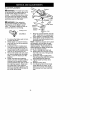
Operator's
Manual
BRUSHCUTI'ER
ATTACHMENT
Model No.
0944.511590
NOT DESIGNED
FOR USE
WITH ELECTRIC
POWERHEADS
DANGER:
Read and follow all Safety Rules and Operating
Instructions before first use of this product.
For answers to your questions about this product: Call 7
am-7 pm, Mon.-Sat., or 10 am-7 pm, Sun.
1-800-235-5878
Sears Canada,
530086421
4/2/01
<.o°,,
Inc., Toronto,
listed are Central Time)
Ontario
M5B 2B8
Warranty Statement
Safety Rules
Assembly
Operation
Maintenance
2
2
5
7
9
Service & Adjustments
Storage
Parts List
French
Parts and Ordering
10
11
12
13
Back Cover
LIMITED TWO (2) YEAR WARRANTY ON CRAFTSMAN ® BRUSHCUTTER
ATTACHMENT
For two (2) years from the date of purchase, Sears Canada, Inc,, will repair or
replace free of charge, at Sears option, parts which are defective as a result of
material or workmanship,
COMMERCIAL OR RENTALUSE:
Warranty on Brushcutter Attachment will be g0 days from the date of purchase if
used for commercial or rental purposes.
This warranty excludes expendable parts that become worn during normal use.
Warranty service is available by returning the Brushcutter Attachment to the nearest
Sears Service Centre/Department in Canada. This warranty applies only while this
product is in use in Canada.
This warranty is in addition to any statutory warranty and does not exclude or limit
legal rights you may have but shall run concurrently with applicable provincial
legislation. Furthermore, some provinces do NOT allow limitations on how long an
implied warranty will last, so the above limitations may not apply to you.
Sears Canada, Inc., Toronto, Ontario M5B 2B8
4re.WARNING:
When using gardening appliances, basic safety precautions should always be followed to reduce the risk of fire and serious injury.
Read and follow all instructions. Failure to do so can result in serious injury.
DANGER:
This power tool can be
dangerous! This unit can cause serious injury including amputation or
blindness to the operator and others.
The warnings and safety instructions
in this manual must be followed to provide reasonable safety and efficiency
in using the unit. The operator is responsible for following the warnings
and instructions in this manual and on
the unit. Read the entire Operator's
Manual before assembling and using
the unit! Restrict the use of this unit to
persons who read, understand, and
follow the warnings and instructions in
this manual and on the unit. Never allow children to operate this unit.
OPERATORS
MANUAL
DANGER:
vices.
SAFETY INFORMATION
ON THE UNIT
Never use flailing de-
DANGER:
Blade can thrust vio-
lently away from material it does not
cut. Blade thrust can cause amputation of arms or legs. Keep people and
animals 50 feet (15 meters) away.
_WARNING:
Blade
can throw ob-
jects violently, You can be blinded or
injured, Wear eye and leg protection.
ALWAYS WEAR
Protection
tim
• •
_
_
Leg
Guards
Eye
_O_4_
Boots
_WARNING:
Hazard zone for
thrown objects. Blade can throw objects violently. Others can be blinded
or injured. Keep people and animals
50 feet (15 meters) away.
Hazard Zone
WARNING:
The blade continues
to spin after throttle is released or engine is turned off. The coasting blade
can throw objects or seriously cut you
if accidentally touched. Stop the blade
by contacting the left hand side of
coasting blade with material already
cut.
Stop coasting
blade by contact
with cut material.
%
_m"
OPERATOR SAFETY
* Dress properly. Always wear safety
glasses or similar eye protection
when operating, or performing maintenance on your unit (safety glasses
are available). Eye protection should
be marked Z87.
* Always wear face or dust mask if operation is dusty.
* Always wear heavy, long pants, long
sleeves, boots, and gloves. Wearing
safety leg guards is recommended.
* Always wear foot protection. Do not
go barefoot or wear sandals.
* Secure hair above shoulder length.
Secure or remove loose clothing and
jewelry or clothing with loosely hanging ties, straps, tassels, etc. They
can be caught in moving parts.
* Being fully covered also helps protect you from debris and pieces of
toxic plants thrown by spinning
blade.
* Stay Alert. Do not operate unit when
you are tired, ill, upset or under influence of alcohol, drugs, or medication. Watch what you are doing; use
common sense.
. Wear hearing protection.
. Never start or run the engine inside a
closed room or building. Breathing
exhaust fumes can kill.
. Keep handles free of oil and fuel.
. Always use the handlebar and a
properly adjusted shoulder strap
when using brushcutter attachment
(see ASSEMBLY).
UNIT/MAINTENANCE
SAFETY
WARNING:
Disconnect powerhead spark plug before performing
maintenance.
• Look for and replace damaged or
loose parts before each use. Look
for and repair fuel leaks before use.
Keep unit in good working condition.
• Throw away blades that are bent,
warped, cracked, broken, or damaged in any other way. Replace any
parts that are cracked, chipped, broken, or damaged in any other way
before using the unit.
• Maintain the unit according to recommended procedures. Keep the blade
sharp. Never use flailing devices,
wire, rope, string, etc.
• Use only specified blade; make sure
it is properly installed and securely
fastened.
• Never start engine with clutch shroud
removed. The clutch can fly off and
cause serious injury.
• Besurebladestopsturning
when
engine
idles.
• Makecarburetor
adjustments
with
thelowerendsupported
toprevent
thebladefromcontacting
anyobject.
Holdtheunitbyhand;donotusethe
shoulder
strapforsupport.
• Keepothersawaywhenmaking
carburetor
adjustments.
• Useonlyrecommended
Craftsman
accessories
andreplacement
parts.
• Haveallmaintenance
andservice
notexplained
inthismanual
performedbya SearsService
Centre,
FUEL SAFETY
• Mix and pour fuel outdoors.
• Keep away from sparks or flames.
• Use a container approved for fuel.
• Do not smoke or allow smoking near
fuel or the unit or while using the unit.
• Avoid spilling fuel or oil. Wipe up all
fuel spills before starting engine.
• Move at least 10 feet (3 meters) away
from fueling site before starting engine.
• Stop engine and allow it to cool before removing fuel cap.
• Remove fuel cap slowly.
CUTTING SAFETY
411.WARNING:
Inspect the area to
be cut before each use. Remove obects (rocks, broken glass, nails, wire.
str ng, etc.) wh ch can be thrown or become entangled in the blade.
• Keep others including children, animals, bystanders, and helpers at
least 50 feet (15 meters) away. Stop
the engine immediately if you are approached.
• Always keep engine on the righthand side of your body.
• Hold the unit firmly with both hands.
• Keep firm footing and balance. Do
not overreach.
• Keep blade below waist level.
• Do not raise powerhead engine above
your waist.
• Keep all parts of your body away
from blade and muffler.
Cut from your right to your left.
Use only in daylight or good artificial
light.
• Use only for jobs explained in this
manual.
TRANSPORTING AND STORAGE
• Stop the powerhead engine before
carrying unit.
• Keep muffler away from your body.
• Allow engine to cool and secure unit
before storing or transporting it in a
vehicle.
• Empty the fuel tank before storing or
transporting the unit. Use up fuel left
in the carburetor by starting the engine and letting it run until it stops.
• Store unit and fuel in an area where
fuel vapors cannot reach sparks or
open flames from water heaters,
electric motors or switches, furnaces.
etc.
• Store unit so the blade cannot accidentally cause injury.
• Store unit indoors, out of reach of
children.
If situations occur which are not covered in this manual, use care and
good judgment. If you need assistance, call 1-800-235-5878.
SPECIAL NOTICE: Exposure to vibrations through prolonged use of gasoline powered hand tools could cause
blood vessel or nerve damage in the
fingers, hands, and joints of people
prone to circulation disorders or abnormal swellings. Prolonged use in cold
weather has been linked to blood vessel damage in otherwise healthy
people. If symptoms occur such as
numbness, pain, loss of strength,
change in skin color or texture, or loss
of feeling in the fingers, hands, or
joints, discontinue the use of this tool
and seek medical attention. An antivibration system does not guarantee
the avoidance of these problems. Users who operate power tools on a continual and regular basis must monitor
closely their physical condition and the
condition of this tool.
SAVE THESE INSTRUCTIONS
CARTON
CONTENTS
Check
cartoncontents
against
thefol*
lowinglist.
Model C944.511590
• Brushcutter Attachment
• Handlebar (with Clamp and Knob)
• Handlebar Clamp Base (with Spacer
Tabs)
• Shoulder Strap
• Upper Shoulder Strap Clamp
• Lower Shoulder Strap Clamp (with
Spacer Tabs)
• Clamp Screws (6)
• Attachment Hanger
• Hex Wrench
Examine parts for damage. Do not use
damaged parts.
NOTE: If you need assistance or find
that parts are missing or damaged, call
1-800-235-5878.
ASSEMBLY
HANDLEBAR
Spacer T_.._
Spacer Tabs
___1,4_
_
_
positioned for use--_
_
on 1" diameter
_._,_,,,_
upper tube
1,
2.
_WARNING:
If received assembled,
repeat all steps to ensure your unit is
properly assembled and all fasteners
are
CLAMP BASE
Place the tube clamp over the upper tube above the arrow on the
safety decal.
Position the clamp base under the
upper tube and align the tube
clamp and clamp base screw
holes (use spacer tabs between
tube clamp and clamp base if necessary to secure clamp, i.e. for 1"
diameter upper tube).
secure,
* A hex wrench (provided)
for assembly.
HANDLEBAR ASSEMBLY
Handlebar
is required
DANGER: RISK OF CUT. To
avoid serious injury, the barrier portion
of the handlebar must be installed as
shown on the upper tube of the powerhead to provide a barrier between operator and the spinning blade. Attach
tube clamp above arrow on safety
warning decal on the upper tube (powerhead end of unit). Ensure handlebar
is positioned on handlebar clamp between the arrows on the handlebar decal.
NOTE: The tube clamp base has four
spacer tabs attached. These tabs are
provided to adapt this attachment for
use with powerheads that have a 1"
diameter upper tube (the tube clamp
will not tighten down securely on the 1"
diameter upper tube without using
these spacer tabs). The tabs must be
broken off completely before use and
placed over the screw holes on the
clamp base. These tabs are not needed for powerheads with a 7/8" upper
tube.
POWERHEAD
END
between arrows on
handlebar decal
Knob
Clamp
Screws
Arrow on
Safety Decal
ATTACHMENT
END
3.
4.
5.
Insert four screws into the screw
holes.
Secure tube clamp by tightening
screws with the hex wrench.
Position the handlebar as shown,
ensuring the handlebar is positioned on the handlebar clamp between the two arrows on the handlebar decal.
6, Retighten
handlebar
byturning
clampknobclockwise
untilhandlebarissecure
andstationary
in
clamp(clampknobcannot
be
overtightened),
SHOULDER
STRAP
ASSEMBLY
i_ WARNING:
Proper sbeulder strap
and handlebar ad ustments are required
before use, The shou der strap camp
must be installed as shown above the
handlebar on the upper tube (powerhead end of unit),
NOTE: The lower shoulder strap
clamp has two spacer tabs attached.
These tabs are provided to adapt this
attachment for use with powerheads
that have a 1" diameter upper tube
(the shoulder strap clamp will not tighten down securely on the 1" diameter
upper tube without using these spacer
tabs), The tabs must be broken off
completely before use and placed over
the screw holes on the lower shoulder
strap clamp. These tabs are not needed for powerheads with a 7/8" upper
tube,
LOWER SHOULDER STRAP
CLAMP
Spacer Tabs_ub"l_l_lt_l_,_
.r_Spacer Tabs
positioned for use
on 1" diameter
Upper Shoulder
Clamp
POWERHEAD
END
LowerShoulden
Strap Clamp
3,
Insert two screws into the screw
holes.
4, Secure shoulder strap clamp by
tightening screws with the hex
wrench,
5, Try on shoulder strap and adjust for
fit and balance before starting the
engine or beginning a cutting operation,
6, Insert your right arm and head
through the shoulder strap and allow it to rest on your left shoulder,
Make sure the danger sign is on
your back and the hook is to the
right side of your waist.
NOTE: A one-half twist is built in the
shoulder strap to allow the strap to rest
flat on the shoulder,
7, Adjust the strap, allowing the hook
to be about 6 inches below the
waist.
8, Fasten the strap hook to the upper
clamp and lift the tool to the operating position,
Shoulder Strap
upper tube
1,
2,
Place the upper shoulder strap
clamp over the upper tube above
the handlebar.
Position the lower shoulder strap
clamp under the upper tube and
align the upper and lower clamp
screw holes (use spacer tabs between upper and lower clamps if
necessary to secure clamp, i.e. for
1" diameter upper tube),
END
ATTACHMENT
Scows
Shoulder
Stra
Clamp
KNOW YOUR BRUSHCUTTER ATTACHMENT
READ THIS OPERATOR'S MANUALAND SAFETY RULES BEFORE OPERATING YOUR
BRUSHCUTTER ATTACHMENT. Compare the illustrations with your unit to familiarize yourself with the location of various controls and adjustments, Save this
manual for future reference,
ocking
e
Hanger
_b,
Gearbox _
Blade Shield "__
BLADE
The BLADE is designed for cutting grass,
weeds, and brush upto 1/2 inch in
diameter,
OPERATING THE COUPLER
Your powerhead is equipped with a
coupler which enables optional attachments to be installed. The optional attachments are:
Edger ...............
C944,511570
Cultivator ............
C944.511580
Blower ..............
C944,511600
WARNING:
Always disconnect
powerhead spark plug before removing or installing attachments,
REMOVING ATTACHMENT
CAUTION: When removing or installing attachments, place the powerhead
and attachment on a flat surface for
stability,
1, Loosen the coupler by turning the
knob counterclockwise.
Lever
Blade
LOCKING LEVER
The LOCKING LEVER is used to prevent
the blade shaft from turning during
blade replacement,
Press and hold the locking/release
button,
Locking/Release
Button
2,
/
Lower Attachment
UpperTube
3,
While securely holding the upper
tube, pull the attachment straight
out of the coupler,
INSTALLING ATTACHMENT
1, Remove the tube cap from the attachment (if present)and discard.
2, Position locking/release button of
attachment into guide recess of
upper tube coupler.
Coupler Primary Hole
UpperTube
uide Recess
Coupler
Lower
Attachment
Upper
Tube
3,
TIGHTEN
Knob
Locking/
Release
Button
Attachment
Push the attachment into the coupler until the locking/release button
snaps into the primary hole,
4. Before
usingtheunit,tightenthe
knobsecurely
byturningclockwise.
INSTALLING
ATTACHMENT
HANGER
Anattachment
hanger
isprovided
for
storage
whenattachment
isnotinuse.
Toinstallhanger
onattachment:
1.
Remove the tube cap from the attachment (if present) and discard.
2. Press and hold the locking/release
button.
3. Push hanger onto the attachment
until the locking/release button
snaps into the hole.
OPERATING POSITION
ALWAYS WEAR:
Eye Protection
Heavy,
NOTE: This brushcutter attachment is
not designed for use with electric powerheads.
When operating unit with brushcutter
attachment, clip shoulder strap onto
upper shoulder strap clamp, stand as
shown and check for the following:
• Wear eye protection and heavy
clothing.
• Keep arms extended with right hand
holding the trigger handle of powerhead.
• Keep left arm extended with left hand
holding the handlebar.
• Keep unit below waist level.
• Shoulder strap pad should be centered on your left shoulder and danger sign centered on your back.
• Maintain full weight of tool on left
shoulder.
• Without bending over, keep the blade
near and parallel to the ground and
not crowded into material being cut.
OPERATING INSTRUCTIONS FOR
BRUSHCUTTER ATTACHMENT
• Blade Thrust is a reaction that only
occurs when using a bladed unit. This
reaction can cause serious in ury such
as amputat on. Carefu y study th s
section. It is important that you understand what causes blade thrust, how
you can reduce the chance of its occurring, and how you can remain in
control of unit if blade thrust occurs.
• WHAT CAUSES BLADE THRUST Blade Thrust can occur when spinning blade contacts an object that it
does not cut. This contact causes
blade to stop for an instant and then
suddenly move or "thrust" away from
object that was hit. The "thrusting" reaction can be violent enough to cause
operator to be propelled in any direction and lose control of unit, The uncontrolled unit can cause serious injury
if blade contacts operator or others,
• WHEN BLADE THRUST OCCURS
- Blade Thrust can occur without
warning if the blade snags, stalls, or
binds. This is more likely to occur in
areas where it is difficult to see the
material being cut. By using the unit
properly, the occurrence of blade
thrust will be reduced and the operator will be less likely to lose control.
• Cut only grass, weeds, and weedy
brush up to 1/2 inch in diameter with
weed blade. Do not let blade contact
material it cannot cut such as stumps,
rocks, fences, metal, etc., or clusters
of hard, woody brush with a diameter
greater than 1/2 inch.
• Use a sharp blade. A dull blade is
more likely to snag and thrust.
• Cut only at full throttle. The blade will
have maximum cutting power and is
less likely to bind or stall.
• "Feed" the blade deliberately and not
too rapidly. The blade can thrust
away if it is fed too rapidly.
• Cut only from your right to your left.
Swinging unit in the same direction as
blade spin increases cutting action.
• Use the shoulder strap and keep a
firm grip on the unit with both hands.
A properly adjusted shoulder strap
will support the weight of the unit,
freeing your arms and hands to control and guide the cutting motion.
• Keep feet comfortably spread apart
and braced for a possible sudden,
rapid thrust of unit. Do not overreach.
Keep firm footing and balance.
• Keep blade below waist level. It will
be easier to maintain control of unit.
• Donotraisetheengine
aboveyour
waistasthebladecancomedangerouslyclosetoyourbody.
• Donotswingtheunitwithsuchforce
thatyouareindanger
oflosingyour
balance.
Bringthepowerhead
engine
tocutting
speedbefore
entering
thematerial
to
becut.
Ifthebladedoesnotturnwhenyou
squeeze
thethrottletrigger
ofthepowerhead,
makesuretheattachment is
fully inserted into the coupler.
Always release the throttle trigger and
allow powerhead engine to return to
idle speed when not cutting. The blade
should not turn while the engine is running at idle. If the blade turns at idle,
do not use your unit. Refer to the CARBURETOR ADJUSTMENT section of the
powerhead manual or contact your
Sears Service Centre.
• Maintain good firm footing while using the unit. Do this by planting feet
firmly in a comfortable apart position.
• Cut while swinging the upper part of
• your body from right to left.
As you move forward to the next
area to cut, be sure to maintain your
balance, and footing.
RECOMMENDED
CARE AND MAINTENANCE
TASK
POSITION
10 o'clock _,_
Cut using the 8 o'clock | | '_
to 10 o'clock position
the blade
]1_})
of -y "11
8 o'clock%'_
_'_
WARNING:
The operator or others
must not try to clear away cut material
with the engine running or the blade
turning to avoid serious injury. Stop engine and blade before removing materials wrapped around blade or tube.
MAINTENANCE SCHEDULE
_WARNING:
Always stop unit and disconnect
performing maintenance.
Check for loose fasteners and parts
Check for damaged or worn parts
Inspect and clean unit and decals
Check or replace blade
_ENERAL RECOMMENDATIONS
The warranty on this attachment does
not cover items that have been subjected to operator abuse or negligence. To receive full value from the
warranty, the operator must maintain
the brushcutter attachment as instructed in this manual.
CHECK FOR LOOSE
FASTENERS AND PARTS
• Blade nut
• Fasteners
CHECK FOR DAMAGED OR
WORN PARTS
Contact Sears Service Centre for replacement of damaged or worn parts.
• Blade Shield - Discontinue use of
brushcutter attachment if shield is
damaged.
INSPECT AND CLEAN UNIT
AND DECALS
• After each use, inspect complete unit
for loose or damaged parts. Clean the
unit and decals using a damp cloth
with a mild detergent.
CUTTING
spark plug wire before
WHEN TO PERFORM
Before each use
Before each use
After each use
Every 5 hours of operation
• Wipe off unit with a clean dry cloth.
BLADE MAINTENANCE
_WARNING:
The blade will continue to spin after the engine stops or after the throttle trigger has been released. To avoid serious injury, make
sure the blade has stopped coasting
and disconnect the spark plug before
performing work on the blade.
WARNING:
Always replace a
blade that is bent, warped, cracked,
broken, or damaged in any other way.
Never attempt to straighten and reuse
a damaged blade. Use only specified
replacement blade. Wear protective
gloves when handling or performing
maintenance on the blade to help
avoid injury.
• Check blade for flatness periodically,
Lay the blade on a flat surface to inspect for flatness, Throw away a
blade that is not flat,
BLADE REPLACEMENT
Gearbox
_WARNING:
The blade will continue to spin after the engine stops or after the throttle trigger has been released. To avoid serious injury, make
sure the blade has stopped coasting
and disconnect the spark plug before
performing work on the blade.
Shield
\
Dust Cu
WARNING:
Wear protective
gloves when handling or performing
maintenance on the blade to avoid
injury. The blade is sharp and can cut
you even when it is not moving.
Threaded
Blade
Retaining
Washer
Cupped__.
Washer
_-q-_
,/
1.
2.
3.
4.
5.
6.
GEARBOX
ocking Lever
To remove the blade, push in locking lever and hold.
Rotate blade nut until the locking
lever falls into one of the grooves
in the dust cup.
Continue to hold in locking lever.
This will keep the shaft from turning while loosening the blade nut.
Loosen blade nut by turning clockwise as you are facing the nut.
Remove the blade nut, both washers, and the blade from the blade
shaft. Leave the dustcup on the
gearbox.
Install new blade and retaining
washer onto the threaded shaft extending from the gearbox (blade
must be between the dust cup and
the retaining washer). Make sure
the raised part of the retaining
washer is facing the gearbox, and
the raised area fits into the hole in
the center of the blade.
Shaft
7.
Nut
Place the cupped washer onto the
shaft. Make sure the cupped side
of the washer is toward the blade.
8. Install blade nut by threading onto
the shaft counterclockwise as you
are facing the nut.
NOTE: Make sure all parts are in place
as illustrated, and the blade is sandwiched between the dust cup and the
retaining washer. There should be no
space between the blade and the dust
cup or the retaining washer.
9. Push in locking lever and hold.
10. Rotate blade nut until the locking
lever falls into one of the grooves
in the dust cup.
11. Continue to hold in locking lever.
This will keep the shaft from turning
while tightening the blade nut.
12. Tighten blade nut firmly with a
wrench.
13. Release locking lever.
14. Turn blade by hand. If the blade
binds against the shield, or appears to be uneven, the blade is
not centered, and you must reinstall.
10
WARNING:
Perform the following
steps after each use:
• Allow attachment and gearbox to
cool before storing or transporting.
• Store attachment with blade shield in
place. Position attachment so that
any sharp object cannot accidentally
cause injury.
• Store the attachment in a dry, well
ventilated area out of the reach of
children.
SEASONAL STORAGE
Prepare attachment for storage at end
of season or if it will not be used for 30
days or more.
If your brushcutter attachment is to be
stored for a period of time:
• Clean the entire attachment.
• Inspect the blade shield area and
clean any dirt, grass, leaves, or debris that has collected. Inspect the
blade and blade shield; replace a
blade that is bent, warped, cracked,
broken or damaged in any other way.
• Lightly oil external metal surfaces.
° Apply a coating of oil to the entire
surface of the blade; wrap it in heavy
paper or cloth.
• Check entire attachment for loose
screws or nuts. Replace any damaged, worn or broken parts.
• At the beginning of the next season,
use only fresh fuel having the proper
gasoline to oil ratio.
11