1
Release 3 and Later
Installation Manual
700-00007-(), 700-00167-()
P/N 600-00175-000 Rev 04
Installation Manual
P/N 600-00175-000 Rev 04
Document Revision History
Date
Revision
Description
May 17, 2007
00
Initial Release per ECO-07-112
Oct. 10, 2007
01
Update per ECO-07-353
Apr. 15, 2008
02
Update per ECO-07-477
November 17, 2008
03
Update per ECO-08-490.
Incorporate Release 4 software changes, MLX770,
and enhanced direct Synchro heading information.
November 17, 2009
04
Update per ECO-09-480.
Adding EX600.
This document is applicable to Software Part Numbers:
●
530-00193-000, EX500 Release 3 Software
●
530-00193-020, EX500 Release 4 Software
●
530-00201-800, EX500 Release 4.1 Software
●
530-00201-900, EX600 Release 4.1 Software
This document is applicable to Hardware Part Numbers:
●
700-00007-(), EX500
●
700-00167-(), EX600
All materials copyrighted including images that represent this software
Copyright 2009 Avidyne Corporation. All rights reserved.
The latest revision of the EX500/EX600 MFD Installation Manual is made available to authorized Avidyne dealers on
the web at www.avidyne.com.
Avidyne®, FlightMax®, FMX®, and TCAD® are registered trademarks of Avidyne Corporation.
CMax™ is a trademark of Avidyne Corporation.
Stormscope® and Skywatch® are registered trademarks of L-3 Communications.
-i-
Installation Manual
P/N 600-00175-000 Rev 04
IMPORTANT NOTICE
Avidyne STC No. SA00161BO (EX500, P/N 700-0007-() ) is only applicable
to the 14 CFR Part 23 Class I, II, and III aircraft, as defined in Advisory
Circular AC 23 1309-1C, which are listed in the AML.
When installed in Class III aircraft, if the EX500 replaces a Radar display,
an independent lightning detection and display system complying with
TSO-C110a must be installed for operations in IMC, and an FAAapproved Flight Manual Supplement, Document 600-00083-001 Rev (A)
or later FAA-approved revision, is required and must be carried aboard
the aircraft during all flights.
Installations in 14 CFR Part 23 Class IV, Part 25, Part 27, and Part 29
aircraft are not authorized under this STC.
IMPORTANT NOTICE
Avidyne STC No. SA00290BO (EX600, P/N 700-00167-() ) is only
applicable to the 14 CFR Part 23 Class I, II, and III aircraft, as defined in
Advisory Circular AC 23 1309-1C, which are listed in the AML.
When installed in Class III aircraft, if the EX600 replaces a Radar display,
an independent lightning detection and display system complying with
TSO-C110a must be installed for operations in IMC, and an FAAapproved Flight Manual Supplement, Document 600-00246-000 Rev 00 or
later FAA-approved revision, is required and must be carried aboard the
aircraft during all flights.
Installations in 14 CFR Part 23 Class IV, Part 25, Part 27, and Part 29
aircraft are not authorized under this STC.
- ii -
Contents
1 About the EX500/EX600 MFD................................................................................................. 1
1.1 Standard Functionality .................................................................................................................... 1
1.2 Optional Functionality...................................................................................................................... 1
2 General Information................................................................................................................ 3
2.1 Equipment Description .................................................................................................................... 3
2.2 MFD Technical Specifications......................................................................................................... 4
2.3 Configuration Options ..................................................................................................................... 5
3 Unpacking the MFD .............................................................................................................. 11
4 Installation Planning............................................................................................................. 13
4.1 Location and Viewing Angle.......................................................................................................... 13
4.2 TSO-C157 Requirements.............................................................................................................. 13
4.3 Class III Aircraft Installations........................................................................................................ 13
4.4 Cooling Requirements................................................................................................................... 14
4.5 Positioning and Mounting the EX500/EX600 Tray ........................................................................ 14
4.6 Electrical and Sensor Interfaces ................................................................................................... 15
4.6.1 Electrical and Sensor Interface Wiring Notes ....................................................................... 15
4.6.2 Electrical Load Analysis........................................................................................................ 16
4.6.3 Weight and Balance Calculation........................................................................................... 17
4.7 Selecting the Heading Source....................................................................................................... 18
4.8 Datalink Antenna Installation Considerations................................................................................ 18
4.8.1 ORBCOMM Antenna Details (EX500 Release 4.0 and earlier only) .................................... 19
4.8.2 Broadcast Antenna Details ................................................................................................... 19
4.9 Wiring External Devices ................................................................................................................ 20
4.9.1 GPS and FMS Wiring ...........................................................................................................20
4.9.2 Dual GPS Setup with GAMA 429 ......................................................................................... 20
4.9.3 Broadcast Datalink Receiver Wiring ..................................................................................... 20
4.9.4 Lightning Sensor Wiring ....................................................................................................... 20
4.9.5 Traffic Sensor Wiring ............................................................................................................ 21
4.9.6 TAWS Wiring ........................................................................................................................ 21
4.9.7 Map Configuration ................................................................................................................ 21
4.9.8 Radar Sensor Wiring ............................................................................................................ 23
5 MFD Feature Setup and Checkout ...................................................................................... 25
5.1 Preliminary Test ............................................................................................................................ 25
5.2 Optional MFD Function Activation Utility....................................................................................... 26
5.3 Using the Configuration Save and Restore (CSR) Utility .............................................................. 26
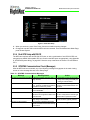
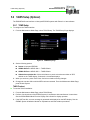
5.4 Using the Maintenance Mode Page ..............................................................................................27
5.4.1 Entering Maintenance Mode................................................................................................. 27
5.4.2 Working in Maintenance Mode ............................................................................................. 28
5.5 GPS/FMS Navigators Setup ......................................................................................................... 30
5.5.1 GAMA 429 Graphics Setup ..................................................................................................31
5.5.2 Dual GPS Setup with GAMA 429 ......................................................................................... 32
5.5.3 RS-232 Setup ....................................................................................................................... 32
5.5.4 Dual GPS Setup with RS-232...............................................................................................33
- iii -
Contents
5.5.5 GPS/FMS Communications Check (Messages)................................................................... 33
5.5.6 GPS/FMS Installation-Specific Issues .................................................................................. 34
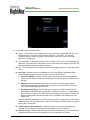
5.6 Lightning Sensor Setup................................................................................................................. 35
5.6.1 Lightning Sensor Setup ........................................................................................................ 36
5.6.2 Lightning Sensor Checkout .................................................................................................. 38
5.6.3 Lightning Sensor Noise Mode .............................................................................................39
5.7 Traffic Sensor Setup ..................................................................................................................... 40
5.7.1 Setting up the Traffic Sensor ................................................................................................ 40
5.7.2 Traffic Sensor Installation Considerations ............................................................................ 41
5.7.3 Traffic Sensor Checkout Procedures.................................................................................... 42
5.7.4 Traffic Communications Check (Messages) ......................................................................... 43
5.8 TAWS Setup (Optional)................................................................................................................. 44
5.8.1 TAWS Setup......................................................................................................................... 44
5.8.2 TAWS Communications Check (Messages) ........................................................................ 45
5.9 Radar Sensor Setup...................................................................................................................... 46
5.9.1 Supported Radar Features ................................................................................................... 46
5.9.2 Setting up Radar Support ..................................................................................................... 48
5.9.3 Radar Configuration Options ................................................................................................ 48
5.9.4 Adjusting the Roll Trim ......................................................................................................... 49
5.9.5 Calibrating the Radar System............................................................................................... 49
5.9.6 Radar Checkout.................................................................................................................... 57
5.9.7 Radar Communications Troubleshooting ............................................................................. 58
5.10 Aircraft Setup .............................................................................................................................. 59
5.10.1 Two-Way Datalink Setup .................................................................................................... 60
5.10.2 Broadcast Datalink Setup ................................................................................................... 61
5.10.3 Dimming Bus Setup............................................................................................................ 63
5.11 Map Heading Source Setup ........................................................................................................ 64
5.11.1 Setup with EXP5000 PFD as Heading Source ................................................................... 64
5.11.2 Setup with GPS/FMS as Heading Source .......................................................................... 65
5.11.3 Setup with StormScope as Heading Source ...................................................................... 65
5.11.4 Setup with Traffic (TAS) as Heading Source ...................................................................... 65
5.11.5 Setup with Synchro as Heading Source ............................................................................. 66
5.11.6 Map Orientation with Track................................................................................................. 66
5.11.7 Map Heading/Track Status ................................................................................................. 67
6 Post-Installation Check ........................................................................................................ 69
6.1 System Info Pages ........................................................................................................................ 69
6.1.1 System Info > Datalink Info Page .........................................................................................69
6.1.2 System Info > Platform Info Page.........................................................................................70
6.1.3 System Info > Port Info Page................................................................................................ 70
6.2 Electro-Magnetic Interference (EMI) Check .................................................................................. 71
6.3 TWX670 Lightning Sensor Strike Test .......................................................................................... 71
6.4 WX-500 Lightning Sensor Strike Test ........................................................................................... 72
6.5 Traffic Test .................................................................................................................................... 72
6.6 ORBCOMM Satellite Reception (EX500 Only) ............................................................................. 72
- iv -
Contents
6.7 Broadcast Datalink Satellite Reception ......................................................................................... 73
6.8 Datalink Display Test .................................................................................................................... 74
6.9 Magnetic Compass Swing............................................................................................................. 74
7 EX500 General Maintenance ................................................................................................ 75
7.1 Cleaning the EX500/EX600 Screen ..............................................................................................75
7.2 MFD Data Updates ....................................................................................................................... 75
7.2.1 Loading NavData (the Navigation Database) ....................................................................... 76
7.2.2 Loading CMax Chart Data .................................................................................................... 77
8 Avidyne Technical Support and Service ............................................................................ 79
8.1 Technical Support ......................................................................................................................... 79
8.2 Service .......................................................................................................................................... 79
9 AC 20-68B Recommended Radiation Safety ...................................................................... 81
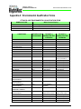
Appendix A: Environmental Qualification Forms ................................................................. 83
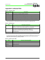
Appendix B: Authorized TSOs................................................................................................ 84
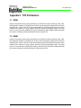
Appendix C: STC Permissions ............................................................................................... 85
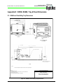
Appendix D: EX500, EX600, Tray & Panel Dimensions ........................................................ 86
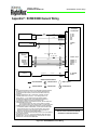
Appendix E: ORBCOMM Two-Way Datalink Antenna Installation (EX500 Only) ............... 94
Appendix F: EX500/EX600 General Wiring ............................................................................ 95
Appendix G: GPS/FMS System Wiring .................................................................................. 96
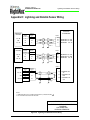
Appendix H: Lightning and Datalink Sensor Wiring............................................................. 97
Appendix I: Traffic Sensor Wiring .......................................................................................... 98
Appendix J: Radar Wiring ..................................................................................................... 100
-v-
List of Figures
Figure 1: Main Connector Sample Port Assignments................................................................................. 10
Figure 2: Sample EX500/EX600 Panel Placements................................................................................... 14
Figure 3: Heading Configuration with GPS/FMS ........................................................................................ 22
Figure 4: Heading Configuration with StormScope .................................................................................... 22
Figure 5: Heading Configuration with SkyWatch ........................................................................................ 22
Figure 6: Connecting Heading Source through Synchro Interface ............................................................. 23
Figure 7: Example Maintenance Mode Page ............................................................................................. 27
Figure 8: GPS Setup, GAMA 429............................................................................................................... 31
Figure 9: Dual GPS Setup .......................................................................................................................... 33
Figure 10: Selection Page .......................................................................................................................... 36
Figure 11: WX-500 Setup Page.................................................................................................................. 36
Figure 12: TWX670 Setup Page................................................................................................................. 37
Figure 13: Sample Traffic Setup Pages...................................................................................................... 41
Figure 14: TAWS Setup Page .................................................................................................................... 44
Figure 15: Radar Setup Page..................................................................................................................... 48
Figure 16: Radar Setup Page..................................................................................................................... 52
Figure 17: Aircraft Setup Page with Datalink..............................................................................................59
Figure 18: System Info—MLX Info Page for Iridium ................................................................................... 60
Figure 19: System Info—Datalink Info Page for ORBCOMM ..................................................................... 61
Figure 20: Map Setup Page for Track ........................................................................................................ 66
Figure 21: System Info > Datalink Info Page ..............................................................................................69
Figure 22: System Info > Platform Info Page..............................................................................................70
Figure 23: System Info > Port Info Page .................................................................................................... 70
Figure 24: TWX670 Lightning Sensor Strike Test Pattern.......................................................................... 71
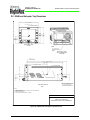
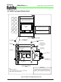
Figure 25: EX600 and Fixed-Wing Tray Dimensions ................................................................................. 86
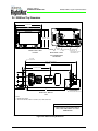
Figure 26: EX600 and Helicopter Tray Dimensions ................................................................................... 87
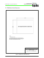
Figure 27: EX600 Panel Cut-Out Dimensions ............................................................................................ 88
Figure 28: EX600 Fixed-Wing Tray Support Structure Panel..................................................................... 89
Figure 29: EX600 Helicopter Tray Support Structure Panel.......................................................................90
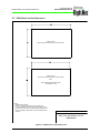
Figure 30: EX500 and Tray Dimensions..................................................................................................... 91
Figure 31: EX500 Panel Cut-Out Dimensions ............................................................................................ 92
Figure 32: EX500 Tray Support Structure Panel ........................................................................................ 93
Figure 33: Installing the 2-Way Datalink Antenna ...................................................................................... 94
Figure 34: EX500/EX600 General Wiring................................................................................................... 95
Figure 35: GPS/FMS Sub-System Wiring .................................................................................................. 96
Figure 36: Lightning and Datalink Sensor Wiring ....................................................................................... 97
Figure 37: Traffic Wiring: TAS, TCAS, TCAD, TIS ..................................................................................... 98
Figure 38: Traffic/TAWS Wiring.................................................................................................................. 99
Figure 39: Digital Radar Wiring ................................................................................................................100
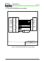
Figure 40: RDR-130/150/160 RADAR Direct Connect Wiring ..................................................................101
Figure 41: RDR-130/150/160 RADAR w/Adaptor Cable Wiring ...............................................................102
Figure 42: RDR-1100/1200 RADAR Direct Connect Wiring .....................................................................103
Figure 43: RDR-1100/1200 RADAR w/Adaptor Cable Wiring ..................................................................104
- vi -
List of Figures
Figure 44: RDR-1300 RADAR Direct Connect Wiring..............................................................................105
Figure 45: RDR-1300 RADAR w/Adaptor Cable Wiring ...........................................................................106
Figure 46: WXR250/270/300 RADAR w/ Adaptor Cable Wiring...............................................................107
- vii -
List of Tables
Table 1: EX500 Technical Specifications ..................................................................................................... 4
Table 2: EX600 Technical Specifications ..................................................................................................... 4
Table 3: Sensor Port Configuration Options................................................................................................. 5
Table 4: Main Connector (P2) Pin Assignments........................................................................................... 7
Table 5: ARINC Port Pinout Cross-Reference ............................................................................................. 8
Table 6: RS-232 Port Pinout Cross-Reference ............................................................................................ 9
Table 7: EX500 Part Numbers.................................................................................................................... 11
Table 8: EX600 Part Numbers.................................................................................................................... 11
Table 9: Heading Source Options .............................................................................................................. 18
Table 10: Suggested Two-Way Datalink Antennas .................................................................................... 19
Table 11: Hardware and Software Part Numbers....................................................................................... 28
Table 12: GPS/FMS Manufacturer’s Matrix................................................................................................ 30
Table 13: GPS/FMS Communications Messages ...................................................................................... 33
Table 14: TWX670 Configuration Options.................................................................................................. 35
Table 15: WX-500 Configuration Options................................................................................................... 35
Table 16: Lightning Sensor Messages ....................................................................................................... 38
Table 17: Traffic System Configuration Options......................................................................................... 40
Table 18: Traffic Communication Messages ..............................................................................................43
Table 19: TAWS Error Messages............................................................................................................... 45
Table 20: Radar Feature Matrix.................................................................................................................. 46
Table 21: Radar Options ............................................................................................................................ 48
Table 22: Radar Beam Widths ................................................................................................................... 49
Table 23: Radar Sensor Error Messages ................................................................................................... 58
Table 24: Broadcast Datalink Messages .................................................................................................... 63
Table 25: Map Heading Source Options .................................................................................................... 64
Table 26: Data Valid Options for Synchro .................................................................................................. 66
Table 27: Authorized TSOs ........................................................................................................................ 84
Table 28: TSO Deviations .......................................................................................................................... 84
Table 29: Partial Function TSOs ................................................................................................................ 84
- viii -
Installation Manual
P/N 600-00175-000 Rev 04
About the EX500/EX600 MFD
1 About the EX500/EX600 MFD
The Avidyne Multi-Function Display, or MFD, is a single unit computer system mounted in an aircraft
instrument panel in the pilot's view that interfaces to various aircraft avionics. The MFD increases pilot
situational awareness and enhances flight safety by providing supplementary navigation, traffic,
terrain, airspace, weather, and approach chart information.
This manual contains information about the physical, mechanical, electrical characteristics, and
installation instructions for the Avidyne FlightMax EX500 and EX600-Series Multi-Function Displays
(MFDs), Part Numbers 700-00007-001 through -006, -701 through -706, -801 through-806, and -901
through -906, along with 700-00167-001 through -006, -011 through -016, and -905 through -906
containing Software Part Number 530-00193-000, -200, 530-00201-800, -900.
Note:
For information about earlier releases of the EX500, see the EX500-Series Installation Manual
P/N 600-00079-000.
The EX500/EX600 MFDs are intended for use as a supplementary situational awareness device. The
EX500/EX600 contains software developed in accordance with RTCA/DO-178B Level D requirements.
This section contains the following information:
●
Section 1.1, “Standard Functionality” on page 1
●
Section 1.2, “Optional Functionality” on page 1
A complete FlightMax EX500/EX600-Series Multi-Function Display system consists of the following
components:
●
Avidyne FlightMax EX500/EX600-Series Multi-Function Display (MFD).
●
Fixed-Wing OR Helicopter system installation kit, including MFD assembly and necessary
connectors.
●
User documentation including Pilot's Guide, Installation Manual, and Instructions for Continued
Airworthiness.
1.1 Standard Functionality
MFD standard functionality available on the EX500/EX600:
●
A GPS interface to provide position, velocity, and flight plan data to the MFD.
●
The MFD displays the current aircraft position and active flight plan graphically overlaid on the
moving map comprised of terrain, geo-political boundaries, airspace, navaids, airports, airways,
and obstacles.
●
The MFD displays the current active flight plan in textual format.
1.2 Optional Functionality
The following features are optional for the EX500/EX600:
●
External traffic detection system—Allows the MFD to display a pictorial representation of
nearby transponder-equipped aircraft overlaid on the moving map display.
-1-
Installation Manual
P/N 600-00175-000 Rev 04
Optional Functionality
●
External lightning detection system—Allows the MFD to present a visual display of lightning
strikes or cells overlaid on the moving map display.
●
Two-Way Datalink transceiver—Allows the MFD to display strategic weather and airspace
information in graphical and textual formats. Supports either:
■
Note:
■
Note:
External MLX770 Iridium Datalink Transceiver
EX500 Release 4 or greater software is required to support the MLX770 Iridium Datalink
Transceiver. All Iridium or MLX770 references in this document assume Release 4 or greater
software is installed in the EX500.
Built-in ORBCOMM Datalink Transceiver
EX500/EX600 Release 4.1 or greater software does not support the ORBCOMM Datalink
Transceiver. All references to the ORBCOMM Datalink Transceiver only apply to EX500
Software 530-00193-020 and earlier.
●
External Broadcast Datalink receiver—Allows the MFD to display strategic weather and
airspace information in graphical and textual formats. When used with Two-Way Datalink, the
MultiLink feature can be enabled and used.
●
External Terrain Awareness and Warning System (TAWS)—Allows the MFD to display
EGPWS terrain image data on a TAWS page.
●
●
Terminal and Procedure Chart Data (CMax™ Charts)—Optional charts available from Jeppesen
Sanderson, Inc. provide terminal and procedure charts at the touch of a button.
External Digital or Analog Radar Receiver/Transmitter—Allows the MFD to display radar
image data on a radar page or overlaid on the moving map display.
-2-
Installation Manual
P/N 600-00175-000 Rev 04
General Information
2 General Information
This section contains the following information:
➥
●
Section 2.1, “Equipment Description” on page 3
●
Section 2.2, “MFD Technical Specifications” on page 4
●
Section 2.3, “Configuration Options” on page 5
To obtain maximum performance from the MFD, follow the installation instructions carefully.
MFD operating information is contained in the EX500/EX600 Multi-Function Display Pilot's Guide,
which is supplied with the MFD.
➥
Avidyne strongly recommends that you review the Pilot’s Guide before operating the MFD.
The current version of the EX500/EX600 Multi-Function Display Pilot's Guide is available on the web at
www.avidyne.com.
Note:
!
The conditions and tests required for TSO approval of this article are minimum performance
standards. It is the responsibility of those installing this article either on or within a specific type
or class of aircraft to determine that the aircraft installation conditions are within the TSO
standards. TSO articles must have separate approval for installation in aircraft. The article
may be installed only if the installation is performed in accordance with Part 43 or the
applicable airworthiness requirements.
Warning: AC 20-68B, Recommended Radiation Safety, sets forth recommended
radiation safety precautions to be taken by personnel when operating airborne weather
radar on the ground. Dangers from ground operation of airborne weather radar include
the possibility of human body damage and ignition of combustible material by radiated
energy. The full text of this FAA Advisory Circular may be found on the web at
http://faa.gov/RegulatoryAdvisory/ac_index.htm.
2.1 Equipment Description
A complete FlightMax EX500/EX600-Series Multi-Function Display system consists of the following
components:
●
EX500/EX600 Multi-Function Display (MFD), with standard and optional interfaces.
●
System installation kit including MFD tray assembly, and necessary connectors.
●
Optional radar interface cables connecting the MFD to the radar receiver/transmitter. These
cables provide a simplified connection to the pre-existing wiring.
●
Zip Drive Dataloader (250MB), connector cable, and Zip Disk, or for Release 3 and later, a USB
Flash Memory Drive. For more information about loading data for Release 3 and later, see the
Avidyne Data Update Guide (Document number 600-00148-000).
●
User documentation, including the EX500/EX600 MFD Pilot's Guide and Installation Manual
(optional).
-3-
Installation Manual
P/N 600-00175-000 Rev 04
MFD Technical Specifications
2.2 MFD Technical Specifications
Table 1: EX500 Technical Specifications
Standard Features
Display
High Brightness Sunlight Readable Color AMLCD
Diagonal size
5.5 inches
Interfaces
RS-232, ARINC 429, ARINC 453, ARINC 407 & TTL
Physical Characteristics
Weight with tray
With Quake SC:
7.2 lbs
Without Quake SC:
6.8 lbs
Height
4.35 inches (Face Plate)
Width
6.25 inches (Face Plate)
Depth
12.8 inches (Tray incl. Rear connectors)
Viewing Angle
Vertical:
+30°, -10°
Horizontal:
60° left and right of center
Operating Limits
Voltage
18-32 VDC, negative ground
Current
Maximum: 5 A at 28V
See Appendix A: Environmental Qualification Forms, on page 83 for Environmental Qualification Form
Table 2: EX600 Technical Specifications
Standard Features
Display
High Brightness Sunlight Readable Color Transflective LCD
Diagonal size
5.78 inches
Interfaces
RS-232, ARINC 429, ARINC 453, ARINC 407 & TTL
Physical Characteristics
Weight with tray
With Fixed Wing Tray:
6.2 lbs
With Helicopter Tray:
9.2 lbs
Height
4.93 inches (Face Plate Front), 4.21 inches (Rear)
Width
6.25 inches (Face Plate)
Depth
12.79 inches (Tray incl. Rear connectors)
Viewing Angle
Vertical:
+30°, -10°
Horizontal:
60° left and right of center
Operating Limits
Voltage
18-32 VDC, negative ground
Current
Maximum: 3 A at 28V
See Appendix A: Environmental Qualification Forms, on page 83 for Environmental Qualification Form
-4-
Installation Manual
P/N 600-00175-000 Rev 04
General Information
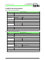
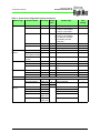
2.3 Configuration Options
To support the many sensor types encountered in the typical aircraft installation, the installer must
configure the EX500/EX600 for the sensor type and select the correct port configuration. Table 3 lists
sensor options and their associated port configurations. This data may be used when executing
Maintenance Mode sensor setup utilities. Port selection must match the aircraft wiring. Default port
assignments must match the wiring diagrams shown in Appendix F: EX500/EX600 General Wiring, on
page 95 through Appendix J.8 WXR250/270/300 RADAR w/Adaptor Cable Wiring, on page 107.
When the MFD is used in conjunction with a digital radar system, ARINC 429 TX port 3 and ARINC
453 RX port 1 are default settings, which are not selectable via the procedures contained in this
document. Table 4, “Main Connector (P2) Pin Assignments,” on page 7 provides a cross reference
between port assignments and functional use.
The selected ports are displayed on the Port Info Page, described in Section 6.1, “System Info Pages”
on page 69
Table 3: Sensor Port Configuration Options
Sensor Type
GPS/FMS
Sensor Option
GAMA 429 Format
King/Aviation Format
Port Type Default
Port
ARINC 429
RS-232
System Type
Port
Config.
1
Garmin GPS 155XL,
GNC 300XL
Speed: Low
1
Garmin GPS 400/500
Speed: Low
1
Garmin GNC 420
Speed: Low
1
Garmin GNS 430/530 (including
430W/530W)
(GAMA 429 Graphics w/INT)
Speed: Low
1
Bendix/King GNS-XLS
Speed: Low
1
Bendix/King KLN-90B
Speed: High
1
Universal UNS-1B
Speed: High
1
Bendix/King GNS-XLS
Baud: 9600
Bendix/King KLN-89B
Baud: 9600
Bendix/King KLN-90B
Baud: 9600
1
Bendix/King KLN-94
Baud: 9600
1
Garmin GNS 430/530
Baud: 9600
1
Garmin GNS 480
Baud: 9600
1
Trimble 2000, 2101
Baud: 9600
1
UPSAT – all GPS units
Baud: 9600
Northstar Format
RS-232
1
Northstar M3
Baud: 9600
NMEA 0183 Format
RS-232
1
Garmin 150/250
Baud: 4800
-5-
Installation Manual
P/N 600-00175-000 Rev 04
Configuration Options
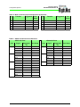
Table 3: Sensor Port Configuration Options (Continued)
Sensor Type
Traffic
Sensor Option
Not Installed
RS-232 Devices
Port Type Default
Port
—
—
RS-232
2
■
■
■
TAS
ARINC429
2
■
■
■
■
TIS-G
2
TCAS
Broadcast
Datalink
Not Installed
Port
Config.
—
—
Avidyne TAS600 Series
Avidyne TCAD 9900BX
Avidyne TCAD 9900B
—
Avidyne TAS600 Series
Avidyne TCAD 9900BX
L3 Skywatch, Skywatch
Bendix/King KTA-870,
KMH-880
—
Garmin GTX330
—
2
Goodrich TCAS 791
—
2
Bendix/King CAS-66A, KTA-970
—
—
Avidyne MLB700 (to
RS-232
Sirius satellite network)
XM WX Datalink
Receiver
System Type
RS-232
4
—
Avidyne MLB700
—
Heads Up Technologies, XMD076
—
Two-Way Datalink Not Installed
Lightning
—
Iridium
RS-232
Avidyne MLX770
—
ORBCOMM
RS-232
Avidyne ORBCOMM SC (EX500
only)
—
Not Installed
—
—
TWX670
RS-232
3
Avidyne TWX670
—
—
WX-500
RS-232
3
L3 WX500
—
Radar
The radar port is factory configured and requires no setup.
TAWS
Not Installed
Map Heading
{Source}
—
—
Honeywell EGPWS
ARINC 429
4
—
ARINC 453
2
GPS/FMS
ARINC 429
—
Traffic
ARINC 429
Multiple manufacturers
Stormscope
ARINC 429
L3 Stormscope
—
Honeywell EGPWS
—
Multiple manufacturers
—
Avidyne EXP5000 PFD RS 232/
ARINC 429
Avidyne
None (use GPS Track) RS 232/
ARINC 429
Multiple manufacturers
-6-
—
Installation Manual
P/N 600-00175-000 Rev 04
General Information
Table 4: Main Connector (P2) Pin Assignments
Pin
Function
Suggested
Your
Setup
Pin
Function
1
TTL1 (R/T ON)
40
28 VDC
2
RESERVED
41
28 VDC
Suggested
3
RESERVED
42
28 VDC
4
GND
43
ARINC 429 TX1 A
5
ARINC 429 RX1 A
44
RESERVED
6
ARINC 429 TX2 A
45
ARINC 429 RX2 A
TRAFFIC
7
TTL2 (TAS)
46
ARINC 429 TX3 A
RADAR
8
ARINC 429 RX3 A
47
TTL3 (TAS)
9
ARINC 429 TX4 A
10
RS232 TX1
11
RS232 RX1
GPS A
12
RS232 RTN1
GPS A
13
RESERVED
52
RESERVED
14
RESERVED
53
RESERVED
15
GND
54
SYNCHRO Z IN
16
SYNCHRO X IN
55
ARINC 453 TX3 A
(UNUSED)
17
SYNCHRO REF LO
56
ARINC 453 RX2 A
TAWS
18
DIMMING
57
GND
19
RESERVED
58
ARINC 453 TX3 B
(UNUSED)
20
GND
59
ARINC 453 RX2 B
TAWS
21
RESERVED
60
PWR GND
22
RESERVED
61
PWR GND
GPS A
TAWS
48
ARINC 429 RX4 A
49
RS232 TX3
Lightning sensor
50
RS232 RX3
Lightning sensor
51
RS232 RTN3
Lightning sensor
23
RESERVED
62
PWR GND
24
RESERVED
63
ARINC 429 TX1 B
25
ARINC 429 RX1 B
26
ARINC 429 TX2 B
GPS A
64
RESERVED
65
ARINC 429 RX2 B
TRAFFIC
RADAR
27
RESERVED
66
ARINC 429 TX3 B
28
ARINC 429 RX3 B
67
RESERVED
29
ARINC 429 TX4 B
TAWS
68
ARINC 429 RX4 B
30
RS232 TX2
TCAD
69
RS232 TX4
Broadcast
Datalink,
MLX770, or
GPS B
31
RS232 RX2
TCAD
70
RS232 RX4
Broadcast
Datalink,
MLX770, or
GPS B
32
RS232 RTN2
TCAD
71
RS232 RTN4
Broadcast
Datalink
MLX770, or
GPS B
33
SYNCHRO VALID
72
RESERVED
34
RESERVED
73
RESERVED
-7-
Your
Setup
Installation Manual
P/N 600-00175-000 Rev 04
Configuration Options
Table 4: Main Connector (P2) Pin Assignments (Continued)
Pin
Function
Suggested
Your
Setup
Pin
Function
Suggested
35
SYNCHRO Y IN
74
SYNCHRO REF HI
36
GND
75
ARINC 453 RX1 A
37
GND
76
RESERVED
38
RESERVED
77
RESERVED
39
RESERVED
78
ARINC 453 RX1 B
Your
Setup
RADAR
RADAR
Table 5: ARINC Port Pinout Cross-Reference
ARINC 429 Ports
Port
1
2
3
4
Signal
TX A
Suggested
Pin
ARINC 453 Ports
Your Setup
Port
43
1
Signal
TX A
Suggested
Pin
N/A
TX B
63
TX B
N/A
RX A
5
RX A
75
RX B
25
RX B
78
TX A
6
TX A
N/A
2
TX B
26
TX B
N/A
RX A
45
RX A
56
RX B
59
TX A
55
TX B
58
RX B
65
TX A
46
TX B
66
RX A
8
RX B
28
TX A
9
TX B
29
RX A
48
RX B
68
3
-8-
Your Setup
Installation Manual
P/N 600-00175-000 Rev 04
General Information
Table 6: RS-232 Port Pinout Cross-Reference
RS-232 Ports
Port
1
2
3
4
➥
Signal
Pin
TX
10
RX
11
RTN
12
TX
30
RX
31
RTN
32
TX
49
RX
50
RTN
51
TX
69
RX
70
RTN
71
Your Setup
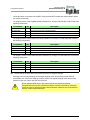
Note that the connector assignments are suggested, but not required. If you use different pin
assignments, be sure to document the changes.
-9-
Installation Manual
P/N 600-00175-000 Rev 04
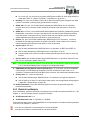
Configuration Options
TAWS 453: ARINC 453 RX #2
RADAR 453:ARINC 453 RX #1
20
59
39
DIMMING
19
SYNCHRO
18
78
58
38
77
57
37
17
76
56
36
16
75
55
35
15
74
54
34
14
TRAFFIC 232: RS-232 #2
GPS A 232: RS-232 #1
73
53
33
13
72
32
12
71
31
ARINC 429 RX #3
9
29
68
48
28
67
RADAR 429: ARINC 429 TX #3
66
TRAFFIC 429: ARINC 429 RX #2
47
27
7
46
26
6
65
45
25
5
64
44
24
4
63
AVIONICS POWER: RTN
43
23
3
62
42
22
2
61
41
21
1
TAWS 429: ARINC 429 RX #4
49
8
GPS A 429: ARINC 429 RX #1
69
50
30
10
70
RS-232 #4: MLX770,
Broadcast Datalink, or
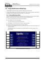
GPS B
51
11
TAWS 429: ARINC 429 TX #4
LIGHTNING 232: RS-232 #3
52
60
40
AVIONICS POWER: 28 VDC
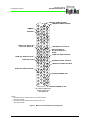
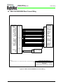
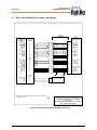
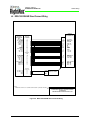
P2 - MAIN CONNECTOR
SERIAL DATA PORT
ASSIGNMENTS
NOTES:
1. AVAILABLE FOR GPS B WHEN TRAFFIC 429: ARINC 429 RX #2
PORT IS NOT WIRED
2. AVAILABLE FOR GPS B WHEN TAWS 429: ARINC 429 TX #4
PORT IS NOT WIRED
Figure 1: Main Connector Sample Port Assignments
- 10 -
Installation Manual
P/N 600-00175-000 Rev 04
Unpacking the MFD
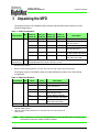
3 Unpacking the MFD
The shipping carton for the FlightMax EX500, Avidyne P/N 850-00010-XXX contains one of the
following configurations:
Table 7: EX500 Part Numbers
Part Number
700-00007-()
Qty
1
600-00078-000
600-00078-001
1
Black w/
Quake SC
Grey no
Quake SC
Black, no
Quake SC
Grey w/
Quake SC
Description
-001
-701
-801
-901
EX500, no RADAR
-002
-702
-802
-902
EX500, RDR1100/1200 (RT131A*, RT-1201A1*)
-003
-703
-803
-903
-004
-704
-804
-904
EX500, RDR 130/150 (RT-131A)
RDR 160 (ART-161A†)
-005
-705
-805
-905
EX500, RDS8X, RDR2XXX
(RS-18X, RS-8XX, ART-2XXX)
-006
-706
-806
-906
EX500, WXR270/270A
(WXT-250A, WXT-250B)
EX500, RDR1300 (RT-1301A1∗)
FlightMax EX500-Series MFD Pilot's Guide.- Pre-Release 4, or
EX500/EX600 MFD Pilot's Guide.- Release 4 or Later
*.
With DA-1203A antenna
†.
With one of the following antennas: AT-133A, DA-144A, AT-133A inverted, DA-144A inverted
The shipping carton for the EX600, Avidyne P/N 850-00208-XXX contains one of the following
configurations:
Table 8: EX600 Part Numbers
Part Number
700-00167-()
Qty
1
600-00078-001
1
Black
Grey
Description
-001
-011
EX600, no RADAR
-002
-012
EX600, RDR1100/1200 (RT131A*, RT-1201A1*)
-003
-013
-004
-014
EX600, RDR 130/150 (RT-131A)
RDR 160 (ART-161A†)
-005
-015
EX600, RDS8X, RDR2XXX
(RS-18X, RS-8XX, ART-2XXX)
-006
-016
EX600, WXR270/270A
(WXT-250A, WXT-250B)
EX600, RDR1300 (RT-1301A1∗)
EX500/EX600 MFD Pilot's Guide.- Release 4 or Later
*.
With DA-1203A antenna
†.
With one of the following antennas: AT-133A, DA-144A, AT-133A inverted, DA144A inverted
Note:
When unpacking or servicing the EX500/EX600, do not lay the MFD down on its face. This
can break the knobs and render the MFD unusable.
- 11 -
Installation Manual
P/N 600-00175-000 Rev 04
Configuration Options
Locate the labels on the bottom of the MFD. Verify that the MFD includes the ordered feature option
set marked on the label.
The shipping carton of the FlightMax EX500 Installation Kit, Avidyne P/N 850-00011-000 contains the
following components:
Part Number
Qty
Description
700-00009-000
1
EX500 Tray Assembly
030-00181-000
1
Connector, D-Sub 78F, w/ backshell & Pins
150-00100-000
8
Screw, 4-40 x ¼ Flat, SS, 100 Degree
600-00004-000
1
EX500 Installation Documentation CD
The shipping carton of the EX600 Fixed-Wing Installation Kit, Avidyne P/N 800-00039-000 contains
the following components:
Part Number
700-00168-000
Qty
1
Description
EX600 Fixed Wing Tray Assembly
030-00181-000
1
Connector, D-Sub 78F, w/ backshell & Pins
150-00100-000
8
Screw, 4-40 x ¼ Flat, SS, 100 Degree
600-00011-000
1
EX600 Installation Documentation CD
The shipping carton of the EX600 Helicopter Installation Kit, Avidyne P/N 800-00039-001 contains the
following components:
Part Number
Qty
Description
700-00168-001
1
EX600 Helicopter Tray Assembly
030-00181-000
1
Connector, D-Sub 78F, w/ backshell & Pins
150-00100-000
8
Screw, 4-40 x ¼ Flat, SS, 100 Degree
600-00011-000
1
EX600 Installation Documentation CD
➥
Ensure that all the parts were received and sustained no shipping damage.
If damage occurs during shipping, the damaged shipping carton and packing material will help
substantiate your claim to the shipping company. Retain the original shipping carton and packing
material in case you need to ship the unit for service.
!
Do not open the MFD cover in any manner and do not remove the internal
CompactFlash memory card, unless the operation is being conducted by authorized
personnel using an approved Avidyne Service Bulletin. Otherwise, the CompactFlash
memory or MFD may be damaged.
- 12 -
Installation Manual
P/N 600-00175-000 Rev 04
Installation Planning
4 Installation Planning
This section contains information for installing and wiring the MFD. All installation procedures should
follow the acceptable practices, methods, and techniques of avionics installations as described in FAA
Advisory Circulars. Use appropriate appendices for guidance with MFD dimensions and panel cutout
requirements.
Installations not identified in applicable STCs may require additional substantiation. See Appendix C:
STC Permissions, on page 85 for information pertaining to STCs. Referring to an STC may assist in
securing installation approval.
4.1 Location and Viewing Angle
The EX500/EX600 is designed for panel mounting using the mounting tray supplied with the unit
installation kit. Locate the MFD in a position on the panel where the pilot can easily reach the knobs
and controls to operate and view it from the proper viewing angle.
Viewing Angle Limits
Vertical
Up 30º, Down 10º [+30º/-10º]
Horizontal
Left and Right 60º [± 60º]
4.2 TSO-C157 Requirements
The FIS-B (Flight Information Services-Broadcast) equipment installer needs to assess FIS-B
equipment integration with other avionics and airborne applications, such as integration of FIS-B
display products with display of terrain, proximate aircraft traffic information, flight plan overlays,
moving map displays, etc.
Manufacturers, installers, and applicants must assess identification of display integration issues, and
their potential impact upon FIS-B equipment design and developmental assurance, during equipment
installation. For example, FIS-B equipment may share common avionics display resources hosting
multiple applications. Evaluate here, the installation for hazards contributed by FIS-B equipment
malfunction that may cause loss or malfunction of other aircraft applications.
Limited display resource computing capability will require the installer to review display resource
priority schemes to ensure FIS-B equipment does not preclude, corrupt, or delay display of
applications necessary for the continued safe flight of the aircraft. Installers must assess the
incompatible use of common color coding philosophies and symbology.
4.3 Class III Aircraft Installations
➥ When installed in a Class III aircraft, the EX500 and EX600 STCs require an independent lightning
detection and display system complying with TSO-C110a to be installed and operational for flights in
IMC. Additionally, an FAA-approved Flight Manual Supplement is required and must be carried
aboard the aircraft during all flights.
- 13 -
Installation Manual
P/N 600-00175-000 Rev 04
Cooling Requirements
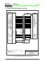
AUDIO PANEL
TRANSPONDER
EX600 or
EX500
ADF OR OTHER AVIONICS
GPS/NAV/COM
GPS/NAV/COM
AUTOPILOT OR OTHER
AVIONICS
MFD PLACEMENT IN PANEL OF
SMALLER AIRCRAFT (TYPICAL)
AUDIO PANEL
EX600 or
EX500
TRANSPONDER
ADF OR OTHER
AVIONICS
GPS/NAV/COM
GPS/NAV/COM
AUTOPILOT
MFD PLACEMENT IN PANEL OF
LARGER AIRCRAFT (TYPICAL)
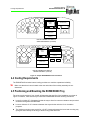
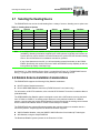
Figure 2: Sample EX500/EX600 Panel Placements
4.4 Cooling Requirements
The EX500/EX600 includes internal cooling provisions to maximize operational reliability.
➥
Make sure that the air vents located at the rear and sides of the unit/tray assembly are not
obstructed.
4.5 Positioning and Mounting the EX500/EX600 Tray
The unique requirements of your aircraft will determine the specifics of the installation, as shown in
Figure 2. However, make sure that you install the EX500/EX600 with the following clearances:
●
Leave four inches (4”) of clearance behind the tray to allow for connector clearance and permit air
circulation through the EX500/EX600.
●
Leave a minimum of 1/8” clearance between the tray and other avionics for air circulation
purposes.
●
The Avidyne mounting trays provide for a 0.125" clearance between the bezel and mounting tray
(along the sides and top of the tray) to allow for any panel thickness.
- 14 -
Installation Manual
P/N 600-00175-000 Rev 04
Installation Planning
When you install the EX500/EX600 tray, ensure that the mounting tray is installed at the proper depth
in the panel to allow the connectors of the EX500/EX600 to fully seat in the connectors of the mounting
tray. When properly installed, the EX500/EX600 bezel will contact the protruding lip on the bottom of
the tray.
Make sure that the structural aspects of the installation are performed in accordance with AC43.13-2A,
Chapter 1. See D.8 EX500 Tray Support Structure Panel, on page 93 for details on tray mounting and
support.
!
Caution: It is extremely important that the 0.125” panel thickness is not exceeded, or
the EX500/EX600 may not fully seat in the mounting tray. If communication between the
EX500/EX600 and any of the sensor interfaces is not established, ensure that the
EX500/EX600 is fully seated in the tray, and then check all sensor connections.
!
When other avionics are installed with the EX500/EX600, ensure that the installation
does not result in a deflection of the aircraft magnetic compass of greater than 10
degrees.
Note:
Once the tray is mounted in place, you can install or remove the connectors and the back
plate. To remove the back plate, unscrew the six screws that hold it in place.
4.6 Electrical and Sensor Interfaces
28-volt DC electrical power must be supplied to the MFD. In aircraft with a 28-volt system, the MFD is
usually connected to a non-essential avionics bus. Non-28-volt systems can use a regulated +28 VDC
converter. The MFD may be wired to the aircraft dimming bus to control front panel LED brightness via
the cockpit panel brightness control.
See Figure 34, “EX500/EX600 General Wiring,” on page 95 through Figure 46, “WXR250/270/300
RADAR w/ Adaptor Cable Wiring,” on page 107 for system and sensor wiring diagrams. Perform all
wiring in accordance with the FAA Advisory Circular AC 43.13-1B.
The following connectors, or their equivalents, support the EX500/EX600 tray installation.
Designation
P1
Vendor
Part Number
Description
Positronic
DD44M10G00
44-Pin High Density Male D-Sub Connector
P2
Positronic
DD78F10G00
78-Pin High Density Female D-Sub Connector
J2
Delta Electronics
4205-018-N995
50 Ohm Blind Plug BNC Connector (EX500
ORBCOMM only)
4.6.1 Electrical and Sensor Interface Wiring Notes
The following notes apply to the aircraft wiring used to install the EX500/EX600:
1. Power—P2- input: 5 A (EX500), 3 A (EX600) @ 28 vdc.
■
Use 20 AWG for lengths greater than 3ft.
■
Use 22 AWG for P2 high-density sockets.
■
7.5 amp circuit breaker is recommended for the EX500.
■
5 amp circuit breaker is recommended for the EX600.
- 15 -
Installation Manual
P/N 600-00175-000 Rev 04
Electrical and Sensor Interfaces
■
For 14 vdc A/C, use 14 to 28 vdc converter (KGS Electronics RB-125, Ameri-King AK550-6 or
similar with TSO-C71, output 5 A (EX500), 3 A (EX600) min. @ 28 vdc.)
2. Dimming—P2- input: use 22 AWG, connect to a/c instrument dimming bus. Supports any range
0-28 vdc. Connection to dimming-bus ground reference required.
3. ARINC 429—P2- wire: use 22 AWG twisted shielded pair, MS22759/18-22-2 or equivalent.
Connect shield to P2 connector metallic backshell grounding screw with solder or crimp ring
terminal.
4. ARINC 453—P2- wire: use 22 AWG twisted double shielded pair (Quadrax), (Bendix/King p/n 02400064-0000) or equivalent. Connect outer shield to P2 connector metallic backshell grounding
screw with solder or crimp terminal ring. Connect inner and outer shield to sensor connector
metallic backshell grounding screw with solder or crimp terminal ring.
5. RS-232—P2- wire: use 22 AWG shielded triple, MS22759/18-22-3 or equivalent. Connect a
dedicated RS-232 signal ground from the sensor to the MFD. Connect shield to P2 connector
metallic backshell grounding screw with solder or crimp ring terminal.
6. Synchro input—P2- wire:
■
Use 22 AWG shielded double, MS22759/18-22-2 or equivalent, for REF HI and REF LO.
■
Use 22 AWG shielded triple, MS27500/18-22-3 or equivalent, for X/Y/Z.
■
Connect shield to P2 connector metallic backshell grounding screw with solder or crimp ring
terminal.
7. Synchro Valid—Use 22 AWG shielded single, MS22759/18-22-1 or equivalent. Valid low is less
than 1.4 vdc. Valid high is greater than 2.7vdc.
Note:
The Synchro Valid input is optional. If you do not use it, no connection is required. See Section
5.10.2, “Broadcast Datalink Setup” on page 61 for configuration details.
8. ORBCOMM Two-Way Datalink antenna (EX500 Only)—J2- coax cable: use M17/128-RG400,
(Thermax/CDT p/n RGS-400) high temperature, 50 ohm, stranded core with 0.038 o.d., or
equivalent. Terminate antenna end with BNC series connector. See mechanical installation notes.
9. Analog radar—P1- control and data lines:
■
Use 22 AWG shielded single, MS22759/18-22-1 or equivalent, for trigger and data lines.
■
Use 22 AWG for all others. For the specific radar system, see the appropriate wiring diagram
in Appendix J: Radar Wiring, on page 100.
10. Shield terminations—Place the shield terminations as close to the protected signal wire
terminations as feasible.
4.6.2 Electrical Load Analysis
Prior to installation, perform an electrical load analysis on the aircraft in accordance with AC 43.13-1B,
Chapter 11. Use the following values to support the analysis:
●
28 VDC Nominal Load—2 A
●
28 VDC Maximum Load—5 A (EX500), 3 A (EX600)
Ensure that the power input to the EX500/EX600 is circuit-protected in accordance with the guidelines
of AC 43.13-1B, Chapter 11, Section 2.
➥
➥
A 7.5 amp circuit breaker is recommended for use with the EX500.
A 5 amp circuit breaker is recommended for use with the EX600.
- 16 -
Installation Manual
P/N 600-00175-000 Rev 04
Installation Planning
4.6.3 Weight and Balance Calculation
A Weight and Balance calculation aircraft is required as part of installation approval process. Follow
the guidelines as established in AC 43.13-1B, Chapter 10, Section 2. Use the unit and installation kit
materials weight as follows:
●
EX500 With Quake SC: 7.2 lb. (3.3 kg)—EX500 MFD with tray and connectors
●
EX500 Without Quake SC: 6.8 lb. (3.1 kg)—EX500 MFD with tray and connectors
●
EX600 With Fixed-Wing Tray: 6.2 lb. (2.81 kg)—EX600 MFD with fixed-wing tray and
connectors
●
EX600 With Helicopter Tray: 9.2 lb. (4.17 kg)—EX600 MFD with helicopter tray and connectors
- 17 -
Installation Manual
P/N 600-00175-000 Rev 04
Selecting the Heading Source
4.7 Selecting the Heading Source
The EX500/EX600 can receive aircraft heading from a variety of sources. Heading source options are:
Table 9: Heading Source Options
Source
System
Synchro
Interface
ARINC 407 Synchro
Source
GPS/FMS
System
Interface
GNC300XL
ARINC 429
Lightning
WX-500
RS-232
GPS 400/500
ARINC 429
Traffic
Skywatch
ARINC 429
GNS 430/530
ARINC 429
Note:
Skywatch HP
ARINC 429
KLN-90B
ARINC 429
KTA-870
ARINC 429
UNS-1B
ARINC 429
GNS-XLS
ARINC 429
KMH-880
ARINC 429
TCAS I
ARINC 429
PFD
Avidyne EXP5000 ARINC 429 or RS-232
If an Avidyne PFD is not installed, the Synchro option yields the best system reliability
(availability). Heading information supplied by the other systems is typically sourced from the
synchro and may require interface converters between the synchro and the alternate heading
source. See the manufacturer’s installation manuals for guidance.
If any of the alternate sources fail, you will lose heading related functionality on the EX500/
EX600. Specifically, this results in the loss of traffic and RADAR overlay capability as well as
forcing North Up display of the Map Page.
See Section 5.11, “Map Heading Source Setup” on page 64 and Figure 34, “EX500/EX600 General
Wiring,” on page 95 for more information about selecting the active heading source.
4.8 Datalink Antenna Installation Considerations
The EX500/EX600 supports the following 2-Way Datalink installations:
●
MLX770 Iridium Datalink transceiver
●
Built-in ORBCOMM Datalink transceiver (EX500 Release 4.0 and earlier only)
For information on MLX770 installation, refer to the MLX770 Datalink Transceiver Installation Manual
(600-00204-000).
The ORBCOMM 2-Way Datalink system is designed to work with a VHF antenna covering the band
from 137 MHz to 151Mhz. If an existing comm antenna is in the preferred location for a datalink
antenna, consider using the Avidyne DC50 Datalink Coupler and replacing the existing comm antenna
with a combined VHF/datalink antenna. Please contact Avidyne for details.
The EX500/EX600 also supports Broadcast weather data, which provides more weather data in a
more timely fashion. Avidyne supports two Broadcast Weather suppliers:
●
XM WX Satellite Weather, using the XMD076 XM WX Receiver from Heads Up Technologies.
●
WSI Weather, using the Avidyne MLB700.
The Broadcast Datalink system operates in the S-band at 2.3 GHz.
- 18 -
Installation Manual
P/N 600-00175-000 Rev 04
Installation Planning
The EX500/EX600 can operate with both Datalink systems simultaneously. With both 2-Way Datalink
and Broadcast Datalink systems installed, the MFD can provide Avidyne's unique MultiLink features,
which include text messaging, flight tracking, and enhanced weather coverage.
4.8.1 ORBCOMM Antenna Details (EX500 Release 4.0 and earlier only)
To improve ORBCOMM reception performance and minimize potential damage to the ORBCOMM
transceiver, an antenna design with a DC-short between the antenna center conductor and shield
termination is required. The following commercially available antennas are acceptable:
Table 10: Suggested Two-Way Datalink Antennas
Manufacturer
Comant
Sensor Systems
➥
P/N
Application
CI 177-4
Max 210 kts indicated at 10,000 ft.
CI 248-30
Max 210 kts indicated at 10,000 ft.
CI 108-1
Max 600 kts TAS at 35,000 ft.
CI 211-1
Max 600 kts TAS at 35,000 ft.
S65-8280-10
Max 600 kts TAS
Refer to manufacturers for detailed performance specifications and aircraft applicability
●
Mount the ORBCOMM antenna on the aircraft top-side, as high on the fuselage as practical.
●
Mount the antenna no closer than 36 inches to other transmitters. You may need to relocate other,
less location-sensitive transmitters, to achieve optimal datalink performance.
●
On radar-equipped aircraft, mount the antenna as far aft as possible, but no closer than 36 inches
from vertical obstructions (such as the vertical stabilizer). Reflected radar energy may cause
damage to the datalink transceiver.
Install the radar in accordance with the applicable portions of AC 43.13 and the antenna
manufacturer’s instructions. For more information, see Figure 33, “Installing the 2-Way Datalink
Antenna,” on page 94.
!
This Installation Manual does not contain approved data for type-specific aircraft
antenna installations.
4.8.2 Broadcast Antenna Details
●
Mount the antenna no closer than 36 inches to VHF-Comm transmitters of 15 Watts or less. For
more powerful transmitting antennas, ensure a minimum separation of 48 inches.
●
If you are installing an XM/VHF-Comm combo antenna to replace an existing approved antenna
installation, the existing separations are acceptable. SATCOM antennas transmit at 40 Watts and
should be separated by the largest distance possible. This distance must be a minimum of 36
inches.
●
When routing the broadcast antenna cable, try to achieve the maximum possible separation from
transmitter antenna feed cables, especially with SATCOM and other high power transmitters. VHF
transmitter antenna feed cables of 15 Watts or less require only a minimal separation.
●
Receive-only antennas such as GPS and ADF do not produce interference and require little
separation. To allow for separation from transmitters, you can place the XM antenna as close as
possible to these types of antennas.
●
For further details, including installation pre-testing, see the Broadcast Receiver’s installation
manual.
- 19 -
Installation Manual
P/N 600-00175-000 Rev 04
Wiring External Devices
4.9 Wiring External Devices
4.9.1 GPS and FMS Wiring
GPS data may be received via a GAMA 429 Graphics interface with intersections or an RS-232
interface. See the appropriate wiring diagram and the specific installation instructions for your
particular GPS. For more information, see Section 5.7, “Traffic Sensor Setup” on page 40.
Note:
For the EX500/EX600, Avidyne recommends using a GAMA 429 Graphics connection with
intersections for FMS/ GPS. The GAMA 429 Graphics input can contain heading data,
necessary for overlay capabilities as well as approach procedures and the display of curved
segments. For more information, see Section 5.5.1, “GAMA 429 Graphics Setup” on page 31.
4.9.2 Dual GPS Setup with GAMA 429
The EX500/EX600 can receive information from two GAMA 429 Graphics capable GPS units. Connect
the GPS according to the wiring diagram in Appendix G: GPS/FMS System Wiring, on page 96.
Select a different ARINC port for GPS 2.
4.9.3 Broadcast Datalink Receiver Wiring
See the wiring diagram in Appendix H: Lightning and Datalink Sensor Wiring, on page 97 and the
HeadsUp XMD076 Installation Manual. Connect the RS-232 port of the Datalink receiver to any of the
available RS-232 ports of the MFD as shown. (RS232 #4 is the default assignment, but not
mandatory.) Use shielded wiring, terminated at each end to chassis ground. Contact Heads Up
Technologies at www.heads-up.com for information on the HeadsUp XMD076 Broadcast Datalink
Receiver. Contact Avidyne for information on the MLB700 Multilink Broadcast Receiver.
4.9.4 Lightning Sensor Wiring
See the wiring diagram in Appendix H: Lightning and Datalink Sensor Wiring, on page 97 and the WX500 Installation Manual or the TWX670 Installation Manual. Connect the RS-232 port of the lightning
sensor to any of the available RS-232 ports of the MFD as shown. Use shielded wiring, terminated at
each end to chassis ground. Connect the lightning sensor jumpers for correct stabilization source and
antenna position. These settings will also be set in the MFD and must agree.
!
Caution: It is extremely important that you perform noise mapping and ensure that the
proper grounds have been installed and checked after the Lightning interface is
installed. Ensure that the lightning sensor is installed and set up according to its
installation instructions. Excessive noise can produce erroneous lightning strike
indications.
- 20 -
Installation Manual
P/N 600-00175-000 Rev 04
Installation Planning
4.9.5 Traffic Sensor Wiring
The MFD supports a number of different traffic sensors. Be sure to follow the instructions for the
specific traffic sensor installed on the aircraft.
●
TAS (L-3 SkyWatch: SKY497, TRC497 and TRC899)—Connect data and TTL control lines and
configure as shown in Appendix I: Traffic Sensor Wiring, on page 98. Use shielded wiring and
terminate as shown.
Note:
●
TAS/IHAS/Avidyne Traffic (Avidyne TAS600 Series, 9900B, 9900BX, Bendix/King: KTA
870)—For Avidyne products, connect aircraft power to the Avidyne TCAD sensor as described in
the Avidyne TAS600 Series Installation Manual. For other products, see the appropriate
installation documentation. Connect data lines and configure as shown in Appendix I: Traffic
Sensor Wiring, on page 98. Use shielded wiring and terminate as shown.
Note:
●
If using a TRC 497, ensure the software revision is 1.6 or later.
Ensure the 9900BX software revision is 1.07 or later.
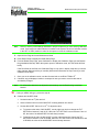
TIS-G (Garmin: GTX-330, GTX-330D)—Ensure the Garmin software revision is 3.03 or higher.
Connect data lines and configure as shown in Appendix I: Traffic Sensor Wiring, on page 98. Use
shielded wiring and terminate as shown.
Wire power to the Garmin GTX -330 transponder as directed in the Garmin Installation Manual.
Note:
The MFD does not provide power to the GTX sensor. TIS uses an ARINC 429 data connection
between the transponder and the MFD. Make this connection after consulting the wiring
diagrams in the appendix of this document and the GTX-330 installation manual.
4.9.6 TAWS Wiring
(Honeywell: KGP 560) – Ensure the KGP 560 has part number 965-1198-005. Connect as shown in I.2
Traffic/TAWS Sensors Wiring, on page 99.
The EGPWS software must support KC Picture Bus (KCPB) Phase 2. See the Honeywell EGPWS
documentation for applicable software configurations. If the EGPWS interface is operating properly,
there will be no system status messages.
4.9.7 Map Configuration
Wiring for Map can be done in a number of different ways, depending on the aircraft configuration and
options.
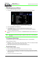
Configuring Map Heading from the EXP5000 PFD
The EX500/EX600 can receive heading directly from an installed Avidyne EXP5000 PFD via an
ARINC 429 or an RS-232 bus.
For the correct interconnection between the EXP5000 PFD and the EX500/EX600, see Table 35,
“GPS/FMS Sub-System Wiring,” on page 96.
- 21 -
Installation Manual
P/N 600-00175-000 Rev 04
Wiring External Devices
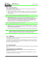
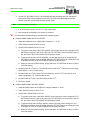
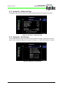
Configuring Map Heading from a GPS/FMS
The MFD can receive heading from an GPS/FMS via an ARINC 429 bus. The source of heading is
usually a gyro transmitting synchro or stepper to SkyWatch or StormScope sensor connected to the
GPS/FMS, as shown in Figure 3.
See Appendix G: GPS/FMS System Wiring, on page 96 for the correct pinouts to the MFD.
When checking the GPS/FMS connection to the EX500/EX600, the GPS/FMS must have a valid
position fix (latitude/longitude).
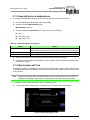
Figure 3: Heading Configuration with GPS/FMS
Configuring Map Heading from StormScope
The MFD is capable of receiving heading data from the WX-500 StormScope via RS-232. Configure
the MFD as shown in Figure 4:
Figure 4: Heading Configuration with StormScope
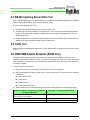
Configuring Map Heading from TAS (Traffic)
The EX500/EX600 is capable of receiving heading data from a TAS system. Configure the MFD as
shown in Figure 5. See Appendix I: Traffic Sensor Wiring, on page 98 for the correct pinouts to the
MFD.
Figure 5: Heading Configuration with SkyWatch
- 22 -
Installation Manual
P/N 600-00175-000 Rev 04
Installation Planning
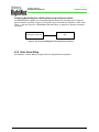
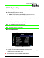
Configuring Map Heading from a Heading Source using the Synchro Interface
The EX500/EX600 is capable of receiving heading data directly from a heading source using the
Synchro interface as shown in Figure 6. The Synchro pins on the MFD are identified in Table 4 and
Figure 1. Also see Figure 34, “EX500/EX600 General Wiring,” on page 95 for Synchro connection
information.
Heading Source (Synchro)
MFD
Figure 6: Connecting Heading Source through Synchro Interface
4.9.8 Radar Sensor Wiring
See Appendix J: Radar Wiring, on page 100 for the appropriate wiring diagram.
- 23 -
Installation Manual
P/N 600-00175-000 Rev 04
Wiring External Devices
This page intentionally left blank.
- 24 -
Installation Manual
P/N 600-00175-000 Rev 04
MFD Feature Setup and Checkout
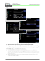
5 MFD Feature Setup and Checkout
This section contains the following information:
●
Section 5.1, “Preliminary Test” on page 25.
●
Section 5.2, “Optional MFD Function Activation Utility” on page 26
●
Section 5.3, “Using the Configuration Save and Restore (CSR) Utility” on page 26
●
Section 5.4, “Using the Maintenance Mode Page” on page 27
●
Section 5.5, “GPS/FMS Navigators Setup” on page 30
●
Section 5.6, “Lightning Sensor Setup” on page 35
●
Section 5.7, “Traffic Sensor Setup” on page 40
●
Section 5.8, “TAWS Setup (Optional)” on page 44
●
Section 5.9, “Radar Sensor Setup” on page 46
●
Section 5.10, “Aircraft Setup” on page 59
●
Section 5.11, “Map Heading Source Setup” on page 64
5.1 Preliminary Test
➤ Power up the MFD for post installation evaluation and configuration. To do so:
1. Turn on the MFD by applying power to the aircraft electrical bus supplying the MFD.
Note:
Read the EX500/EX600 Multi-Function Display Pilot’s Guide for explanations of various
functions.
2. The green LED control lights behind all the front panel controls should light up.
3. After the initial power up, the software will load and go through several checks. During this startup
sequence the screen displays the text “Initializing-Please Wait...”.
4. The startup sequence is finished when the “Press any bezel key to Continue...” message displays.
- 25 -
Installation Manual
P/N 600-00175-000 Rev 04
Optional MFD Function Activation Utility
5.2 Optional MFD Function Activation Utility
Avidyne provides the ability to install CMax using an activation utility on CompactFlash. This section
describes the installation procedure for this utility. With Release 4.1 and later MFDs, CMax is included
and activated at the factory so this procedure is not necessary.
➥
The CMax Activation Utility is available for use only by avionics repair facilities performing MFD
installations, MFD software upgrades, and MFD function activation on installed MFD software.
➤ To activate CMax, obtain the MFD CMax Activation Utility which activates the MFD CMax™ function.
This utility is for use in FAA-approved aircraft repair stations only.
The CompactFlash version of the CMax Utility will run each time that you use it. However, if run on an
MFD on which CMax is already activated, it will de-activate CMax. In that instance, running the utility
yet again will re-activate CMax. If you activate the CMax utility on an MFD, the CMax Activation Utility
will not let you activate CMax on any other MFD. Only one license is permitted per CompactFlash.
Follow the instructions in the accompanying service bulletin the CMax Activation Utility.
5.3 Using the Configuration Save and Restore (CSR) Utility
➥ The Configuration Save and Restore Utility is not used when doing field-loadable software
upgrades. It also cannot be used for transitioning from an EX500 MFD to an EX600 MFD.
When performing an upgrade to an existing MFD, you may want to use the Configuration Save and
Restore (CSR) Utility. This utility allows you to save off many of the configuration options that had
previously been set on the MFD, including:
●
Any added-cost utilities such as CMax (as described in Section 5.2, “Optional MFD Function
Activation Utility” on page 26).
●
Lightning, Traffic, GPS, and MAP parameters.
The CSR Utility can save you many hours of work and a CSR Utility CompactFlash should be included
as part of the ship kit for MFD Upgrades.
For detailed information about the CSR Utility, see the Avidyne Service Bulletin EX500 Save &
Restore Utility, Document Number 601-00007-035.
- 26 -
Installation Manual
P/N 600-00175-000 Rev 04
MFD Feature Setup and Checkout
5.4 Using the Maintenance Mode Page
The MFD Maintenance Mode Page contains the setup pages for each function.
➤ To start using the Maintenance Mode Page, apply power to all the sensors that interface with the MFD,
including the GPS, the Lightning and Traffic sensors, and TAWS sensor.
5.4.1 Entering Maintenance Mode
To enter the Maintenance Mode Page, apply power to all the sensors that interface with the EX500/
EX600, including the GPS, the Lightning and Traffic sensors, and TAWS sensor.
1. Set the aircraft avionics master ON and circuit breaker IN
2. Press PWR to turn on the EX500/EX600
The system will begin its normal start up sequence
3. At the prompt, “Press any bezel key to continue”, press any button.
4. Rotate the Page knob clockwise until the Aux Page displays.
5. Simultaneously press and hold buttons L1 (top left) and L3 (3rd down on the left) (see Figure 7) for
at least 5 seconds.
The Maintenance Mode Page displays. Note that the available setup options depend on the
specific aircraft.
L1
R1
L2
R2
L3
R3
L4
R4
L5
R5
Figure 7: Example Maintenance Mode Page
- 27 -
Installation Manual
P/N 600-00175-000 Rev 04
Using the Maintenance Mode Page
6. Record the software part number, and verify that it is compatible with the hardware part number, in
accordance with the table below.
Table 11: Hardware and Software Part Numbers
Hardware Part
Number
Software Part Number
Nomenclature
700-00007-X01
530-00193-000
530-00193-020
530-00201-800
EX500
700-00007-X02
530-00193-000
530-00193-020
530-00201-800
EX500, RDR1100/1200
700-00007-X03
530-00193-000
530-00193-020
530-00201-800
EX500, RDR1300
700-00007-X04
530-00193-000
530-00193-020
530-00201-800
EX500, RDR130/150/160
700-00007-X05
530-00193-000
530-00193-020
530-00201-800
EX500, RDS8X, RDR2XXX
700-00007-X06
530-00193-000
530-00193-020
530-00201-800
EX500, WXR250/275/300
700-00007-999
530-00134-000
530-00134-001
530-00201-899
EX500, RDS8X, RDR2XXX,
DEALER DEMO
700-00167-0X1
530-00201-900
EX600
700-00167-0X2
530-00201-900
EX600, RDR1100/1200
700-00167-0X3
530-00201-900
EX600, RDR1300
700-00167-0X4
530-00201-900
EX600, RDR130/150/160
700-00167-0X5
530-00201-900
EX600, RDS8X, RDR2XXX
700-00167-0X6
530-00201-900
EX600, WXR250/275/300
700-00167-905
530-00201-999
EX600, RDS8X, RDR2XXX,
DEALER DEMO
700-00167-906
530-00201-999
EX600, WXR250/275/300,
DEALER DEMO
5.4.2 Working in Maintenance Mode
As shown in Figure 7, the Maintenance Mode Page contains setup buttons for the available EX500/
EX600 features. When you select a Setup feature, the appropriate page displays. From the Setup
page, the following options will always be available:
●
Select Knob—Rotate to change the highlighted parameter box.
●
Change Knob—Rotate to select a parameter to modify from the highlighted box.
●
Save—Store any setup changes made since entering the page and return to the Maintenance
Mode Main page.
●
Cancel—Return to the Maintenance Mode Main page without saving your changes
- 28 -
Installation Manual
P/N 600-00175-000 Rev 04
MFD Feature Setup and Checkout
➤ When working in Maintenance Mode:
1. After making changes to each setup page press Save to save your changes and return to the main
menu.
To exit without saving your changes, press Cancel.
➥
2. Changes in the setup pages do not take effect until the MFD has been restarted. From the
Maintenance Mode Page, press Restart System.
Avidyne suggests that you restart the system after you make changes to each setup page.
If no changes were made, press Back to Map to exit Maintenance Mode.
- 29 -
Installation Manual
P/N 600-00175-000 Rev 04
GPS/FMS Navigators Setup
5.5 GPS/FMS Navigators Setup
The MFD can interface with several types of GPS/FMS systems. Table 12 lists the GPS/FMS systems
that can be used with the MFD, along with information about data formats and GPS configurations.
Table 12: GPS/FMS Manufacturer’s Matrix
GPS/FMS
RS-232 ARINC 429 Baud/ Data Heading
Rate
Output
Configuration
Notes
DME ARC
KLN-89B//94
Yes
No
RS232 – 9600 No
—
Flight Plan ends at
entry point
KLN-90B
Yes
Yes
RS232 – 9600 ARINC
ARINC – Low only
—
Flight Plan ends at
entry point
NorthStar
M1, M2, or M3*
Yes
No
1200 or 9600
No
The Northstar default baud
rate is 1200. For better
performance and extended
data, set the baud rate to
9600. See the NorthStar
manual to change the baud
rate.
Trimble 2000,
2101
Yes
Some
models
9600
No
Use RS-232 port 2
No Parity, 8 bits.
Garmin
150, 250
Yes
150- No
250-No
RS232 – 9600 ARINC
ARINC – Low only
■
■
Garmin
155, 165
Yes
Garmin 400/500 Yes
Series (including
430W/530W)
No
9600
No
Yes
RS232 – 9600 ARINC
ARINC – Low only
■
■
■
—
—
—
For RS-232, set the
Garmin to Aviation
Output.
With ARINC 429, use
GAMA Graphics with
Intersections
With ARINC 429
only. With RS-232
the arc is depicted as
a straight line
Do not use Arinc 429
—
—
—
Yes
No
RS232 -9600
Universal UNS1B
No
Yes
ARINC – High Yes
Bendix/King
GNS-XLS
No
Yes
ARINC – High Yes
or Low
Configure as follows:
■ GAMA ARINC 329 Bus
Data Set= 1.
■ Basic EFIS DME Arc
Style=1
■ Arc as Gap
Morrow Apollo
GX-50
Yes
No
9600
Use the Moving Map
format.
No
Sends multiple
waypoints around
arc
For the 250 use the
EFIS mode (not W/O
GAMA mode).
If using the NMEA
format use the 2nd
channel.
Garmin 480
*.
No
—
The arc is depicted
as a gap
—
NorthStar GPS/FMS systems use NorthStar RS-232 format. All other RS-232-capable GPS/FMS use King/Aviation
format.
- 30 -
Installation Manual
P/N 600-00175-000 Rev 04
Note:
MFD Feature Setup and Checkout
Use the matrix as a general guideline only. GPS manufacturers are constantly changing their
products. Always refer to the Installation Manuals that come with the GPS/FMS to confirm
configuration and setup parameters. Additionally, keep in mind that not all GPS configurations
can be used with all aircraft.
There are two interface configurations that the MFD uses to connect with the GPS:
●
GAMA 429 with Intersections
●
RS-232
EX500/EX600 MFDs support both GAMA 429 and RS-232. However, GAMA 429 Graphics with
intersections is the only configuration from the GPS capable of providing heading information if the
GPS is being used as the heading source (see Section 5.11, “Map Heading Source Setup” on page 64
for a complete explanation on setting up the various heading configurations within the MFD).
5.5.1 GAMA 429 Graphics Setup
If your GPS is capable of output from GAMA 429 Graphics with intersections, use the wiring diagram in
Appendix G: GPS/FMS System Wiring, on page 96 when installing the MFD.
Note:
Using a 429 graphics output allows for the display of curved flight segments and approach
data, if that data is available.
➤ To setup a GAMA 429-capable GPS:
1. From the Maintenance Mode Page, press GPS Setup. The GPS Setup Page displays:
Figure 8: GPS Setup, GAMA 429
2. Configure the following:
■
Receiver—Select GAMA 429 Graphics Format.
■
Port— Select ARINC1.
Note:
Selecting Port=None indicates that a GPS is not connected to the MFD. In this case, the MFD
software does not expect GPS input.
- 31 -
Installation Manual
P/N 600-00175-000 Rev 04
GPS/FMS Navigators Setup
■
Speed—There are two speeds available, High and Low. See Table 12, “GPS/FMS
Manufacturer’s Matrix,” on page 30 to determine the correct speed for your system.
3. When you are done, press Save to save your changes. Press Cancel to exit without saving
changes.
4. Changes do not take effect until the MFD has been restarted. From the Maintenance Mode Page,
press Restart System.
5.5.2 Dual GPS Setup with GAMA 429
The EX500/EX600 can receive information from two GAMA 429 Graphics capable GPS units. Connect
the GPS according to the wiring diagram in Appendix G: GPS/FMS System Wiring, on page 96, using
a different ARINC port for GPS2. Follow the setup instructions in Section 5.5.1.
5.5.3 RS-232 Setup
If your GPS uses an RS-232 configuration, use Appendix G: GPS/FMS System Wiring, on page 96 for
wiring information.
Note:
An RS-232 interface does not provide for heading data from the GPS/FMS.
➤ To set up the MFD for the RS-232 Interface:
1. From the Maintenance Mode Page, press GPS Setup. The GPS Setup Page displays.
2. Configure the interface as follows:
■
Receiver—Select the receiver-type for your GPS/FMS system. Determine the RS-232 output
format using Table 12, “GPS/FMS Manufacturer’s Matrix,” on page 30 or your GPS/FMS
Installation manual. Select one of the following RS-232 formats:
◆
NMEA 0183
◆
King/Aviation Format
◆
Northstar Format
■
Port—Select RS232 1, or as wired.
■
Baud—Select the highest-possible baud rate for your GPS/FMS system. See the appropriate
GPS/FMS Installation manual or see Table 12, “GPS/FMS Manufacturer’s Matrix,” on page 30
to determine for the maximum speed.
- 32 -
Installation Manual
P/N 600-00175-000 Rev 04
MFD Feature Setup and Checkout
Figure 9: Dual GPS Setup
3. When you are done, press Save. Press Cancel to exit without saving changes.
4. Changes do not take effect until the MFD has been restarted. From the Maintenance Mode Page,
press Restart System.
5.5.4 Dual GPS Setup with RS-232
The MFD can interface with two RS-232 GPS units, or with a combination of one RS-232 GPS unit
along with one ARINC 429-capable GPS unit. Connect the MFD ports as appropriate, using Appendix
G: GPS/FMS System Wiring, on page 96. Follow the set up instructions in Section 5.5.1and Section
5.5.3.
5.5.5 GPS/FMS Communications Check (Messages)
After the MFD has been restarted, any of the following messages may appear in the main viewing
screen or in the message bar and Aux or Setup Page.
Table 13: GPS/FMS Communications Messages
Message
Meaning/Action
Nav Source: Is Not Communicating No RS-232 or ARINC 429 GPS data is
being received.
Action
■
■
Verify GPS is turned On and Valid.
Verify correct wiring and COM port
setting on GPS and MFD
Nav Source: Data is Not Valid
Data is being received from the external Aircraft could be in the hanger or the
GPS. However, insufficient information GPS may not have determined its “fix”
is available to determine position.
or location.
Nav Source: Data is Valid
The MFD is receiving valid position data
from the GPS/FMS.
Nav Source: Data Format Error
Data is being received, however the
May indicate a baud rate or receiver
MFD does not recognize the data as the type error. Verify that the receiver type
format selected.
and baud rate or speed are correct.
Nav Source: No Port selected
The RS232 port setting in the GPS
setup dialog is set to NONE.
Nav Source: Reconnecting
This message is displayed when data
between the MFD and the GPS is being
synchronized.
- 33 -
—
To correct, choose the port to which the
GPS is connected, typically RS232 1.
—
Installation Manual
P/N 600-00175-000 Rev 04
GPS/FMS Navigators Setup
Table 13: GPS/FMS Communications Messages (Continued)
Message
Meaning/Action
Action
Nav Source: Can't Open Port
Another device is configured for the
same port.
Check the Setup page for all devices.
Typically the GPS/FMS is configured
for Port1 (for RS-232) or ARINC1 (for
ARINC 429). If a second GPS/FMS is
being used it is configured for Port2 or
ARINC2.
Heading Data is Not Valid
Heading data is no longer available
from the GPS/FMS.
Will only appear if the GPS/FMS is
being used as your heading source.
Heading Data is Valid
Heading data has been restored.
—
5.5.6 GPS/FMS Installation-Specific Issues
●
Garmin Installation—Some Garmin units provide two RS-232 formats for GPS data, “aviation”
and “plotting.” “Aviation” format provides a “King” format 9600 baud output at a higher repetition
rate and is the preferred RS-232 output. Consult the specific Garmin GPS installation manual for
full details.
●
Garmin GNS480 Installations—Garmin GNS480 units should be wired and configured for RS232 instead of Arinc 429 since the GNS480 does not output all of the necessary Arinc 429 labels.
●
Northstar Installations—Many Northstar units have a hidden setup screen to change
configuration parameters to make it difficult to change in flight. See the Northstar installation
manual for the specific codes to open the setup screen.
●
Trimble 2000A Installations—This unit has a hidden setup screen documented in the installation
manual to change configuration parameters to make it difficult to change in flight. See the Trimble
Installation manual for the specific codes to open the setup screen.
!
Trimble units have been observed to sometimes lose configuration when the aircraft
battery is discharged
- 34 -
Installation Manual
P/N 600-00175-000 Rev 04
MFD Feature Setup and Checkout
5.6 Lightning Sensor Setup
The MFD supports the Avidyne TWX670 and L-3 WX-500 Lightning sensors. Table 14 describes the
Avidyne TWX670 Configuration Options.
Table 14: TWX670 Configuration Options
Option
Operating Mode
Values
Notes
Weather
Normal operating mode.
Demo
Used to learn lightning operations.
The options below are available on the “TWX670 Configuration” page.
Enable Geo Stabilization
Check/Clear
The TWX670 uses data from a connected position source
(GPS/FMS).
Enable Heading
Stabilization
Check/Clear
The TWX670 uses heading data from a connected
heading source (Synchro or any ARINC 429 source).
Enable Audio Output
Check/Clear
Enables audible alerts from the sensor.
There is a button labelled, "TWX670 Config," that goes to another menu with the following options (all
check boxes):
■
Use Position Source
■
Use Heading Source
■
Enable Audio Output
The TWX670 will configure these settings automatically, but the check boxes can be used to force
particular setups. A red X will show next to the check box if the TWX does not agree with the chosen
setup.
Table 15 describes the WX-500 configuration options.
Table 15: WX-500 Configuration Options
Option
Operating Mode
Values
Notes
Weather
Normal operating mode.
Noise Monitor
Supports noise mapping tests.
Demo
Used to learn lightning operations.
Synchro to WX-500
The WX-500 will use the synchro supplied heading data
connected directly to the WX500.
Stepper to WX-500
The WX-500 will use stepper data from a remote compass
system.
Use Map Heading/Track
The WX-500 will use orientation information supplied by
the MFD based on the Map Heading configuration,
described in Section 5.11, “Map Heading Source Setup” on
page 64.
Enable Lightning Ahead
Warning?
Check/Clear
When checked, the MFD issues lightning ahead warning
messages.
Antenna on Top?
Check/Clear
Check if the lightning sensor antenna is located on top of
the aircraft and must correspond with the WX-500 jumper
settings.
Stab Type
- 35 -
Installation Manual
P/N 600-00175-000 Rev 04
Lightning Sensor Setup
5.6.1 Lightning Sensor Setup
➤ To configure the Lightning sensor:
1. From the Maintenance Mode Page, select Lightning Setup. The selection page is displayed:
Figure 10: Selection Page
2. Choose the sensor to be connected to the MFD. The Setup Page is displayed.
For the WX-500 Setup The screen shown in Figure 11 is displayed.
Figure 11: WX-500 Setup Page
For the TWX670 Setup, the screen shown in Figure 12 is displayed.
- 36 -
Installation Manual
P/N 600-00175-000 Rev 04
MFD Feature Setup and Checkout
Figure 12: TWX670 Setup Page
3. For WX-500, set the following options:
■
Sensor – Select between the lightning sensor and a simulation program (WX-500 only). The
normal selection is the sensor name (“Avidyne TWX670” or “WX-500”). The WX-500
simulation setting is used in conjunction with the demo mode on the sensor to simulate
operations on the ground.
■
Operating Mode – The normal operating mode is weather. Demo is used to simulate lightning
operations. For the WX-500, Noise Monitor mode is used during noise mapping tests. See the
WX-500 installation manual for testing procedures.
■
Port – Set the MFD RS-232 port that is connected to the lightning sensor to match the aircraft
wiring.
■
Stab Type—Select the source of stabilization for use by the WX-500. Stabilization aids in
correctly positioning strikes when the aircraft is turning. The choices are:
◆
Synchro to WX500—a remote compass system that generates and transmits synchro
signals received by the WX-500. This heading data can also be used by the MFD to orient
the map.
◆
Stepper—a remote compass system that generates and transmits stepper signals
received by the WX-500. This heading data can also be used by the MFD to orient the
map. See the Map Heading Setup section.
◆
Use Map Heading/Track—The WX-500 uses orientation information supplied by the
MFD based on the Map Heading configuration, described in Section 5.11, “Map Heading
Source Setup” on page 64. The WX-500 receives heading or track data from the MFD via
RS232. Heading will be sent from the MFD only if GPS/FMS is the heading source via
ARINC 429.
The best method of stabilization is a heading source (synchro or stepper input to the WX-500
or Map Heading). The next best method is Track. The wiring and WX-500 jumpers must agree
with the setup on the MFD.
■
Enable Lightning Ahead Warning?—Enables display of the Lightning Ahead warning
message in the message bar when checked and disables it when not checked.
■
Antenna on Top?—Indicates that the sensor antenna is mounted on top of your aircraft when
checked and that it is mounted on the bottom of your aircraft when not checked.
- 37 -
Installation Manual
P/N 600-00175-000 Rev 04
Lightning Sensor Setup
Note:
The antenna position setting and stabilization source must agree with the WX-500 jumper
setting and the physical mounting location of the antenna.
4. For the TWX670 the following options are available in the TWX670 Config page:
■
Enable geo stabilization – an external position source (GPS or FMS) connected to the sensor
will stabilize the lightning strikes to the aircraft position
■
Enable heading stabilization – an external heading source (e.g., a synchro) connected to the
sensor will stabilize the lightning strikes to the aircraft heading.
■
Enable Audio Output – if connected to the aircraft audio panel, the TWX670 will provide
audible warnings concerning nearby lightning strikes.
These options are only available after the Sensor and Port options have been selected and
the MFD restarted. Green check marks will appear next to each option if the TWX670 agrees
with the configuration. If red X’s appear, it may be because another display connected to the
sensor is trying to set a different configuration. Consult the TWX670 installation manual for
more information.
5. When you are done, press Save. Press Cancel to exit without saving changes.
6. Changes do not take effect until the MFD has been restarted. From the Maintenance Mode Page,
press Restart System.
In addition to the settings on the Lightning Setup Page, the following buttons may be available:
●
WX-500/TWX670 Diags – allows access to the lightning sensor diagnostic modes. See your
sensor’s Installation Manual about how to verify software versions, wiring configurations, antenna
environment, and fault logs (not available on all software releases).
●
Self Test (WX-500) – Runs the WX-500 Self Test and reports Pass or Fail. See the WX-500
Installation Manual for information about testing and the interpretation of the results (not available
on all software releases).
5.6.2 Lightning Sensor Checkout
After the MFD has been restarted, any of the following messages may appear in the main viewing
screen or the message bar and Setup page.
Table 16: Lightning Sensor Messages
Message
Meaning
Lightning Sensor is Operating Normally
Verifies that strike data to the MFD is valid.
Lightning Sensor in Demo Mode
Demo mode has been selected as the operating mode from the
Lightning Setup Page.
Lightning Sensor is in Noise-Monitor Mode
Noise-Monitor mode has been selected as the operating mode from
the Lightning Setup Page.
Lightning Sensor in Test Mode
Test mode has been selected as the operating mode from the
Lightning Setup Page.
Lightning Sensor ERROR
The Lightning sensor system has reported an error that may mean
current data is incomplete or erroneous. The error may clear.
Lightning Sensor has FAILED
The Lightning sensor system has reported an error that may mean
current data is incomplete or erroneous. To clear the error, turn off
power to the Lightning sensor and turn it on again.
- 38 -
Installation Manual
P/N 600-00175-000 Rev 04
MFD Feature Setup and Checkout
Table 16: Lightning Sensor Messages (Continued)
Message
Meaning
Lightning Sensor is Not Communicating
Communication between the Lightning sensor to the MFD has been
lost.
■ Ensure that the wiring between the MFD and the Lightning
sensor is correct.
■ Check the port configuration for the Lightning sensor.
■ The Lightning sensor may have an error.
Lightning Ahead
The Lightning Ahead option has been checked on the Lightning
Setup page. Displays when a Lightning Ahead condition exists.
Lightning Heading Source Failed
Heading data is no longer available from the WX-500. Strike data
may still be valid. Will only appear if the WX-500 is used as the
heading source.
Lightning Heading Source OK
Heading data has been restored.
Stuck mic-PLEASE CHECK
Check your COM transmitters for indication of a stuck mike.
Lightning Antenna Location Changed
There may be an inconsistency between the antenna location
jumper setting and the software configuration. This message should
only appear during installation.
Lightning Position Source Failed (TWX670
only)
The position reporting source (GPS or FMS) connected to the
TWX670 has encountered a fatal fault.
Lightning Position Source OK (TWX670 only)
The position reporting source (GPS or FMS) connected to the
TWX670 has returned to normal operation.
Noise Present (TWX670 only)
The TWX670 has detected excessive noise in the system.
Accuracy and efficiency of the lightning sensor may be
negatively affected.
Stuck MK (TWX670 only)
Microphone PTT switch is stuck open. Lightning strikes will
not be displayed until the problem is fixed.
No Position Data (TWX670 only)
The position reporting source (GPS or FMS) connected to the
TWX670 is not sending position data.
5.6.3 Lightning Sensor Noise Mode
When operating the Lightning sensor (WX-500 only) in Noise Monitor mode, the Lightning button on
the Map page will display “Noise” as the current Lightning state.
➥
Do not press the button in this state, or it may suppress lightning display unnecessarily.
See the operating guide for the Lightning Sensor for more information.
If no lightning strikes are shown at all during noise testing, press the button until it says Display Off,
then press once more to return to the proper Noise mode display.
- 39 -
Installation Manual
P/N 600-00175-000 Rev 04
Traffic Sensor Setup
5.7 Traffic Sensor Setup
The EX500/EX600 allows you to acquire traffic information from many different sources. If the aircraft
has one of the sensor types shown in Table 17, the MFD will provide traffic alerting, as described in the
EX500/EX600 MFD Pilot Guide.
!
The EX500/EX600 only supports the types of traffic sensors shown in Table 17. If you
connect a traffic sensor that is not on this list, some data may display, but the traffic
sensor control functions and accuracy may be incorrect or inoperable. Display of traffic
sensor data is not a guarantee of correct traffic sensor installation and configuration.
5.7.1 Setting up the Traffic Sensor
➤ To set up a Traffic Sensor:
1. From the Maintenance Mode Page, select Traffic Setup. The Traffic Setup Page displays.
2. Set the options for the installed traffic sensor:
Table 17: Traffic System Configuration Options
Sensor
Options
RS232 Devices Port
Values
RS232 1 to 4
■
Model
■
■
TAS600 Series
TCAD 9900BX
TCAD 9900B
Range
TCAD Shields (TCAD 9900B only)
Min
TAS
■
Terminal
■
Standard
■
Enroute
0.5
Height
Max
Min
200
1000
1.0
3.0
500
1500
2.0
6.0
1000
2000
Port
ARINC 429 1 to 4
TAS Type
■
■
■
■
TAS600 Series
TCAD 9900BX
SkyWatch
Bendix/King
External Controller? (Skywatch only) Checkbox
TIS-G
Port
ARINC 429 1 to 4
TCAS
Port
ARINC 429 1 to 4
Maximum Intruders
■
■
■
Display All (31)
Specified by Sensor
Minimum (8)
Sensor Range
0 – 128 NM
External Mode Control (ABV/BLW/
NRM)
Checkbox
External Range Control
Checkbox
3. The Traffic Setup Page options for the selected sensor displays:
- 40 -
Max
1.5
Installation Manual
P/N 600-00175-000 Rev 04
MFD Feature Setup and Checkout
Figure 13: Sample Traffic Setup Pages
4. When you are done, press Save. Press Cancel to exit without saving changes.
5. Changes do not take effect until the MFD has been restarted. From the Maintenance Mode Page,
press Restart System. If needed, see Table 18, “Traffic Communication Messages,” on page 43.
5.7.2 Traffic Sensor Installation Considerations
●
The EX500/EX600 does not provide a mute switch for traffic sensors over an ARINC 429
connection. When installing a traffic sensor using ARINC 429, be sure to install an external mute
switch. For more information, see the Avidyne TAS Installation Manual or the installation manual
for your traffic sensor.
●
Before installing any traffic device, see the wiring considerations discussed in Section 4.9.5,
“Traffic Sensor Wiring” on page 21.
- 41 -
Installation Manual
P/N 600-00175-000 Rev 04
Traffic Sensor Setup
●
If you need to switch between types of installed traffic sensors, first change the traffic sensor type
to None, press Save, and restart the MFD. Then select the new traffic sensor type.
●
If you install a TAS600 Series or TCAD 9900BX traffic sensor using an RS-232 port, then the tail
number of other aircraft (equipped with Mode S transponders) or squawk codes will display on the
Map Page. Squawk codes and tail numbers cannot display if the traffic sensor is installed on an
ARINC 429 port.
●
If installing the MFD with dual Avidyne display units, such as an EX500/EX600 and a Multi-Hazard
Display (MHD), see the Avidyne TAS600 Series Installation Manual for wiring procedures and
information.
5.7.3 Traffic Sensor Checkout Procedures
RS232 Device Checkout
For the TAS600 Series or TCAD 9900BX, the MFD does not display the TCAD Self Test function.
Follow the checkout procedures described in the Avidyne TAS600 Series Installation Manual.
TAS (SkyWatch) Checkout
For TAS (SkyWatch), Self Test can only be performed from STANDBY mode and will return to
STANDBY mode upon successful completion of the Self Test.
➤ To perform a Self Test:
1. With Traffic in Stand By, rotate the left knob and select the Setup Page.
2. Select Traffic Self Test. The following actions occur:
■
The Map Page displays.
■
The Sensor Status indicates that the sensor is in “Test” and a Traffic test pattern appears on
the display.
If the Self Test fails, an error message is generated and displayed on the MFD screen. See the
SKY497 Installation Manual for explanations and fault isolation procedures.
➤ To test the Sky497 installation:
1. Use the alternate display procedure described in Appendix E of the SKY497 Installation Manual. A
terminal device using a RS-232 serial data cable is needed for these setup procedures.
2. See Appendix D in the SKY497 Installation Manual for information about configuring the terminal
device. Any computer with RS-232 terminal emulation software (e.g., Procomm, HyperTerminal,
etc.) may be used as the terminal device.
TAS (Bendix/King) Checkout
➤ To test the TAS (Bendix/King) installation, verify correct communication by monitoring the Message
List on the Setup page for the following message: “Traffic Sensor Operating Normally”.
Note:
The MFD does not command the KTA870 in Self Test mode. Use the KTA870 control panel if
installed. See the KTA870 Installation Manual for fault isolation procedures.
TIS-G Checkout
Use a TIS transponder test set to test the combined installation of GTX-330 and the EX500/EX600. If
no test set is available, conduct operations in an area that supports TIS data and verify that data is
received and traffic is displayed.
- 42 -
Installation Manual
P/N 600-00175-000 Rev 04
MFD Feature Setup and Checkout
5.7.4 Traffic Communications Check (Messages)
After restarting the MFD, any of the following messages may appear in the main viewing screen or the
message bar and Setup page.
Table 18: Traffic Communication Messages
Message
Meaning
Traffic Sensor is Not Communicating
Traffic data is not being received.
Traffic Sensor is in Stand-By (TAS/TIS)
The traffic sensor has been placed in Standby mode.
Traffic Sensor is in Self-Test (TAS)
The traffic sensor has been placed in Self-Test mode.
Traffic Sensor is Operating Normally
Verification that Traffic data is valid.
TCAD Altitude Unavailable (TCAD)
Occurs when altitude data has been lost from the TCAD sensor.
Traffic Sensor has Failed
The traffic sensor has reported an internal fault, or the RS-232 ports are
not configured correctly (TCAD).
Note:
After completing all configuration procedures, confirm that the EX500/EX600 is configured for
the correct Traffic sensor.
- 43 -
Installation Manual
P/N 600-00175-000 Rev 04
TAWS Setup (Optional)
5.8 TAWS Setup (Optional)
The EX500/EX600 can interface to Honeywell EGPWS systems with Phase 2 or later software.
5.8.1 TAWS Setup
➤ To configure the TAWS interface:
1. From the Maintenance Mode Page, select TAWS Setup. The TAWS Setup Page displays:
Figure 14: TAWS Setup Page
2. Set the following options:
■
Sensor—Honeywell EGPWS
■
ARINC 429 Port—ARINC 429 4 – TAWS Default
■
ARINC 453 Port—ARINC 453 2 – TAWS Default
■
Altitude Annunciation On—Select this feature to permit a visual annunciation of GPS
altitude on the TAWS display. If selected, a checkmark displays.
3. When you are done, press Save. Press Cancel to exit without saving changes.
4. Changes do not take effect until the MFD has been restarted. From the Maintenance Mode Page,
press Restart System.
TAWS Checkout
➤ To test the TAWS installation:
1. From the Maintenance Mode Page, select TAWS Setup.
2. Perform a functional test of the EGPWS system in accordance with manufacturer’s instructions.
See the EX500/EX600 Multi-Function Display Pilot’s Guide for display operation.
3. If the Self Test fails, an error message is generated and displayed on the MFD display. See the
EGPWS System Installation Manual for explanations and fault isolation procedures.
- 44 -
Installation Manual
P/N 600-00175-000 Rev 04
MFD Feature Setup and Checkout
5.8.2 TAWS Communications Check (Messages)
If there is a communication or data error between the TAWS sensor and the MFD, one of the following
messages will display on the bottom of the screen.
Table 19: TAWS Error Messages
Message
TAWS Failed
Meaning/Action
The system configuration is incorrect or one of the system components has failed.
Verify that the sensor is turned on and valid.
■ Verify system wiring.
■
TAWS Initializing
If message does not clear within 60 seconds, communication between the MFD and the
Terrain sensor has not been established.
■ Verify that the sensor is turned on and valid.
■ Verify system wiring.
■ See terrain sensor Installation and User’s Manual for troubleshooting guidance.
TAWS Not Communicating Indicates that the MFD is not receiving data from the Terrain sensor.
■ Verify that the sensor is turned on and valid.
■ Verify system wiring.
■ See TAWS sensor Installation and User’s Manual for troubleshooting guidance.
TAWS Display Unavailable The TAWS Sensor has declared itself inoperative.
■ Verify system wiring.
■ Verify that the sensor inputs to the TAWS are turned on and valid.
■ See TAWS sensor Installation and User’s Manual for troubleshooting guidance.
TAWS Sensor Self-Test
TAWS Inhibited
The TAWS Sensor is performing a Self-Test. The message will remain until the self-test
is finished.
■ Verify that the “Self-Test” mode has been not been selected at the separate TAWS
control panel.
■ Verify system wiring.
■ See TAWS sensor Installation and User’s Manual for troubleshooting guidance.
The TAWS sensor is in the “Inhibited” mode.
Verify that the “Inhibit” mode has been not been selected at the separate TAWS
control panel.
■ See TAWS sensor Installation and User’s Manual for troubleshooting guidance.
■
Note:
If the EGPWS interface is operating properly, there will be no system status messages.
- 45 -
Installation Manual
P/N 600-00175-000 Rev 04
Radar Sensor Setup
5.9 Radar Sensor Setup
The EX500/EX600 supports a number of different radar types, briefly described in Table 7, “EX500
Part Numbers,” on page 11 or Table 8, “EX600 Part Numbers,” on page 11. The available
configuration options, described in Table 21, “Radar Options,” on page 48 are radar specific.
This section contains the following information:
●
Supported Radar Features, page 46
●
Setting up Radar Support, page 48
●
Radar Configuration Options, page 48
●
Adjusting the Roll Trim, page 49
●
Calibrating the Radar System, page 49
●
Radar Checkout, page 57
●
Radar Communications Troubleshooting, page 58
5.9.1 Supported Radar Features
Table 20 describes the features available in each type of supported radar.
Bendix/King
*
RT-131A (RDR-130/RDR-150)
with:
■ AT-133A/AT-133A INV
■ DA-144A/A-144A INV
5, 10, 20, 40, 80, 90°
160
3
RT-131A (RDR-1100) with
DA-1203A antenna
10, 20, 40, 80,
160, 240
3
ART-161A (RDR-160)
5, 10, 20, 40, 80, 90°
160
3
RS-811A (RDS-81)
10, 20, 40, 80,
160, 240
90°
4
•
•
•
*
•
RS-181A (RDS-82)
10, 20, 40, 80,
160, 240
90°
4
•
•
•
*
•
RS-181A-VP (RDS-82VP)
10, 20, 40, 80,
160, 240
90°
4
•
•
•
*
RS-841A (RDS-84)
5, 10, 20, 40, 80, 120°
160, 240, 320
4
•
•
*
RS-841A-VP (RDS-84VP)
5, 10, 20, 40, 80, 120°
160, 240, 320
4
•
•
*
RS-861A (RDS-86)
5, 10, 20, 40, 80, 120°
160, 240, 320
5
•
•
•
RS-861A-VP (RDS-86VP)
5, 10, 20, 40, 80, 120°
160, 240, 320
5
•
•
•
60°, 120°
- 46 -
•
•
*
*
•
•
•
•
•
•
•
•
•
•
Azim Lines
other than 0×
Target Alert
ARL/PAC
Roll Trim adj
VP
Auto-Tilt
Stab on-off ctrl
Stabilization
Multiple Ind
Range
Values
# of colors
Radar Type
Scan Arcs
supported
Table 20: Radar Feature Matrix
Installation Manual
P/N 600-00175-000 Rev 04
MFD Feature Setup and Checkout
•
•
ART-2100 (RDR-2100)
5, 10, 20, 40, 80, 60°, 90°, 5
160, 240, 320
100°, 120°
†
†
†
†
RT-131A (RDR-1100)
10, 20, 40, 80,
160, 240
60°, 120°
3
•
•
*
•
RT-1201A (RDR-1200)
10, 20, 40, 80,
160, 240
60°, 120°
3
•
•
*
•
RT-1201A (RDR-1200) with DA- 10, 20, 40, 80,
1203A antenna
160, 240
60°, 120°
3
•
•
*
•
RT-1301A/B (RDR-1300) with
DA-1203A antenna
10, 20, 40, 80,
160, 240
60°, 120°
3
•
•
*
•
10, 25, 50, 100,
250
120°
3
•
•
*
WXT-250B (WXR-270A) [200MI] 10, 25, 50, 100,
200
120°
4
•
•
*
WXT-250B (WXR-270) [250MI]
120°
4
•
•
*
•
•
†
†
Azim Lines
other than 0×
•
Target Alert
Stab on-off ctrl
4
ARL/PAC
Stabilization
90°, 100°
Roll Trim adj
Multiple Ind
10, 20, 40, 80,
160, 240
Range
Values
VP
# of colors
ART-2000 (RDR-2000)
Radar Type
Auto-Tilt
Scan Arcs
supported
Table 20: Radar Feature Matrix (Continued)
•
†
†
±15°,
±30°
Collins
WXT-250A (WXR-270)
10, 25, 50, 100,
250
*.
Support provided by Avidyne software
†.
Support native to R/T
Features provided by software available for all sensors:
●
Beam Altitude and Beam Width display
●
Bearing Line
●
Tilt Settings ±15°
●
Startup/Standby Tilt Parking
- 47 -
•
±30°
•
•
±30°
•
•
±30°
Installation Manual
P/N 600-00175-000 Rev 04
Radar Sensor Setup
5.9.2 Setting up Radar Support
➤ To set up radar support:
1. From the Maintenance Mode Page, select Radar Setup. The Radar Setup Page displays:
Figure 15: Radar Setup Page
2. From the Radar Setup Page, select the radar sensor installed on this aircraft.
3. Press Save to save the radar selection, and then press Restart System.
4. Enter Maintenance Mode again and reselect Radar Setup.
5. The Radar Setup page will now display the options for the installed radar system.
6. See Table 21 and Table 22 for information about the options that may display.
7. If the Roll Trim button displays, adjust the roll trim as described in Section 5.9.4, “Adjusting the Roll
Trim” on page 49
8. When you are done, press Save. Press Cancel to exit without saving changes.
9. Changes do not take effect until the MFD has been restarted. From the Maintenance Mode Page,
press Restart System.
5.9.3 Radar Configuration Options
Table 21 describes the configuration options with many radar systems. For more information, see the
installation and operations manuals for your radar system.
Table 21: Radar Options
Option
Park Position
Value
Last position
Notes
Set the park/startup position for the radar antenna tilt angle.
Full up
Centered
Full down
Beam Width
0.0O – 19.5O
Beam Height
0.0O – 19.5O
Enable Gain Control
Checkbox
Enables R/T variable gain control to be commanded from the
EX500/EX600.
Enable VP
Checkbox
When checked, enables Radar Vertical Profile mode.
Defines the Width and Height of the radar sweep graphical
depiction on the EX500 radar display. Typical beam widths are
shown in Table 22.
- 48 -
Installation Manual
P/N 600-00175-000 Rev 04
MFD Feature Setup and Checkout
Table 21: Radar Options (Continued)
Option
Value
Notes
Enable Auto-Tilt Control
Checkbox
When checked, enables Radar auto-tilt mode.
Primary Indicator (1)
Checkbox
When checked, enables EX500/EX600 control of radar
functions.
Disable Stabilization
Checkbox
Disables EX500/EX600 display of the “Stab Off” annunciation
Enable Automatic Standby
Checkbox
When checked, enables the EX500/EX600 to auto-command
the radar to standby when ground is sensed to be below 20 kts.
ARINC 429 Port
—
Digital Radar Only
ARINC 453 Port
—
Digital Radar Only
Table 22 describes the beam width selections. For more information see the installation and
operations manuals for your radar system.
Table 22: Radar Beam Widths
Antenna Width
Generic Beam Width
Bendix/King Radars
Collins Radar
10”
10°
10°
9.5°
12”
8°
8°
8°
18”
5°
5.6°
6°
5.9.4 Adjusting the Roll Trim
➤ To adjust the Roll Trim Adjustment:
1. From the Maintenance Mode Page, select Setup Radar.
2. From the Radar Setup page, select Roll Trim.
3. The Roll Trim value appears on the Radar screen and can be modified by the Roll Trim control
knob.
4. When you are done, press Back to save the new Roll Trim setting and return to the Radar Setup
Page.
5. Press Save from the Radar Setup Page. Press Cancel to exit without saving changes.
6. Changes do not take effect until the MFD has been restarted. From the Maintenance Mode Page,
press Restart System.
5.9.5 Calibrating the Radar System
Some radar systems require calibration after installation. When you restart the Radar Setup page, an
R/T Calibration button displays if required.
➥
Perform radar R/T calibration according to the procedures and specifications for the specific unit
installed in the aircraft.
You can calibrate the radar after it has been installed, setup and checked out per the radar
manufacturer’s instructions.
Calibrating the Bendix/King RS-181A and RS-8xx Series Radar Sensors
➤ To calibrate the system:
1. From the Maintenance Mode Page, select Setup Radar.
2. From the Radar Setup page, select R/T Calibration.
3. Calibrate the radar following the specifications in the R/T unit's Installation Manual.
- 49 -
Installation Manual
P/N 600-00175-000 Rev 04
Radar Sensor Setup
4. Press Enter to accept the new values.
5. When you are done, press Save from the Radar Setup Page. Press Cancel to exit without saving
changes.
6. Changes do not take effect until the MFD has been restarted. From the Maintenance Mode Page,
press Restart System.
Calibrating the AlliedSignal (Bendix/King) 2000/2100 Radar Sensor
This section describes Post-Installation System Configuration and Calibration of the Bendix/King ART2000/2100 Radar System using the EX500/EX600 and replaces specific sections of the Bendix/King
Installation Manual that describe configuration and calibration using the Bendix/King IN-182A
Indicator.
➤ To configure and calibrate the system, follow the original Bendix/King Installation Manual substituting
the following two sections with the instructions provided herein:
●
2.4.1 CONFIGURATION PROCEDURE USING RADAR INDICATOR
●
2.4.4.1 Stabilization Calibration with Radar Indicator
Note:
If the EX500/EX600 is replacing the indicator of a currently installed and previously calibrated
ART-2000/2100 Series Radar, this procedure may not be necessary. The calibration values
are contained in the configuration module of the R/T and should remain valid. Avidyne
recommends that you check the calibration values after the Avidyne unit has been installed to
ensure that nothing has changed.
- 50 -
Installation Manual
P/N 600-00175-000 Rev 04
MFD Feature Setup and Checkout
Bendix/King Installation Manual Replacement Section 1
2.4.1 CONFIGURATION PROCEDURE USING RADAR INDICATOR
The R/T Configuration Module must be configured using the Allied Signal KPA 900 Configuration
Module Programmer Kit (Part Number 050-03311-0000) in conjunction with a personal computer. See
the configuration module user data for detailed setup instructions. Follow the instructions for the
programmer.
2.4.1.1 Antenna Clearance Check
Complete the Antenna Clearance Check by performing the following steps:
A. From the Aux Page, enter Maintenance Mode, as described in Section 5.4, “Using the
Maintenance Mode Page” on page 27).
B. Set the radar park position to Full Up.
C. Restart the MFD.
D. From the Radar Setup Page, set the radar Function to SBY.
E. Set the radar Mode to GND.
F. Reduce the gain until the gain indicator shows the minimum setting.
G. Set the Antenna Tilt to full UP (U 15.0).
H. Set Range to 240 NM.
I.
From the Aux Page, enter Maintenance Mode, as described in Section 5.4, “Using the
Maintenance Mode Page” on page 27).
J. Press Radar Setup.
K. Press Calibration to display the RT CALIBRATION DATA page. Upon display of the RT
CALIBRATION DATA page with the system in calibration mode, all fault fields will flash briefly.
This verifies that the system is in calibration mode.
L. Starting at -30, slowly adjust the gain downward until the antenna clearance scan begins. This
should take place at a gain value no lower than -26. The antenna will move to each of the extreme
positions to determine that there is no interference with antenna movement and all scan motors
are working properly.
- 51 -
Installation Manual
P/N 600-00175-000 Rev 04
Radar Sensor Setup
Bendix/King Installation Manual Replacement Section 2
2.4.4.1 Stabilization Calibration with Radar Indicator
To calibrate the radar pitch and roll:
A. From the Aux Page, enter Maintenance Mode, as described in Section 5.4, “Using the
Maintenance Mode Page” on page 27. Select Radar Setup to display the Radar Setup Page:
Figure 16: Radar Setup Page
Note:
Once the ART-2000/2100 has been installed, the Radar Setup Page will be similar to the Page
shown here.
B. Set Park position to Full up.
C. Ensure that Enable Automatic Standby is selected.
D. Restart the MFD, and open the Radar Page.
E. From the Radar Page:
■
Press Radar Standby until the GND setting reads STBY.
■
Set Mode to GND. The Knob button will display in the lower left corner.
■
Set Knob to Gain.
■
Use the Gain knob (outer left) to reduce the gain until the Gain indicator in the upper right
shows the minimum setting. Note that you need to turn the Gain knob clockwise to reduce the
gain (and counter-clockwise to increase it).
■
Use the Tilt knob (inner left) to set the Antenna Tilt to full UP (U 15.0o).
■
Use the Range knob (inner right) to set the range to 240 NM.
When the Radar Page is ready, it will look similar to the following:
- 52 -
Installation Manual
P/N 600-00175-000 Rev 04
Note:
MFD Feature Setup and Checkout
Failure to set any of the settings described in step E will prevent you from entering calibration
mode. If more than one radar indicator is installed in the system, all but one indicator must be
in the OFF or STBY position in order for the system to enter the calibration mode.
F. Open the Aux Page and enter Maintenance Mode.
G. Press Radar Setup to display the Radar Setup Page.
H. From the Radar Setup Page, press Calibration to display the Calibration Page (see the Bendix/
King Installation Manual). When the system opens in calibration mode, all Fault fields will flash
briefly.
If the Fault fields do not flash, the Calibration Page is only open in display mode and you cannot
make changes. Make sure that you carefully followed the instructions in step E and try to enter
calibration mode again.
I.
Once you are in calibration mode, use the left outer knob to set ROLL TRIM to 0o.
J. If desired, copy all displayed values to a notepad in case you need to recall a value that is
accidentally changed.
Note:
➥
For information about how to adjust the radar settings, see the Bendix-King Installation
Manual.
If using an ARINC 429 gyro, proceed to step Q.
K. Calibrate 400 Hz REF GAIN
1.
Set the tilt table to 0o pitch and roll.
2.
Use the GAIN control to set the GAIN POT /2 setting between 28- and 30-.
3.
Set the 400 Hz REF field to 0.0 ±1.0o. To adjust the value:
◆
To increment the value of 400 Hz REF, use the right inner knob to change the TILT
SETTING to between 5 and 10 UP. When the TILT SETTING is set to between 5 and 10
UP, the value of he 400HzZ REF field will slowly increase.
◆
To decrement the value of 400 Hz REF, use the right inner knob to change the TILT
SETTING to between 5 and 10 DOWN. When the TILT SETTING is set to between 5 and
10 DOWN, the value of the 400HZzREF field will slowly decrease.
- 53 -
Installation Manual
P/N 600-00175-000 Rev 04
Radar Sensor Setup
◆
4.
Note:
When you reach the desired setting, quickly adjust the TILT SETTING to above 10 UP to
lock in the setting.
Proceed to step L.
If the 400 Hz REF field is zero (0), and does not change when the TILT knob is adjusted,
check that the correct gyro has been selected when programming the Configuration Module.
L. Calibrate PITCH GAIN
1.
Set the tilt table for 10o pitch up.
2.
Use the GAIN control to set the GAIN POT /2 setting to 25- or 26-.
3.
Set the PITCH ANGLE field to 10.0 ±1.0o.
◆
To increment the value of the PITCH ANGLE, use the right inner knob to change the TILT
SETTING to between 5 and 10 UP. When the TILT SETTING is set to between 5 and 10
UP, the value of the PITCH ANGLE field will slowly increase.
◆
To decrement the value of PITCH ANGLE, use the right inner knob to change the TILT
SETTING to between 5 and 10 DOWN. When the TILT SETTING is set to between 5 and
10 DOWN, the value of the PITCH ANGLE field will slowly decrease.
◆
When you reach the desired setting, quickly adjust the TILT SETTING to above 10 UP to
lock in the setting.
4.
Set for 10o PITCH DOWN. Repeat steps 2 and 3.
5.
Set the tilt table to 0o pitch and roll.
6.
Proceed to step M.
M. Calibrate PITCH OFFSET
1.
Use the GAIN controls to set the GAIN POT /2 setting to 18- or 19-.
2.
Check that the tilt table is set for 0o pitch.
3.
Set the PITCH ANGLE field to 0.0 ±1.0o.
◆
To increment the value of the PITCH ANGLE, use the right inner knob to change the TILT
SETTING to between 5 and 10 UP. When the TILT SETTING is set to between 5 and 10
UP, the value of the PITCH ANGLE field will slowly increase.
◆
To decrement the value of PITCH ANGLE, use the right inner knob to change the TILT
SETTING to between 5 and 10 DOWN. When the TILT SETTING is set to between 5 and
10 DOWN, the value of the PITCH ANGLE field will slowly decrease.
◆
When you reach the desired setting, quickly adjust the TILT SETTING to above 10 UP to
lock in the setting.
4.
Set the tilt table to 10o pitch up. The value should be 10.0U ±1.0o. If the value is out of range,
repeat step L.
5.
Set the tilt table to 10o pitch down. The value should be 10.0D ±1.0o. If the value is out of
range, repeat step L.
6.
Set the tilt table to 0o pitch. The value should be 0.0 ±1.0o. If the value is out of range, repeat
this step (step M.).
- 54 -
Installation Manual
P/N 600-00175-000 Rev 04
7.
MFD Feature Setup and Checkout
Proceed to step N.
N. Calibrate ROLL GAIN
1.
Set the tilt table for 10o roll right.
2.
Use the GAIN controls to set the GAIN POT /2 setting between 21- and 23-.
3.
Set the ROLL ANGLE field to 0.0 ±1.0o.
◆
To increment the value of the ROLL ANGLE, use the right inner knob to change the TILT
SETTING to between 5 and 10 UP. When the TILT SETTING is set to between 5 and 10
UP, the value of the ROLL ANGLE field will slowly increase.
◆
To decrement the value of ROLL ANGLE, use the right inner knob to change the TILT
SETTING to between 5 and 10 DOWN. When the TILT SETTING is set to between 5 and
10 DOWN, the value of the ROLL ANGLE field will slowly decrease.
◆
When you reach the desired setting, quickly adjust the TILT SETTING to above 10 UP to
lock in the setting.
4.
Set the tilt table for 10oroll left. Repeat Steps 2 and 3 of this section.
5.
Set the tilt table for 0o pitch and roll.
6.
Proceed to step O.
O. Calibrate ROLL OFFSET
1.
Use the GAIN control to set the GAIN POT /2 setting between 14- and 16-.
2.
Check that the tilt table is set for 0o roll.
3.
Set the ROLL ANGLE field to 0.0 ±1.0o.
◆
To increment the value of the ROLL ANGLE, use the right inner knob to change the TILT
SETTING to between 5 and 10 UP. When the TILT SETTING is set to between 5 and 10
UP, the value of the ROLL ANGLE field will slowly increase.
◆
To decrement the value of ROLL ANGLE, use the right inner knob to change the TILT
SETTING to between 5 and 10 DOWN. When the TILT SETTING is set to between 5 and
10 DOWN, the value of the ROLL ANGLE field will slowly decrease.
◆
When you reach the desired setting, quickly adjust the TILT SETTING to above 10 UP to
lock in the setting.
4.
Set the tilt table to 10o roll right. The value should be 10.0R ±1.0o. If the value is out of range,
repeat step N.
5.
Set the tilt table to 10o roll left. The value should be 10.0L ±1.0o. If the value is out of range,
repeat step N.
6.
Set the tilt table to 0o roll. The value should be 0.0 ±1.0o. If the value is out of range, repeat
this step (step O.).
7.
Proceed to step P.
P. Save Configuration
1.
Adjust the GAIN controls for a GAIN POT /2 setting to 4- or 5-.
2.
The FAULTS field will display GYRO.
- 55 -
Installation Manual
P/N 600-00175-000 Rev 04
Radar Sensor Setup
3.
Note:
➥
Set the TILT SETTING to 15.0D. The fault fields will flash indicating that your settings are
being saved. If the save procedure is successful, the GYRO fault will disappear and the
azimuth count will cycle through its entire number range.
For an example, see step S.
4.
If the GYRO fault remains, set TILT to 0 and repeat step 3.
5.
After saving the configuration, this section is complete.
For radar with an ARINC 429 gyro, start here after completing step L.
Q. Calibrate AHRS ARINC 429 PITCH OFFSET
1.
Adjust the GAIN buttons for a GAIN POT /2 setting to 11- or 12-.
2.
Check that the tilt table is set for 0o pitch.
3.
Set the PITCH ANGLE field to 0.0 ±1.0o.
◆
To increment the value of the PITCH ANGLE, use the right inner knob to change the TILT
SETTING to between 5 and 10 UP. When the TILT SETTING is set to between 5 and 10
UP, the value of the PITCH ANGLE field will slowly increase.
◆
To decrement the value of PITCH ANGLE, use the right inner knob to change the TILT
SETTING to between 5 and 10 DOWN. When the TILT SETTING is set to between 5 and
10 DOWN, the value of the PITCH ANGLE field will slowly decrease.
◆
When you reach the desired setting, quickly adjust the TILT SETTING to above 10 UP to
lock in the setting.
4.
Set the tilt table to 10o pitch up. The value should be 10.0U ±1.0o. If the value is out of range,
repeat Steps 1, 2 and 3 of this section.
5.
Set the tilt table to 10o pitch down. The value should be 10.0D ±1.0o. If the value is out of
range, repeat Steps 1, 2, 3 and 4 of this section.
6.
Set the tilt table to 0o pitch. The value should be 0.0 ±1.0o.
7.
Proceed to step R.
R. Calibrate AHRS ARINC 429 ROLL OFFSET
1.
Adjust the GAIN controls for a GAIN POT setting to between 7- and 9-.
2.
Check that the tilt table is set for 0o roll.
3.
Set the ROLL ANGLE field to 0.0 ±1.0o.
◆
To increment the value of the ROLL ANGLE, use the right inner knob to change the TILT
SETTING to between 5 and 10 UP. When the TILT SETTING is set to between 5 and 10
UP, the value of the PITCH ANGLE field will slowly increase.
◆
To decrement the value of ROLL ANGLE, use the right inner knob to change the TILT
SETTING to between 5 and 10 DOWN. When the TILT SETTING is set to between 5 and
10 DOWN, the value of the ROLL ANGLE field will slowly decrease.
◆
When you reach the desired setting, quickly adjust the TILT SETTING to above 10 UP to
lock in the setting.
- 56 -
Installation Manual
P/N 600-00175-000 Rev 04
MFD Feature Setup and Checkout
4.
Set the tilt table to 10o roll right. The value should be 10.0R ±1.0o. If the value is out of range,
repeat step R.
5.
Set the tilt table to 10o roll left. The value should be 10.0L ±1.0o. If the value is out of range,
repeat step R.
6.
Set the tilt table to 0o roll. The value should be 0.0 ±1.0o.
7.
Proceed to step S.
S. Save Configuration
1.
Adjust the GAIN controls for a GAIN POT /2 setting to 4- or 5-.
2.
The FAULTS field will display GYRO.
3.
Set the TILT SETTING to 15.0D. The fault fields will flash indicating that your settings are
being saved. If the save procedure is successful, the GYRO fault will disappear and the
azimuth count will cycle through its entire number range.
4.
If the GYRO fault remains, set TILT to 0 and repeat step 3.
5.
After saving the configuration, this section is complete.
Bendix/King Replacement Sections END
5.9.6 Radar Checkout
Perform a functional test of the RADAR system in accordance with manufacturers instructions. See the
Avidyne EX500/EX600 MFD Pilot Guide for display operation.
- 57 -
Installation Manual
P/N 600-00175-000 Rev 04
Radar Sensor Setup
5.9.7 Radar Communications Troubleshooting
If there is a communication or data error between the RADAR sensor and the MFD, one of the
following messages will display on the bottom of the screen.
Table 23: Radar Sensor Error Messages
Message
Radar Sensor Data Is Invalid
Radar Sensor Has Failed
Meaning/Action
Data received from the RADAR sensor system can not be used by the EX500/
EX600.
■ Cycle power on the EX500/EX600.
■ See the Installation and User’s Manual for your radar system for
troubleshooting guidance.
The RADAR sensor system has reported an error.
Check R/T configuration module error log.
■ See the RADAR Sensor Installation and User’s Manual for troubleshooting
guidance.
■
Radar Sensor Is Not
Communicating
Communication of return data from the RADAR sensor to the MFD has been lost.
■ Verify that the RADAR sensor is turned on and valid.
■ Verify that the EX500/EX600 is properly seat in its tray.
■ Verify system wiring.
Invalid GPS Data and Radar is ON The RADAR is ON and the EX500/EX600 has no ground speed data available
from the GPS/FMS.
■ Verify the GPS/FMS is ON and valid.
■ Verify system wiring.
■ See the Installation and User’s Manual for your radar system for
troubleshooting guidance.
Radar Automatic Standby Disabled The RADAR is ON, the EX500/EX600 RADAR automatic standby mode is
disabled, and the EX500/EX600 has no ground speed data available from the
GPS/FMS.
■ Verify the GPS/FMS is ON and valid.
■ Verify system wiring.
■ See the Installation and User’s Manual for your radar system for
troubleshooting guidance.
- 58 -
Installation Manual
P/N 600-00175-000 Rev 04
MFD Feature Setup and Checkout
5.10 Aircraft Setup
The options on the Aircraft Setup Page depend on the aircraft model and selected options for that
aircraft. These options may include:
●
Auxiliary Data
●
Two-Way Datalink
●
Broadcast Datalink
●
Dimming Bus
Note:
The available options are dependent on the aircraft model and additional purchased features.
Your aircraft may not have all options available.
➤ To configure the Aircraft Setup Page:
1. From Maintenance Mode, select Aircraft Setup. The Aircraft Setup Page displays:
Figure 17: Aircraft Setup Page with Datalink
2. Set the options that appear on the Aircraft Setup Page. These options will vary depending on the
aircraft model and optional features selected.
Aircraft Setup options are described in the following sections:
■
Section 6.6, “ORBCOMM Satellite Reception (EX500 Only)” on page 72
■
Section 5.10.2, “Broadcast Datalink Setup” on page 61
■
Section 5.10.3, “Dimming Bus Setup” on page 63
3. When you are done, press Save. Press Cancel to exit without saving changes.
4. Changes do not take effect until the MFD has been restarted. From the Maintenance Mode Page,
press Restart System.
- 59 -
Installation Manual
P/N 600-00175-000 Rev 04
Aircraft Setup
5.10.1 Two-Way Datalink Setup
If Narrowcast (2-Way) Datalink is installed in this aircraft, the Narrowcast pull-down will be available.
Select (enable) the appropriate Narrowcast transceiver as follows:
●
Narrowcast—Select the appropriate transceiver:
■
Avidyne MLX770—Enables a connected MLX770 Iridium transceiver.
■
Quake SC—Enables an internal ORBCOMM Datalink transceiver (EX500 Only).
■
Not Installed—Select if no MLX770 or internal ORBCOMM Datalink transceiver is installed.
Note:
●
If a 2-Way Datalink transceiver is not installed and you do not select Not Installed, the pilot will
receive a steady stream of Narrowcast error messages as the EX500 attempts to establish a
2-Way Datalink connection.
Port—RS232 port 6 (ORBCOMM), or as wired (MLX770).
Note:
Two-Way Datalink messages display as Narrowcast.
Note:
Do not select RS232 ports 5 or 6 for MLX770.
MLX770 Iridium Datalink Checkout
➤ To check the MLX770 Iridium Datalink installation:
1. On the Maintenance Mode page, select System Info. The System Info page opens:
Figure 18: System Info—MLX Info Page for Iridium
2. In the Page dropdown, select MLX Info.
3. On the MLX Info page, verify the MLX Serial Number and software versions.
If MLX770 transceiver is enabled and the port is selected on the Aircraft Setup Page, the EX500/
EX600 is configured for Iridium Datalink operation.
➥
To finish the checkout process, see the MLX770 Installation Manual.
- 60 -
Installation Manual
P/N 600-00175-000 Rev 04
MFD Feature Setup and Checkout
ORBCOMM Datalink Checkout (EX500 Only)
➤ To check the ORBCOMM Datalink installation:
1. From the Maintenance Mode page, select System Info. The System Info page displays:
Figure 19: System Info—Datalink Info Page for ORBCOMM
2. In the Page dropdown, select Datalink Info.
3. On the Datalink Info page, verify the SC Serial Number and software versions.
If ORBCOMM is enabled and the port is selected on the Aircraft Setup page, the EX500 is
configured for ORBCOMM operation.
➥
To finish the checkout process, see Section 6.6, “ORBCOMM Satellite Reception (EX500 Only)” on
page 72.
Note:
ORBCOMM-network Narrowcast support is expected to cease in 2010. Contact Avidyne for
more details.
5.10.2 Broadcast Datalink Setup
The EX500/EX600 supports the Heads Up XMD076 XM data receiver or Avidyne MLB700.
Configure Broadcast as follows:
●
Broadcast—XM WX Satellite Weather, MLB 700 Sirius Radio, or None. This enables the Datalink
functionality and communication with the satellite data receiver.
●
Port—Select the RS-232 port wired to the Broadcast Datalink receiver.
Broadcast Datalink Checkout
➤ To check the Broadcast Datalink Installation:
1. Power up the MFD and Broadcast Datalink Receiver and select the Trip Page.
2. From the Trip Page, press Display to view Broadcast Status (down pointing arrow). If the MFD
reports a Receiver ID or Serial Number, the receiver is communicating with the MFD and the RS232 wiring is correct.
3. Position the aircraft in an area open to the sky.
- 61 -
Installation Manual
P/N 600-00175-000 Rev 04
Aircraft Setup
4. Check the Signal Quality, as displayed on the lower half of the Trip Page.
■
Good—Confirms the receiver is detecting the satellite signals.
■
Marginal or Weak—May require repositioning the aircraft to better location.
■
None—Indicates a bad antenna, cable, connection or receiver.
➤ To test the installation of the MLB700 Broadcast Datalink Receiver:
1. Move the aircraft outdoors to a location with an unobstructed view of the sky and power-up the
avionics.
2. Log into www.MyAvidyne.com using your dealer credentials.
3. Click on "MLB700" at the top of the page and provide the ESN1 from the affixed label or packing
slip. Click "Send Test Signal."
4. After 10 minutes the MLB700 will have received the information it requires. Power-down the
avionics. Wait 30 seconds and re-apply the power.
5. Turn the EX500/EX600 to the Trip Page. Press the "DISPLAY" button until it indicates "STATUS."
Once the MLB700 completes the 3 minute 15 second initialization and self test sequence, it will
begin to gather and display limited weather data. If any of the weather products update, the
installation of the weather side of the receiver is correct.
The SIRIUS® Satellite Radio receiver (Audio receiver) that is integrated into the MLB700 will
initially tune to the preview channel, 184, and begin to provide audio entertainment to the audio
panel once the 3 minute 15 second initialization and self test sequence has completed.
6. Listen for audio from SIRIUS channel 184 via the aircraft's audio system. If you can hear any
audio, this indicates the installation of the audio side of the receiver is correct.
Note:
Note to Dealer: To activate the MLB700, your customer will need the 10-digit hardware serial
number and the 12-digit electronic serial numbers associated with the Datalink and Audio
receivers. These number are integrated into the MLB700 unit. Record the required numbers
below and give this manual to the aircraft owner when the aircraft is returned to service. The
serial numbers are found on the exterior of the MLB700 case, on the original packaging, and
on the packing slip.
Hardware Serial Number (Unit S/N):__________________________________________
Datalink Receiver Serial Number (ESN1):______________________________________
Audio Receiver Serial Number* (ESN2):________________________________________
*All MLB700 Broadcast Datalink Receivers have a SIRIUS Satellite Radio serial number, although not
all hardware is enabled for SIRIUS Satellite Radio. If your device is enabled to receive SIRIUS®
Satellite Radio entertainment, you will also have been provided with a RC70 remote control.
For more information, see the XMD076 XM Receiver Installation Manual and Activation Instructions
from Heads Up Technologies or contact Heads Up Technologies at [email protected] or (972)
407-1131.
Note:
If Broadcast Datalink does not connect because the XM trial period has expired, call Heads Up
Technologies at (972) 407-1131 to activate the account for testing. For information about
customer activation, see the EX500/EX600 Multi-Function Display Pilot’s Guide.
- 62 -
Installation Manual
P/N 600-00175-000 Rev 04
MFD Feature Setup and Checkout
After restarting the MFD, either of the following messages may appear in the message bar on any
page and in the message list on the Aux or Setup Page.
Table 24: Broadcast Datalink Messages
Message
Broadcast is Operating Normally
Meaning
Verifies that the MFD is communicating with the Broadcast
Datalink Receiver
Broadcast is Not Communicating. (After 5 minutes of no The MFD is not communicating with the Broadcast Datalink
communication).
Receiver. Check power and signal wiring.
➥
➥
Make a note of the Receiver ID for the aircraft owner, who will need it to begin Broadcast Datalink
service.
To finish the checkout process, see Section 6.7, “Broadcast Datalink Satellite Reception” on
page 73.
5.10.3 Dimming Bus Setup
On all aircraft, you can configure the LEDs on the bezel to better match the other cockpit instrument
lights on the aircraft dimming bus.
➤ To set the dimming bus:
1. Highlight the Brightest dimming voltage selection. An additional button, Set, appears below the
Save button.
2. Adjust the Airplane dimming bus (usually a knob) to the full bright level. Monitor the dimming bus
voltage on the MFD below the selection boxes. When at full bright, press Set to update the
highlighted field.
3. Highlight the Darkest dimming voltage selection and adjust the airplane dimming bus to a level so
that the other cockpit instruments are at their lowest brightness level.
4. Press Set again to update the Darkest dimming voltage field.
Note:
Set the brightness level at the same point where other panel instruments transition from dim
(night) to bright (day) operation.
Dimming Bus Checkout
Restart the MFD. Adjust the aircraft dimming bus and verify that the MFD bezel LEDs match the rest of
the cockpit instrument lamps and lights.
- 63 -
Installation Manual
P/N 600-00175-000 Rev 04
Map Heading Source Setup
5.11 Map Heading Source Setup
The MFD can overlay Traffic intruders and Lightning strikes on the Map pages. To use this feature,
configure Map Heading with the appropriate source of heading or ground track to match the aircraft
wiring. Note that Heading is required to overlay Radar on the Map page. For more information about
wiring, see Figure 3, Figure 4, and Figure 5 on page 22. Map Heading Source options include:
Table 25: Map Heading Source Options
Values
Notes
None (Use GPS Track)
The GPS/FMS track will be used as the Map orientation reference.
Entegra
Uses the Avidyne EXP500 Primary Flight Display (PFD) for heading.
GPS/FMS
The EX500/EX600 will use the GPS/FMS sensor ARINC 429 input for heading
information. The GPS/FMS system may require supplemental signal converters to
generate heading information usable to the EX500/EX600. Refer to GPS/FMS
system installation manuals for configuration options.
Synchro
The EX500/EX600 will use ARINC 407 synchro input for heading information.
Stormscope
The EX500/EX600 will use the lightning sensor input for heading information.
(WX500 must be configured for synchro)
Traffic
The EX500/EX600 will use the traffic sensor input for heading information. (only
present with TAS/TCAS sensors)
The MFD can receive heading data transmitted from one of the following sources:
●
Avidyne EXP5000 Primary Flight Display (PFD).
●
GPS/FMS (via 429) capable of providing heading information
●
L-3 StormScope (via RS -232)
●
TAS L-3 SkyWatch (must have 1.6 software level or higher)
●
Heading source via Synchro interface
The MFD can receive aircraft ground track from one of the following sources.
●
GPS/FMS (via 429)
●
GPS (via RS-232)
5.11.1 Setup with EXP5000 PFD as Heading Source
➤ To configure the MFD with the PFD as a heading source:
1. From the Maintenance Mode Page, select Aircraft Setup.
2. Ensure that the Aux Data field on the MFD Aircraft Setup Page is configured to read data from the
EXP5000 PFD.
3. Return to the Maintenance Mode Page and select Map Setup.
4. Set the following option:
Map Heading—Entegra
When you are done, press Save. Press Cancel to exit without saving changes.
5. Changes do not take effect until the MFD has been restarted. From the Maintenance Mode Page,
press Restart System.
- 64 -
Installation Manual
P/N 600-00175-000 Rev 04
MFD Feature Setup and Checkout
5.11.2 Setup with GPS/FMS as Heading Source
➤ To configure the MFD with the GPS/FMS as a heading source:
1. From the Maintenance Mode Page, select GPS Setup.
2. Ensure that GAMA 429 GPS has been selected in the GPS Setup.
3. Return to the Maintenance Mode Page and select Map Setup.
4. Set the following option:
Map Heading—GPS/FMS
5. When you are done, press Save. Press Cancel to exit without saving changes.
6. Changes do not take effect until the MFD has been restarted. From the Maintenance Mode Page,
press Restart System.
5.11.3 Setup with StormScope as Heading Source
➤ To configure the MFD with the StormScope as a heading source:
1. From the Maintenance Mode Page, select Lightning Setup.
2. Ensure that StormScope is configured for Synchro or Stepper Stabilization in the Lightning Setup
Page.
3. Return to the Maintenance Mode Page and select Map Setup.
4. Set the following option:
Map Heading—StormScope
5. When you are done, press Save. Press Cancel to exit without saving changes.
6. Changes do not take effect until the MFD has been restarted. From the Maintenance Mode Page,
press Restart System.
5.11.4 Setup with Traffic (TAS) as Heading Source
➤ To configure the MFD with the Traffic as a heading source:
1. From the Maintenance Mode Page, select Traffic Setup.
2. Ensure that TAS is selected as the traffic sensor in the Traffic Setup Page.
3. Return to the Maintenance Mode Page and select Map Setup.
4. Set the following option:
Map Heading—Traffic (TAS)
5. When you are done, press Save. Press Cancel to exit without saving changes.
6. Changes do not take effect until the MFD has been restarted. From the Maintenance Mode Page,
press Restart System.
!
If SkyWatch is used as the heading source, the SkyWatch software version must be 1.6
or later. SkyWatch software versions 1.5 or earlier can cause the heading to be off by a
significant factor.
- 65 -
Installation Manual
P/N 600-00175-000 Rev 04
Map Heading Source Setup
5.11.5 Setup with Synchro as Heading Source
➤ To configure the MFD with a heading source connected through the Synchro interface:
1. From the Maintenance Mode Page, select Map Setup.
2. Select the following Map Heading option:
Map Heading = Synchro
3. Select the appropriate Data Valid option: (See Table 26 for definitions)
■
None
■
Low means valid
■
High means valid
Table 26: Data Valid Options for Synchro
Values
Notes
None
The synchro source does not supply a “heading valid” signal, and the EX500/
EX600 will assume the heading is valid whenever an excitation input is detected.
Low means valid
The Heading Valid input is active when the signal is LOW.
High means valid
The Heading Valid input is active when the signal is HIGH.
4. When you are done, press Save. Press Cancel to exit without saving changes.
5. Changes do not take effect until the MFD has been restarted. From the Maintenance Mode Page,
press Restart System.
5.11.6 Map Orientation with Track
If Heading information is unavailable, Track data can be used for Map, Lightning, and Traffic overlays.
Track data comes from the GPS/FMS. Track is the actual direction the aircraft is moving relative to the
earth's surface.
Note:
Avidyne recommends using a Heading reference for the overlay feature. Only use Track if
Heading is not available. Track does not compensate for the “crab” angle of the aircraft.
➤ To configure the MFD with GPS track in place of a heading source:
1. From the Maintenance Mode Page, select Map Setup. The Map Setup Page displays:
Figure 20: Map Setup Page for Track
- 66 -
Installation Manual
P/N 600-00175-000 Rev 04
MFD Feature Setup and Checkout
2. Set the following option:
Map Heading—None (Use GPS Track)
3. When you are done, press Save. Press Cancel to exit without saving changes.
4. Changes do not take effect until the MFD has been restarted. From the Maintenance Mode Page,
press Restart System.
5.11.7 Map Heading/Track Status
➤ To check the operational status of your heading or track:
1. Return the MFD to normal operation, that is, save all changes and restart the MFD. The GPS/FMS
must be on and locked onto a valid position. The selected heading source (GPS, StormScope,
SkyWatch, must be on and operational.
2. From the Map Page, look for the following:
!
■
Heading—The box at the top center of the Map display should contain the letters HDG and
the value should match the aircraft compass system.
■
Track—The box at the top center of the Map display should contain the letters TRK and an
appropriate value.
Fault Conditions: The loss of Heading will cause the Center and Forward views of Map
to be oriented to Track and the Heading indicator at the top of the Map Page will switch
to a Track indicator. Loss of Heading and Track will cause the Heading indicator to
display 3 dash lines. The airplane symbol will be replaced by a white “+” sign and the
map will be in a north up orientation.
- 67 -
Installation Manual
P/N 600-00175-000 Rev 04
Map Heading Source Setup
This page intentionally left blank.
- 68 -
Installation Manual
P/N 600-00175-000 Rev 04
Post-Installation Check
6 Post-Installation Check
After installing the MFD, you need to perform a post-installation check to ensure that all components
are working properly.
This section contains the following information:
●
Section 6.1, “System Info Pages” on page 69
●
Section 6.2, “Electro-Magnetic Interference (EMI) Check” on page 71
●
Section 6.3, “TWX670 Lightning Sensor Strike Test” on page 71
●
Section 6.5, “Traffic Test” on page 72
●
Section 6.6, “ORBCOMM Satellite Reception (EX500 Only)” on page 72
●
Section 6.7, “Broadcast Datalink Satellite Reception” on page 73
●
Section 6.8, “Datalink Display Test” on page 74
●
Section 6.9, “Magnetic Compass Swing” on page 74
6.1 System Info Pages
Avidyne provides three System Info pages to help you determine if system settings are correct and
functioning.
6.1.1 System Info > Datalink Info Page
The Datalink Page provides information about your Datalink set up, as well as UTC time and other
information.
Figure 21: System Info > Datalink Info Page
- 69 -
Installation Manual
P/N 600-00175-000 Rev 04
System Info Pages
6.1.2 System Info > Platform Info Page
The Platform Page provides information about the hardware platform and settings of your MFD.
Figure 22: System Info > Platform Info Page
6.1.3 System Info > Port Info Page
The Port Page displays the ports selected for various interfaces during the setup process. Use this
page to check your port configurations, described in Section 2.3, “Configuration Options” on page 5.
Figure 23: System Info > Port Info Page
- 70 -
Installation Manual
P/N 600-00175-000 Rev 04
Post-Installation Check
6.2 Electro-Magnetic Interference (EMI) Check
The EMI check verifies that there is no electrical interference between the EX500/EX600 MFD and
other electronic systems installed in the aircraft. Operating the MFD should not result in Nav flags,
constant location lightning strikes from the lightning sensor, noise on COMM channels, or other
phenomena.
●
COM Radios—Scan through radio channels to ensure there is no interference caused by the
MFD. Check random frequencies from 118.00 MHz through 136.975 MHz as well as your local
ground and tower frequencies to ensure there is no break in squelch due to the installation.
●
GPS—Ensure that correct position is displayed and that there is no change in satellite signal
strength with the MFD powered on and off.
●
Autopilot—Ensure that autopilot Self Test passes OK with the MFD powered on.
●
Other Instruments—Verify there is no adverse effect on other instruments with the MFD powered
on. Also verify that the MFD functions normally with all other electrical instruments on.
6.3 TWX670 Lightning Sensor Strike Test
With a TWX670 lightning sensor installed and set up, the Maintenance Mode page will have a
Lightning Strike Test key which enables you to test the lightning sensor.
➤ To perform the Lightning Strike Test:
1. On the Maintenance Mode page, press Lightning Strike Test.
2. The Map page opens and displays the following strike test pattern.
Figure 24: TWX670 Lightning Sensor Strike Test Pattern
3. Verify the following:
■
The display shows four boxes (one at each of the four cardinal directions). A tight cluster of
test strikes within each of these boxes is a “pass” condition.
■
One or more boxes lacking a cluster of test strikes is an indication of a “fail” condition.
■
The display shows strikes from thunderstorms as well as test strikes; therefore it is not
unusual to see strikes outside the boxes. Look for a cluster of test strikes within each of the
boxes to make a pass/fail determination, not at the presence of strikes outside the boxes.
■
A poorly clustered set of test strikes, whether within or outside of the bounding box, may be an
indication of noise.
- 71 -
Installation Manual
P/N 600-00175-000 Rev 04
WX-500 Lightning Sensor Strike Test
6.4 WX-500 Lightning Sensor Strike Test
With a WX-500 lightning sensor installed and set up, the Maintenance Mode page will have a Lightning
Strike Test key which enables you to test the lightning sensor.
➤ To perform the Lightning Strike Test:
1. On the Maintenance Mode page, press Lightning Strike Test.
2. The Map page opens and displays a single strike on the 15 mile range and 45 degrees relative
bearing. If the strike does not appear in that position, there may be a heading source, wiring, or
MFD setup problem.
3. Rotate the aircraft to the 4 cardinal compass points and perform the strike test. The strike should
display at 45 degrees relative bearing at each heading point
6.5 Traffic Test
After completing all configuration procedures, confirm that the MFD is configured for the correct Traffic
sensor.
6.6 ORBCOMM Satellite Reception (EX500 Only)
Two-Way satellite networks transmit very low power signals that the EX500 must receive. If the
antenna is not properly installed or if there is excessive electromagnetic interference (such as a nearby
radio transmitter, ground power cart, or inadequately grounded avionics), the system will not achieve
successful reception.
➤ To assess system performance.
1. Bring the aircraft to an area with the clearest view of the sky to the horizon.
2. Monitor the Datalink Info table (Figure 19), for a few minutes (up to 5) under each of the following
conditions:
■
Other Avionics OFF
■
Avionics ON
■
Engines at idle
■
Engines at takeoff power.
3. With a satellite in view, the signal strength and quality should peak above the following values:
Maintenance Mode > System Info > Datalink >
Two-Way Datalink Info
Signal strength > -118 dBm
(-130 is lowest, -100 is highest)
Trip Page > Two-Way Datalink Status
Signal Strength > 4, (scale of 1-10)
Estimated SNR (EbNo) > 10 dB
Signal Quality > 4, (scale of 1-10)
Segment errors = Less than 10%
Message Quality = 10, (scale of 1-10)
- 72 -
Installation Manual
P/N 600-00175-000 Rev 04
Post-Installation Check
4. If the expected reception levels are not achieved, check for possible causes and solutions:
Possible Cause
Possible Solution
The antenna field of view is
obstructed.
The antenna field of view is obstructed.
There is a local source of
electromagnetic interference:
■
■
■
■
■
■
Try shutting off any nearby sources (such as VHF radios, alternators,
magnetos, ground power cart).
Relocate the aircraft away from potential nearby sources.
Check electrical connections and grounds.
There is poor satellite coverage. Try again after fifteen minutes.
Check the antenna and cable for proper installation.
Check the connection between the antenna and its ground plane.
6.7 Broadcast Datalink Satellite Reception
The broadcast satellite network transmits signals that are received by an external Datalink receiver,
which sends the information on to the MFD through a serial connection. If the broadcast Datalink
antenna is not properly installed, or if there is excessive electromagnetic interference (such as a
nearby radio transmitter or inadequately grounded electronics), the system will not achieve consistent
reception.
➤ To assess system performance.
1. Bring the aircraft to an area that has as few obstacles to line-of-sight viewing to the southern
horizon as possible.
2. Select the Trip page on the EX500/EX600.
3. Press Display until Broadcast (down-pointing arrow) Status is selected.
4. The Signal Quality will be reported as Good, Marginal, Weak, or None. If the Broadcast Receiver
is working, the antenna and cabling are correct, and the aircraft is in view of at least one Broadcast
datalink satellite, the Signal Quality will be “Good” and the Receiver ID will be reported.
5. If the Signal Quality is not reported as Good, check for possible causes and solutions:
Possible Cause
The antenna field of view is
obstructed.
Possible Solution
Try moving or rotating the aircraft.
Note:
There is a local source of
electromagnetic interference.
■
■
■
■
■
■
If rotation works, the antenna location on the aircraft
may not be optimal
Try shutting off any nearby sources (such as VHF radios, alternators
and magnetos).
Relocate the aircraft away from potential nearby sources.
Check electrical connections to ensure there is no improper
grounding.
The antenna and cable are not properly installed.
The antenna may not be properly connected to the ground plane.
The cable may not be properly connected to the antenna or the
receiver.
6. Service Level should display either Aviator or Aviator Lite, depending on your level of service.
■
If Activation displays, verify that a Broadcast subscription has been set up with the Broadcast
Service provider.
- 73 -
Installation Manual
P/N 600-00175-000 Rev 04
Datalink Display Test
■
If Deactivation displays, contact XM.
See www.avidyne.com for additional information.
6.8 Datalink Display Test
After completing all configuration procedures, confirm that Datalink information displays on the EX500/
EX600 for all installed Datalink devices.
6.9 Magnetic Compass Swing
After installation and EMI checks are complete, perform a magnetic compass “swing” in accordance
with the aircraft installation manual for updating the heading correction card in accordance with 14
CFR 23.1327 and 23.1547.
- 74 -
Installation Manual
P/N 600-00175-000 Rev 04
EX500 General Maintenance
7 EX500 General Maintenance
This section briefly describes maintenance procedures that are done by the aircraft owner (or pilot).
This information is also available in the EX500/EX600 Multi-Function Display Pilot’s Guide.
This section contains the following information:
●
Section 7.1, Cleaning the EX500/EX600 Screen
●
Section 7.2, MFD Data Updates
7.1 Cleaning the EX500/EX600 Screen
If your EX500/EX600 screen should become dirty due to fingerprints or dust, clean the screen using the
following materials and methods:
●
A clean, soft lint free cloth such as 3M Ultra-Brite Cloth # 2011 or similar.
●
A cleaning solution composed of de-ionized water or isopropyl alcohol (IPA).
Always apply the cleaning solution directly onto the cloth. Never spray cleaner directly onto the
screen.
!
Use caution when using IPA as it is flammable.
Using any other chemicals or materials voids the warranty.
The EX500/EX600 screen is made of a plastic film that is vulnerable to scratches, damage by sharp
articles or improper cleaners. Use care when cleaning.
7.2 MFD Data Updates
Avidyne makes use of two different types of data that can optionally be uploaded to or downloaded
from your EX500/EX600:
●
●
NavData—For the Map Page, Avidyne uses NavData from Jeppesen Sanderson, Inc. it is your
duty as pilot in command to ensure that the data you fly with remains up to date.
CMax™ Chart Data—An optional Avidyne feature that allows you to view JeppView chart data on
your EX500/EX600.
Additionally, NOAA Obstacle Data and Terrain data are provided. NOAA Obstacle Data is
automatically updated as part of NavData; Terrain data can only be changed by Avidyne
Authorized Flightmax Service Center.
Note:
➥
For Release 3 and later, you can use a Zip Drive or USB Flash Memory Drive to move data
between your PC and the EX500/EX600.
The Zip Drive or USB Flash Memory Drive are referred to here as a Portable USB Device.
For more information about the databases, and about loading data from your PC to a Portable USB
Device, see the Avidyne Data Update Guide.
- 75 -
Installation Manual
P/N 600-00175-000 Rev 04
MFD Data Updates
This section describes moving data from your Portable USB Device to the EX500/EX600.
If using a Zip Drive Dataloader:
!
• Allowing the portable Zip Drive to dangle by the cable can result in damage to your MFD, or
the Drive, as well as a data load failure.
• Do not insert the Zip disk into the Zip Drive until the initial FlightMax logo screen displays on
the MFD. The disk may be damaged if it is already in the Zip Drive when power is applied.
• After loading the CMax data into your MFD, wait until the disk is ejected from the drive before
unplugging the Drive, or powering off the MFD. Unplugging the Zip Drive with the disk still
engaged may cause damage to the disk.
If using a USB Flash Memory:
• USB Flash Memory is only available for software part numbers 530-00193-( ) and later
releases.
!
• Avidyne strongly suggests that, to avoid confusion, you reserve a USB Flash Memory Drive
solely for EX500/EX600 database transfers. If you use both NavData and CMax, keep two
USB Flash Memory Drives, one for each update
• After uploading data, do not remove the USB Flash Memory Drive until you see and
acknowledge the regular EX500/EX600 Startup screen. A system reboot may occur if you
remove the USB flash drive before the startup screen displays
Note:
For either media type, ensure that there are no other programs on the Zip disk or USB Flash
Memory Drive. Additionally, the Zip disk must be in “FAT” format to successfully download
data to your EX500/EX600. For more information, see the Avidyne Data Update Guide.
Note:
When removing the rubber cap from the data port, pull the cap gently from the right (EX500)
or from the top (EX600) until it pops out. Make sure the cap is all the way out before plugging
anything into the USB port.
Do not tug on the tab on the left side of the cap (EX500) or the bottom of the cap (EX600); this
can separate the cap from the EX500/EX600 bezel.
7.2.1 Loading NavData (the Navigation Database)
Your new EX500/EX600 will be loaded with an up-to-date navigation database. Updates to the EX500/
EX600 NavData database are available from Jeppesen Sanderson, Inc. every 28 days and can be
purchased either individually or on a subscription basis.
Once you have downloaded the Nav from your PC to a Portable USB Device, as described in the
Avidyne Data Update Guide, you will need to upload the data to your EX500/EX600.
➤ To load NavData to your EX500/EX600:
1. Bring the Portable USB Device to the EX500/EX600 at the aircraft.
2. Turn power OFF to the EX500/EX600.
3. Connect the data source to the EX500/EX600:
■
If using a USB Flash Memory Drive, plug it into the data port on the front of the EX500/EX600.
- 76 -
Installation Manual
P/N 600-00175-000 Rev 04
■
Note:
EX500 General Maintenance
If using a Zip Drive Dataloader, connect one end of the cable to the Zip Drive and the other
end to the EX500/EX600 data port Do not insert the Zip disk into the Zip Drive until after you
turn on the MFD (in step 4).
Ensure that the Zip Drive is supported and not dangling by the cable. Letting the Zip Drive
dangle can cause permanent damage to the data port. It can also cause an intermittent
connection, which will result in an unsuccessful data update
4. Turn on the MFD. If you are using a Zip Drive, insert the Zip disk into the Zip Drive when the initial
FlightMax logo screen displays.
Note:
If the regular start screen displays, the EX500/EX600 did not detect the Portable USB Device.
Check the connection between the Portable USB Device and the EX500/EX600, then restart
the procedure.
5. Press Proceed. Do not turn off the EX500/EX600 or disconnect the cable during a data load.The
data load is complete when the regular startup Page displays.
6. After the startup Page displays, turn off power to the EX500/EX600, remove your Portable USB
Device, and then turn the EX500/EX600 power back on.
7. This step ensures that all data has been checked in self-test and the MFD is ready for use.
8. Store the Portable USB Device in a safe place.
7.2.2 Loading CMax Chart Data
Once you have downloaded the CMax data from your PC to a Portable USB Device, as described in
the Avidyne Data Update Guide, you will need to upload the data to your EX500/EX600.
➤ To load CMax Data to your EX500/EX600:
1. With the MFD power OFF:
■
If using a USB Flash Memory Drive, plug it into the data port on the front of the EX500/EX600.
■
If using a Zip Drive Dataloader, connect one end of the cable to the Zip Drive and the other
end to the EX500/EX600 data port Do not insert the Zip disk into the Zip Drive until after you
turn on the MFD (in step 2).
Note:
Ensure that the Dataloader is supported and not dangling by the cable. Letting the Dataloader
dangle can cause permanent damage to the data port. It can also cause an intermittent
connection, which will result in an unsuccessful data update.
2. Turn on the MFD. If you are using a Zip Drive, insert the Zip disk into the Zip Drive when the initial
FlightMax logo screen displays.
➥
3. The Dataloader Page displays.
If this is the first-ever update, you may see a warning that you are about to load older data than the
MFD already contains. This is because the preloaded demo charts expire in the year 2020, so the
warning message is normal.
Press Proceed to start the chart data load.
- 77 -
Installation Manual
P/N 600-00175-000 Rev 04
MFD Data Updates
4. The Dataloader Page shows the progress as it loads the data into the MFD. After loading the data,
the Dataloader performs an integrity check on the data and displays a successful data load
message if all data is valid.
5. When the operation is complete, the EX500/EX600 will continue to the normal startup Page.
6. At this point, turn off power to the EX500/EX600, remove your Portable USB Device, and then turn
the EX500/EX600 power back on.
This step ensures that all data has been checked in self-test and the MFD is ready for use
7. Confirm the valid dates of the Chart data as reported on the Startup Screen.
8. Go to the Chart Page and select a chart from an airport known to be in your subscription coverage
area. Confirm that the chart is available.
9. Store the Portable USB Device in a safe place.
- 78 -
Installation Manual
P/N 600-00175-000 Rev 04
Avidyne Technical Support and Service
8 Avidyne Technical Support and Service
8.1 Technical Support
Avidyne’s web site contains information that may assist the operator and installer with questions or
problems with their Avidyne product.
www.avidyne.com
Technical support questions may be submitted, 24 hours per day, via the following.
Email:
Fax:
Voice:
[email protected]
781-402-7599
888-723-7592
An Avidyne Technical Support Representative will respond as soon as possible. Avidyne business
hours are:
●
Monday through Thursday: 8:00 AM to 8:30 PM Eastern Time
●
Friday: 8:00 AM to 5:30 PM Eastern Time
Please include the part number, revision number and serial number of the unit in all correspondences.
For problem reporting, please provide as many details associated with the problem as possible.
8.2 Service
EX500/EX600 system service is performed at the Avidyne Service Center, and includes a complete
checkout.
Before you return the unit for service, contact Avidyne at 888-723-7592 to obtain a Return
Merchandise Authorization (RMA) number.
Securely pack the unit in the original Avidyne shipping carton, write the RMA number on the outside of
the carton, and return it to the address provided by the Avidyne Customer Service Representative.
Include your name, complete shipping address, daytime telephone number, a complete description of
the problem, the desired return date, and shipping method.
If the original shipping carton or other suitable foam packing is not available, contact Avidyne to
arrange for packaging materials. Avidyne is not responsible for damage due to poorly packaged
returns.
- 79 -
Installation Manual
P/N 600-00175-000 Rev 04
Service
THIS PAGE INTENTIONALLY LEFT BLANK.
- 80 -
Installation Manual
P/N 600-00175-000 Rev 04
AC 20-68B Recommended Radiation Safety
9 AC 20-68B Recommended Radiation Safety
DEPARTMENT OF TRANSPORTATION
FEDERAL AVIATION ADMINISTRATION
WASHINGTON, D.C.
PURPOSE. This circular sets forth recommended radiation safety precautions to be taken by personnel when
operating airborne weather radar on the ground.
CANCELLATION. AC20-68, dated April 11, 1975, is cancelled.
RELATED READING MATERIAL:
Barnes and Taylor, Radiation Hazard and Protection (London: George Newnes Limited, 1963), p.211.
U.S. Department of Health, Education and Welfare, Public Health Service, Consumer Protection and
Environmental Health Service, “Environmental health microwaves, ultraviolet radiation and radiation from lasers
and television receivers - An Annotated Bibliography,” FS 2.300: RH-35, Washington, U.S. Government Printing
Office, pp. 56-57.
Mumford. W.W., “Some technical aspects of microwave radiation hazards,” Proceedings of the IRE, Washington,
U.S. Government Printing Office, February 1961, pp. 427-447.
BACKGROUND. Dangers from ground operation of airborne weather radar include the possibility of human body
damage and ignition of combustible material by radiated energy. Low tolerance parts of the body include the eyes
and testes.
PRECAUTIONS. Management and supervisory personnel should establish procedures for advising personnel of
dangers from operating airborne weather radars on the ground. Precautionary signs should be displayed in
affected areas to alert personnel of ground testing.
General.
●
Airborne weather radar should be operated on the ground only by qualified personnel.
●
Installed airborne radar should not be operated while the aircraft is in a hangar or other enclosure unless the
radar transmitter is not operating, or the energy is directed toward an absorption shield which dissipates the
radio frequency energy. Otherwise, radiation within the enclosure can be reflected throughout the area.
Body Damage. To prevent possible human body damage, the following precautions should be taken.
●
Personal should never stand nearby and in front of a radar antenna which is transmitting. When the antenna
is not scanning, the danger increases.
●
A recommended safe distance from operating airborne weather radars should be established. A safe
distance can be determined by using the equation in Appendix 1 or the graphs of figures 1 and 2. This
criterion is now accepted by many industrial organizations and is based on limiting exposure of humans to an
average power density not greater than 10 milliwatts per square centimeter.
●
Personnel should be advised to avoid the end of an open waveguide unless the radar is turned off.
●
Personnel should be advised to avoid looking into the waveguide, or into the open end of a coaxial connector
or line connector to a radar transmitter output, as severe eye damage may result.
●
Personnel should be advised that when high power radar transmitters are operated out of their protective
cases, X-rays may be emitted. Stray X-rays may emanate from the glass envelope type pulser, oscillator,
clipper, or rectifier tubes, as well as magnetrons.
Combustible Materials. To prevent possible fuel ignition, an installed airborne weather radar should not be
operated while an aircraft is being refueled or defueled.
M.C. BEARD
Director of Airworthiness
- 81 -
Installation Manual
P/N 600-00175-000 Rev 04
Service
THIS PAGE INTENTIONALLY LEFT BLANK.
- 82 -
Installation Manual
P/N 600-00175-000 Rev 04
Environmental Qualification Forms
Appendix A: Environmental Qualification Forms
RTCA/DO-160E ENVIRONMENTAL QUALIFICATION FORM
NOMENCLATURE
Multi-Function Display
PART NO:
700-00007-(), EX500 & 700-00167-(), EX600
MANUFACTURER:
AVIDYNE CORPORATION
ADDRESS:
55 OLD BEDFORD ROAD, LINCOLN, MA 01773
CONDITIONS
RTCA/DO-160E
700-00007-()
700-00167-()
PARAGRAPH CONDUCTED TEST CONDUCTED TEST
CATEGORY
CATEGORY
TEMPERATURE
4.5
D1
D1
INFLIGHT LOSS OF COOLING
4.5.4
V
V
ALTITUDE
4.6.1
D1
D1
DECOMPRESSION
4.6.2
D1
A1
OVERPRESSURE
4.6.3
D1
A1
TEMPERATURE VARIATION
5.0
B
B
HUMIDITY
6.0
A
A
OPERATIONAL SHOCK
7.2
B
B&D
CRASH SAFETY
7.3
B
B&D
VIBRATION
8.0
Cat. S Curves M
Cat. S Curves M and B
& Cat. U, Curves G
EXPLOSION
9.0
X (Not Tested)
X (Not Tested)
WATERPROOFNESS
10.0
X (Not Tested)
X (Not Tested)
FLUIDS SUSCEPTIBILITY
11.0
X (Not Tested)
X (Not Tested)
SAND AND DUST
12.0
X (Not Tested)
X (Not Tested)
FUNGUS
13.0
X (Not Tested)
X (Not Tested)
SALT SPRAY
14.0
X (Not Tested)
X (Not Tested)
MAGNETIC EFFECT
15.0
Z
Z
POWER INPUT
16.0
B
B
VOLTAGE SPIKE
17.0
A
B
AUDIO FREQUENCY CONDUCTED 18.0
SUSCEPTIBILITY
Z
B
INDUCED SIGNAL
SUSCEPTIBILITY
19.0
AC
AC
RADIO FREQUENCY
SUSCEPTIBILITY
20.0
D (Conducted), Z
(Radiated)
D
EMISSION OF RADIO
FREQUENCY ENERGY
21.0
M
M
LIGHTNING INDUCED TRANSIENT 22.0
SUSCEPTIBILITY
A3E3X (Signal Inputs),
A4E4X (Power Input)
A3E3X (Signal Inputs),
A4E4X (Power Input)
LIGHTNING DIRECT EFFECTS
X (Not Tested)
X (Not Tested)
23.0
ICING
24.0
X (Not Tested)
X (Not Tested)
ELECTROSTATIC DISCHARGE
25.0
A
A
FIRE/FLAMMABILITY
26.0
X (Not Tested)
X (Not Tested)
- 83 -
Installation Manual
P/N 600-00175-000 Rev 04
Authorized TSOs
Appendix B: Authorized TSOs
Table 27: Authorized TSOs
Applicable TSO
Description
TSO-C63c
Airborne Weather and Ground Mapping Pulsed Radars
TSO-C110a
Airborne Passive Thunderstorm Detection Equipment
TSO-C113
Airborne Multipurpose Electronic Displays
TSO-C118
Traffic Alert and Collision Avoidance System (TCAS) Airborne Equipment, TCAS I
TSO-C147
Traffic Advisory System (TAS) Airborne Equipment
TSO-C157
Aircraft Flight Information Services-Broadcast (FIS-B) Data Link Systems and Equipment
TSO-C165
Electronic Map Display Equipment for Graphical Depiction of Aircraft Position
Table 28 below lists the TSO deviations that have been granted for the applicable TSOs.
Table 28: TSO Deviations
TSO
TSO-C157
Description of Deviation
The EX500/EX600 MFD provides a simple scaling and smoothing mechanism to overlay
NEXRAD on a variable range moving map in a distinctive, easy to interpret format. At large
map ranges, small areas of high-intensity NEXRAD may not be displayed.
On the map page, the MFD is capable of displaying a number of weather
data products, including NEXRAD, graphical METARs, SIGMET and
AIRMET areas, and various forecast products. Of these, only NEXRAD
displays product age.
TSO-C165
Curved flight plans are not displayed if connected to a GNS-400/500 navigator via RS232.
For some of the functions for which TSO approval has been granted, the MFD only provides part of the
functionality covered by the TSO. Table 29 below lists those partial function TSOs along with the
portion of the TSO functionality provided by the MFD.
Table 29: Partial Function TSOs
TSO
Function Performed by MFD
TSO-C63c
Display function only
TSO-C110a
Display functions only
TSO-C118
Display functions only
TSO-C147
Display functions only
TSO-C157
Airborne display functions only
- 84 -
Installation Manual
P/N 600-00175-000 Rev 04
STC Permissions
Appendix C: STC Permissions
C.1 EX500
Avidyne Corporation hereby grants permission to all National Aviation Authority (FAA, CAA,
JAA) approved installers to use data from all STCs and amendments Avidyne has received to
modify aircraft. Copies of the STCs and amendments from the STC Master Document List are
available upon request or at the Avidyne web site Technical Publication page. The latest
version of the associated AVMFC-076 Avidyne 700-0007-() MFD (EX500) Approved Model
List may be accessed by authorized dealers at www.avidyne.com.
C.2 EX600
Avidyne Corporation hereby grants permission to all National Aviation Authority (FAA, CAA,
JAA) approved installers to use data from all STCs and amendments Avidyne has received to
modify aircraft. Copies of the STCs and amendments from the STC Master Document List are
available upon request or at the Avidyne web site Technical Publication page. The latest
version of the associated AVMFC-509 Avidyne 700-00167-() EX600 MFD Approved Model
List may be accessed by authorized dealers at www.avidyne.com.
- 85 -
Installation Manual
P/N 600-00175-000 Rev 04
EX500, EX600, Tray & Panel Dimensions
Appendix D: EX500, EX600, Tray & Panel Dimensions
D.1 EX600 and Fixed-Wing Tray Dimensions
!"
# !
Figure 25: EX600 and Fixed-Wing Tray Dimensions
- 86 -
Installation Manual
P/N 600-00175-000 Rev 04
EX500, EX600, Tray & Panel Dimensions
D.2 EX600 and Helicopter Tray Dimensions
!"
# !
Figure 26: EX600 and Helicopter Tray Dimensions
- 87 -
Installation Manual
P/N 600-00175-000 Rev 04
EX500, EX600, Tray & Panel Dimensions
D.3 EX600 Panel Cut-Out Dimensions
"
"%
%
$
%
%
Figure 27: EX600 Panel Cut-Out Dimensions
- 88 -
Installation Manual
P/N 600-00175-000 Rev 04
EX500, EX600, Tray & Panel Dimensions
D.4 EX600 Fixed-Wing Tray Support Structure Panel
%
%
&
&&
#
%%#
#'$((
!&#
'!)
"
%%"
"*+
#
%%
#'$((
!&#
'!,
"
%
-
!
"
"!
"!
%%%
%%%(%
Figure 28: EX600 Fixed-Wing Tray Support Structure Panel
- 89 -
Installation Manual
P/N 600-00175-000 Rev 04
EX500, EX600, Tray & Panel Dimensions
D.5 EX600 Helicopter Tray Support Structure Panel
%
%
&
&&
#
%%#
#'$((
!&#
'!)
"
%%"
"*+
#
%%
#'$((
!&#
'!,
"
%
-
!
"
"
"'!
%
%%
%%%(%
Figure 29: EX600 Helicopter Tray Support Structure Panel
- 90 -
Installation Manual
P/N 600-00175-000 Rev 04
EX500, EX600, Tray & Panel Dimensions
D.6 EX500 and Tray Dimensions
6.3 TRAY WIDTH
6.2 FACEPLACE WIDTH
4.35
FACEPLATE
HEIGHT
4.4
TRAY
HEIGHT
P2 - MAIN
HDB-78
J2 - DATALINK
50 OHM COAX
FRONT VIEW - MFD
IN TRAY
P1 - ANALOG RADAR
HDB-44
REAR VIEW - TRAY
W/ CONNECTORS
ATTACHED
J1 - VIDEO INPUT
75 OHM COAX
(NOT SUPPORTED - SHOWN
FOR REFERENCE ONLY
AFT FACING
PLANE OF PANEL
12.8 TRAY + CONNECTOR DEPTH
11.4 TRAY DEPTH
.7
6.3 CENTER OF GRAVITY
1.0
1.25
2.2
1.0
.60 .55
.48
9.5
COUNTERSUNK HOLES FOR
#6 FLATHEAD SCREWS
5 PLACES ON EACH SIDE OF TRAY
SIDE VIEW - MFD IN
TRAY
NOTES:
1. DIMENSIONS IN INCHES.
2 WEIGHT AND CENTER OF GRAVITY FOR MFD, TRAY, AND CONNECTORS.
AVIDYNE CORPORATION
EX500 INSTALLATION MECHANICAL
MFD, TRAY AND PANEL CUT-OUT
DIMENSIONS
Figure 30: EX500 and Tray Dimensions
- 91 -
Installation Manual
P/N 600-00175-000 Rev 04
EX500, EX600, Tray & Panel Dimensions
D.7 EX500 Panel Cut-Out Dimensions
PANEL CUTOUT
TRAY INSTALLED FROM FRONT OF AIRCRAFT PANEL
PANEL CUTOUT
TRAY INSTALLED FROM REAR OF AIRCRAFT PANEL
ONLY!
NOTE: MAXIMUM INSTRUMENT PANEL
THICKNESS IS .125 IN
NOTES:
1. DIMENSIONS IN INCHES.
2 FOR ALL TYPES OF INSTALLATION, IF THE REAR FACE
OF THE EX500 BEZEL/FACEPLATE DOES NOT CONTACT THE
BOTTOM LIP OF THE TRAY, THE REAR CONNECTORS MAY NOT
BE FULLY ENGAGED, RESULTING IN POOR OR INTERMITTENT
CONTACT.
AVIDYNE CORPORATION
EX500 INSTALLATION MECHANICAL
MFD, TRAY AND PANEL CUT-OUT
DIMENSIONS
Figure 31: EX500 Panel Cut-Out Dimensions
- 92 -
Installation Manual
P/N 600-00175-000 Rev 04
EX500, EX600, Tray & Panel Dimensions
D.8 EX500 Tray Support Structure Panel
A
AUDIO PANEL OR OTHER AVIONICS
RPM
RPM
MAP
MAP
OIL T
OIL T
AUTOPILOT OR OTHER AVIONICS
FLIGHTMAX
EX500
OIL P
OIL P
FF
FF
NAV/COM OR OTHER AVIONICS
TRANSPONDER OR OTHER AVIONICS
GPS/NAV/COM OR OTHER AVIONICS
A
FRONT VIEW - RADIO PANEL
FASTEN ANGLE WITH
RIVETS MS20426A-
ALUMINUM 2024-T3
PER AMS 4037 & AMS QQ-A-250/4
ANGLE, 0.063 X 0.75 X 0.063"
BOTH SIDES
ATTACH TO EXISTING
STRUCTURE IF AVAILABLE
TAIL BRACE (TYPICAL)
2024-T3 ALUMINUM
PER AMS 4037 & AMS QQ-A-250/4
FLAT 0.75 MIN x 0.032 MIN
BOTH SIDES
INSTRUMENT OR
RADIO PANEL
#6-32 FLAT HEAD
SCREWS AN510
3 PLACES, BOTH SIDES
SPACE TRAYS BY
0.05
AFT FACING
PLANE OF PANEL
6.25
MOMENT
2-WAY
DATALINK ANTENNA
WT =7.2 LBS
VIDEO INPUT
(NOT SUPPORTED - SHOWN
FOR REFERENCE ONLY)
SPACE TRAYS BY
0.05
A-A
SIDE VIEW - MFD IN
TRAY
NOTES:
1. DIMENSIONS IN INCHES.
2 WEIGHT AND MOMENT FOR MFD, TRAY, AND CONNECTORS.
3. REAR SUPPORT STRUCTURE REQUIRED.
AVIDYNE
EX500 INSTALLATION MECHANICAL
PANEL, TRAY SUPPORT STRUCTURE
Figure 32: EX500 Tray Support Structure Panel
- 93 -
Installation Manual
ORBCOMM Two-Way Datalink Antenna Installation (EX500 Only) P/N 600-00175-000 Rev 04
Appendix E: ORBCOMM Two-Way Datalink Antenna Installation
(EX500 Only)
ACCEPTABLE
UNACCEPTABLE
PREFERRED
DATALINK ANTENNA
LOCATION
UNACCEPTABLE
Ø 0.1285
20 PLACES
SPACED 1.5 NOMINAL
ANTENNA MOUNTING
LOCATION
Ø 0.177
4 PLACES
Ø 0.75
0.812
23
OVAL HEAD SCREW
NAS387-388
OR FLAT HEAD
18
0.812
COUNTERSUNK
LOCK WASHER MS35790
(FOR AV14)
1.00
1.00
GASKET (AV14)
NOT TO SCALE
RIVET NAS1097AD3-5
FOR NUTPLATE
RIVET NAS1097AD4-3
FOR DOUBLER 20 PLACES
ANTENNA DOUBLER PLATE
FUSELAGE SKIN
RIVET MS20470AD4-6
EXISTING STRUCTURE
DOUBLER PLATE WITH FLANGES OR JOGGLE
FASTENED TO EXITING STRUCTURE (TYPICAL)
NUTPLATE MS21059-L08
OR
SELF LOCKING NUT MS21044-N3
ANTENNA INSTALLATION
CROSS SECTION
NOTES:
1. ANTENNA: COMANT 177-4 (250 KNOTS) OR COMANT 248-30 (350 KNOTS).
2. INSTALL IN ACCORDANCE WITH AC 43.13, ANTENNA MFG GUIDANCE, AND TSO STANDARDS.
3. ANTENNA LOCATION: TOP OF AIRCRAFT. DISTANCE FROM TRANSMITTING ANTENNA: 36 IN. MIN. DISTANCE FROM VERTICAL
STABILIZER: 36 IN. MIN. ALLOWABLE HEIGHT OF VERTICAL STRAKE NEXT TO ANTENNA BASE: 2 IN MAX.
4. GROUND PLANE REQUIRED, 12 RADIUS MIN FOR NON METALLIC FUSELAGE.
5. ANTENNA DOUBLER PLATE FOR ALUMINUM FUSELAGE TYPICAL. DOUBLER SPANNING 2 STRINGERS, 0.125 MIN. DIA. RIVET SPACED 1.5
ON ALL EDGES OF DOUBLER. PREP AND COAT WITH CONDUCTIVE CHROMATE OR ALIDYNE.
6. ANTENNA GROUND CONNECTION MADE VIA INSIDE SURFACE OF FASTENER COUNTERSINK. REMOVE PAINT FROM COUNTERSINK
SURFACES AND COAT WITH CONDUCTIVE SEALANT OR INSTALL COUNTERSUNK LOCK WASHERS PER MFG GUIDANCE.
7. MOUNTING HARDWARE: TORQUE EVENLY. SEAL EXPOSED SURFACE AND COUNTERSINK SURFACE.
8. RESISTANCE: ANTENNA GROUND TO MOUNTING HARDWARE TO DOUBLER TO AIRFRAME/GROUND PLANE MAX < 0.5 OHM
9. ANTENNA CABLE: RG-400/U COAX, STRANDED CORE. ROUTE COAX ANTENNA CABLE TO MFD WITH NO KINKS OR BENDS GREATER THAN
2 IN. RADIUS. SECURE ALONG LENGTH, AVOID CHAFING.
10. FIBER REINFORCED PLASTIC (COMPOSITE) FUSELAGE INSTALLATION ONLY IN ACCORDANCE WITH AIRFRAME MFG GUIDANCE,
APPROPRIATE SIMILAR STC BASIS, OR DER APPROVAL.
11. AIRCRAFT PRESSURE VESSEL INSTALLATION ONLY IN ACCORDANCE WITH AIRFRAME MFG GUIDANCE, APPROPRIATE SIMILAR STC
BASIS, OR DER APPROVAL.
12. ANTENNA SPECIFICATIONS: FREQUENCY:137-151 MHz,
AVIDYNE CORPORATION
VSWR: 2.0 to 1 MAX, IMPEDANCE: 50 OHM,
POLARIZATION PATTERN: VERTICAL OMNI-DIRECTIONAL,
TERMINATION:DC SHORT (ONLY) BETWEEN CENTER CONDUCTOR AND SHIELD
EX500 INSTALLATION MECHANICAL
RF POWER: 5 W, HEIGHT:18 IN MAX,
DATA LINK ANTENNA
TSO C37d, C38d,
RTCA/DO-160c, ENV.CAT. D2-AC SXSXDFSXXXXXXXXXX
Figure 33: Installing the 2-Way Datalink Antenna
- 94 -
Installation Manual
P/N 600-00175-000 Rev 04
EX500/EX600 General Wiring
Appendix F: EX500/EX600 General Wiring
P2
AVIONICS POWER
20 AWG
28VDC
22 AWG
22 AWG
NOTE 7
RTN
22 AWG
22 AWG
20 AWG
22 AWG
22 AWG
A/C INSTRUMENT DIMMING
GROUND
AVIDYNE
EX500/EX600
FLIGHTMAX MFD
40
41
42
60
61
62
28 VDC
28 VDC
28 VDC
GND
GND
GND
18
37
DIMMING
GND
33
SYNCHRO VALID
16
35
54
74
17
SYNCHRO X
SYNCHRO Y
SYNCHRO Z
REF HI
REF LO
NOTE 4
AIRCRAFT
HEADING SOURCE
SYNCHRO
NOTE 3
R2: 10K 1/4 W
R1: 10K 1/4 W
VALID
NOTE 1
SYNCHRO X
SYNCHRO Y
SYNCHRO Z
REF HI
REF LO
NOTE 2
NOTE 4
NOTE 6
2-WAY DATALINK
ANTENNA
J2
** NOTE 5 **
RG 400 COAX
1
2
DL ANTENNA
GROUND
WIRING DIAGRAM SYMBOLS
OPTIONAL WIRING
TWISTED TRIPLE
SINGLE SHIELD
CHASSIS GROUND
TWISTED PAIR
DOUBLE SHIELD
NOTES:
1. THE SYNCHRO HEADING SOURCE IS THE PREFERRED EX500/600 HEADING
REFERENCE. THE UNIT WILL ALSO ACCEPT HEADING INFORMATION IF
SUPPLIED FROM CERTAIN FMS, TRAFFIC AND LIGHTNING DETECTION
SOURCES.
2. SIGNALS: REFERENCE HI AND LO SUPPLIED BY EXTERNAL SOURCE
(HEADING SOURCE OR A/C SUPPLY). 26 VAC RMS @ 400HZ, X/Y/Z
SIGNAL INPUTS = 11.8 VAC RMS SUPPLIED BY HEADING SOURCE.
REFERENCE AND SIGNAL INPUT WAVEFORMS MUST BE IDENTICAL,
E.I. EITHER BOTH SINE WAVES OR BOTH SQUARE WAVES.
3. WHEN USING SYNCHRO FOR THE HEADING SOURCE, INSTALL RESISTORS
WHEN REQUIRED AS FOLLOWS:
R1: SYNCHRO SOURCE HAS "VALID" OUTPUT SIGNAL AVAILABLE,
R2: SYNCHRO SOURCE "VALID" SIGNAL WIRED TO THE EX500/600 ONLY.
4. TERMINATE SHIELD TO P2 CONNECTOR BACKSHELL (CHASSIS GROUND).
5. ** TO MINIMIZE POSSIBLE INTERFERENCE, THE DATALINK ANTENNA CABLE
SHOULD BE ROUTED AS TO AVOID CLOSE PROXIMITY WITH OTHER
SENSITIVE AVIOINCS SYSTEM. ADDITIONAL CABLE SHIELDING MAY
REDUCE ANY DETECTED SYSTEM INTERFERENCE. **
6. 700-00007-70X, 700-00007-80X AND EX600 MFDs DO NOT HAVE AN INTERNAL 2WAY DATALINK SYSTEM
7. REFERENCE FAA AC 43.13-( ) FOR THE APPROPRIATE WIRE AND CIRCUIT
BREAKER SIZE. 7.5A CIRCUIT BREAKER FOR THE EX500 OR A 5A CIRCUIT
BREAKER FOR THE EX600 IS RECOMMENDED.
AVIDYNE CORPORATION
INSTALLATION WIRING DIAGRAM
GENERAL EX500/600 WIRING
Figure 34: EX500/EX600 General Wiring
- 95 -
Installation Manual
P/N 600-00175-000 Rev 04
GPS/FMS System Wiring
Appendix G: GPS/FMS System Wiring
GPS/FMS SOURCE A INTERCONNECT
(NOTE 1)
GPS/FMS
429 OUTPUT
GARMIN
GNC 155XL/
300XL
J101
GARMIN
GNS
430
P4001
GARMIN
GNS
530
P5001
BENDIX/KING
KLN-90B
429 TX A
429 TX B
16
15
46
47
46
47
24
23
GPS
232 OUTPUT
NORTHSTAR
M3
J901
UNIVERSAL
UNS-1B
P5001
J12
K12
AVIDYNE
EX500/EX600
FLIGHTMAX MFD
HONEYWELL
GNS-XLS
J101
17
18
P2
5
25
GPS A 429 RX A
GPS A 429 RX B
11
12
GPS A 232 IN
GPS A 232 RTN
OR
P15
232 TX
GND
GARMIN
GNC 155XL/
300XL
J1
24
GND
6
5
GARMIN
GNS 430
GARMIN
GNS 530
TRIMBLE
2000/2000A
P4001
P5001
P1
56
GND
56
GND
NOTE 4
5
GND
GPS/FMS SOURCE B INTERCONNECT
(NOTE 2)
GPS/FMS
429 OUTPUT
GARMIN
GNC 155XL/
300XL
J101
429 TX A
429 TX B
16
15
GPS
232 OUTPUT
NORTHSTAR
M3
GARMIN
GNS 430
GARMIN
GNS 530
BENDIX/KING
KLN-90B
UNIVERSAL
UNS-1B
P4001
P5001
J901
P5001
46
47
46
47
24
23
J12
K12
GARMIN
GNS 430
GARMIN
GNS 530
TRIMBLE
2000/2000A
P4001
P5001
P1
56
GND
56
GND
HONEYWELL
GNS-XLS
J101
17
18
OR
P15
232 TX
GND
GARMIN
GNC 155XL/
300XL
J1
6
5
24
GND
P2
45
65
TRAFFIC 429 A
TRAFFIC 429 B
48
68
GPS B 429 RX A
GPS B 429 RX B
SHIELDS NOT
SHOWN
5
GND
AVIDYNE
EX500/EX600
FLIGHTMAX MFD
(SEE NOTE 3)
70
71
GPS B 232 IN
GPS B 232 RTN
NOTE 4
AVIDYNE
700-00006-XXX
FLIGHTMAX
EXP5000
PFD
COM7 TX
GND
AVIDYNE
EX500/EX600
FLIGHTMAX MFD
EXP5000 HEADING SOURCE
J1404
P2
26
18
NOTE 5
11
12
D2
D1
D4
D3
GPS A 232 IN
GPS A 232 RTN
NOTE 4
DETAIL A
5. TRANSIENT SUPPRESSOR DIODES ARE REQUIRED ON J1401
NOTES:
PINS 18 AND 26. USE DIODE PN 1.5KE16CA FROM MFR
1. GPS/FMS INPUTS MAY BE EITHER ARINC 429 OR RS-232. ARINC 429 IS THE
DIODES INC. WIRE AS SHOWN IN DETAIL A. TERMIN ATE
PREFERRED GPS/FMS INPUT. USE RS-232 IF ARINC 429 IS UNAVAILABLE.
SHIELD TO J1404 BACKSHELL.
2. GPS/FMS SOURCE B MAY BE INTERFACED TO ANY OF THE ABOVE
IDENTIFIED SERIAL INTERFACES, IF AVAILABLE. IF A SECOND ARINC 429
6. RS-232 IS THE PREFERRED INPUT FOR EXP5000 WHEN
PORT IS UNAVAILABLE, USE GPS B 232 INPUT PORT. REFER TO THE
GPS/FMS IS INTERFACED TO ARINC 429.
GPS/FMS CONFIGURATION SETUP GUIDE IN THIS MANUAL FOR SETUP
INSTRUCTIONS.
AVIDYNE CORPORATION
3. ARINC 429 DEFAULT SETTINGS:
PORT #2: TRAFFIC SENSOR (MAY BE USED FOR GPS B WHEN NOT
EX500/600 INSTALLATION WIRING
WIRED FOR TRAFFIC)
PORT
TAWS (MAY BE USED FOR GPS B WHEN PINS 2 AND 29 ARE
DIAGRAM
#4:
NOT WIRED)
GPS,
FMS
4. TERMINATE SHIELD TO P2 CONNECTOR BACKSHELL (CHASSIS GROUND).
Figure 35: GPS/FMS Sub-System Wiring
- 96 -
Installation Manual
P/N 600-00175-000 Rev 04
Lightning and Datalink Sensor Wiring
Appendix H: Lightning and Datalink Sensor Wiring
BROADCAST
DATALINK
HEADS UP
XMD076
AVIDYNE
MLB700
J1
P1
232 RX
4
3
GND
23
232 TX
22
AVIDYNE
EX500/EX600
FLIGHTMAX MFD
NOTE 2
24
P2
69
71
BROADCAST 232 OUT
BROADCAST 232 RTN
2
70
BROADCAST
232 IN
NOTE 1
MLX7X0
DATALINK
AVIDYNE
MLX7X0
AVIDYNE
MLX7X0
P1-COM 2
P1-COM 1
232 RX
6
3
P2
30
BROADCAST 232 OUT
GND
26
24
32
BROADCAST 232 RTN
232 TX
5
2
31
BROADCAST
NOTE 2
232 IN
NOTE 1
LIGHTNING
SENSOR
232 TX
NOTE 2
WX500
P3
AVIDYNE
TWX670
J1
20
20
L-3
P2
50
P2
GND
5
51
19
P3
232 RX
8
18
`
LIGHTNING 232
IN
LIGHTNING 232
RTN
49
LIGHTNING 232
OUT
NOTE
1
NOTES:
1. TERMINATE SHIELD TO P2 CONNECTOR BACKSHELL (CHASSIS GROUND).
2. ANY AVAILABLE RS-232 PORT MAY BE USED.
AVIDYNE CORPORATION
EX500/600 INSTALLATION WIRING
DIAGRAM
LIGHTNING AND
DATALINK SENSORS
Figure 36: Lightning and Datalink Sensor Wiring
- 97 -
Installation Manual
P/N 600-00175-000 Rev 04
Traffic Sensor Wiring
Appendix I: Traffic Sensor Wiring
I.1 TAS, TCAD, TCAS, and TIS Wiring
GOODRICH
SKYWATCH HP
GOODRICH
SKYWATCH
TAS/
TCAS
429 TX A
429 TX B
NOTE 4
SFTKEYx
SFTKEY4
PWRSWHI
PWRSWHI
ALT DISP
GOODRICH
TCAS 791
TRC497
TRC899
J1
J1
P1
P1
P2
34
33
42
43
7 (TX+)
8 (TX-)
8 (TX+)
9 (TX-)
45
65
TRAFFIC 429 A
TRAFFIC 429 B
85
82
11
3
80
19
21
5
4
N/A
7
47
TTL2
TTL3
TCAS
I
TCAS791
AVIDYNE
EX500/EX600
FLIGHTMAX MFD
AVIDYNE
TAS600 Series
9900BX
NOTE 1
NOTE 3
NOTE 2
AVIDYNE
EX500/EX600
FLIGHTMAX MFD
HONEYWELL
CAS-66A
P1A
429 TX A
429 TX B
DISPLAY STATUS
TA VALID #2
RA VALID #2
P1B
P2
28
29
45
65
TRAFFIC 429 A
TRAFFIC 429 B
NOTE 3
35
86
TIS-G
429 OUT 2 A
429 OUT 2 B
AVIDYNE
EX500/EX600
FLIGHTMAX MFD
GARMIN
GTX-330
P3301
P2
45
65
30
28
TRAFFIC 429 A
TRAFFIC 429 B
NOTE 3
TCAD/
TAS
AVIDYNE
EX500/EX600
FLIGHTMAX MFD
AVIDYNE
TAS600 Series
9900B/9900BX
P1
P2
232 RX
19
30
TRAFFIC 232 OUT
GND
232 TX
GND
32
31
TRAFFIC 232 RTN
TRAFFIC 232 IN
17
NOTE 3
NOTES:
1. CONNECT TAS SOFTKEYS TO ONLY 1 CONTROLLER.
2. REFER TO GOODRICH INSTALL GUIDANCE FOR SKYWATCH
AND SKYWATCH HP ON/OFF CONTROL AND
CONFIGURATION FOR USE WITH AN ALTERNATE DISPLAY.
3. TERMINATE SHIELD TO P2 CONNECTOR BACKSHELL (CHASSIS GROUND).
4. SFTKEY1 FOR SKYWATCH, SFTKEY2 FOR SKYWATCH HP
AVIDYNE CORPORATION
EX500/600 INSTALLATION WIRING
DIAGRAM
TAS, TCAS, TCAD, TIS
Figure 37: Traffic Wiring: TAS, TCAS, TCAD, TIS
- 98 -
Installation Manual
P/N 600-00175-000 Rev 04
Traffic Sensor Wiring
I.2 Traffic/TAWS Sensors Wiring
AVIDYNE
EX500/EX600
FLIGHTMAX MFD
TAWS/EGPWS
429 TX #1 A
429 TX #1 B
HONEYWELL
KTA 810
HONEYWELL
KMH 820
P2
54
55
429 RX #2 A
429 RX #2 B
453 TX A
453 TX B
95
96
103
104
45
65
TRAFFIC 429 A
TRAFFIC 429 B
9
29
56
59
TAWS
TAWS
TAWS
TAWS
429
429
453
453
TX
TX
RX
RX
A
B
A
B
NOTE 1
TAWS
HONEYWELL
MK V
HONEYWELL
MK VII
MIDDLE
UPPER-J2
429 RX A
429 RX B
10A
10B
453 TX A
453 TX B
3A
3B
TOP
13
14
LOWER-J1A
15
16
HONEYWELL
MK VI/ MK VIII
AVIDYNE
EX500/EX600
FLIGHTMAX MFD
BENDIX KING
KGP-560 (GA)
J2
J1
37
36
47
66
P2
9
29
56
59
J1
58
59
TAWS
TAWS
TAWS
TAWS
429
429
453
453
TX
TX
RX
RX
A
B
A
B
30
10
NOTE 1
AVIDYNE CORPORATION
NOTES:
1. TERMINATE SHIELD TO P2 CONNECTOR BACKSHELL (CHASSIS GROUND).
EX500/600 INSTALLATION WIRING
DIAGRAM
TRAFFIC/TAWS
Figure 38: Traffic/TAWS Wiring
- 99 -
Installation Manual
P/N 600-00175-000 Rev 04
Radar Wiring
Appendix J: Radar Wiring
J.1 Digital Radar Wiring
OPTION 1
SINGLE RADAR DISPLAY
ARINC 708
RADAR
ART
BENDIX/KING
RDR 2000/2100
ART 2000/2100
BENDIX/KING
RDS 81/82
RS 181A/811A
BENDIX/KING
RDS 84/86
RS 841A
P5001
P1001
P1001
R/T ON #1
429 RX 1A
429 RX 1B
31
2
3
24
19
20
m
a
G
453 TX A
453 TX B
42
43
8
9
X
A
R/T ON #2
429 RX 2A
429 RX 2B
32
4
5
12
18
5
p
C
Y
AVIDYNE
EX500/EX600
FLIGHTMAX MFD
P2
1
46
66
75
78
TTL1 (R/T
RADAR 429
RADAR 429
RADAR 453
RADAR 453
ON)
A
B
A
B
NOTE 1
OPTION 2
DUAL RADAR DISPLAY
ARINC 708
RADAR
ART
BENDIX/KING
RDR 2000/2100
ART 2000/2100
BENDIX/KING
RDS 81/82
RS 181A/811A
BENDIX/KING
RDS 84/86
RS 841A
P5001
P1001
P1001
R/T ON #1
429 RX 1A
429 RX 1B
31
2
3
24
19
20
m
a
G
453 TX A
453 TX B
42
43
8
9
X
A
R/T ON #2
429 RX 2A
429 RX 2B
32
4
5
12
18
5
p
C
Y
BENDIX/KING
RDS 86
BENDIX/KING
RDS 84
BENDIX/KING
RDS 81/82
IN 862A
P2001
IN 842A
P2001
IN 812A
P2001
n
f
L
n
f
L
31
27
2
R/T ON #1
429 TX A
429 TX B
K
e
K
e
1
20
453 RX A
453 RX B
F
F
8
IND STRAP
RADAR
INDICATOR
AVIDYNE
EX500/EX600
FLIGHTMAX MFD
P2
NOTE 2
75
78
RADAR 453 A
RADAR 453 B
1
46
66
TTL1 (R/T ON)
RADAR 429 A
RADAR 429 B
SHIELD AS SHOWN IN
OPTION 1
NOTES:
1. TERMINATE SHIELD TO P2 CONNECTOR BACKSHELL (CHASSIS GROUND).
2. HARNESS SPLICE TO BE MADE WITHIN CONNECTOR BACKSHELL OF ANY
ONE OF THE THREE UNITS.
AVIDYNE CORPORATION
EX500/600 INSTALLATION WIRING
DIAGRAM
DIGITAL RADAR, INDICATOR
Figure 39: Digital Radar Wiring
- 100 -
Installation Manual
P/N 600-00175-000 Rev 04
Radar Wiring
J.2 RDR-130/150/160 RADAR Direct Connect Wiring
RADAR ANTENNA
RECEIVER
TRANSMITTER
(ART)
GND
RT ON/OFF
TRIGGER
TRG SHLD
GAIN HI
GAIN LO
VID INTG
DATA2
DATA1
DATA SHLD
TEST
+20 VDC
-20 VDC
BENDIX/KING BENDIX/KING
RDR-130/150
RDR-160
RT-131A
RT-161A
P1001
P1101
AVIDYNE
EX500/EX600
FLIGHTMAX MFD
P1
E
G
N
P
R
S(N/C)
U
V
W
Z
Y
H
M
d
D
A
Z
H(N/C)
T
N/C
B
C
F
E
L
J
TO RT-131
TO RT-161
RT-131 ONLY
28,34
8
11
29
GND
RT ON/OFF
TRIGGER
GND
16
25
13
12
30,31
7
19
21
GAIN ADJ
VID_INTG
DATA2
DATA1
GND
TEST
+20 VDC
-20 VDC
ANTENNA
J1003
BORE SIGHT
AZ DRV
AZ DRV90
TILT ADJ
+20 VDC
-20 VDC
GND
F
G
H
L
B
C
Z
RT-131 ONLY
N/C
R
P
K
N/C
N/C
N/C
1
9
10
14
BORE SIGHT
AZ DRV
AZ DRV90
TILT ADJ
POWER
P/O P1001
28 VDC IN
28 VDC IN
GND
GND
A
B
C
D
e
S
h
f
28VDC
AVIONICS POWER
NOTE 1
GND
NOTES:
1. TERMINATE SHIELD TO P1 CONNECTOR BACKSHELL (CHASSIS GROUND).
AVIDYNE CORPORATION
EX500/600 INSTALLATION WIRING
DIAGRAM
BENDIX/KING RADAR RDR-130/150/160
Figure 40: RDR-130/150/160 RADAR Direct Connect Wiring
- 101 -
Installation Manual
P/N 600-00175-000 Rev 04
Radar Wiring
J.3 RDR-130/150/160 RADAR w/Adaptor Cable Wiring
RADAR ANTENNA
RECEIVER
TRANSMITTER
(ART)
GND
RT ON/OFF
TRIGGER
TRG SHLD
GAIN HI
GAIN LO
VID INTG
DATA2
DATA1
DATA SHLD
TEST
+20 VDC
-20 VDC
AVIDYNE
100-00082-XXX
BENDIX/KING BENDIX/KING
RDR-130/150
RDR-160
RT-131A
RT-161A
P1001
P1101
FOR RT-131A USE P/N 100-00082-000
FOR RT-161A USE P/N 100-00082-001
J1004
E
G
N
P
R
S(N/C)
U
V
W
Z
Y
H
M
d
D
A
Z
H(N/C)
T
N/C
B
C
F
E
L
J
P2
B
D
K
L
M
N
R
S
T
j
V
E
J
B
D
K
L
M
N
R
S
T
j
V
E
J
W
X
Y
b
W
X
Y
b
ANTENNA
J1003
BORE SIGHT
AZ DRV
AZ DRV90
TILT ADJ
+20 VDC
-20 VDC
GND
F
G
H
L
B
C
Z
N/C
R
P
K
N/C
N/C
N/C
P1
TO RT-131
TO RT-161
RT-131 ONLY
RT-131 ONLY
A
B
C
D
e
S
h
f
28,34
8
11
29
16
25
13
12
30,31
7
19
21
1
9
10
14
GND
RT ON/OFF
TRIGGER
GND
GAIN ADJ
VID_INTG
DATA2
DATA1
GND
TEST
+20 VDC
-20 VDC
BORE SIGHT
AZ DRV
AZ DRV90
TILT ADJ
NOTE 1
POWER
P/O P1001
28 VDC IN
28 VDC IN
GND
GND
AVIDYNE
EX500/EX600
FLIGHTMAX MFD
28VDC
AVIONICS POWER
GND
NOTES:
1. P1 AND P2 SHIELDS TERMINATED TO CONNECTOR BACKSHELL
(CHASSIS GROUND).
AVIDYNE CORPORATION
EX500/600 INSTALLATION WIRING
DIAGRAM
BENDIX/KING RADAR RDR-130/150/160
WITH ADAPTER CABLE
Figure 41: RDR-130/150/160 RADAR w/Adaptor Cable Wiring
- 102 -
Installation Manual
P/N 600-00175-000 Rev 04
Radar Wiring
J.4 RDR-1100/1200 RADAR Direct Connect Wiring
RADAR ANTENNA
RECEIVER
TRANSMITTER
(ART)
AVIDYNE
EX500/EX600
FLIGHTMAX MFD
BENDIX/KING
RDR-1100/1200
RT-1201A/131A
P1001
RT FAULT
GND
RT ON/OFF
TRIGGER
TRG SHLD
GAIN HI
GAIN LO
T
E
G
N
P
R
S
VID INT
DATA2
DATA1
DATA SHLD
TEST
+20 VDC
-20 VDC
U
V
W
Z
Y
H
M
P1
2
27,34
8
11
RT FAULT
GND
RT ON/OFF
TRIGGER
15
16
GAIN HI
GAIN LO
25
13
12
VID INT
DATA2
DATA1
7
19
21
TEST
+20 VDC
-20 VDC
1
9
10
14
BORE SIGHT
AZ DRV
AZ DRV90
TILT ADJ
6
20
22
32
33
STAB
TILT
TILT
ROLL
ROLL
ANTENNA
J1003
BORE SIGHT
AZ DRV
AZ DRV90
TILT ADJ
+20 VDC
-20 VDC
GND
STAB DISABL
TILT HI
TILT LO
ROLL HI
ROLL LO
F
G
H
L
B
C
Z
A
J
K
X
Y
FOR RT-131A ONLY
NOTE 1
POWER
P/O P1001
28 VDC IN
28 VDC IN
GND
GND
A
B
C
D
DISABL
HI
LO
HI
LO
28VDC
AVIONICS POWER
GND
NOTES:
1. TERMINATE SHIELD TO P1 CONNECTOR BACKSHELL (CHASSIS GROUND).
AVIDYNE CORPORATION
EX500/600 INSTALLATION WIRING
DIAGRAM
BENDIX/KING RADAR RDR-1100/1200
Figure 42: RDR-1100/1200 RADAR Direct Connect Wiring
- 103 -
Installation Manual
P/N 600-00175-000 Rev 04
Radar Wiring
J.5 RDR-1100/1200 RADAR w/ Adaptor Cable Wiring
AVIDYNE
100-00082-003
RADAR ANTENNA
RECEIVER
TRANSMITTER
(ART)
AVIDYNE
EX500/EX600
FLIGHTMAX MFD
BENDIX/KING
RDR-1100/1200
RT-1201A/131A
P1001
J1004
P2
RT FAULT
GND
RT ON/OFF
TRIGGER
TRG SHLD
GAIN HI
GAIN LO
T
E
G
N
P
R
S
P
B
D
K
L
M
N
P
B
D
K
L
M
N
VID INT
DATA2
DATA1
DATA SHLD
TEST
+20 VDC
-20 VDC
U
V
W
Z
Y
H
M
R
S
T
j
V
E
J
P1
2
27,34
8
11
RT FAULT
GND
RT ON/OFF
TRIGGER
15
16
GAIN HI
GAIN LO
R
S
T
j
V
E
J
25
13
12
VID INT
DATA2
DATA1
7
19
21
TEST
+20 VDC
-20 VDC
W
X
Y
b
W
X
Y
b
1
9
10
14
BORE SIGHT
AZ DRV
AZ DRV90
TILT ADJ
C
Z
a
e
g
C
Z
a
e
g
6
20
22
32
33
STAB
TILT
TILT
ROLL
ROLL
ANTENNA
J1003
BORE SIGHT
AZ DRV
AZ DRV90
TILT ADJ
+20 VDC
-20 VDC
GND
STAB DISABL
TILT HI
TILT LO
ROLL HI
ROLL LO
F
G
H
L
B
C
Z
A
J
K
X
Y
NOTE 1
POWER
P/O P1001
28 VDC IN
28 VDC IN
GND
GND
DISABL
HI
LO
HI
LO
A
B
C
D
28VDC
AVIONICS POWER
GND
NOTES:
1. P1 AND P2 SHIELDS TERMINATED TO CONNECTOR BACKSHELL
(CHASSIS GROUND).
AVIDYNE CORPORATION
EX500/600 INSTALLATION WIRING
DIAGRAM
BENDIX/KING RADAR RDR-1100/1200
WITH ADAPTER CABLE
Figure 43: RDR-1100/1200 RADAR w/Adaptor Cable Wiring
- 104 -
Installation Manual
P/N 600-00175-000 Rev 04
Radar Wiring
J.6 RDR-1300 RADAR Direct Connect Wiring
RADAR ANTENNA
RECEIVER
TRANSMITTER
(ART)
RT FAULT
GND
RT ON/OFF
TRIGGER
TRG SHLD
GAIN HI
GAIN LO
M2
M3
DATA2
DATA1
DATA SHLD
TEST
+20 VDC
-20 VDC
AVIDYNE
EX500/EX600
FLIGHTMAX MFD
BENDIX/KING
RDR-1300
RT-1301A/B
P1001
P1
T
E
G
N
P
R
S
X
U
V
W
Z
Y
H
M
2
27,34
8
11
RT FAULT
GND
RT ON/OFF
TRIGGER
15
16
26
25
13
12
GAIN HI
GAIN LO
M2
M3
DATA2
DATA1
7
19
21
TEST
+20 VDC
-20 VDC
1
9
10
14
BORE SIGHT
AZ DRV
AZ DRV90
TILT ADJ
6
20
22
32
33
STAB
TILT
TILT
ROLL
ROLL
ANTENNA
J1003
BORE SIGHT
AZ DRV
AZ DRV90
TILT ADJ
+20 VDC
-20 VDC
GND
STAB DISABL
TILT HI
TILT LO
ROLL HI
ROLL LO
F
G
H
L
B
C
Z
A
J
K
X
Y
NOTE 1
POWER
P/O P1001
28 VDC IN
28 VDC IN
GND
GND
A
B
C
D
DISABL
HI
LO
HI
LO
28VDC
AVIONICS POWER
GND
NOTES:
1. TERMINATE SHIELD TO P1 CONNECTOR BACKSHELL (CHASSIS GROUND).
AVIDYNE CORPORATION
EX500/600 INSTALLATION WIRING
DIAGRAM
BENDIX/KING RADAR RDR-1300
Figure 44: RDR-1300 RADAR Direct Connect Wiring
- 105 -
Installation Manual
P/N 600-00175-000 Rev 04
Radar Wiring
J.7 RDR-1300 RADAR w/Adaptor Cable Wiring
AVIDYNE
100-00082-002
RADAR ANTENNA
RECIEVER
TRANSMITTER
(ART)
RT FAULT
GND
RT ON/OFF
TRIGGER
TRG SHLD
GAIN HI
GAIN LO
M2
M3
DATA2
DATA1
DATA SHLD
TEST
+20 VDC
-20 VDC
AVIDYNE
EX500/ EX600
FLIGHTMAX MFD
BENDIX/KING
RDR-1300
RT-1301A/B
P1001
J1004
P2
P1
T
E
G
N
P
R
S
X
U
V
W
Z
Y
H
M
P
B
D
K
L
M
N
U
R
S
T
j
V
E
J
P
B
D
K
L
M
N
U
R
S
T
j
V
E
J
2
27,34
8
11
W
X
Y
b
C
Z
a
e
g
RT FAULT
GND
RT ON/OFF
TRIGGER
15
16
26
25
13
12
GAIN HI
GAIN LO
M2
M3
DATA2
DATA1
7
19
21
M1
+20 VDC
-20 VDC
W
X
Y
b
1
9
10
14
BORESIGHT
AZ DRV
AZ DRV90
TILT ADJ
C
Z
a
e
g
6
20
22
32
33
STAB
TILT
TILT
ROLL
ROLL
ANTENA
J1003
BORESIGHT
AZ DRV
AZ DRV90
TILT ADJ
+20 VDC
-20 VDC
GND
STAB DISABL
TILT HI
TILT LO
ROLL HI
ROLL LO
F
G
H
L
B
C
Z
A
J
K
X
Y
NOTE 1
POWER
P/O P1001
28 VDC IN
28 VDC IN
GND
GND
DISABL
HI
LO
HI
LO
28VDC
A
B
C
D
AVIONICS POWER
GND
NOTES:
1. P1 AND P2 SHIELDS TERMINATED TO CONNECTOR BACKSHELL
(CHASSIS GROUND).
AVIDYNE CORPORATION
EX500/600 INSTALLATION WIRING
DIAGRAM
BENDIX/KING RADAR RDR-1300
WITH ADAPTER CABLE
Figure 45: RDR-1300 RADAR w/Adaptor Cable Wiring
- 106 -
Installation Manual
P/N 600-00175-000 Rev 04
Radar Wiring
J.8 WXR250/270/300 RADAR w/Adaptor Cable Wiring
RADAR ANTENNA
RECEIVER
TRANSMITTER
(ART)
COLLINS
WXT250A/B
P1
AVIDYNE
100-00081-000
DB-50S DB-50P
AVIDYNE
EX500/EX600
FLIGHTMAX MFD
P1
RT FAULT
L/S
TEST
STC
d
t
c
X
5
46
14
13
5
46
14
13
2
3
4
5
RT STBY
RT ON
MOD TMG
VIDEO 1
VIDEO 2
-6 db GAIN
-12 db GAIN
-18 db GAIN
-24 db GAIN
PRF CLOCK
PAC ALERT
VIDEO 4
VIDEO 3
+15 VDC
-15 VDC
IND COMMON
IND COMMON
CTL COMMON
COMMON
COMMON
COMMON
g
R
G
A
C
Y
Z
a
b
J
N
K
E
s
k
q
r
H
F
D
B
39
38
17
11
6
1
2
3
4
10
15
22
7
12
16
24
31
18
39
38
17
11
6
1
2
3
4
10
15
22
7
12
16
24
31
18
7
8
11
12
13
23
24
25
26
28
29
30
31
19
21
27
34
RT STBY
RT ON
MOD TMG
VIDEO 1
VIDEO 2
GAIN 6
GAIN 12
GAIN 18
GAIN 24
PRF CLOCK
PAC ALERT
VIDEO 4
VIDEO 3
+15 VDC
-15 VDC
GND
GND
S
27
28
30
32
27
28
30
32
40
45
48
47
42
44
40
45
48
47
42
44
6
9
10
14
20
22
STAB DISABL
AZ DRV A
AZ DRV B
TILT ADJ
TILT HI
TILT LO
-12 VDC
ANTENNA
ANT-310/
312/318
RT FAULT
L/S
TEST
STC
P1
-12 VDC
STAB DISABL
A
B
TILT CTRL
TILT HI
TILT LO
15
6
9
1
12
11
4
NOTE 1
P/O P1
28 VDC IN
28 VDC IN
GND
GND
i
j
h
P
28VDC
AVIONICS POWER
GND
NOTES:
1. P1 AND P2 SHIELDS TERMINATED TO CONNECTOR BACKSHELL
(CHASSIS GROUND).
2. IF JUNCTION BOSS IS USED ISOLATE EACH
SHIELD INDEPENDENTLY.
AVIDYNE CORPORATION
EX500/600 INSTALLATION WIRING
DIAGRAM
COLLINS RADAR WXR250/270/300
WITH ADAPTER CABLE
Figure 46: WXR250/270/300 RADAR w/ Adaptor Cable Wiring
- 107 -
Installation Manual
P/N 600-00175-000 Rev 04
Radar Wiring
This page intentionally left blank.
- 108 -
Installation Manual
P/N 600-00175-000 Rev 04
Copyright
This document is applicable to Software Part Number 530-00193-() and 530-00201-().
Copyright © 2009 Avidyne Corporation. All rights reserved. All trademarks and trade names are the property of their
respective owners. All materials are copyrighted including images that represent this software. This manual has been
provided pursuant to an agreement containing restrictions on its use. This manual is also protected by United States
and worldwide copyright laws. No part of this manual may be reproduced or distributed, transcribed, stored in a
retrieval system, translated into any spoken or computer language or transmitted in any form or by any means
whatsoever without the prior written consent of:
Avidyne Corporation
Lincoln Office
55 Old Bedford Road
Lincoln, MA 01773 USA
781-402-7400
www.avidyne.com
AVIDYNE EXCLUSIVE LIMITED WARRANTY
and LIMITATIONS ON LIABILITY
Avidyne warrants the Product manufactured by it against defects in material and workmanship for a period of twenty-four (24) months from
delivery. If Avidyne's Product fails to conform to this warranty, Avidyne, in its sole discretion, will either repair or replace the Product or provide a
refund of the purchase price paid for the Product. This warranty is made upon the express conditions that:
(a) Avidyne is given prompt written notice of any claimed non-conformity in the Product, with a reasonable explanation thereof;
(b) The Product is returned to Avidyne or to an Avidyne authorized service facility;
(c) The Product has not been altered in any manner other than as previously authorized by Avidyne in writing; and
(d) Repairs to the Product have not been made by anyone other than Avidyne or an Avidyne authorized service facility.
This warranty does not apply to any Product which is not installed, maintained and operated in accordance with Avidyne's written instructions or
which is otherwise misused, including, without limitation, to any Product which is damaged due to improper installation, maintenance or
operation, tampering, alteration of serial numbers or other manufacturers data, lightning or other electrical source, or otherwise.
If warranty protection is applicable to the Product, Avidyne will use reasonable efforts to repair or replace Product within ten (10) business days
of its receipt of the Product.
Any Product that has been repaired by Avidyne or replaced by Avidyne under this warranty will be subject to remainder of the original warranty
term applicable to the repaired or replaced Product or will be warranted under the warranty terms above for ninety days from the date of repair or
replacement, whichever period is longer.
THIS EXCLUSIVE LIMITED WARRANTY APPLIES IN LIEU OF AND EXPRESSLY SUPERCEDES AND EXCLUDES ALL OTHER
REPRESENTATIONS, AFFIRMATIONS AND/OR WARRANTIES, WHETHER EXPRESS OR IMPLIED, ORAL OR WRITTEN, INCLUDING,
WITHOUT LIMITATION, ANY WARRANTY OF MERCHANTABILITY, OF FITNESS FOR A PARTICULAR PURPOSE, OF TITLE AND/OR OF
NON-INFRINGEMENT. PURCHASER EXPRESSLY AND KNOWINGLY AGREES THAT NO OTHER REPRESENTATIONS,
AFFIRMATIONS OR WARRANTIES, WHETHER EXPRESS OR IMPLIED, ORAL OR WRITTEN, FORM PART OF ANY PURCHASE AND
SALE TRANSACTION RELATED TO THE PRODUCT.
AVIDYNE'S (AND ITS AFFILIATES') AND ANY PRODUCT COMPONENT SUPPLIER'S SOLE RESPONSIBILITY AND LIABILITY RELATED
TO THE PRODUCT OR ARISING OUT OF OR RELATED TO ITS PURCHASE, SALE, PERFORMANCE, RELIABILITY OR USE ARE
LIMITED TO ITS REPAIR OR REPLACEMENT, OR TO A REFUND OF THE PURCHASE PRICE, IN AVIDYNE'S SOLE DISCRETION. IN NO
EVENT WILL AVIDYNE (OR ITS AFFILIATES) OR ANY SUPPLIERS OF PRODUCT COMPONENTS BE RESPONSIBLE OR LIABLE FOR
ANY OTHER DAMAGE OF ANY NATURE WHATSOEVER, INCLUDING DIRECT, INDIRECT, INCIDENTAL, CONSEQUENTIAL, SPECIAL,
LOSS OF USE, LOSS OF REVENUE OR PROFIT, PROPERTY DAMAGE, PERSONAL INJURY, WRONGFUL DEATH, OR OTHER
DAMAGE (WHETHER OR NOT AVIDYNE (OR ITS AFFILIATES) WERE NOTIFIED OF THE POSSIBILITY THAT ANY DAMAGE MIGHT BE
INCURRED), ARISING OUT OF OR RELATED TO THE PRODUCT, ITS PURCHASE OR SALE, ITS PERFORMANCE OR RELIABILITY, OR
THE USE OR INABILITY TO USE THE PRODUCT, FOR ANY REASON, INCLUDING DUE TO ANY PRODUCT DEFECT OR DEFECTS OR
ANY ACTION OR INACTION OF ANY NATURE (INCLUDING CLAIMED OR ACTUAL NEGLIGENCE OR GROSS NEGLIGENCE) BY
AVIDYNE OR ANY SUPPLIERS OF PRODUCT COMPONENTS. NEITHER THIS EXCLUSIVE LIMITED WARRANTY NOR AVIDYNE'S OR
- 109 -
Installation Manual
P/N 600-00175-000 Rev 04
ANY PRODUCT COMPONENT SUPPLIER'S RESPONSIBILITY OR LIABILITY WILL IN ANY WAY BE ENLARGED OR OTHERWISE
ALTERED DUE TO AVIDYNE'S PROVISION OF TECHNICAL SUPPORT OR TRAINING RELATED TO THE PRODUCT.
WITHOUT LIMITING THE FOREGOING, NEITHER AVIDYNE (NOR ITS AFFILIATES) MAKE ANY REPRESENTATIONS, AFFIRMATIONS
OR WARRANTIES REGARDING OR RELATED TO PRODUCTS NOT MANUFACTURED BY AVIDYNE OR REGARDING OR RELATED TO
THE PERFORMANCE OR RELIABILITY OF ANY SUCH PRODUCT, EITHER ALONE OR WHEN USED WITH ANY PRODUCT
MANUFACTURED BY AVIDYNE, OR THE SUITABILITY OF ANY SUCH PRODUCT FOR USE WITH ANY PRODUCT MANUFACTURED BY
AVIDYNE. AVIDYNE (AND ITS AFFILIATES) EXPRESSLY DISCLAIM ANY AND ALL REPRESENTATIONS, AFFIRMATIONS AND/OR
WARRANTIES REGARDING OR RELATED TO ANY SUCH PRODUCTS. IN NO EVENT WILL AVIDYNE (OR ITS AFFILIATES) BE
RESPONSIBLE OR LIABLE FOR ANY DAMAGE OF ANY NATURE WHATSOEVER, INCLUDING DIRECT, INDIRECT, INCIDENTAL,
CONSEQUENTIAL, SPECIAL, LOSS OF USE, LOSS OF REVENUE OR PROFIT, PROPERTY DAMAGE, PERSONAL INJURY,
WRONGFUL DEATH, OR OTHER DAMAGE (WHETHER OR NOT AVIDYNE (OR ITS AFFILIATES) WERE NOTIFIED OF THE POSSIBILITY
THAT ANY DAMAGE MIGHT BE INCURRED), ARISING OUT OF OR RELATED TO PRODUCTS NOT MANUFACTURED BY AVIDYNE,
THE PURCHASE OR SALE OF SUCH PRODUCTS, THEIR PERFORMANCE OR RELIABILITY, EITHER ALONE OR WHEN USED WITH
ANY PRODUCT MANUFACTURED BY AVIDYNE, OR THE SUITABILITY OF ANY SUCH PRODUCT FOR USE WITH ANY PRODUCT
MANUFACTURED BY AVIDYNE.
THIS EXCLUSIVE LIMITED WARRANTY ALSO APPLIES IN LIEU OF AND EXPRESSLY SUPERCEDES AND EXCLUDES ALL OTHER
RIGHTS ANY PURCHASER HAS OR MAY HAVE RELATED TO THE PRODUCT AND/OR ARISING OUT OF OR RELATED TO ITS
PURCHASE, SALE, PERFORMANCE, RELIABILITY OR USE, EITHER ALONE OR WITH ANY OTHER PRODUCT OR PRODUCTS,
WHETHER IN CONTRACT, IN TORT (INCLUDING RIGHTS SOUNDING IN NEGLIGENCE, STRICT LIABILITY AND
MISREPRESENTATION), UNDER STATUTE, AT LAW, IN EQUITY, OR OTHERWISE, AND PURCHASER EXPRESSLY AND KNOWINGLY
WAIVES ALL SUCH RIGHTS TO THE FULLEST EXTENT PERMITTED BY LAW. PURCHASER ALSO EXPRESSLY AND KNOWINGLY
AGREES THAT THE PRODUCT IS NOT A CONSUMER GOOD.
THE FOREGOING PARAGRAPHS DEFINE AND LIMIT AVIDYNE'S SOLE RESPONSIBILITY AND LIABILITY AND PURCHASER'S SOLE
AND EXCLUSIVE REMEDIES RELATED TO THE PRODUCT.
Some jurisdictions may not allow the exclusion or limitation of warranties or liabilities, in which case the above limitations or exclusions, or some
of them, may not apply in those jurisdictions.
Software License
Avidyne Corporation (“Avidyne”) is willing to license this software, pilot's guide, and related materials (the “Software”) only on the
condition that you agree to all the terms of this agreement. Please read these terms carefully.
Trademarks
Avidyne and the Avidyne logo are trademarks of Avidyne Corporation. Other brands or products are the trademarks or registered
trademarks of their respective holders and should be treated as such.
License and Certain Restrictions
You may use the Software on the EX500 or EX600 on which it was delivered. You may not copy the Software for any purpose.
You may not transfer the Software or any rights under this Agreement to another party without this Agreement. The other party
must agree to accept the terms of this Agreement. The Software contains trade secrets. You may not decompile, reverse
engineer, disassemble, or otherwise reduce the Software to human-readable form. You may not modify, adapt, translate, rent,
sublicense, assign, lease, loan, resell for proof, distribute, or network the Software, disk or related materials or create derivative
works based upon the software or any part thereof. Title, ownership rights, and intellectual property rights in and to the Software
belongs to Avidyne and its licensors. The Software is protected by the copyright laws of the United States and by international
copyright treaties. Title, ownership rights and intellectual property rights in and to the content accessed through the Software is the
property of Avidyne, and where applicable, to the licensor content owners and may be protected by applicable copyright or other
law. This Agreement gives you no rights to such content.
Note, the Software includes an internal capability to record certain of the operations and data generated by or provided to the
EX500 or EX600, hereinafter referred to as "data files". These data files are an integral part of the Software as they assist
Avidyne in testing and assessing the performance of the Software and the EX500 or EX600. You agree in partial consideration for
this license that such data files are the property of Avidyne and that you will neither tamper with nor destroy such data files.
Further you agree to make such data files (or the EX500 or EX600) available to Avidyne at reasonable times and upon reasonable
notice. Avidyne will endeavor to keep the information contained in the data files confidential, except to the extent required by
reasonable exercise of its obligations to the FAA or other governmental agency or as a part of a court order. Avidyne makes no
commitment to review or share the information contained within the data files with you, and you agree that you have no
expectation that this information will be reviewed or shared.
- 110 -
Installation Manual
P/N 600-00175-000 Rev 04
Government Licensee
If you are acquiring the Software on behalf of any unit or agency of the United States Government, this provision applies. The
Government acknowledges Avidyne's representation that the Software and its documentation were developed at private expense
and no part of them is in the public domain. The Government acknowledges Avidyne's representation that the Software is
“Restricted Computer Software” as that term is defined in Clause 52.227-19 of the Federal Acquisition Regulations (FAR) and is
“Commercial Computer Software” as that term is defined in Subpart 227.401 of the Department of Defense Federal Acquisition
Regulation Supplement (DFARS). The Government agrees that: If the Software is supplied to the Department of Defense (DoD),
the Software is classified as “Commercial Computer Software” and the Government is acquiring only “restricted rights” in the
Software and its documentation as that term is defined in Clause 52.227-7013(c)(1) of the DFARS, and If the Software is supplied
to any unit or agency of the United States Government other than DoD, the Government's rights in the Software and its
documentation will be as defined in Clause 52.227-19(c)(2) of the FAR.
Restricted Rights Legend
Use, duplication, or disclosure by the Government is subject to restrictions as set forth in subparagraph (c)(1)(ii) of the Rights in
Technical Data and Computer Software clause at DFARS 52.227-7013, and when applicable subparagraphs (a) through (d) of the
Commercial Computer-Restricted rights clause at FAR 52.227-19, and in similar clauses in the NASA FAR Supplement. - Avidyne
Corporation, 55 Old Bedford Road, Lincoln, MA 01773.
Export Law Assurances
You acknowledge and agree that the Software is subject to restrictions and controls imposed by the United States Export
Administration Act and Arms Export Control Act (the “Acts”) and the regulations thereunder. You agree and certify that neither the
Software nor any direct product thereof is being or will be acquired, shipped, transferred or exported, directly or indirectly, into any
country prohibited by the Acts and the regulations thereunder or will be used for any purpose prohibited by the same.
Miscellaneous
This Agreement will be governed by the internal laws of the State of Massachusetts. If any provision of this Agreement is held to
be unenforceable, that provision will be removed and the remaining provisions will remain in full force. This Agreement is the
complete and exclusive statement of the agreement between us which supersedes any other communications between us in
relation to the subject matter of this Agreement. This Software contains dated information. Use of the Software is based on your
understanding that this Software may not include all the information or the most current information relevant to your particular
situation. If you have any questions concerning this Agreement, you may contact Avidyne by writing to Avidyne Corporation, 55
Old Bedford Road, Lincoln, MA 01773. You acknowledge that, in providing you with the Software, Avidyne and its licensors rely
upon you to read this Agreement, understand it, and agree to be bound by its terms and not those contained in your purchase
order.
If you do not agree to the terms of this license, Avidyne is unwilling to license the product to you. In such event, you may not use
or copy the product, and you should promptly contact Avidyne for instructions on return of the unused product(s) for a refund.
Copyright
© 2009 Avidyne Corporation. All rights reserved. Reproduction of this publication or any portion thereof by any means without the
express written consent of Avidyne Corporation is prohibited. For further information contact Avidyne Corporation, 55 Old Bedford
Road, Lincoln, MA 01773, 781-402-7400. Information in this document is subject to change without notice. Avidyne reserves the
right to change or improve their products and to make changes in the content of this material without obligation to notify any
person or organization of such changes or improvements.
- 111 -
Installation Manual
P/N 600-00175-000 Rev 04
This page intentionally left blank.
- 112 -
AVIDYNE CORPORATION
55 Old Bedford Road
Lincoln, MA 01773
Telephone: +1-781-402-7400
Toll Free: 800-AVIDYNE (800-284-3963)
FAX:781-402-7599
www.avidyne.com
P/N 600-00175-000 Rev 04 November 17, 2009
© 2009 Avidyne Corporation
All Rights Reserved.
®
®
™
Avidyne , FlightMax and CMax are trademarks of Avidyne Corp.